Painted Canopy Glareshield

In preparation for installing the canopy bubble to the canopy frame permanently, I needed to pain the glareshield a flat black so that there won’t be any glare on the inside of the canopy.  I scuffed the surface with scotchbrite and cleaned it thoroughly since this will be nearly impossible to repaint later.  I then primed it and painted it.

Here’s the finished surface.  Other than a couple of minor boogers, it looks good.

I spent the rest of the night trying to tweak the canopy frame to follow the curve of the fuselage.  The left side was overhanging the side by about 1/16″.  I used my stretcher to stretch the canopy channel and unfortunately, way overshot it.  I tried using the shrinker to pull it back, but ended up breaking the shrinking dies in the process.  I finally had to use my vise and a contraption of parts to bend the frame back into alignment.  It was a major pain in the ass, but it looks pretty good now.

Finally, I pulled the canopy bow off the plane and drilled the splice plate.

Riveted Canopy Bow and Installed Canopy

I primed and riveted the canopy bow together.  One of the rivets intersects a tooling hole, but I’ll fill both of these with filler anyway.

I clecoed on the canopy bow and then drilled the latch lugs to the canopy frame.  There is very little room to fit these, so Van’s basically has you just guess where to drill the holes and then cheat them over if you guess wrong.  I didn’t like that approach, so I slipped the lugs in from the bottom and then engaged the latch to define the lug position.  I then ran the drill bit through one of the holes in the weldment to mark the lug.  I then removed it and center punched along the scratch and drilled to #40.  I reinstalled the lug, held it vertical and drilled the second hole.  This worked perfectly and the lugs seem to be in just the right spot.  Finally, I reinstalled the struts and raised the full canopy frame for the first time.  Without the canopy, the struts nearly eject the canopy frame from the airframe.

I temporarily installed the canopy to see how it affected opening.  With the extra weight of the canopy, it opens nice and smooth.  You really have to manage it coming down though since it hits the neutral point about 12-18″ up and will slam down if you’re not careful.  I’m also going to have to add some guides that help align the lugs with the holes in the side rails.  Without that, it’s too easy to have the canopy come down slightly cocked and have the lugs hit the top of the side rails.

Finally, I spent about an hour inside the cockpit.  I put down enough padding to simulate the thickness of the seats to see how much head and knee room I was going to have.  I also tried the control bracket to see how it affects my knee room.  I ended up biasing it to the right so that the prop control is centered on the panel.  This will give the passenger less knee room, but they’re not flying so it shouldn’t be that big of a deal.  I also spent a bunch of time thinking about the placement of switches, buttons, etc. on the panel.  The radio stack will be centered with the SkyView displays as close to the stack as I can mount them.  This should leave room on the left for a TruTrak Gemini and some switches.  There will also be some switches below the SkyView displays and a few other odds and ends on the right side of the panel.  I’ll lay this out more precisely eventually.

Demo Seats and Wire Routing

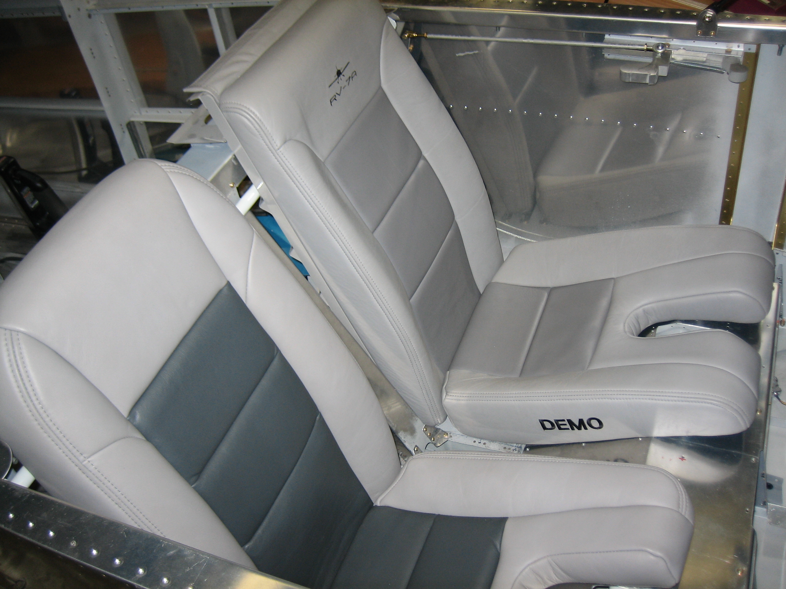
I’m having my interior done by Classic Aero Designs.  I really want to go with the Aviator seats, but I had some concerns about the amount of headroom I’d have.  I spoke with Luke at Classic Aero and he offered to send me out both an Aviator and a Sportsman seat so I could try them out.

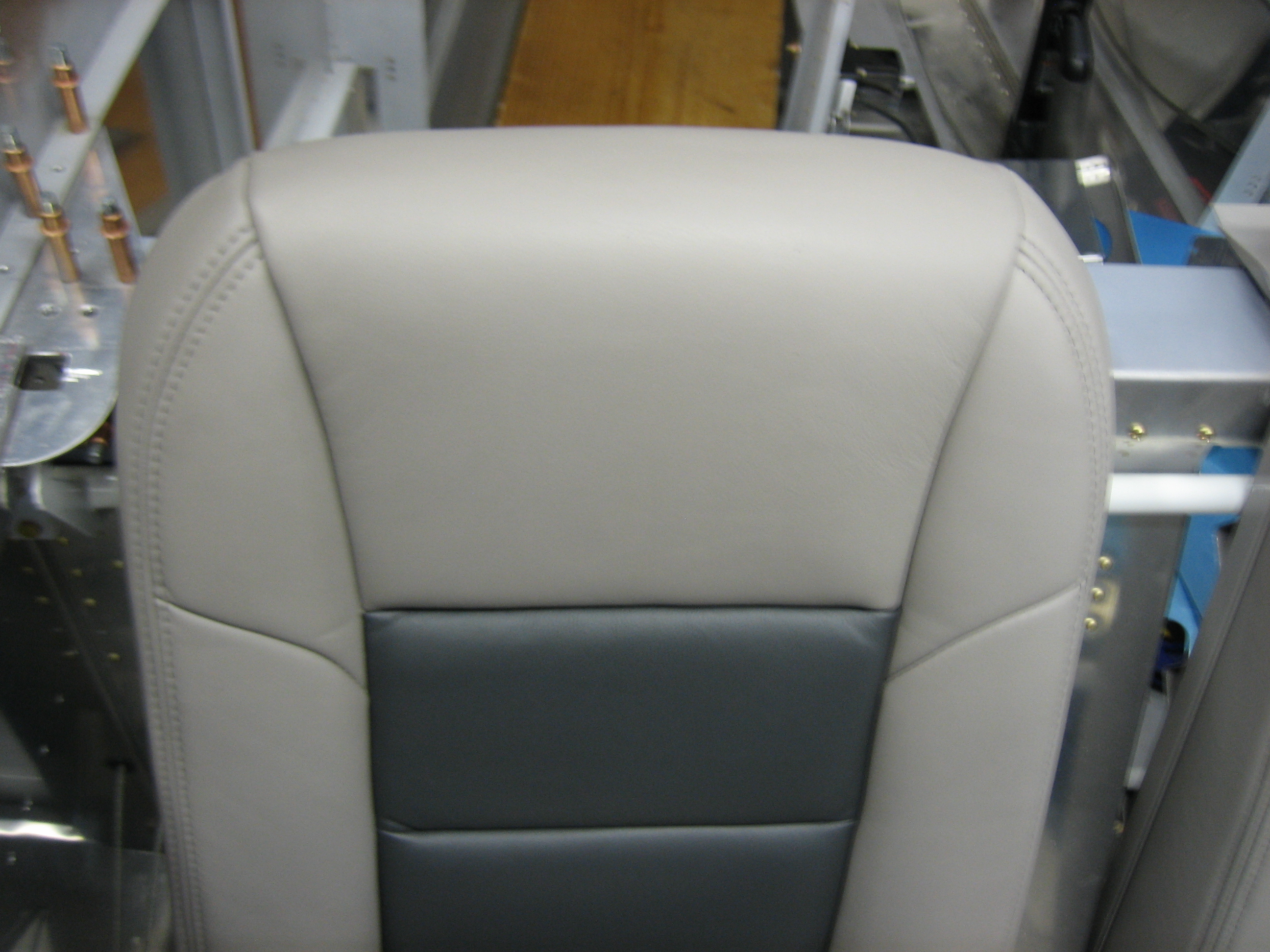
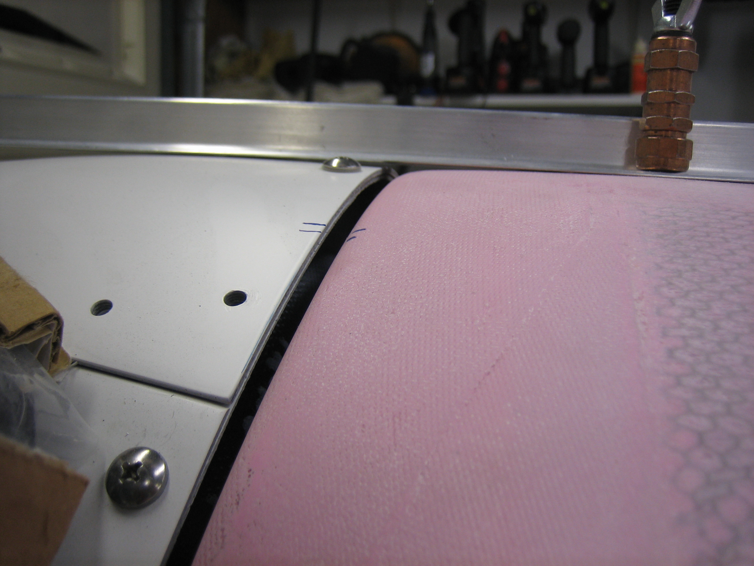
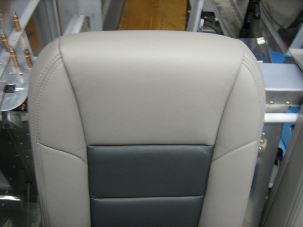
The Aviator seat has a rounded top and an integral frame.  It’s also offered with a headrest and looks much more like an automotive seat.

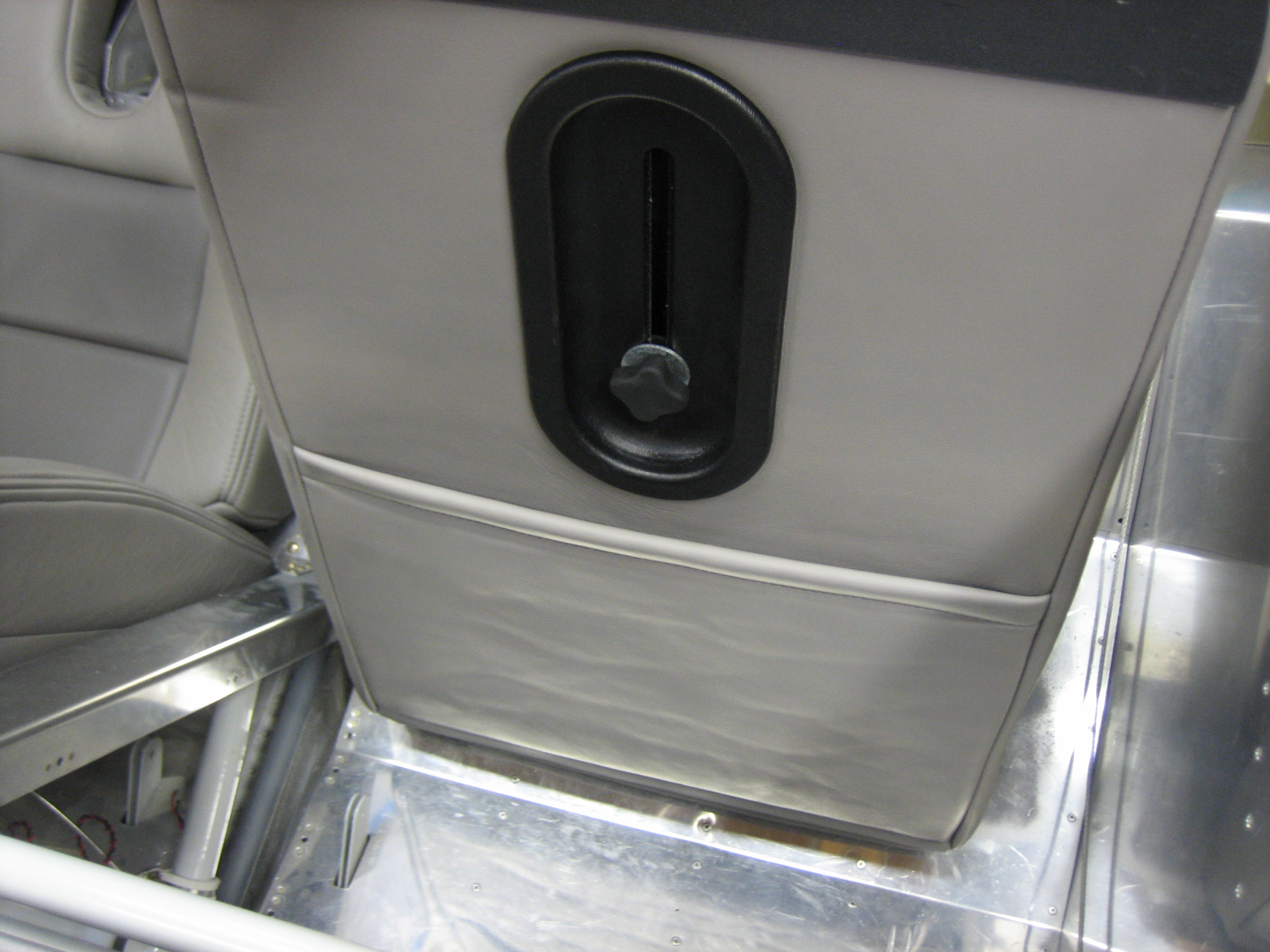
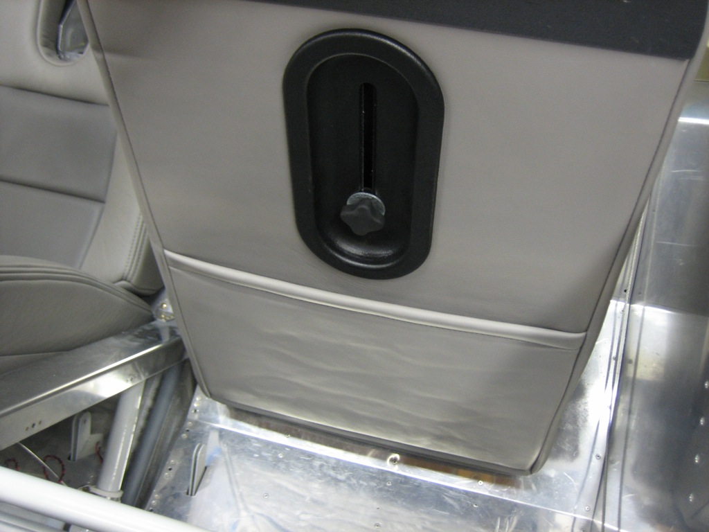
Since it has an integral frame, the back is covered and has a pocket.  There is also an adjustable lumbar support.

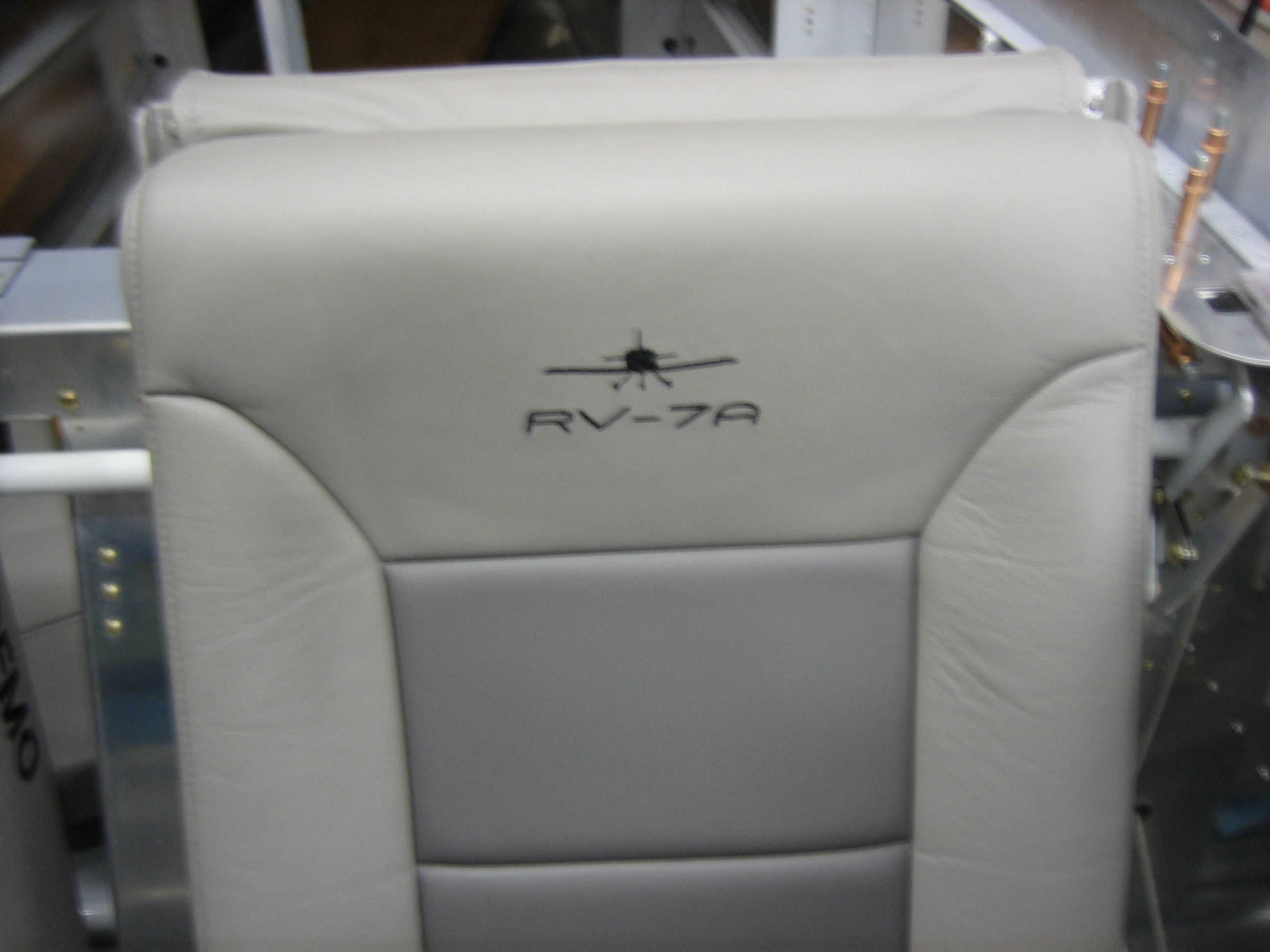
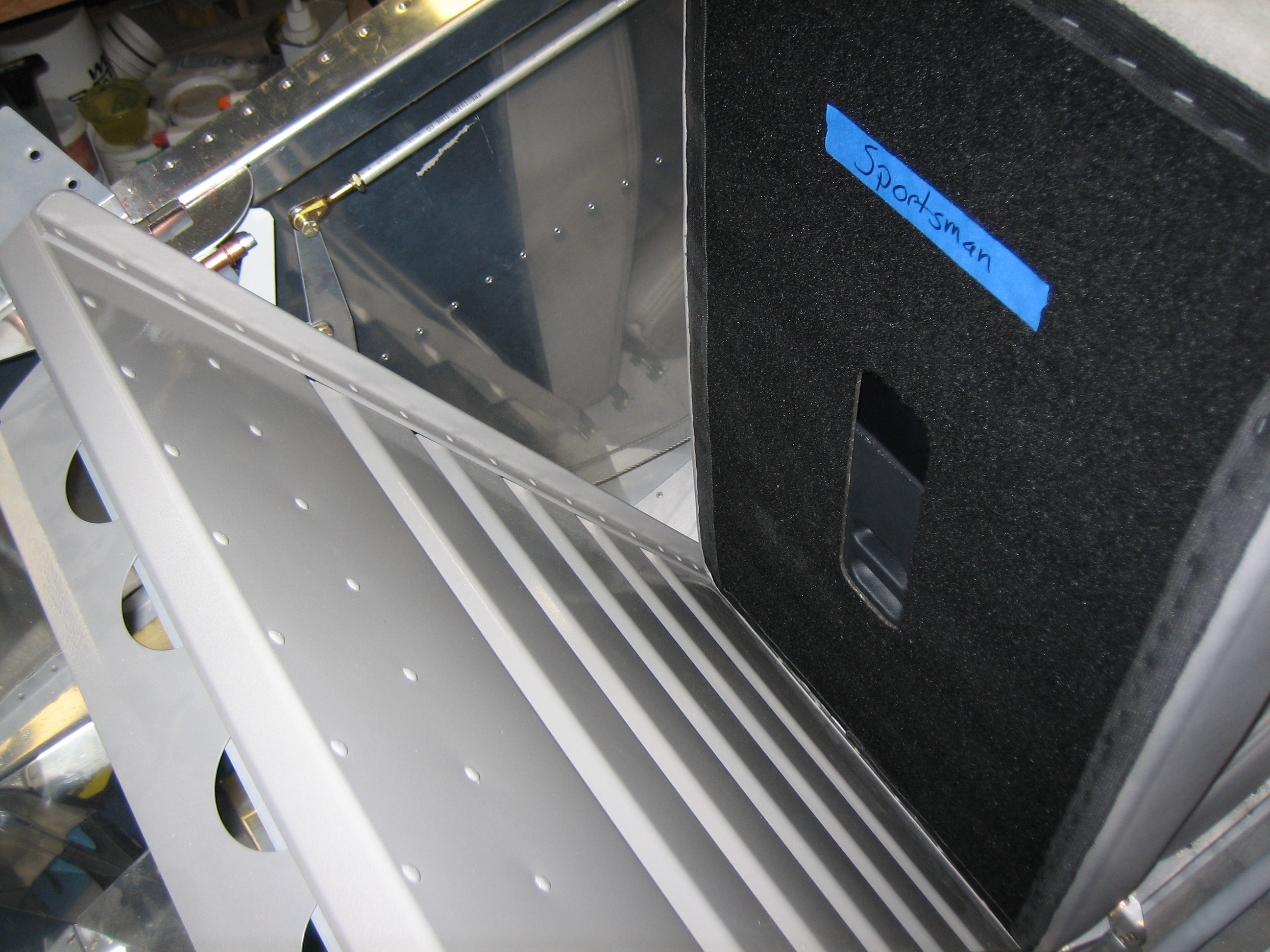
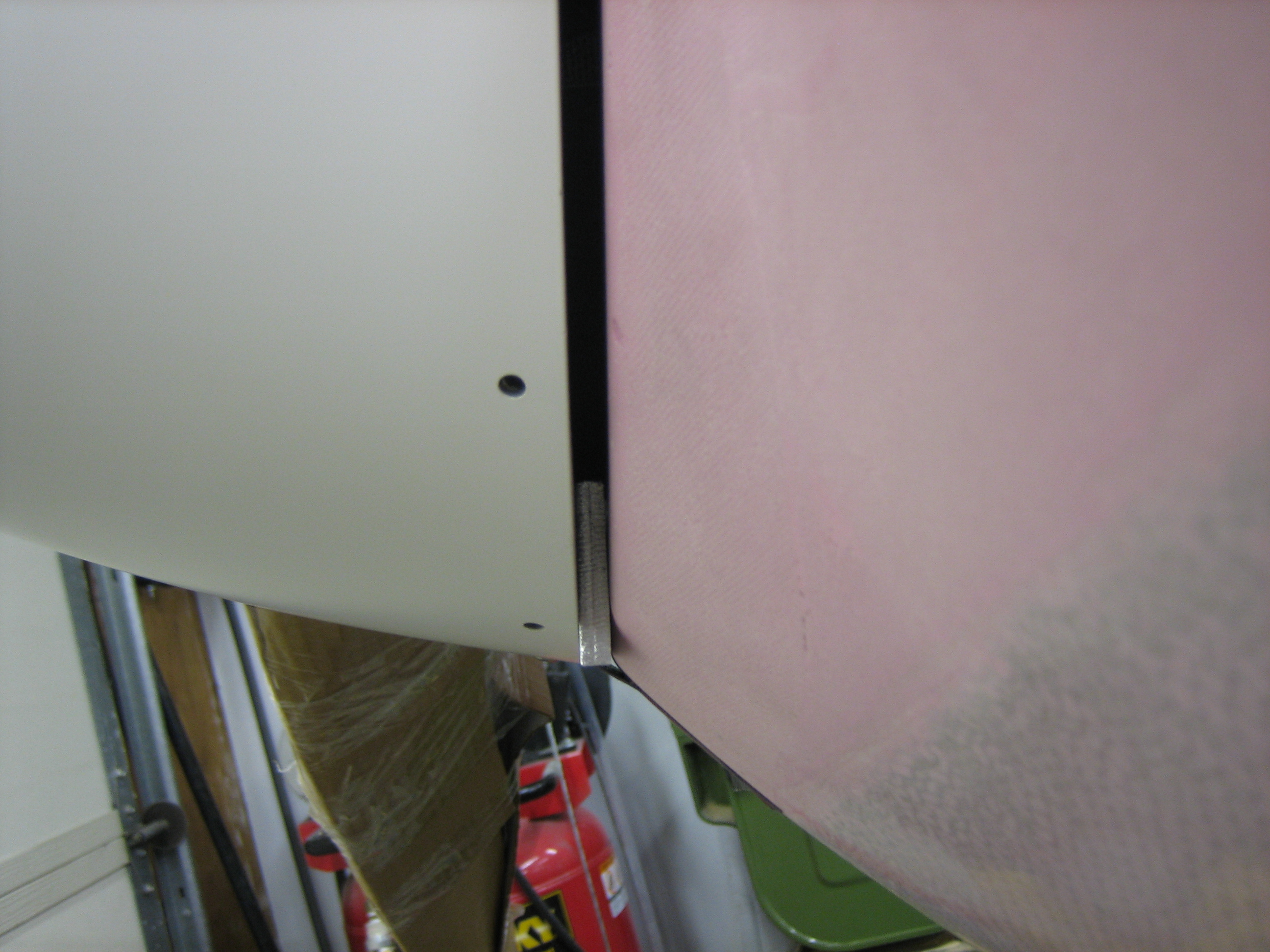
The Sportsman seat has a square top (because it uses the Van’s seat back which has a square top).

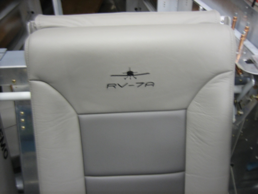
It also has an adjustable lumbar support, but the back must be un-velcroed from the frame to adjust it.

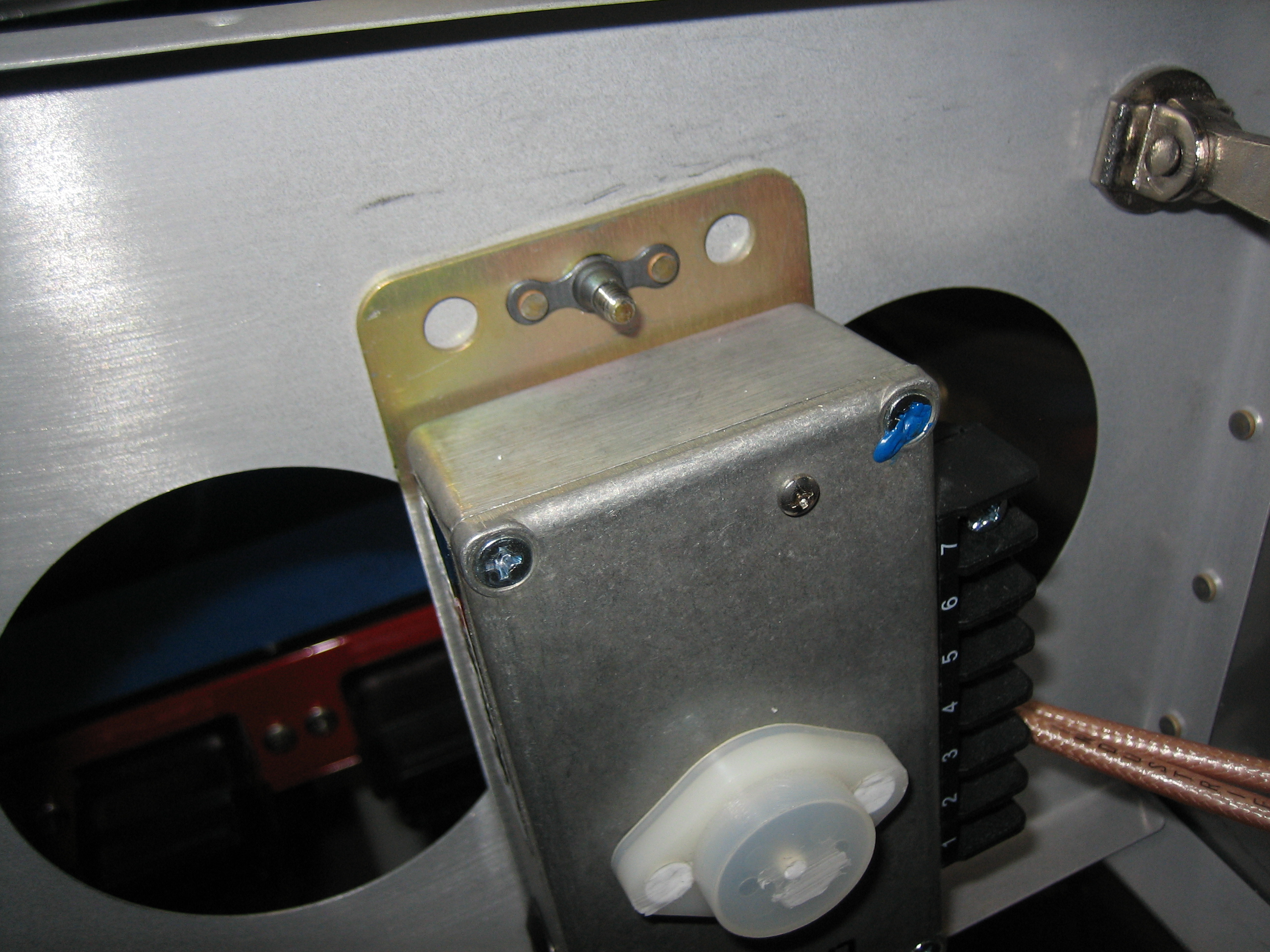
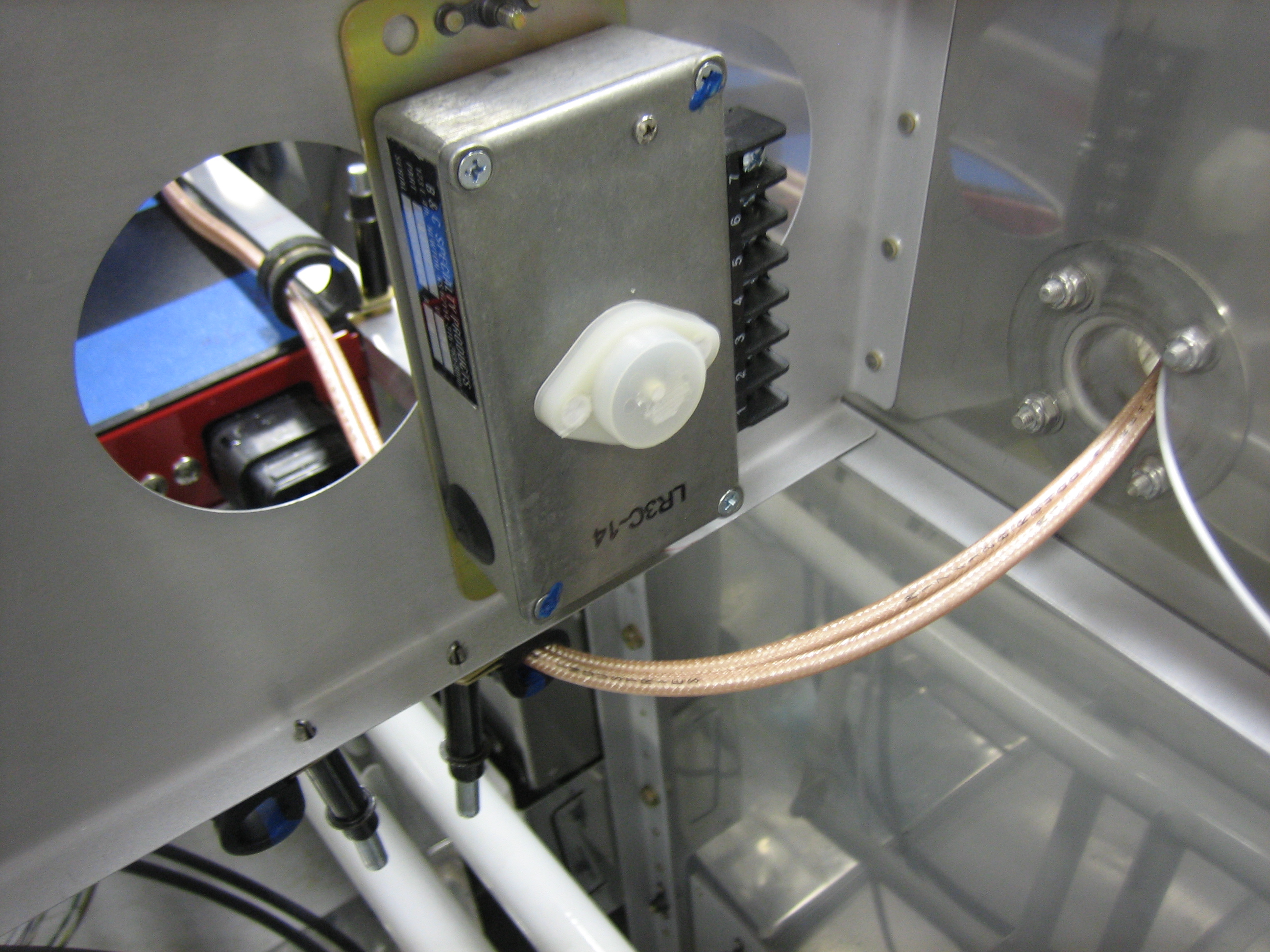
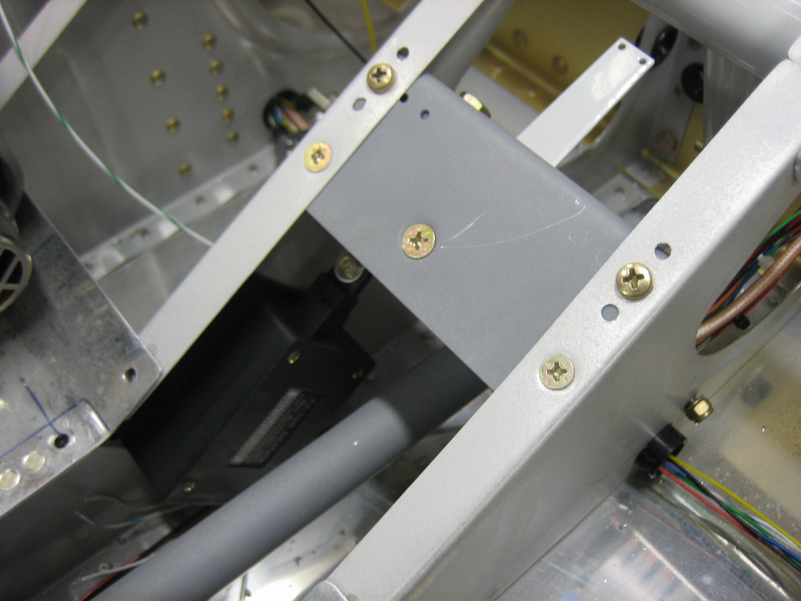
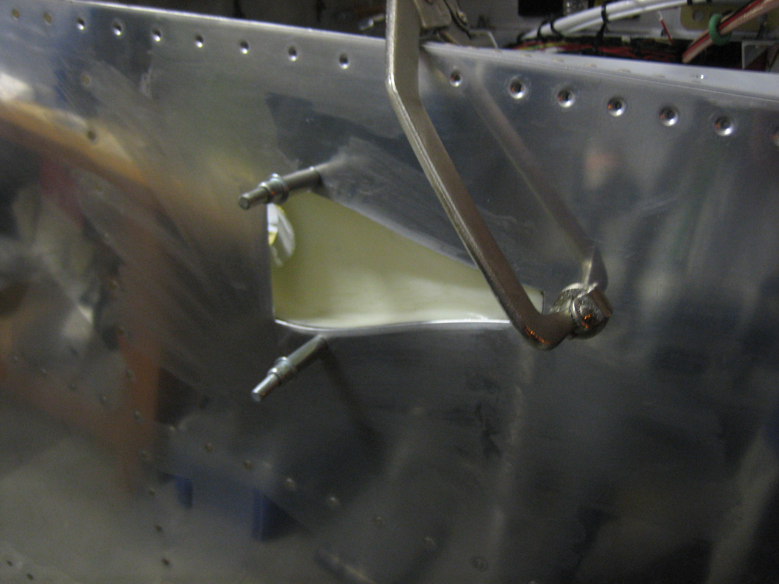
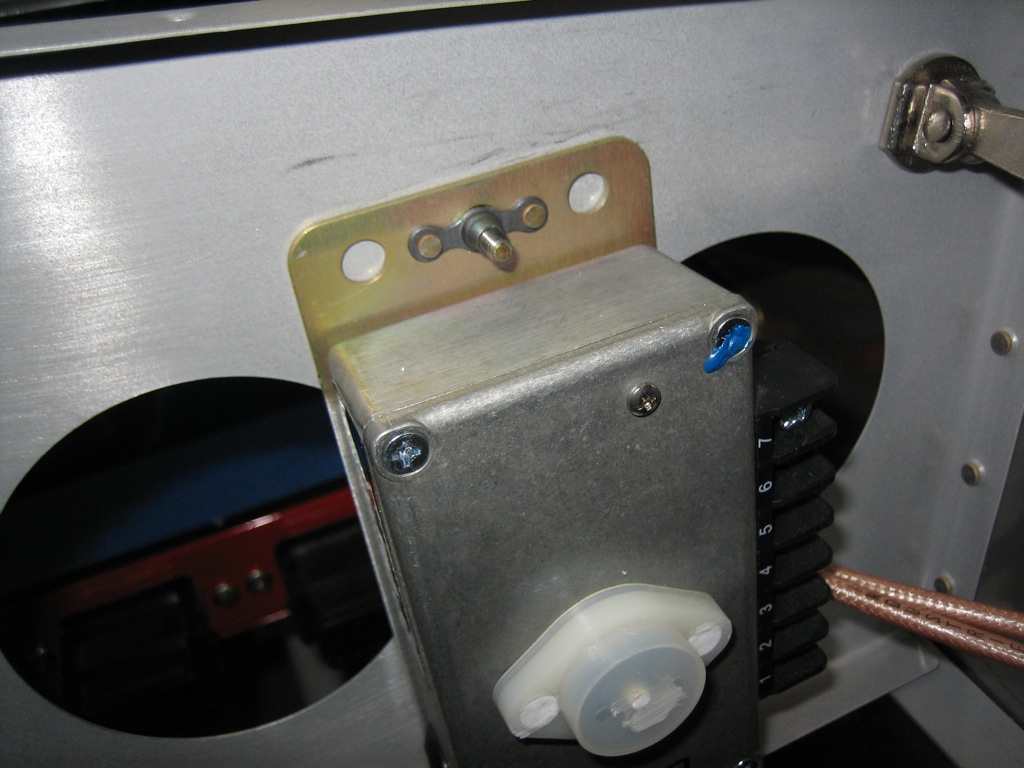
I installed a couple of nutplates on the B&C voltage regulator and installed it to the right subpanel rib.

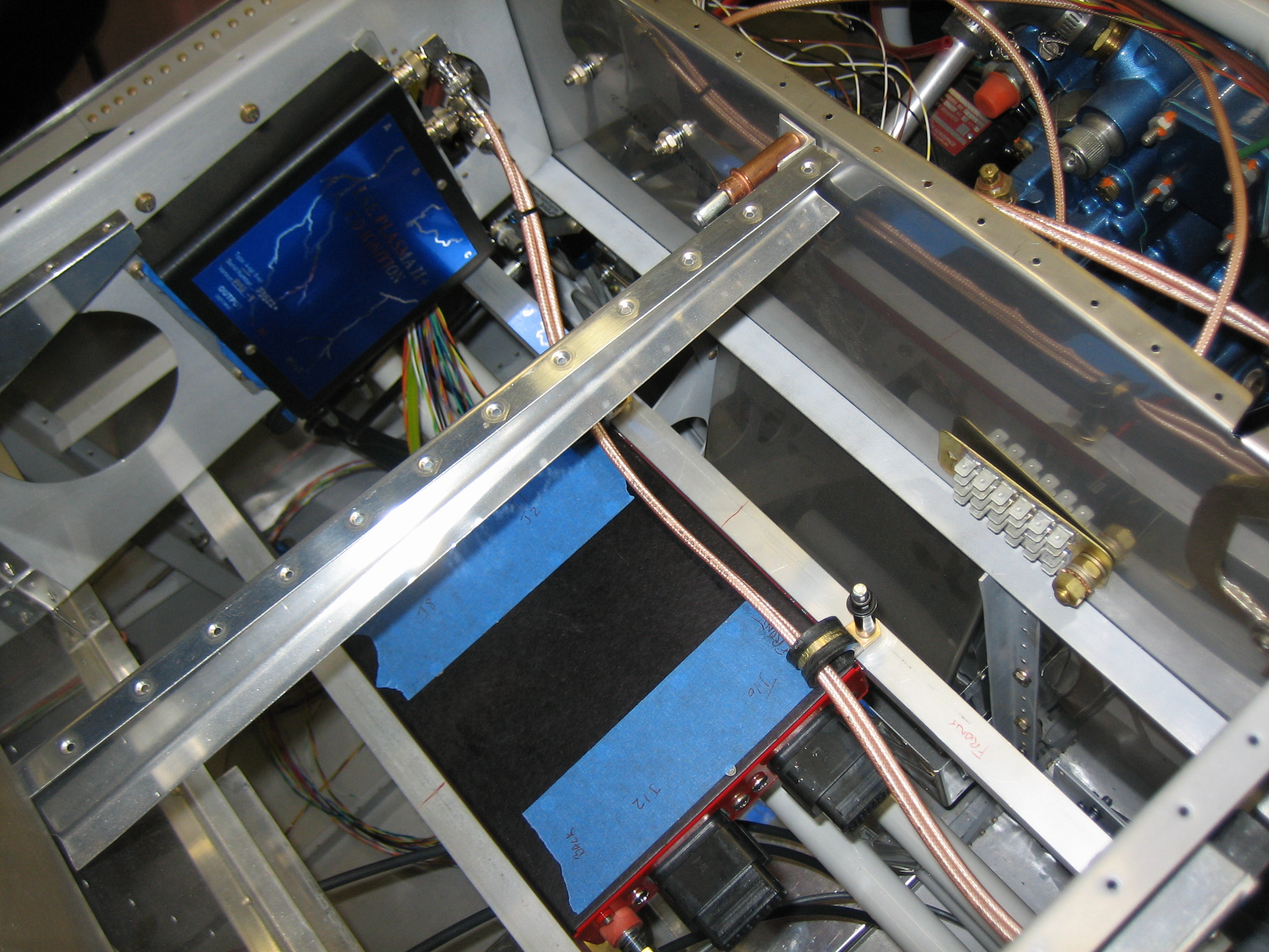
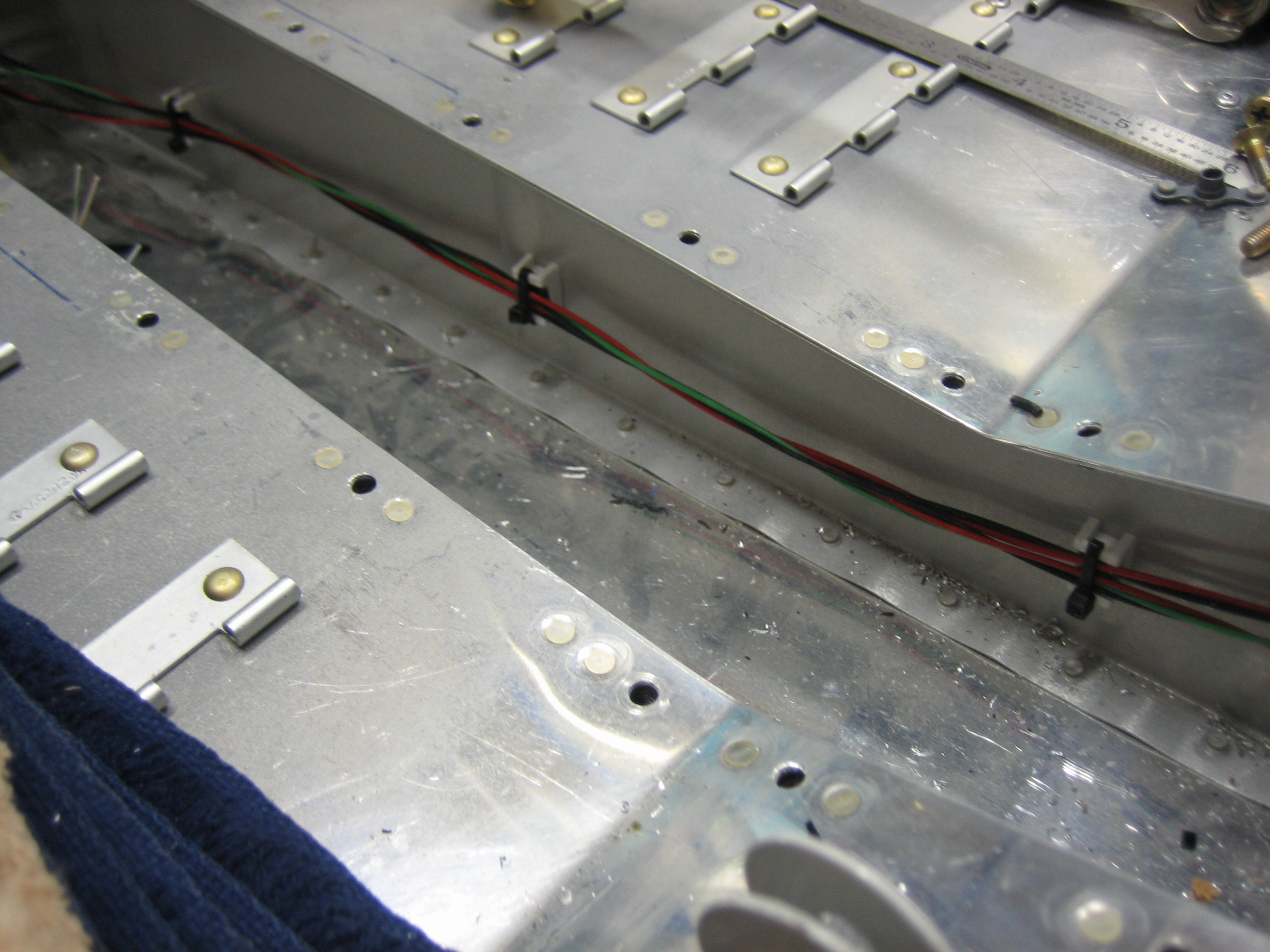
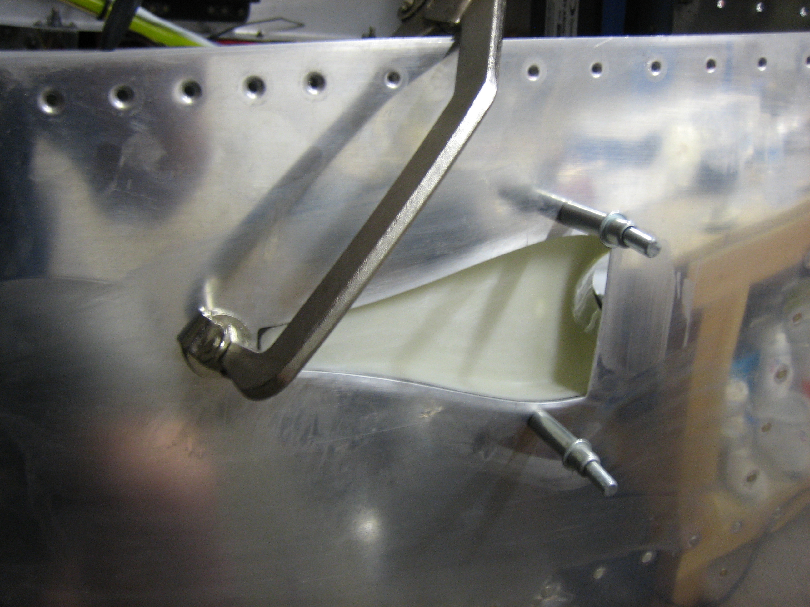
There are two bundles of wires on each side of the VP-X that need support.  I also need a way to route wires between the left and right side of the aircraft.  I installed some adel clamps on the bottom of each subpanel rib.  They’re just clecoed on since I’m sure I’ll have to swap them out for different sizes after I know how many wires will run through each clamp.

It’s not clear from this picture, but they’re aligned with each set of connectors on the VP-X.

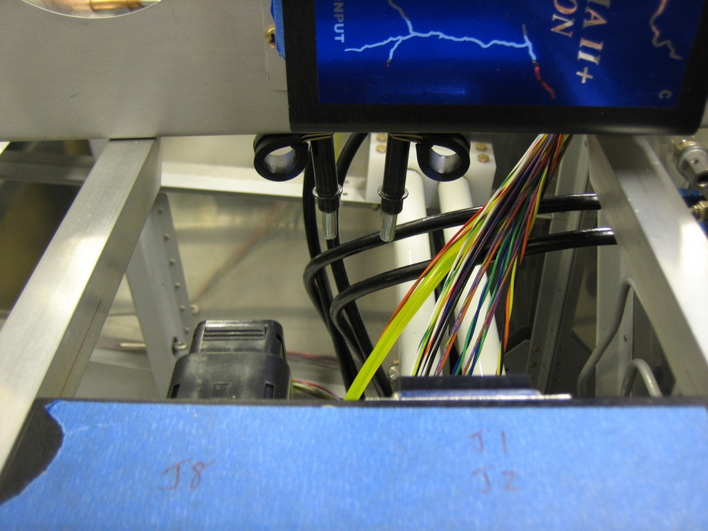
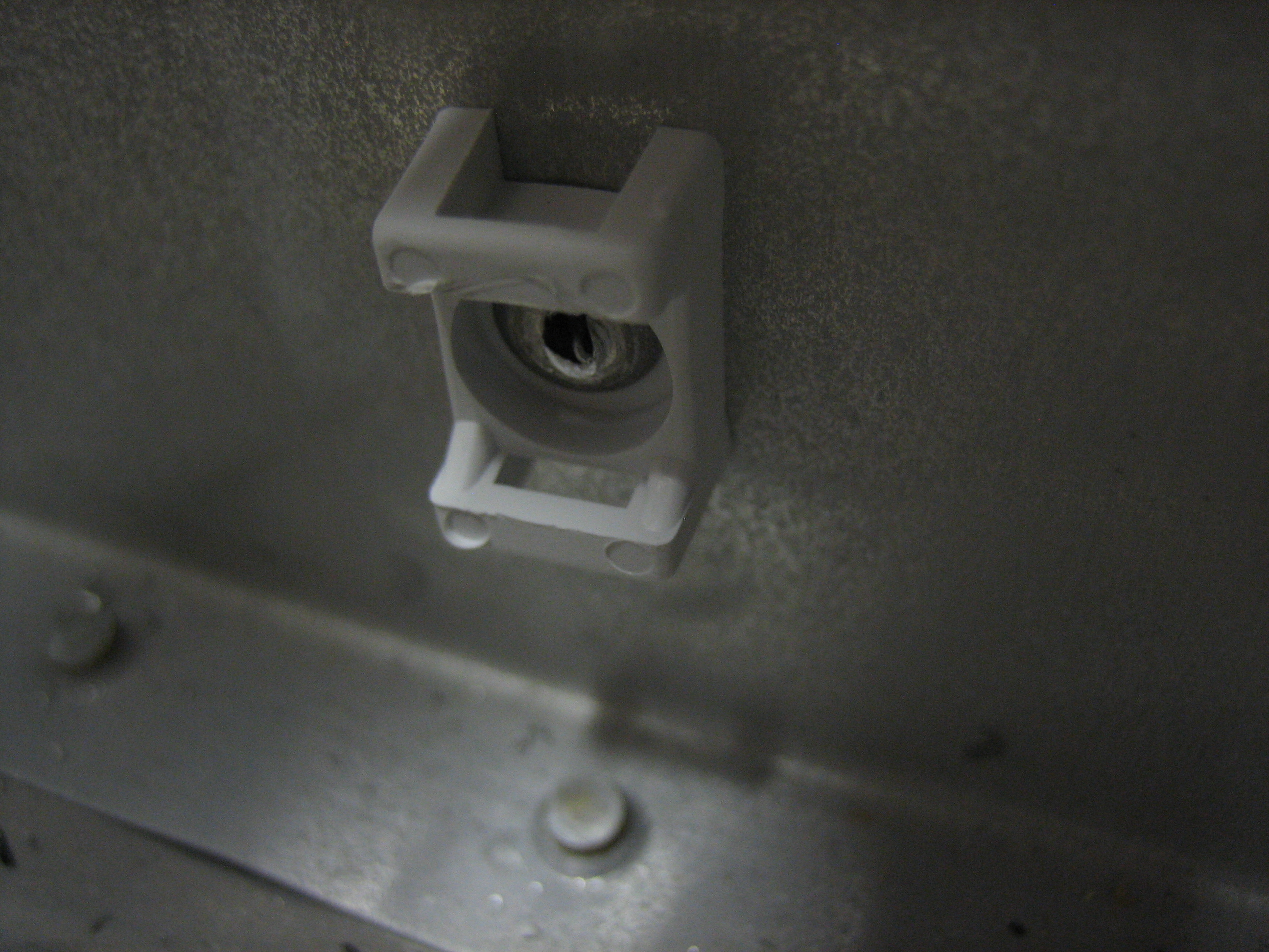
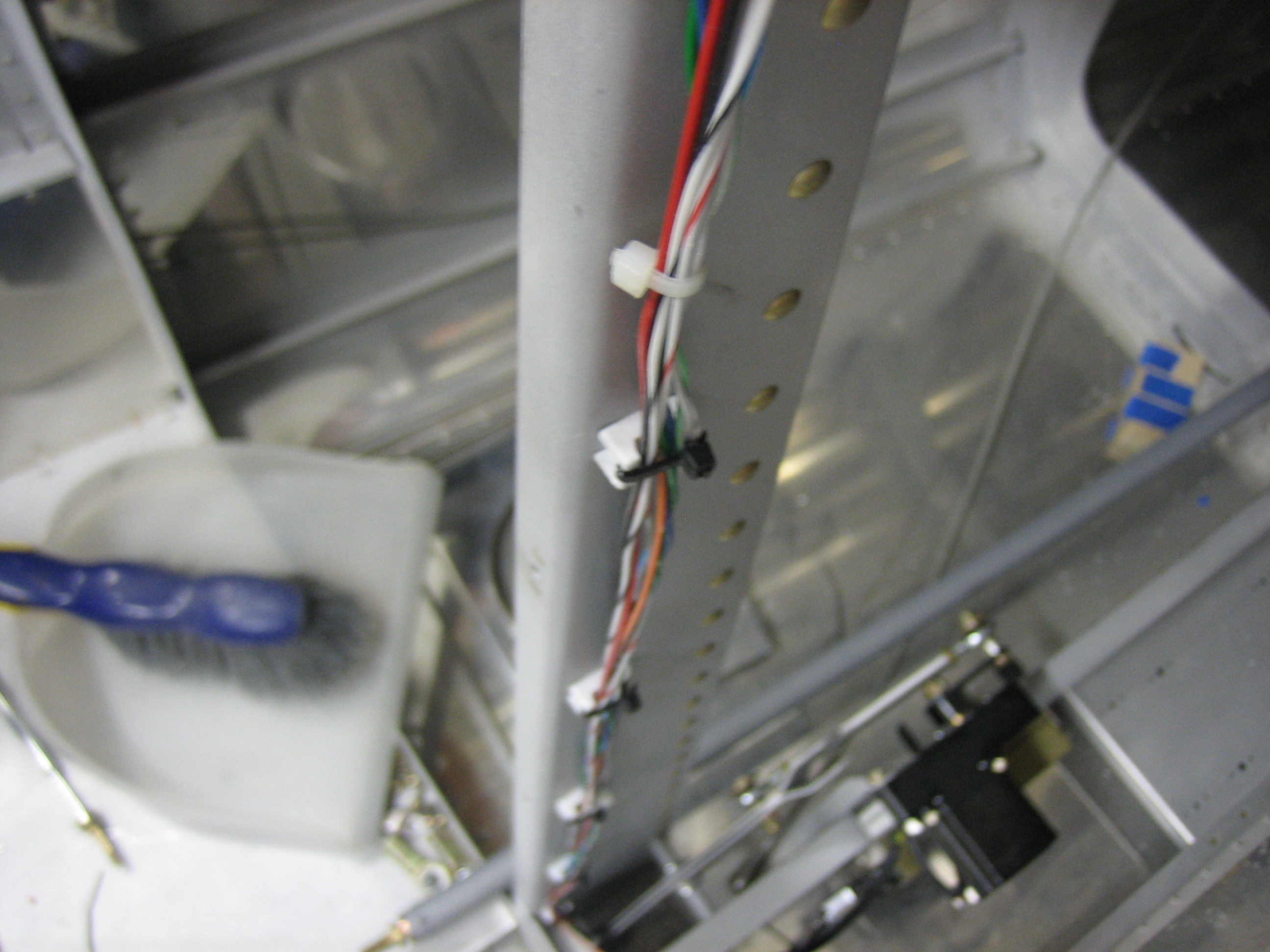
I also installed a couple of adel clamps on the forward VP-X support angle.  Wires that need to cross from one side of the plane to the other will step up and cross on to of the VP-X through these adel clamps.

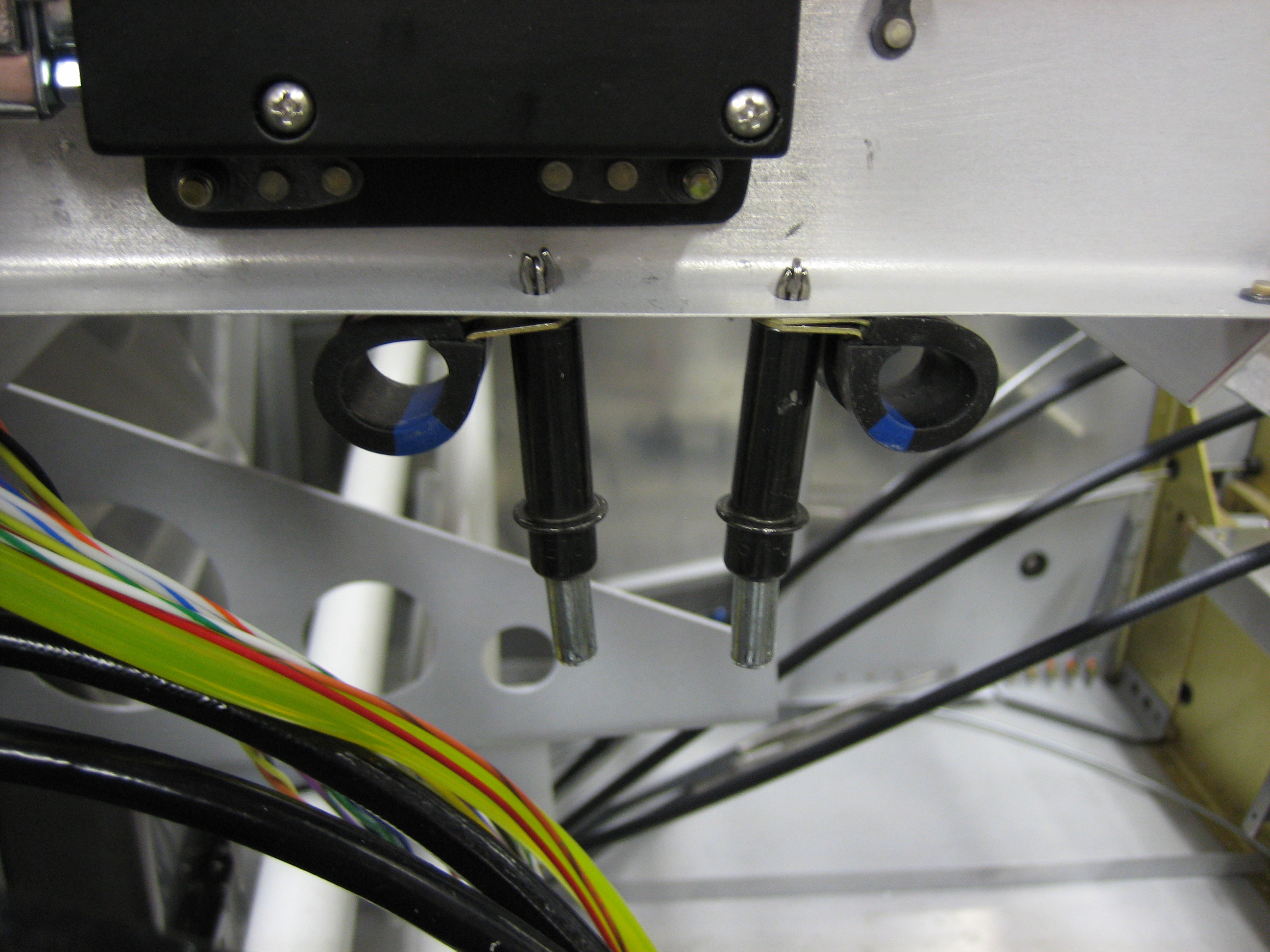
Here you can see that the ignition wires cross over the VP-X, down through the forward adel clamp below the subpanel rib and then out through the firewall pass-through.  Once these are zip-tied to all the other wires running along side them, these will very well supported.

Started Aileron Trim

I replaced the wire from the starter contactor to the VP-X so that I can add protection for the wire close to the contactor.

I also got an order from Aircraft Spruce with a replacement cabin/baggage light.  The one I had had both red and white lights, but as I mentioned earlier, I’m using all white and green interior lights, so I ordered this unit.  I wish this was offered in a natural aluminum anodized finish since this will be the only black anodized aluminum in the cockpit, but it’s not that big of a deal.

Afterward, I decided to get started on the aileron trim.  First up is to fit the bushing block into the bracket.

I radiused the corner so that it nestles tight into the bracket.

Next, I used the sanding drum on my Dremel to notch the bushing so that a cotter pin can be inserted through the shaft.

I drilled various holes in the bracket on the right so that it can be installed between the seat ribs.  I also cut down the shaft of the bracket so that it sits below the surface of the bushing.  This is because the open end of the shaft shown here sits up against the bottom of the bracket on the right.

Mounted Aileron Trim

I drilled the bracket shaft with a #53 bit and installed the cotter pin.  This is a snug fit, so there is zero slop in the bracket.

Here’s the whole mechanism assembled.  The servo pushes on the bracket and will turn it around the shaft.  Spring linkages will connect the other bracket arm to the control sticks to bias the neutral point.

Here’s a closeup of the linkage between the servo and the bracket.

The bushing block is bolted to the mounting flange with one #10 screw and one AN3 bolt through the holes I drilled yesterday.

The hole for the #10 screw was dimpled in the mounting flange and the bushing was countersunk since the seat pan gets installed right above this and there wouldn’t be clearance for a bolt head.  The other hole can just use a normal bolt since there are no space considerations.

Finally, I mounted the bracket between the seat ribs.  I had to remove the elevator pushrod to get the angle drill in here to drill the servo to the skin.

Installed Cable Clamps and Aileron Trim Connector

I got an order from Avery Tools today with some cable clamps that can be attached with screws or pop rivets.  I’m using these in lieu of the adhesive cable clamps in areas where the detachment of the clamp could interfere with the controls.  I’ll likely end up installing these in any spot where it’s fine to drill a hole through the structure.  I really wish I knew about these back when I installed the conduit under the seats and baggage floors instead of the adhesive cable clamps.

I installed several of these along the forward center tunnel to keep the flap motor and flap position sensor wires away from the elevator pushrod.  Jeez, do I need to vacuum in here or what?

I also installed a set of these up the center baggage wall support to secure the network cable to the ADAHRS.

Finally, I slipped some sleeving over the wires to the aileron trim servo and installed a five position molex connector I picked up at Fry’s this morning.

Started Fabricating Vent Brackets and Worked on Cowl

I started fabricating one of the brackets that will be used to mount the air vents.  These are fabricated out of 0.063″ stock which is the same as the instrument panel.

Here’s how it fits in the plane.  You can see how it nestles nicely up against the instrument panel and the flange of the vent overlaps both.  I’ll cut off the lower right of the bracket at the small horizontal black line and let the bracket follow the curve of the vent around to the bottom.  I left the bracket a little tall on the left side for now since I had Classic Aero Designs fabricate the side panels to the original height of the vent brackets.  I don’t know if they’ve cut these parts yet, so I’ll see if they can still change them.  If so, I’ll cut this off straight.

I reinstalled the cowl so that I can continue the fitting.  I had previously put this on hold while Van’s evaluated whether the flanges on the cowl sides were cut too short but haven’t gotten back to it until now.

I had previously cut the aft edge of the bottom cowl to length, so I carefully lined up the cowl all around and drilled a couple of holes on each side to the stainless steel hinge to lock the bottom in position.

I put a work light inside the cowl and marked the approximate cut line on the sides.  It’s too late to run the cutoff wheel tonight, so this is a good place to stop.

Trimmed Aft End of Cowl

I trimmed the sides of the lower cowl and then sanded them so that they tuck in against the hinge (which I also drilled but didn’t get a picture of).  I drilled one hole through the top of each side into the hinge to lock the position of the lower cowl in place.

I then marked and trimmed the aft end of the top cowl.  This will need a little sanding, but it is enough to let it drop down against the hinge.

Unfortunately, there is still a gap along the sides.  The plans (and other builder’s websites) say these should overlap along the sides so that you can trim them both to get a perfectly straight joint.

The left side is even worse with a roughly 1/8″ gap down the entire side.

The fit at the front still looks great.  Here’s the lineup at the top.

And the lower point on the cowl lines up nicely with the spinner.  Clearly the front of the cowl is in the right spot and the back is pulled in as tight as it can go.  Time to chat with Van’s again about this.

Installed Sniffle Valve, Oil Drain and Air Intakes

I installed the sniffle valve in the aft port in the intake manifold (the upper brass fitting).  This is a check valve that opens when on the ground to allow excess fuel or water that leaks into the engine manual to drain out of the bottom of the engine and onto the ground.  I also drained the preservative oil out of the engine and installed the quick drain plug into the sump and safety wired it.

I then mixed up some proseal and attached the air vents to the side of the fuselage.  I drilled a couple of holes for alignment purposes.  I’ll fill these in later with some filler.  A lot of builders pop rivet these on, but proseal is tenacious stuff and will hold these quite well.  This is the left side.

…and this is the right.