I’ve always had a slightly erratic fuel flow. The fire sleeve I added a couple of months ago helped, but didn’t fully resolve the problem. Although I still suspected a heat problem, I called Dynon to get other ideas. They sent me a document on diagnosing fuel flow issues and wanted me to remove the 90º elbow on the outlet before trying anything else. I decided to call EI who makes the sensor to see what they thought and they told me that the number one cause of an erratic fuel flow sensor was a bad electrical connection to the sensor.
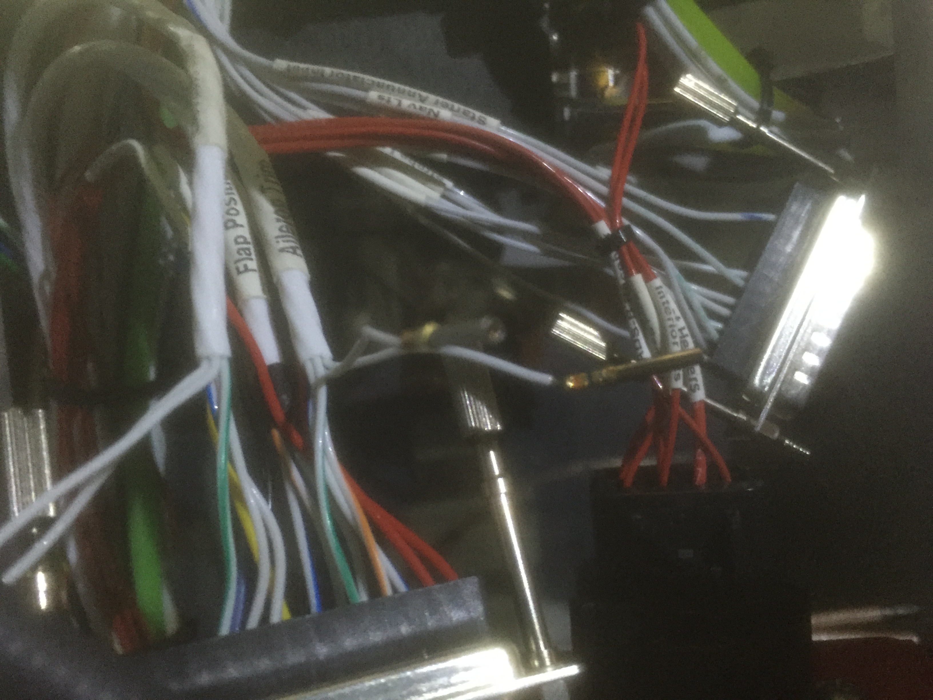
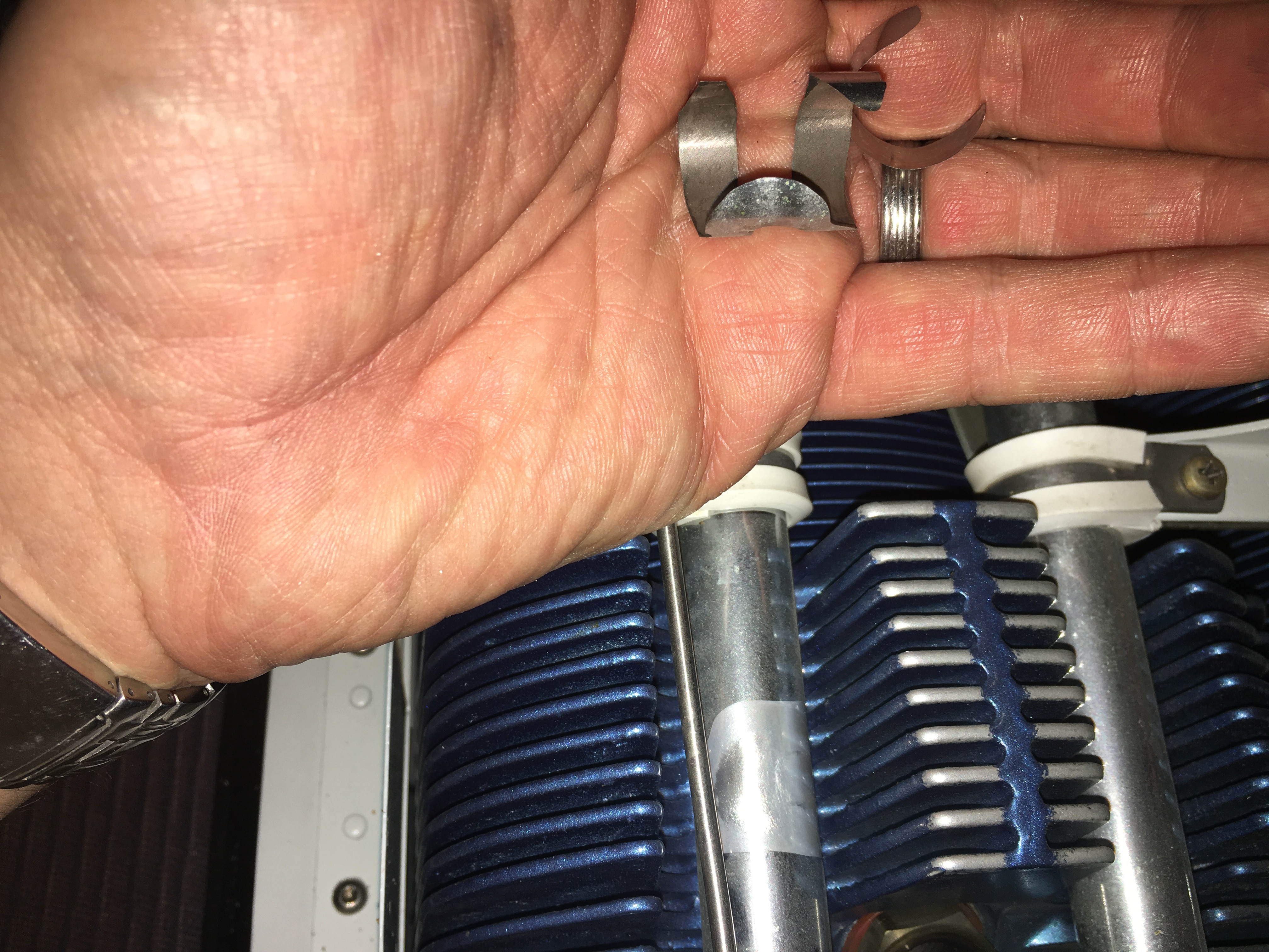
I pulled the heat shrink off of the knife splices for the three wires going to the sensor. I re-crimped them and squeezed the splices so that they’re much tighter. I then re-heat-shrinked them and took it up for a short flight. The fuel flow was rock solid.
Update: with over 5 hours on the plane now since redoing the connections, I’m pretty sure this is now resolved.