I ordered the wing kit today. Van’s says the lead time is 8-10 weeks typically, so I should get it sometime in early May. I only have the rudder and elevators left to do from the empennage, so I’ll likely be done with that before the wing kit gets here. Since I now have all of the materials to do the fiberglass tips on the empennage components, I’ll probably get started on that while waiting for the wing kit to get here.
Received Wing Kit Shipping Date
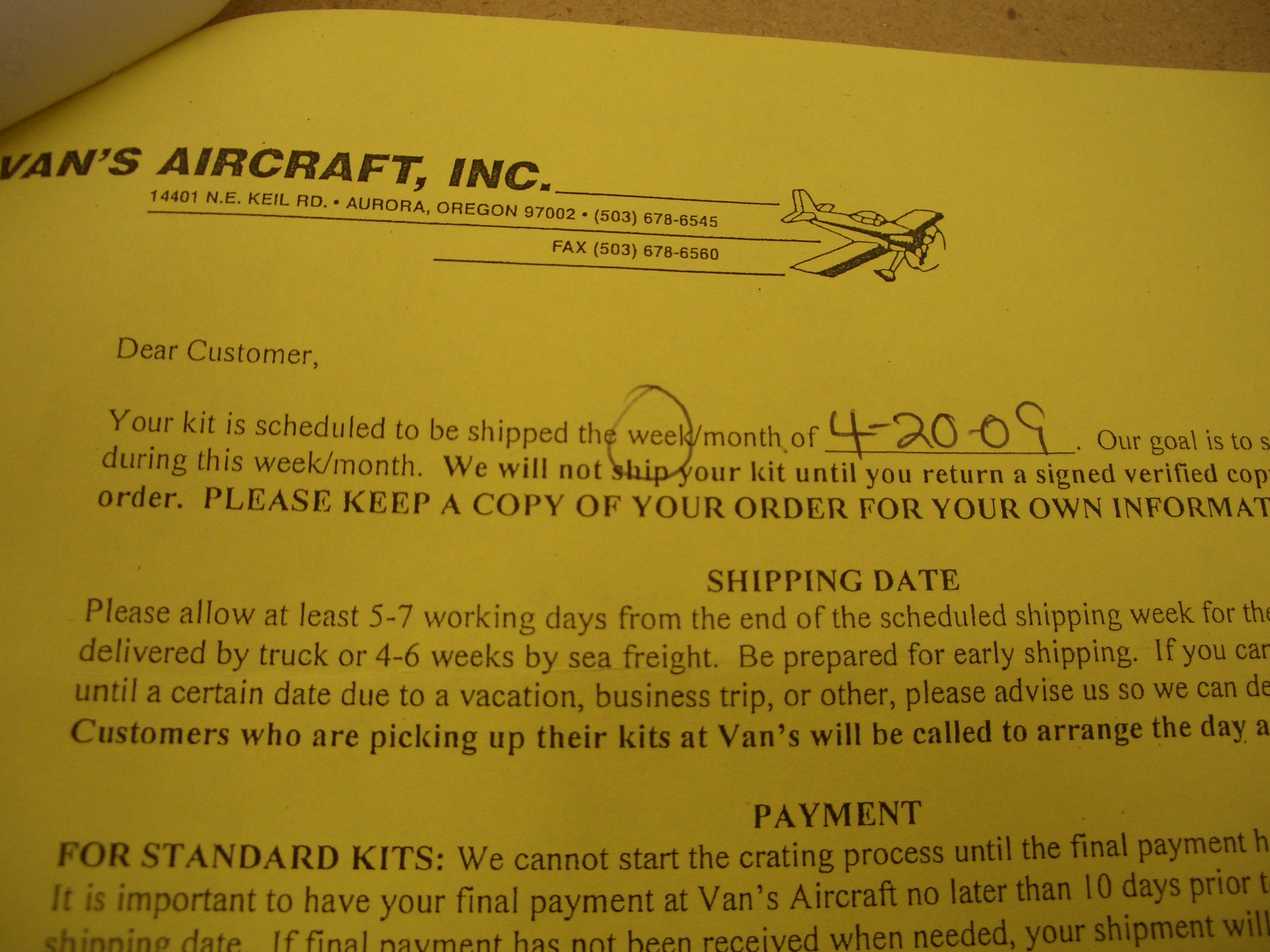
I received confirmation from Van’s today that my wing kit will ship on April 20th, so I should have it within a few days after that. That gives me 4-5 weeks to finish up the empennage which should be no problem.
Wings Arrived!
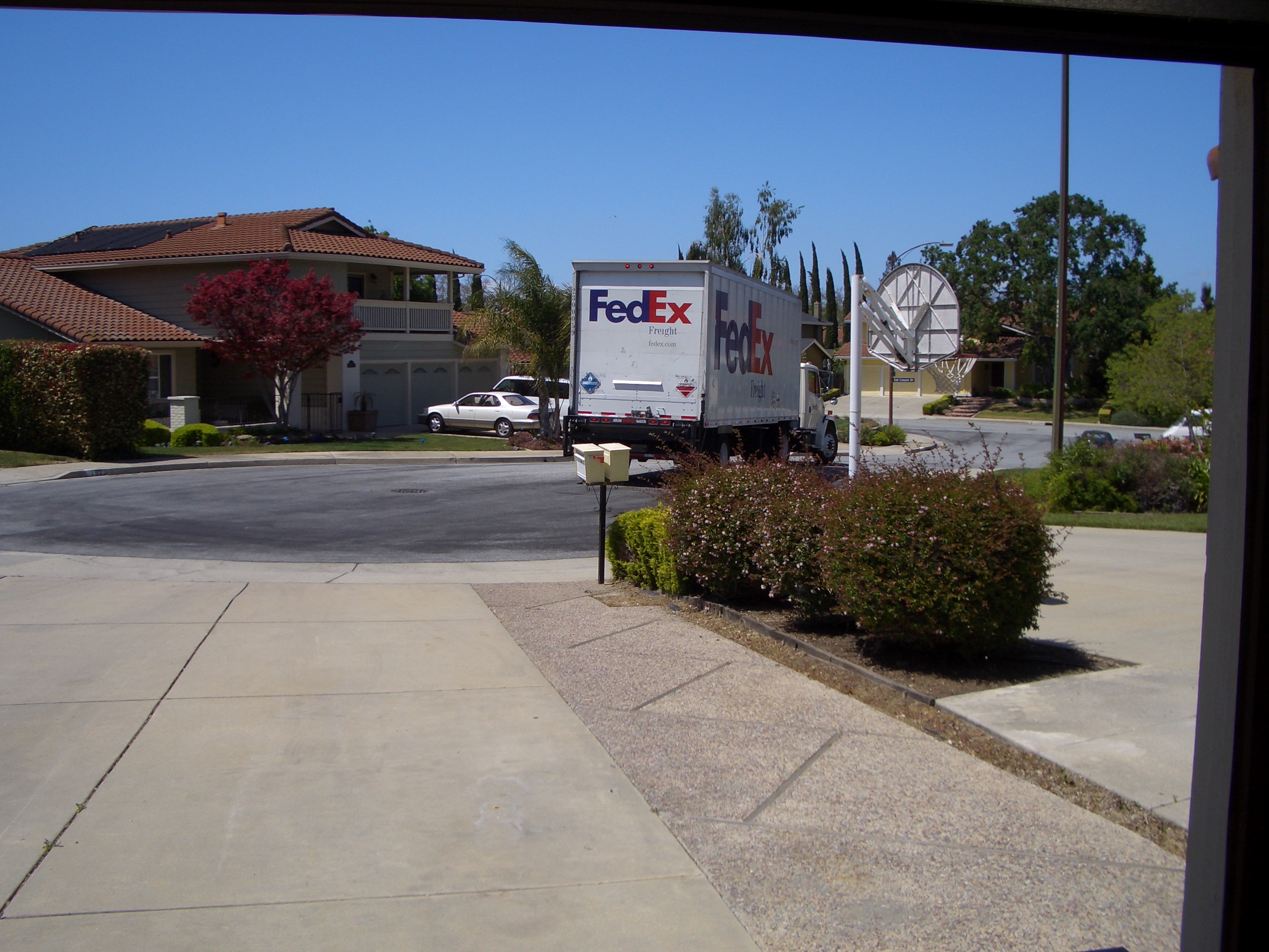
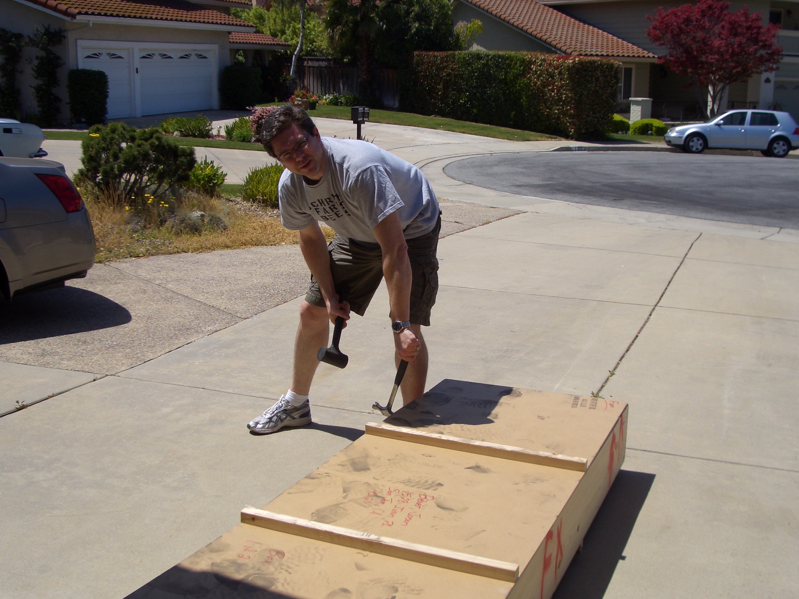
About 1:30 this afternoon, the FedEx freight guy showed up with my wing kit.
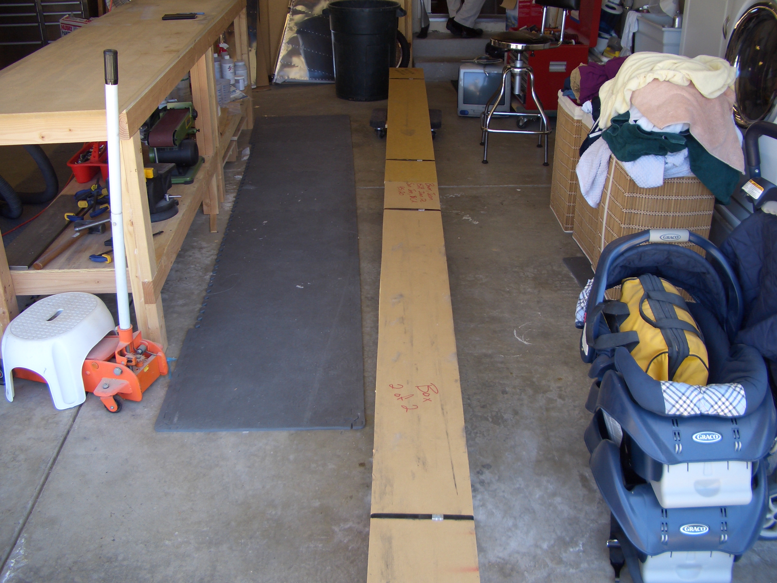
My buddy Dan dropped by to help me unpack the boxes since I didn’t have room in the garage to store them. This is the box containing all of the skins, ribs, tips, etc.
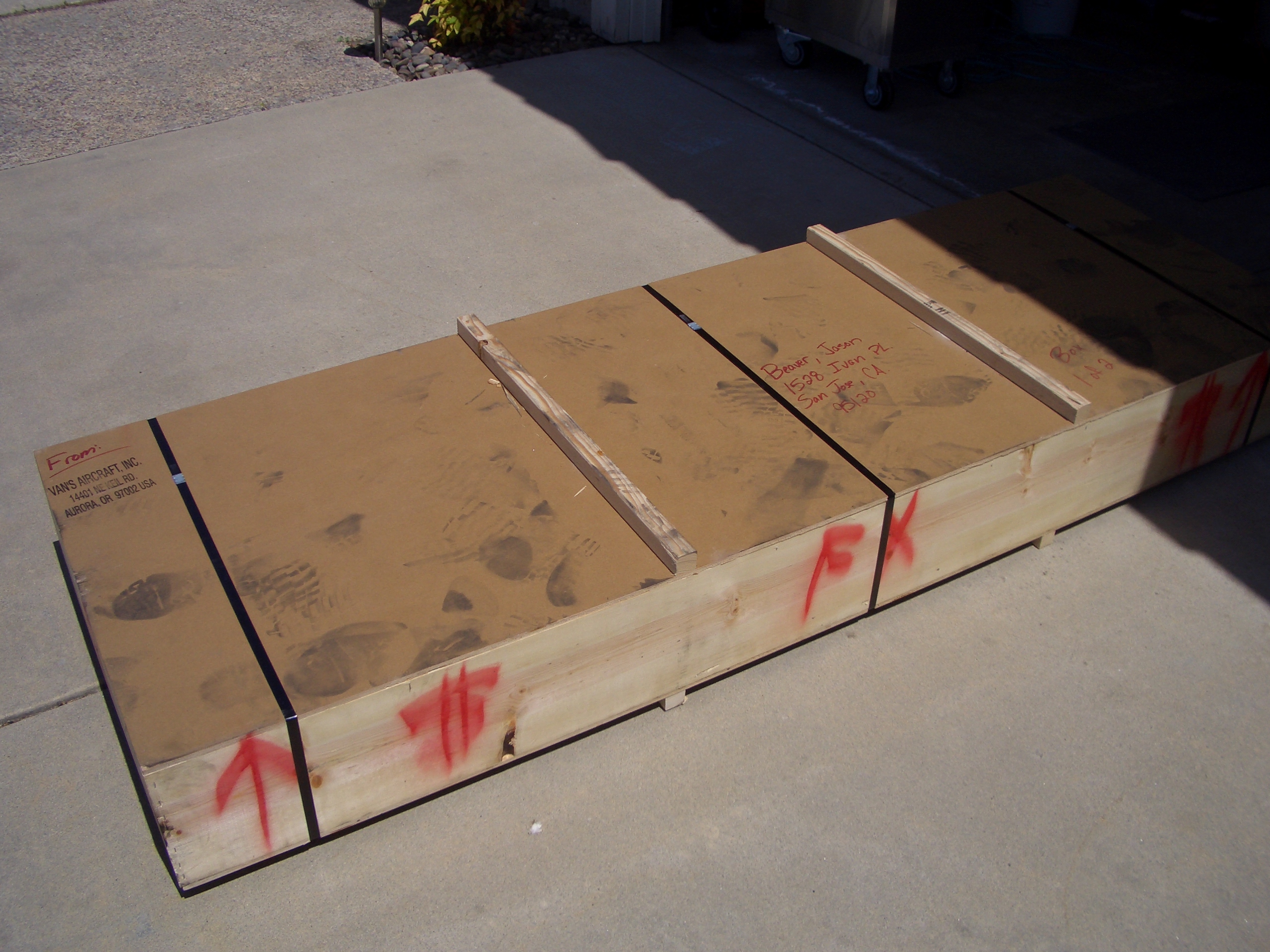
And this long box contains the spars and most of the hardware.
Cracking open the first crate.
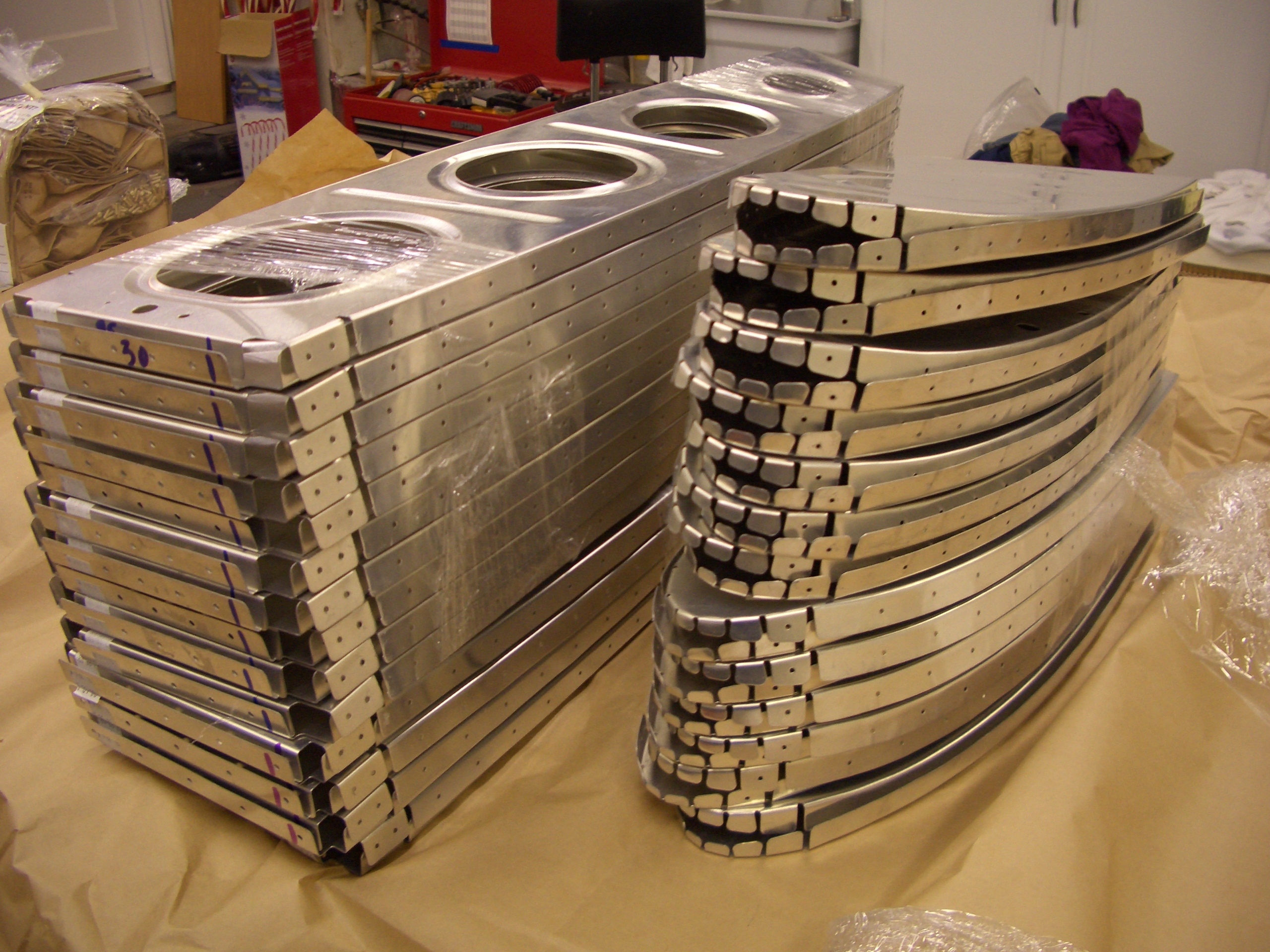
Main wing ribs on the left and leading edge ribs on the right. These things are seriously distorted (this is normal). It will take a lot of fluting and tweaking before these are completely flat.
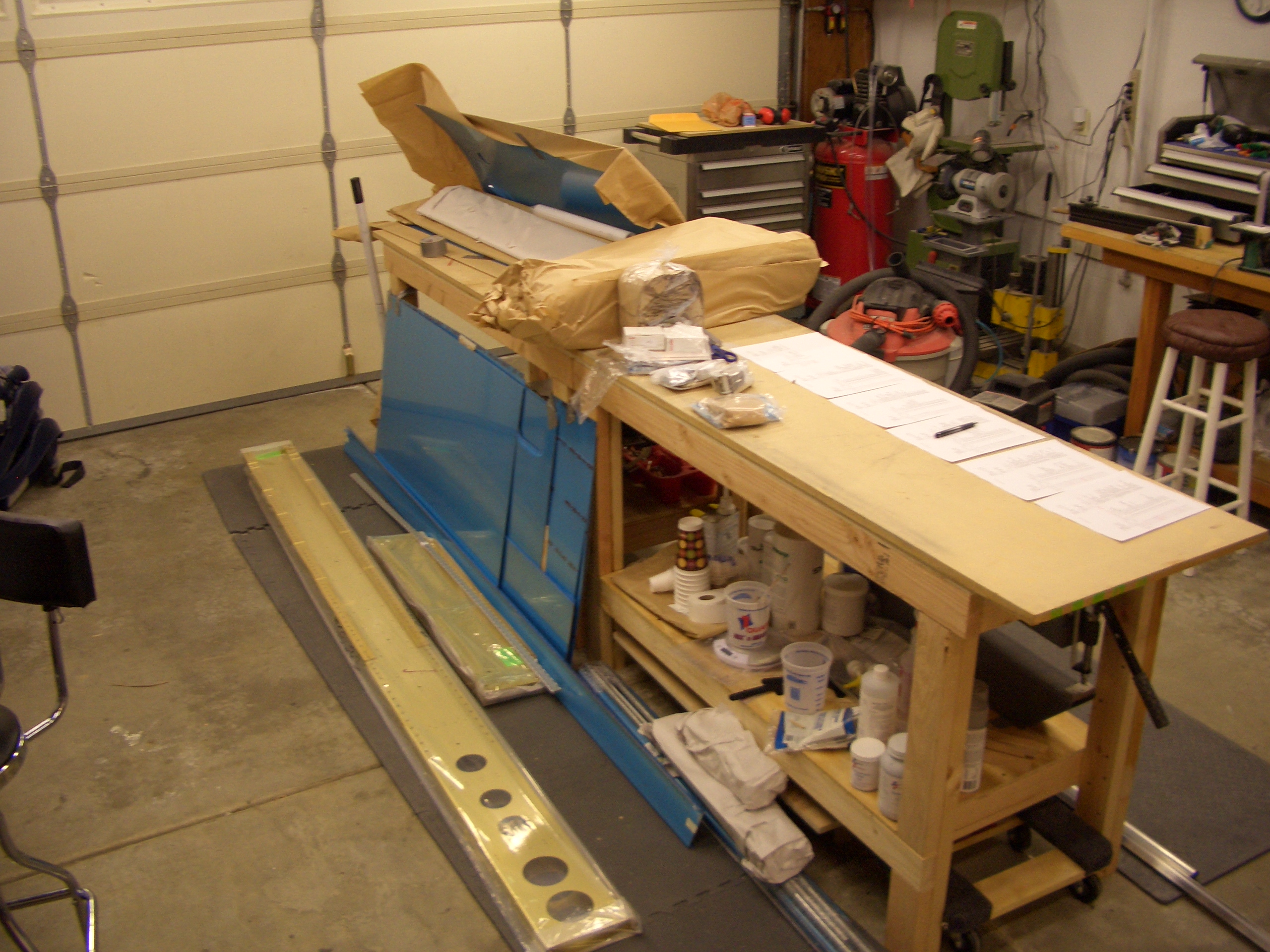
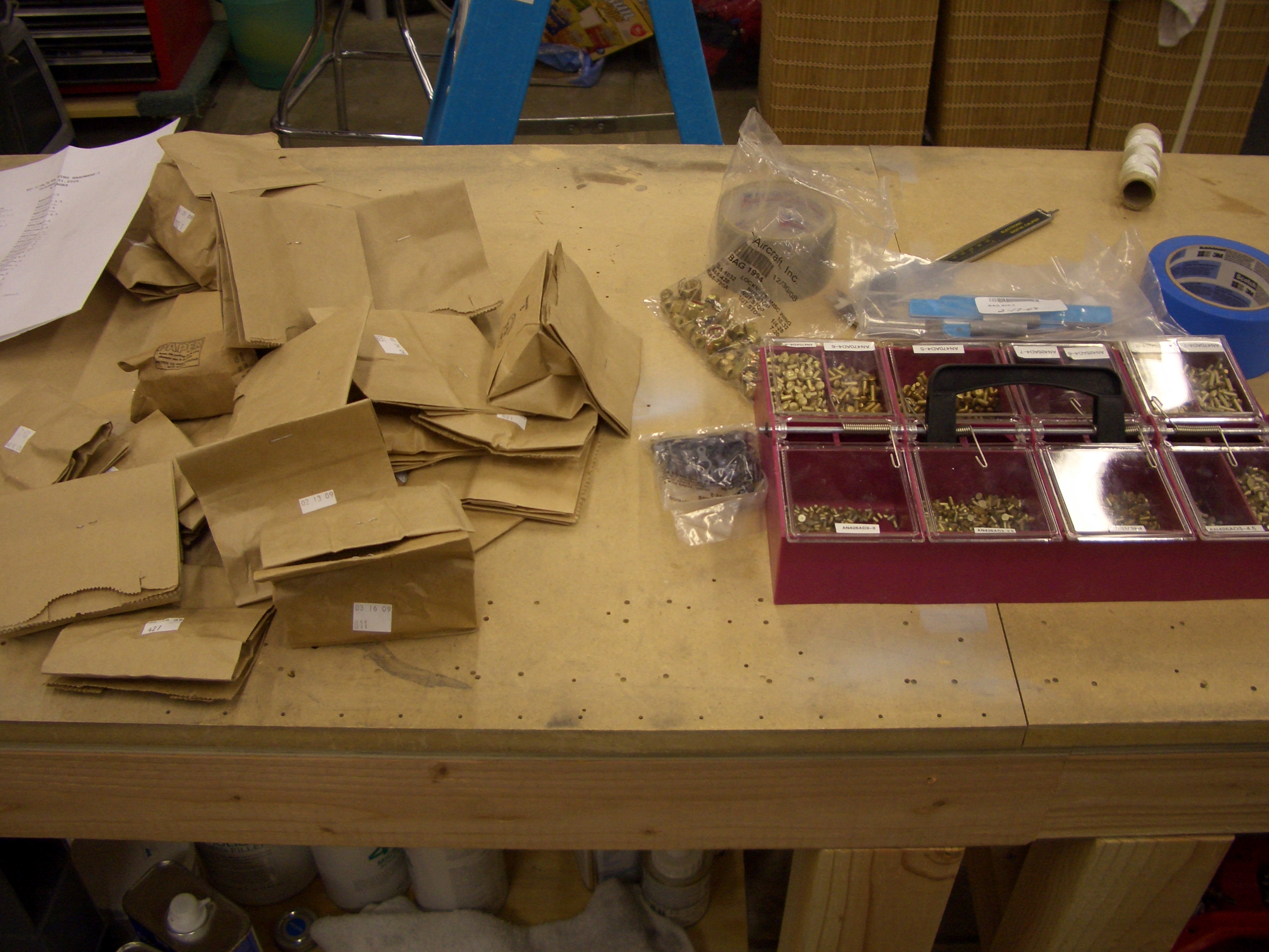
Inventorying the hardware. The are a lot more components in the wing kit. I had to hang up a second set of organizer drawers to hold all of the parts.
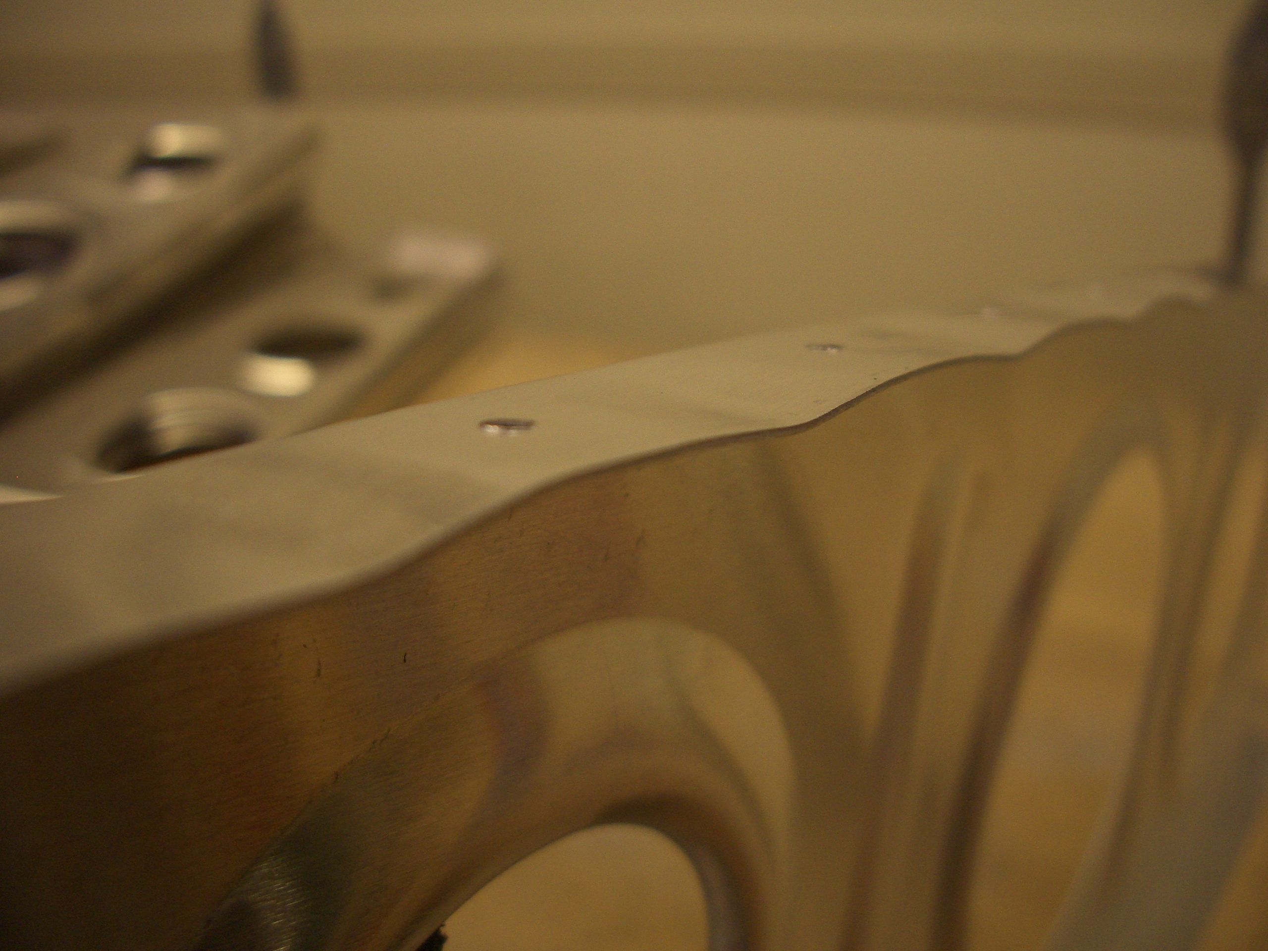
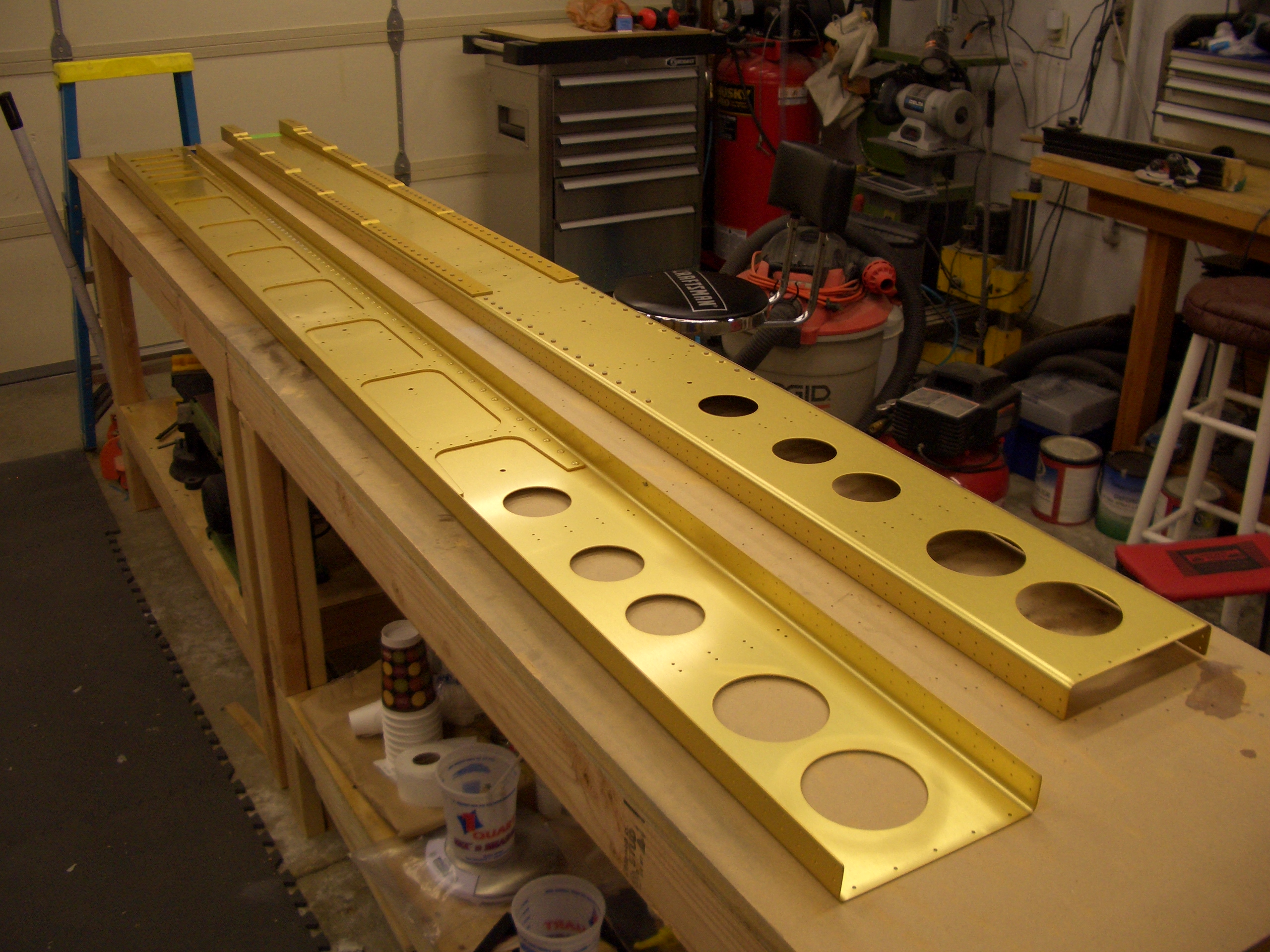
Spars laid out on the benches. This things are truly works of art. It’s a shame that these will never be seen on the completed airplane.
Started Wing Kit
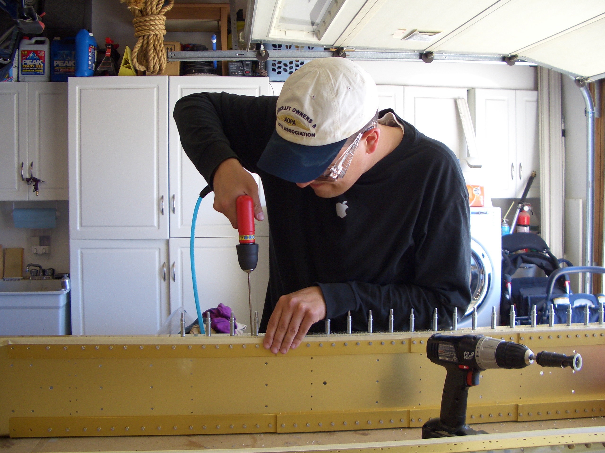
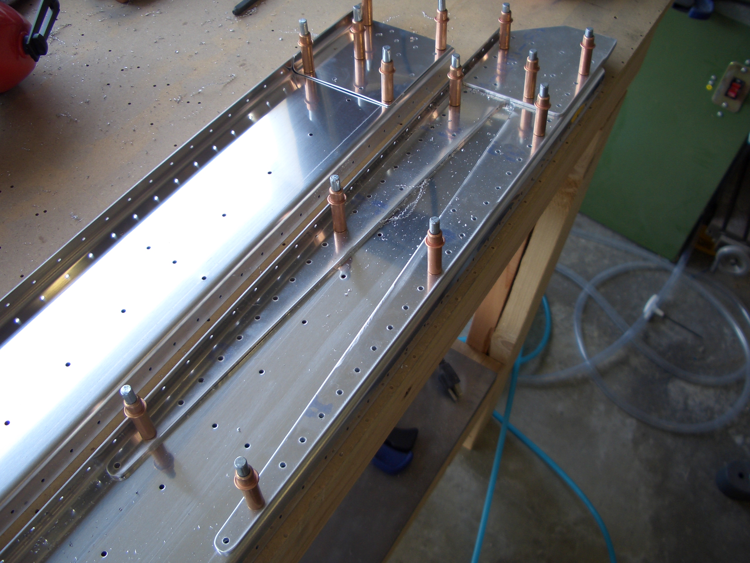
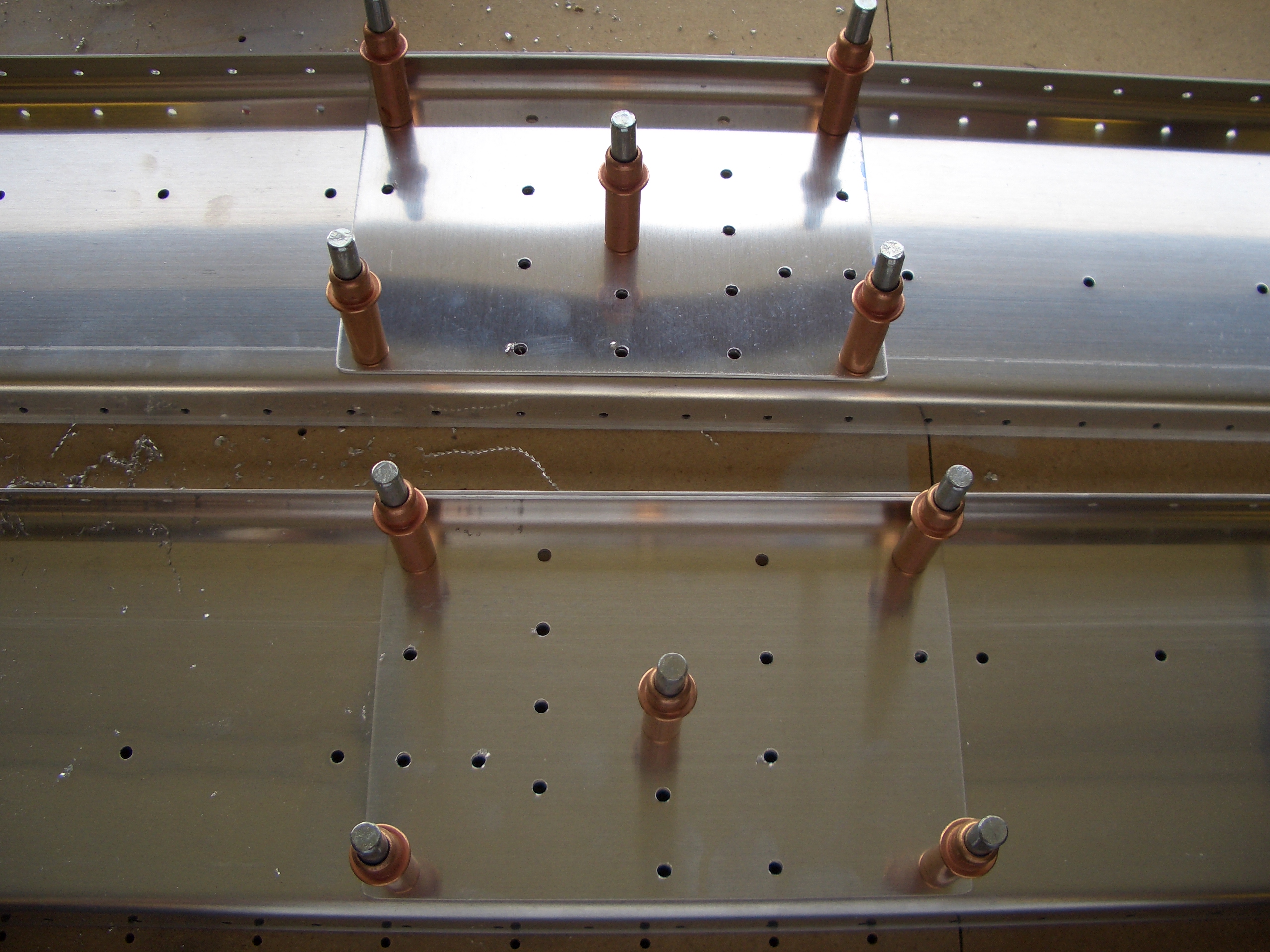
My buddy Andre stopped by today and helped me get started on the wing kit. The first thing you do is install a lot of platenuts. These will be the platenuts that receive the fuel tank screws and inspection cover screws. Here is Andre drilling one of the center holes for the platenuts.
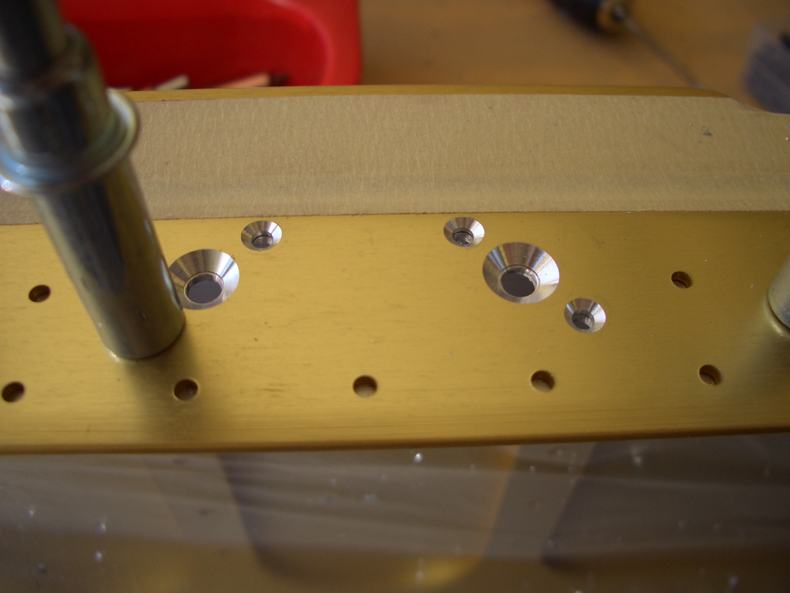
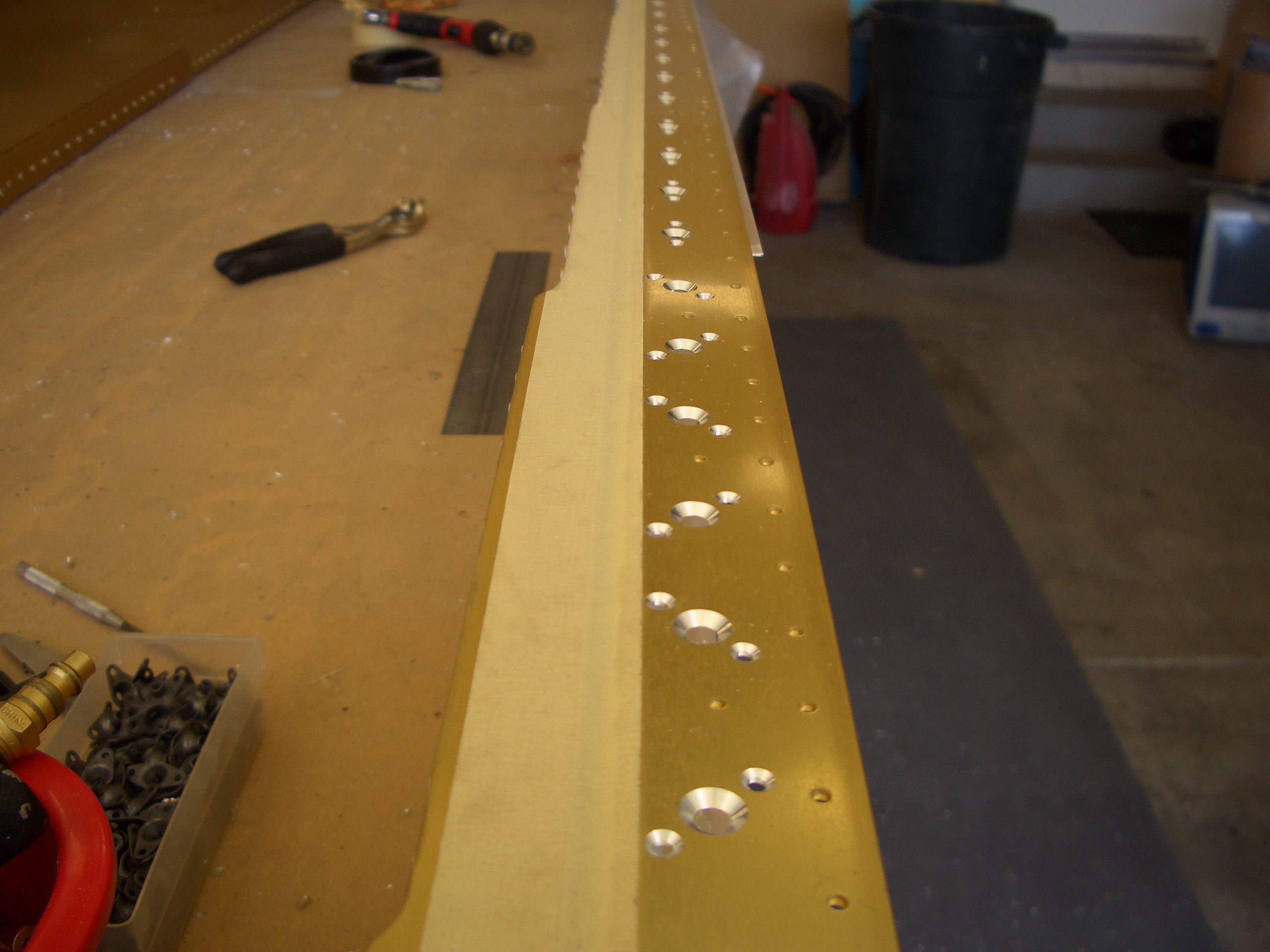
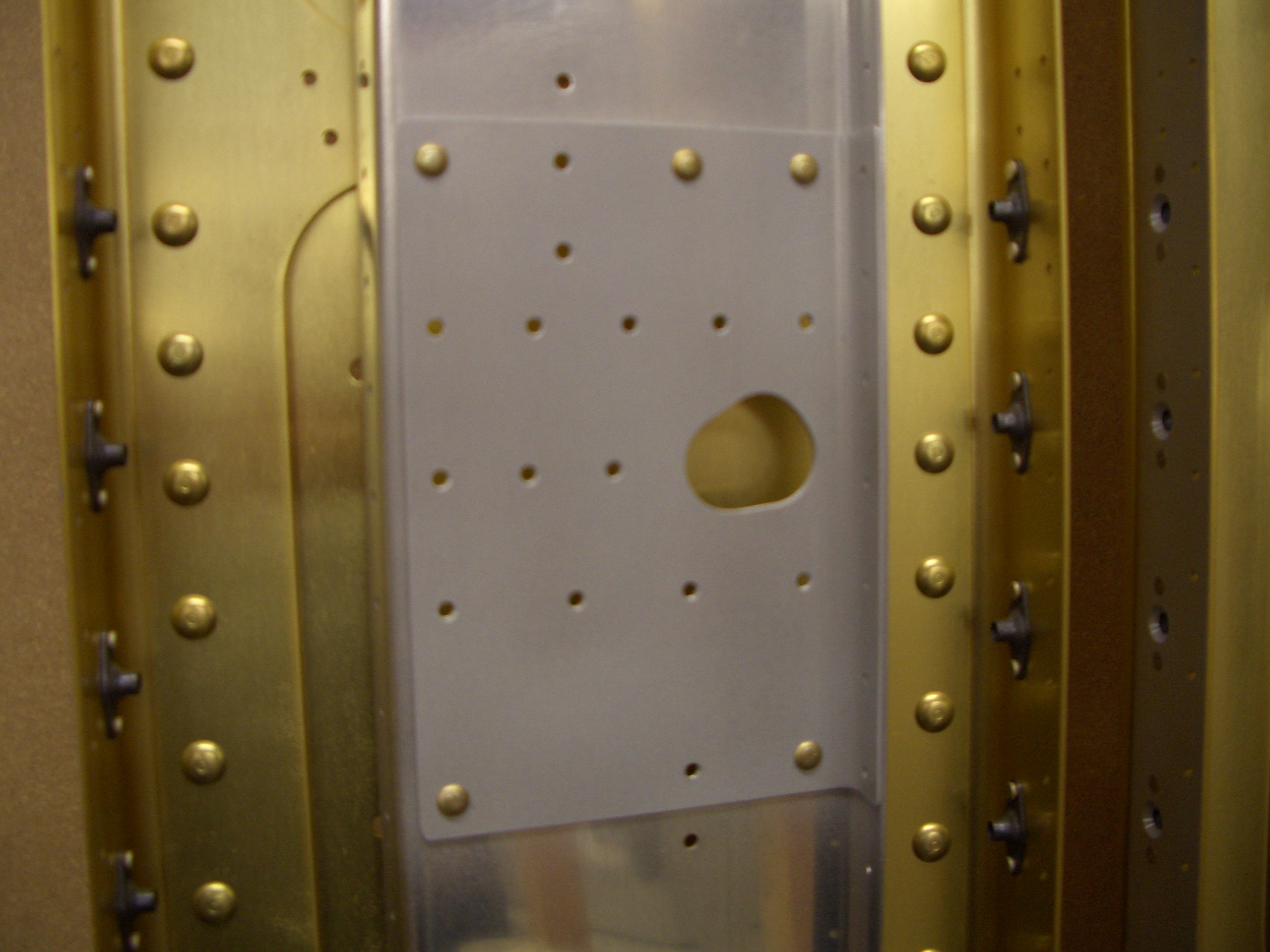
Here you can see the countersinks for a couple of the platenuts. The center hole is countersunk for a #8 screw and the outer holes are countersunk for AD3 rivets.
Here is one completed row of countersinks. Instead of Van’s recommended method of countersinking. I used a long piece of 1/16″ aluminum angle clecoed below the spar flange. Way easier and more precise.
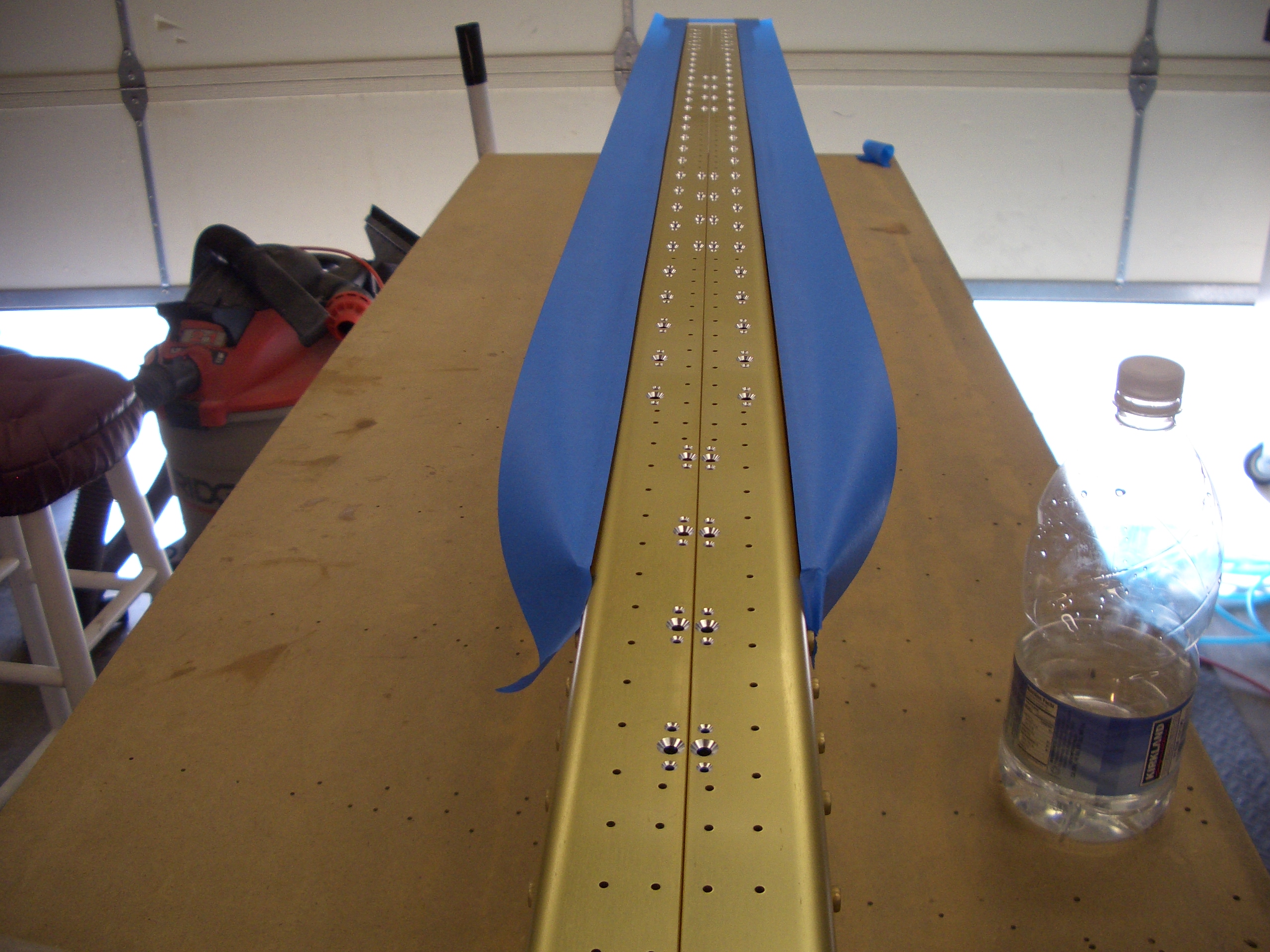
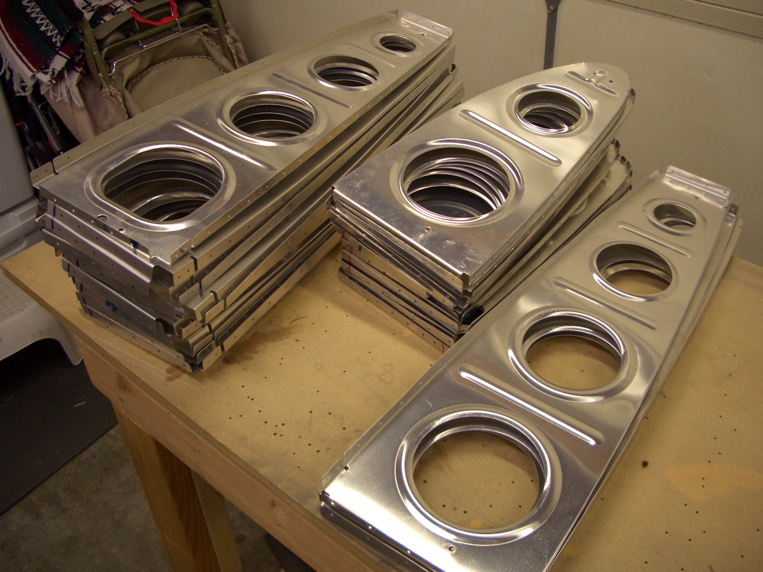
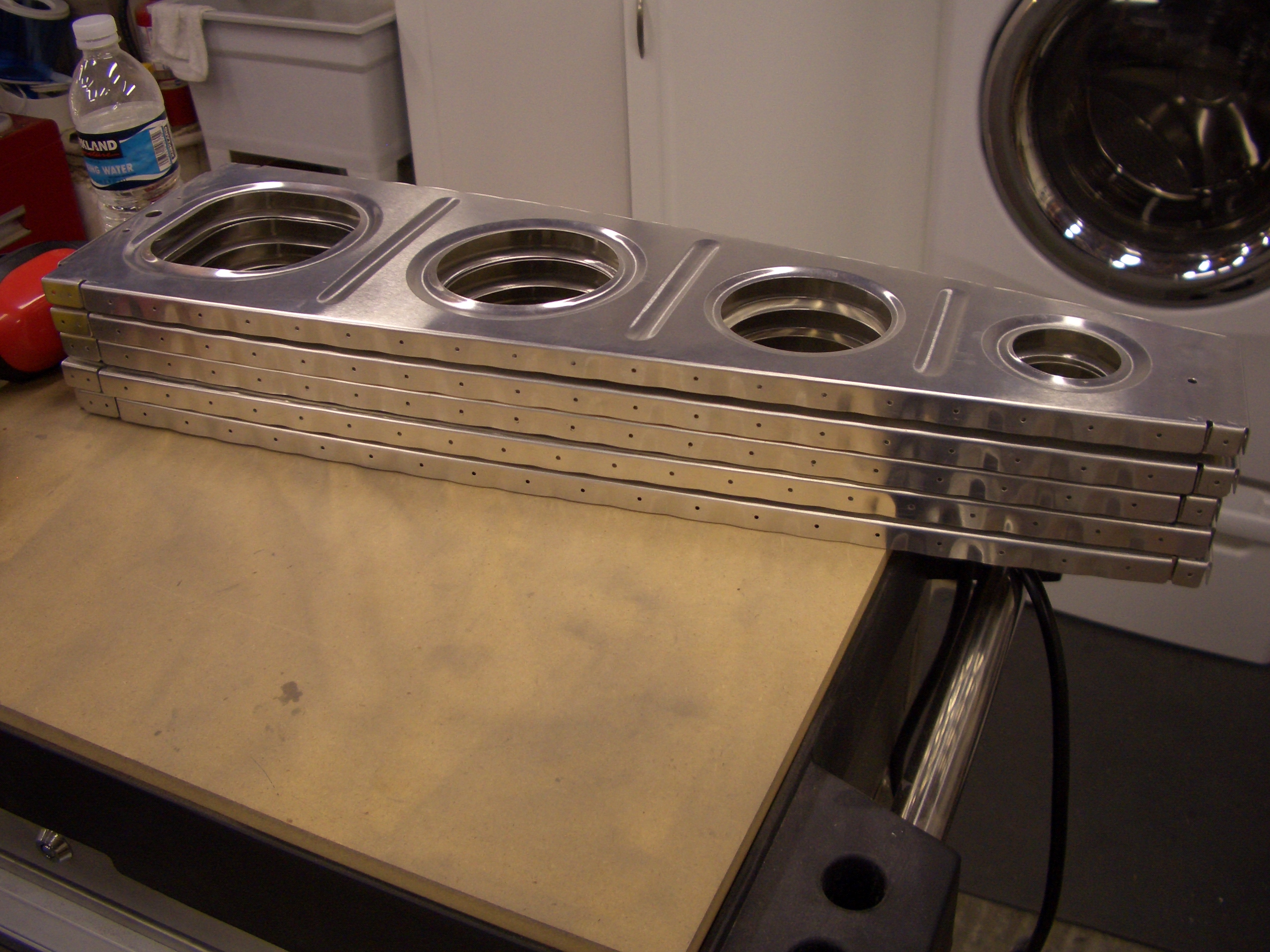
Here are both spars prepped for priming the exposed countersinks.
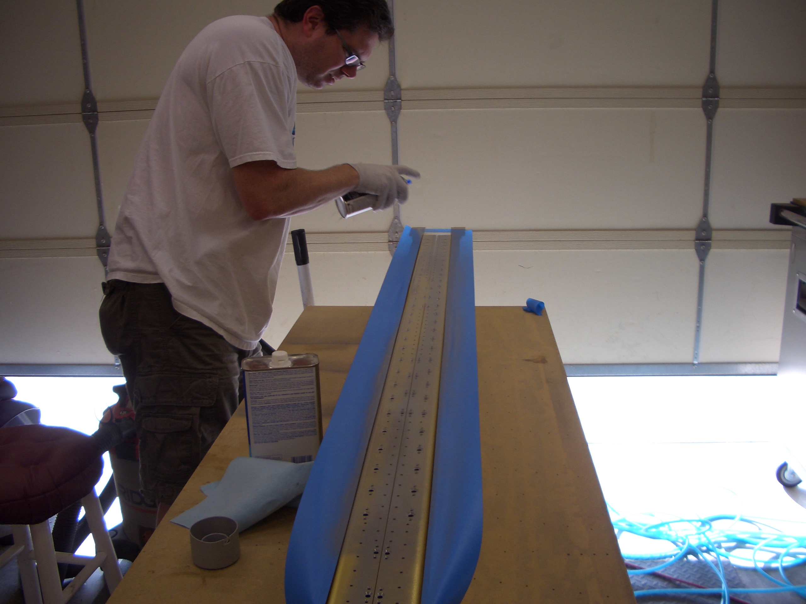
The battery in my digital scale died, so I broke out the NAPA 7220 self-etching primer.
After the primer dried, we installed all of the platenuts. This went surprisingly fast with two of us and we had them all installed in about an hour. Here you can see that the lower platenuts are countersunk for #8 screws and the upper platenuts are not countersunk for the #6 screws in the access plates.

More Spar Platenuts and Tie Down Brackets
I installed two more center section platenuts per spar. Given that I was alone today, I shot and bucked these solo. They turned out pretty good.
I also tapped the tie down brackets. Apparently, many builders have trouble with this, but mine turned out great and only took about 15 minutes.
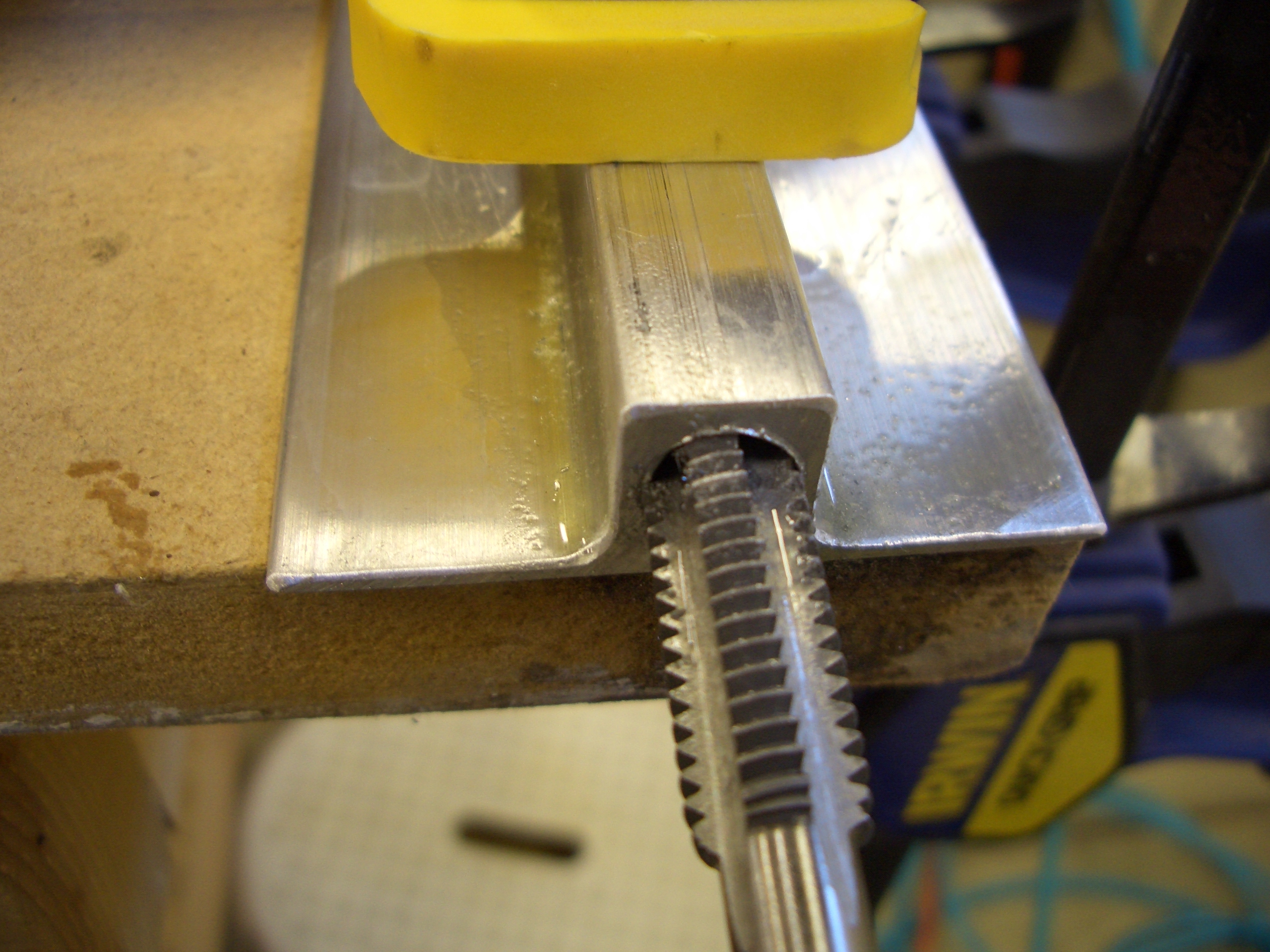
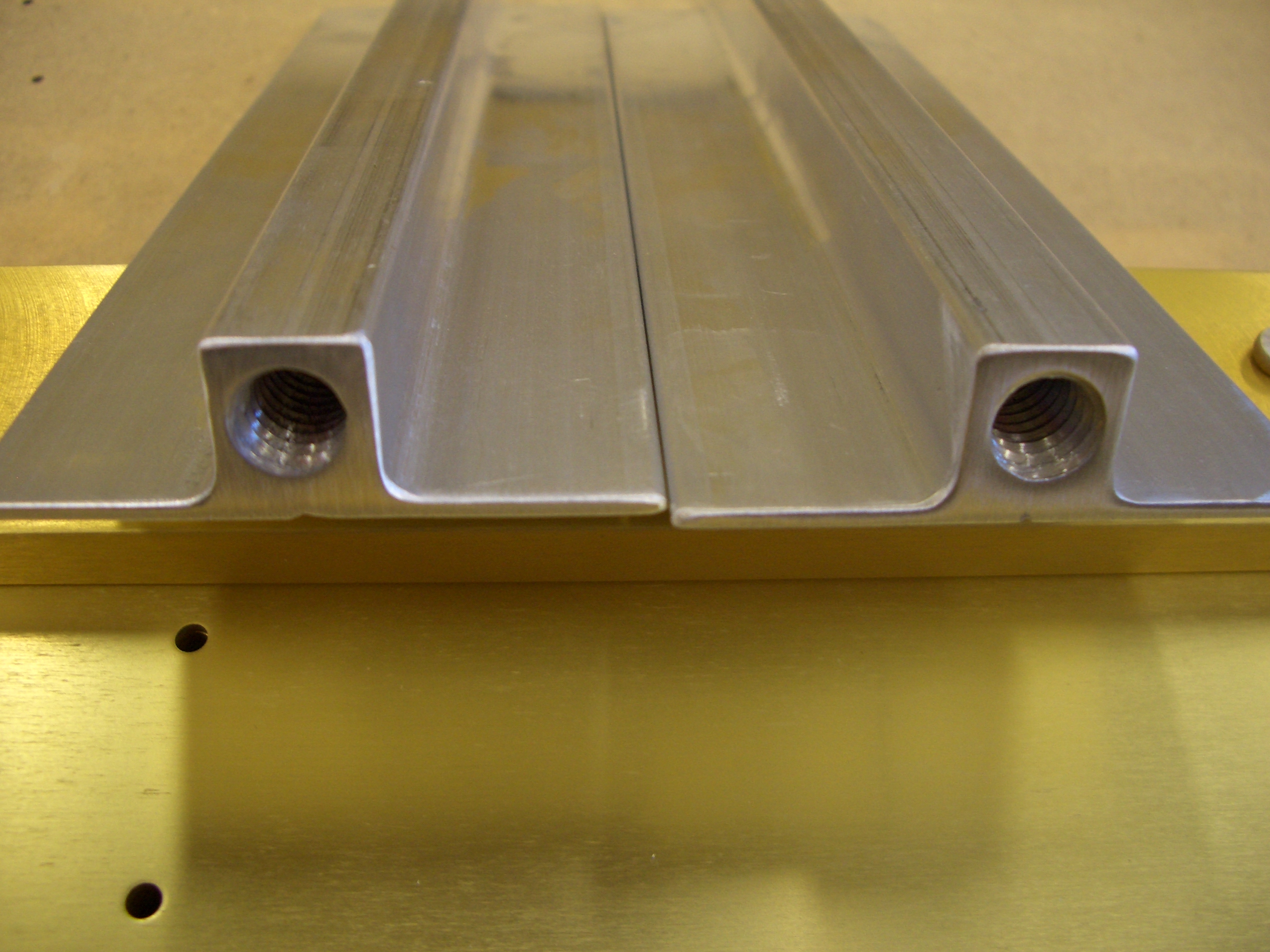
Here are both tie down brackets with their threaded ends.
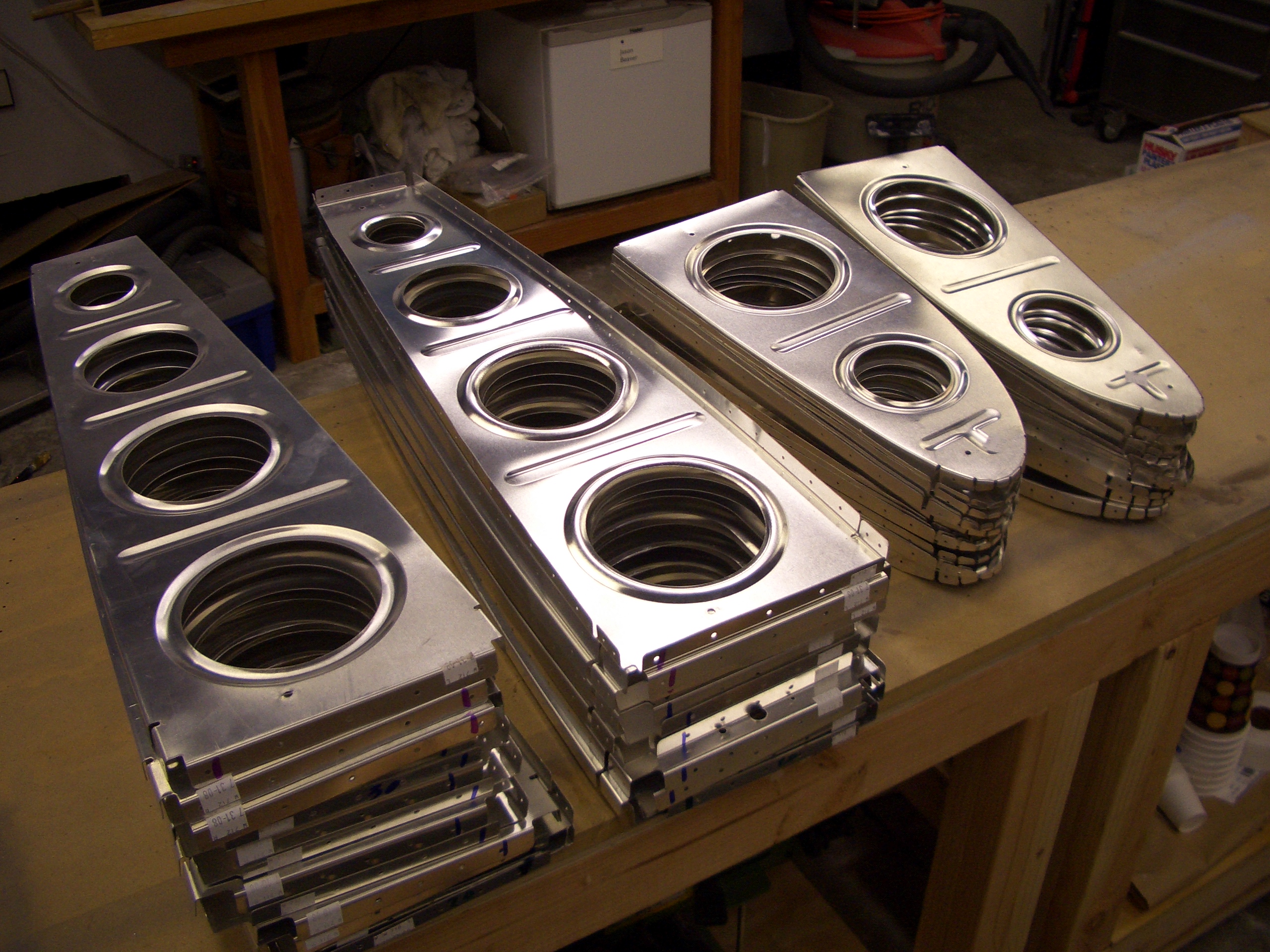
Finished Main Spars
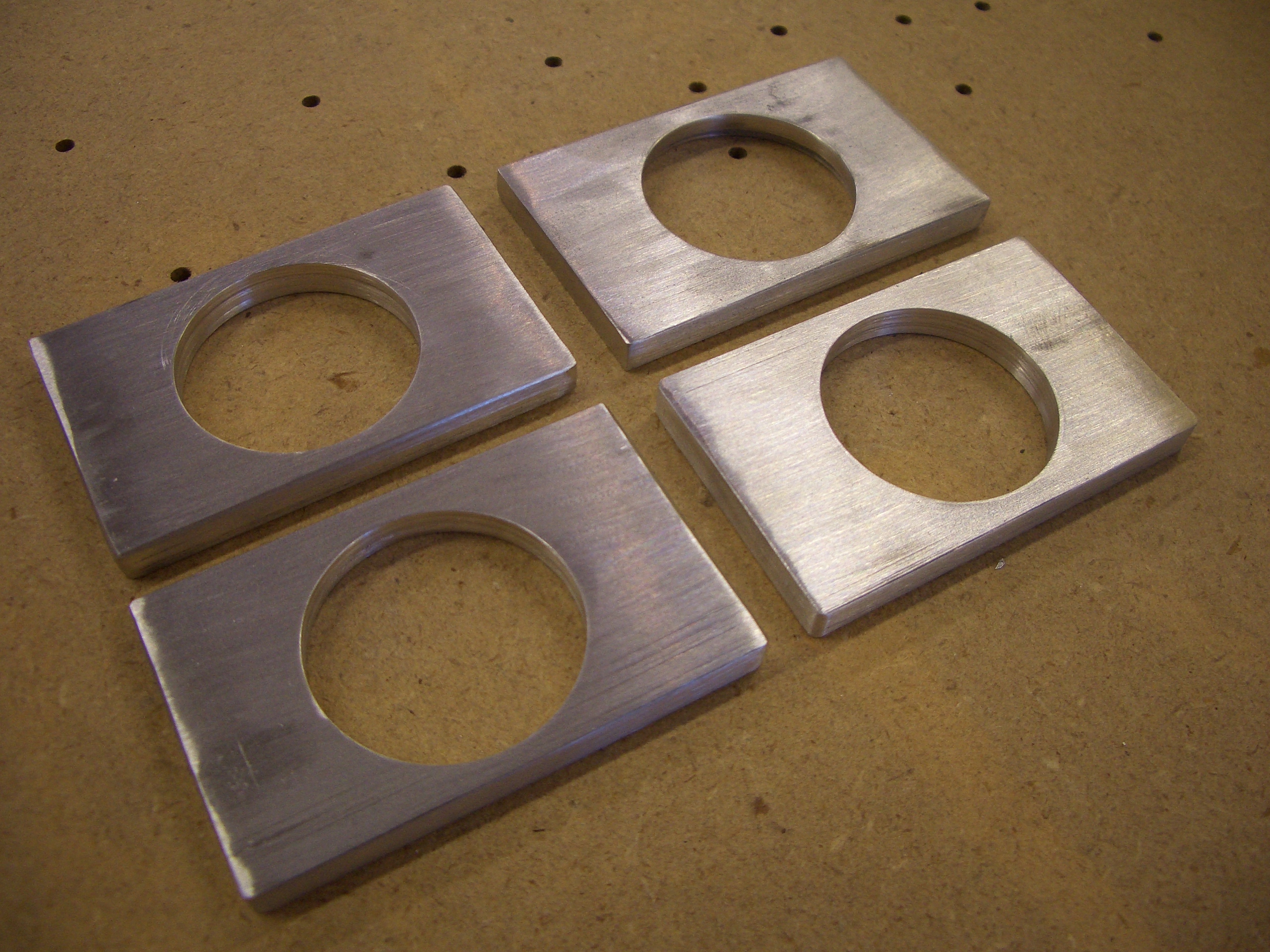
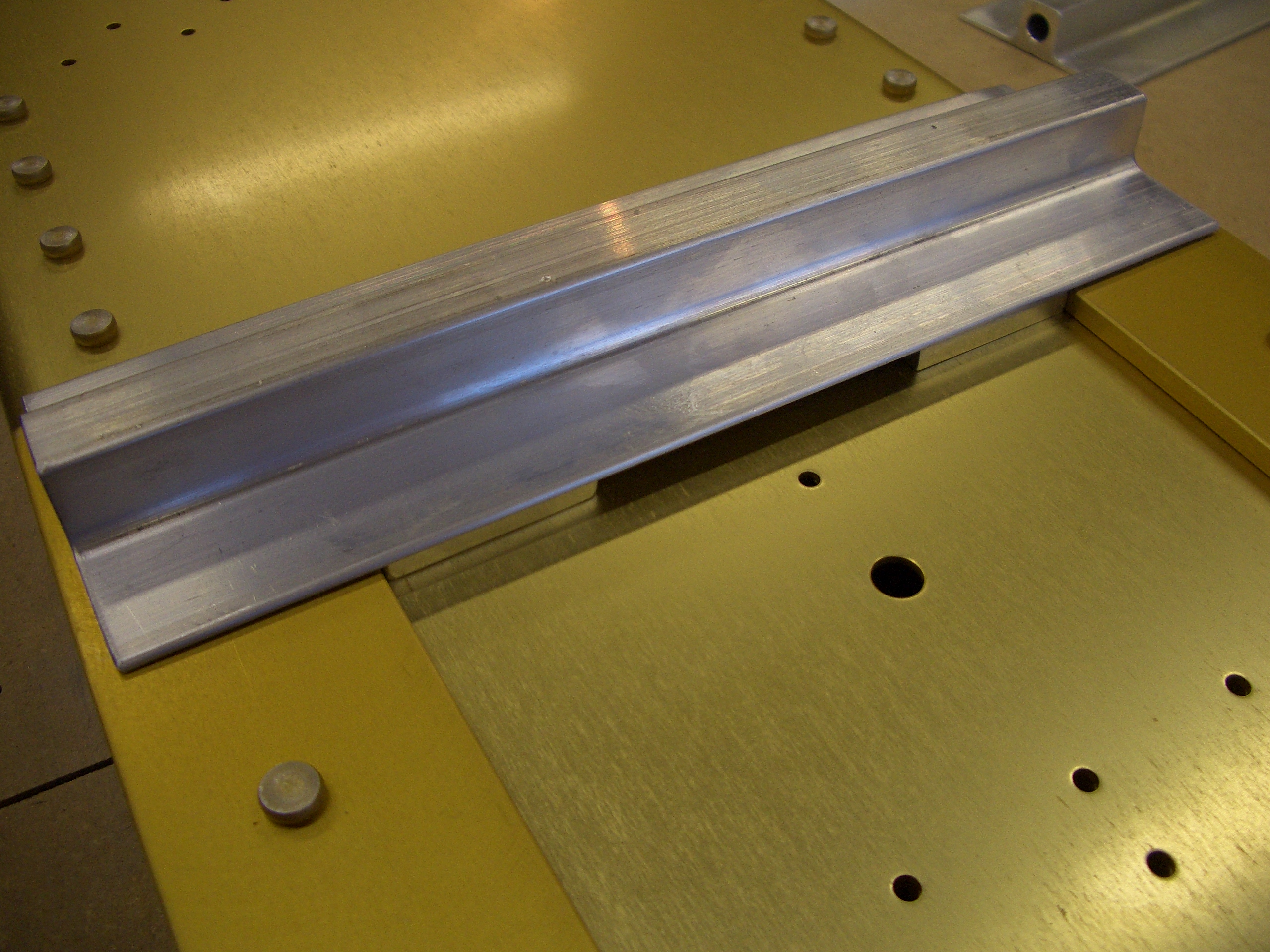
I got started making the tie down bracket spacers. The crappy harbor freight hole saw and fly cutter I had sucked, so I went to Lowes and picked up a bi-metal 1″ hole saw to make these holes.
Here is where the spacers will sit on the spar.
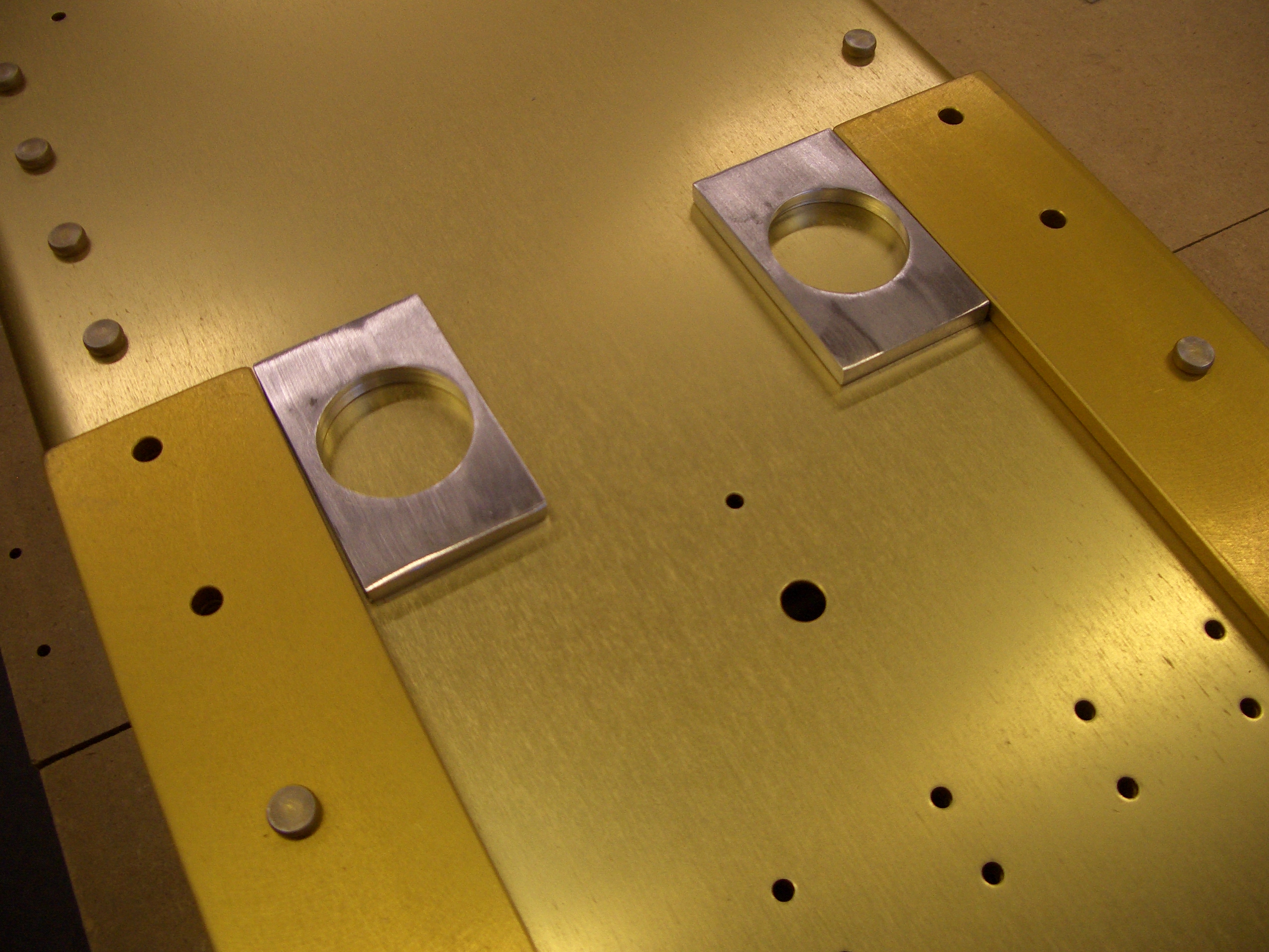
And here is how the tie down bracket will sit on top of them.
The spacers are back-drilled through the holes in the spar and then holes for nutplates are drilled. Here are all of the parts primed and riveted together.
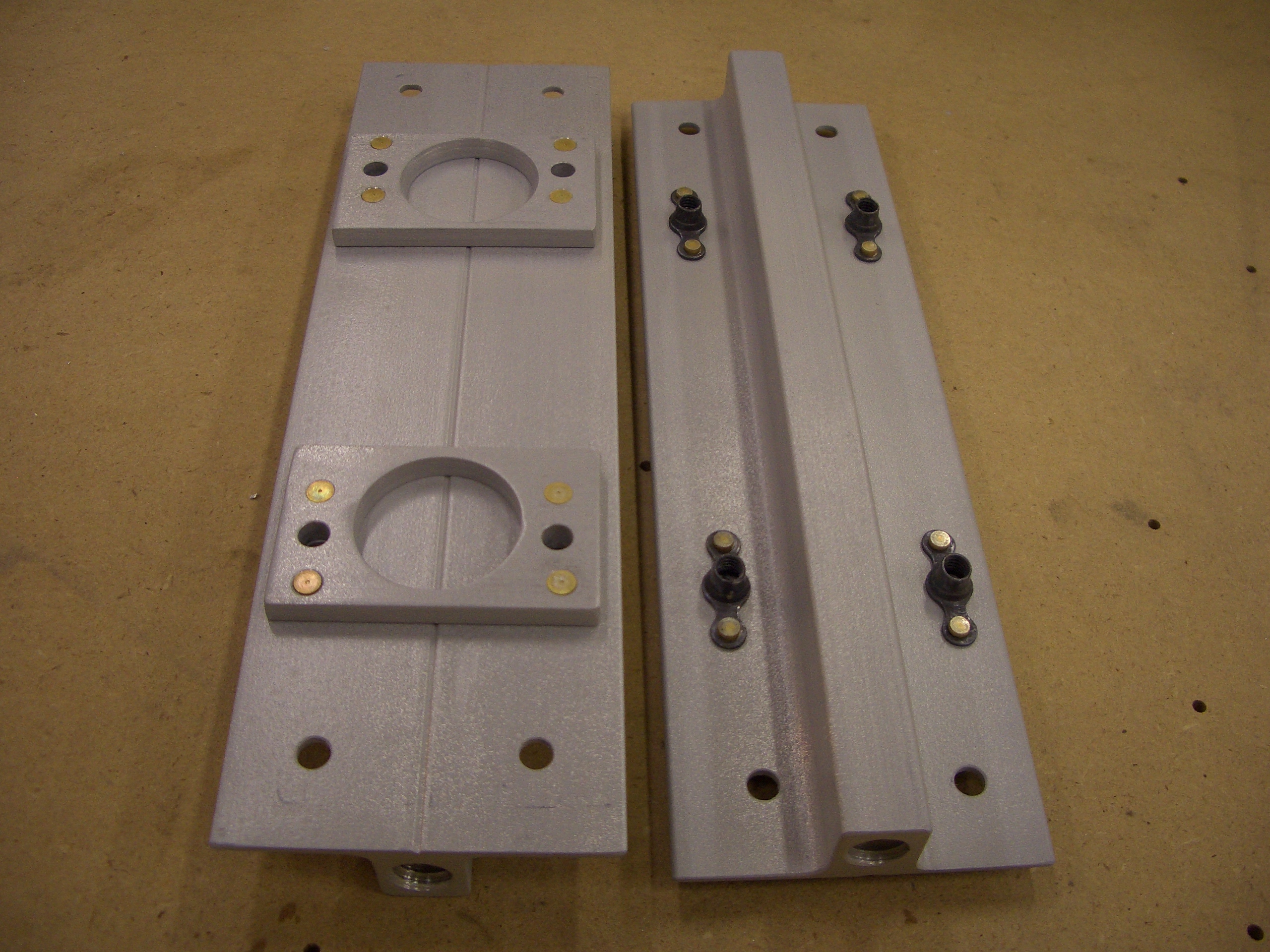
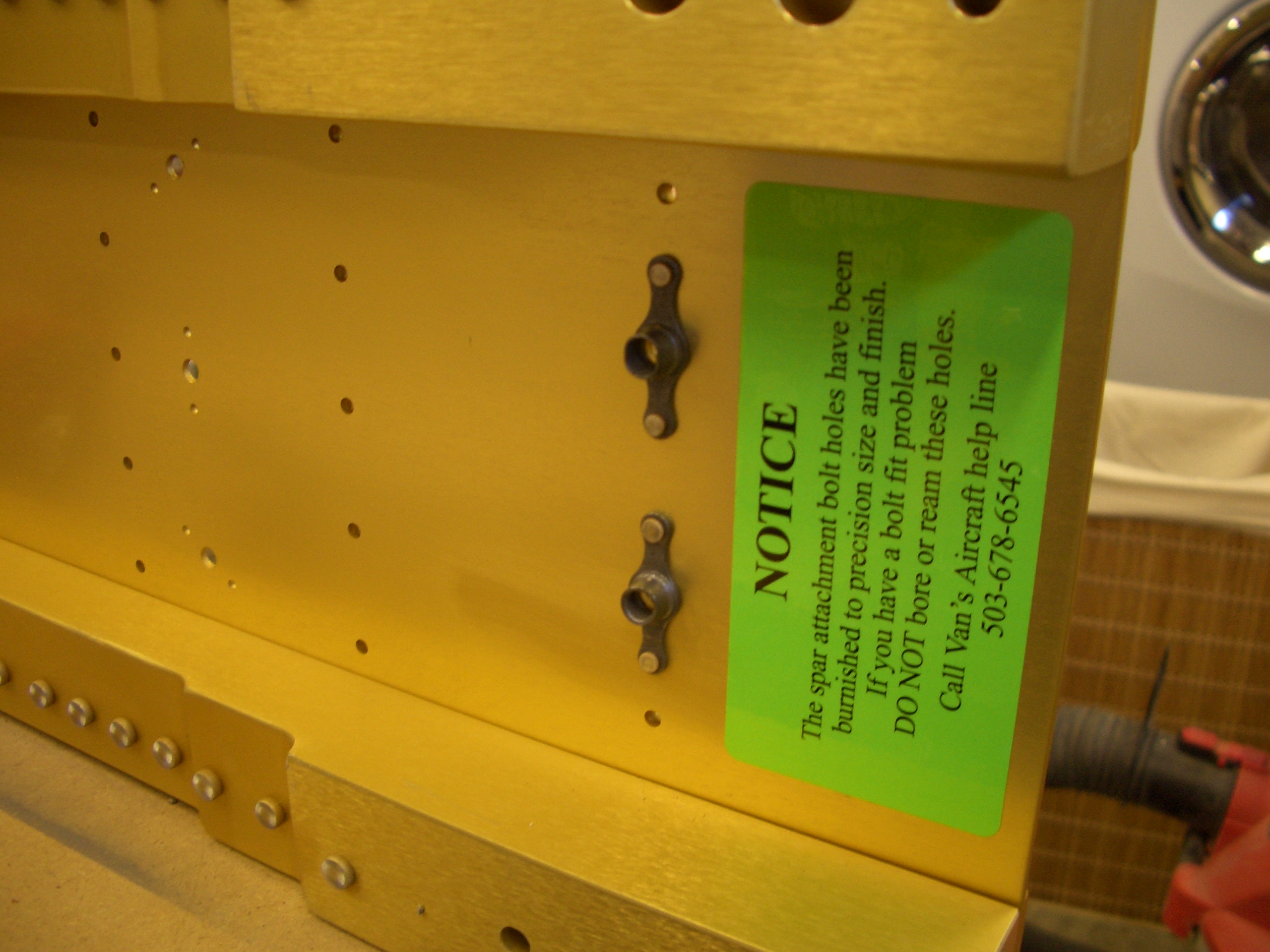
And here they are installed and torqued to the spar.
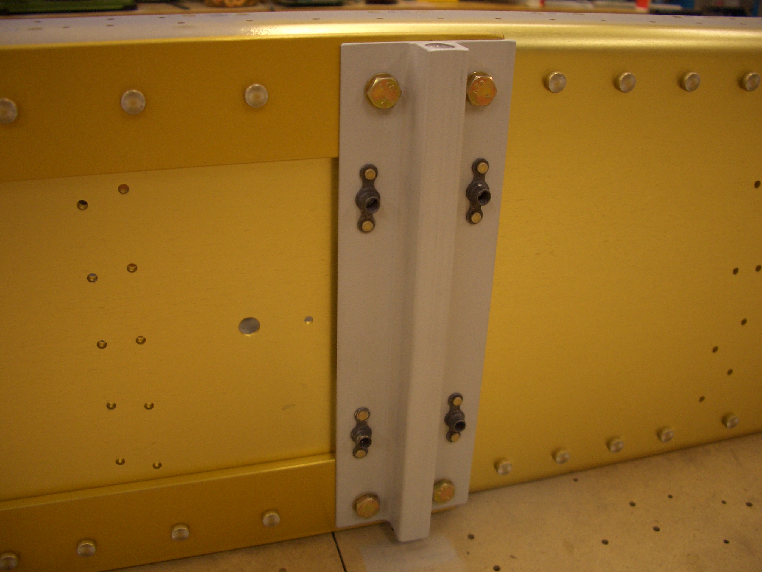
The backside of the spar showing the nuts holding these on. The four hole in the middle bo through the spacers and line up with the nutplates. These will be used for mounting the aileron bellcrank brackets.
Identified Wing Ribs
I took the time tonight to identify and mark all wing ribs. This was a surprisingly time-consuming process because there are three types on main ribs (on the left) and four types of leading edge ribs (on the right), and all of these come in left-handed and right-handed variants. Also, each wing has a mix of the left and right-handed variants and they don’t follow any simple pattern. Basically, you have to study the plans and make sure you’re using the right rib in the right spot. I have all of these stamped now, and I’ve double checked them, so it will be easy when it comes time to attach these to the spar.
Worked on Rear Spar
I began working on the rear spar. I started by trimming the inboard ends of rear spar reinforcing fork and doubler plates. I don’t have a picture of it, but there is a bit of metal that has to be removed when building the RV-7/RV-7A.
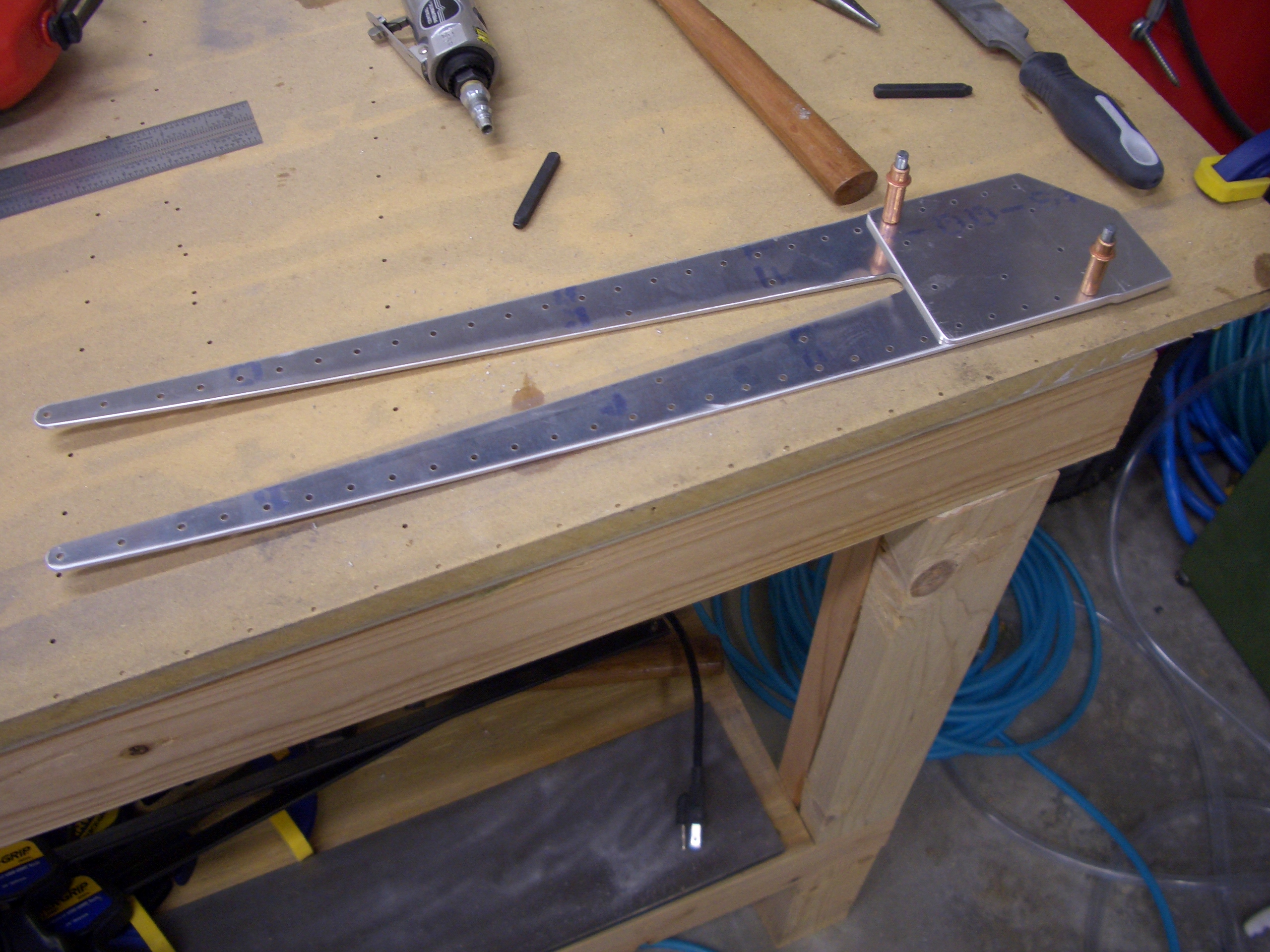
Here are the rear spars. I’ve just clecoed the center reinforcing plate on the upper one.
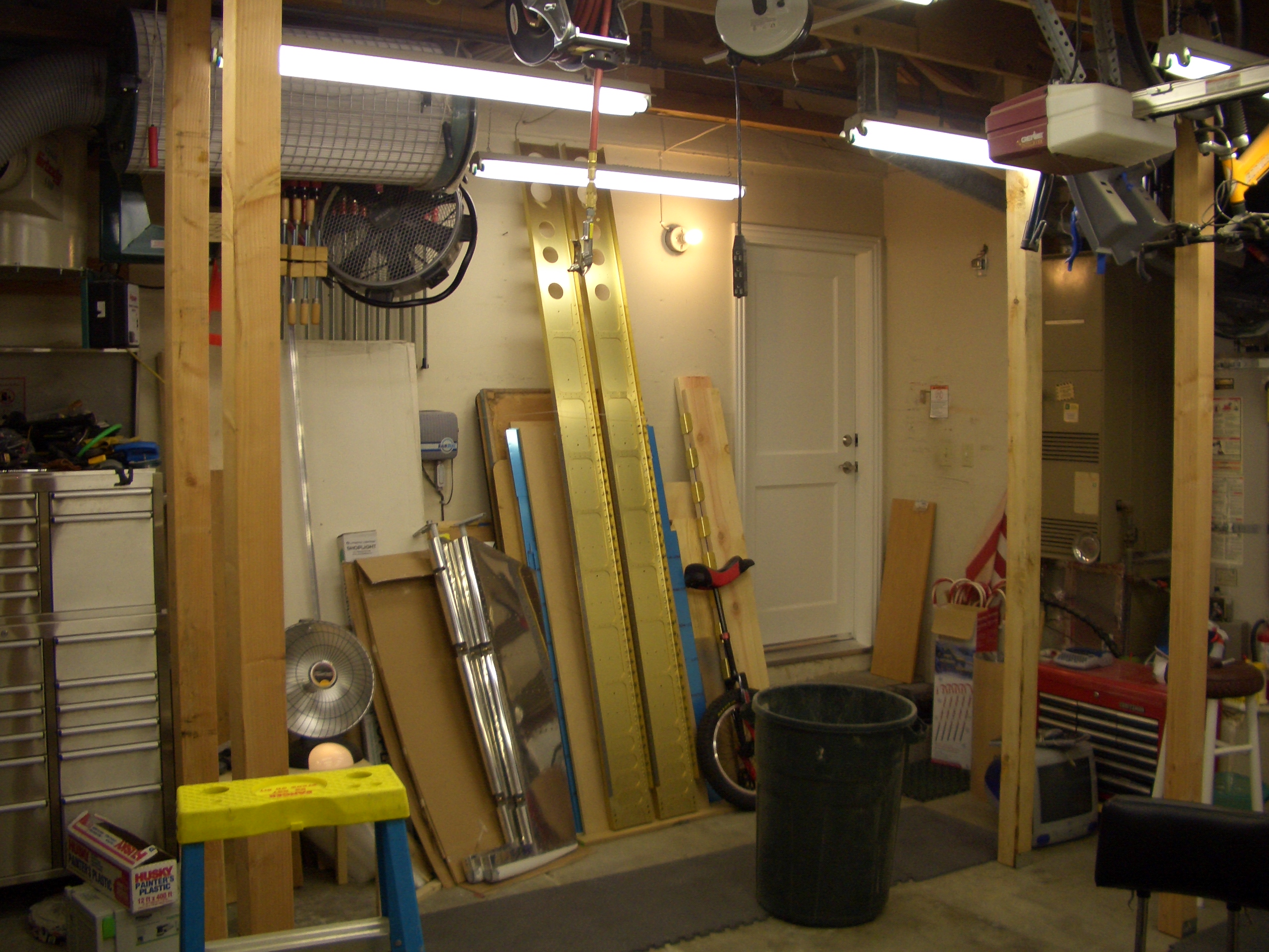
My brother is in town and helped me erect the wing jig. I’m going to build both wings at the same time when possible, so I’ve erected two pairs of 4x4s about 2 feet apart.
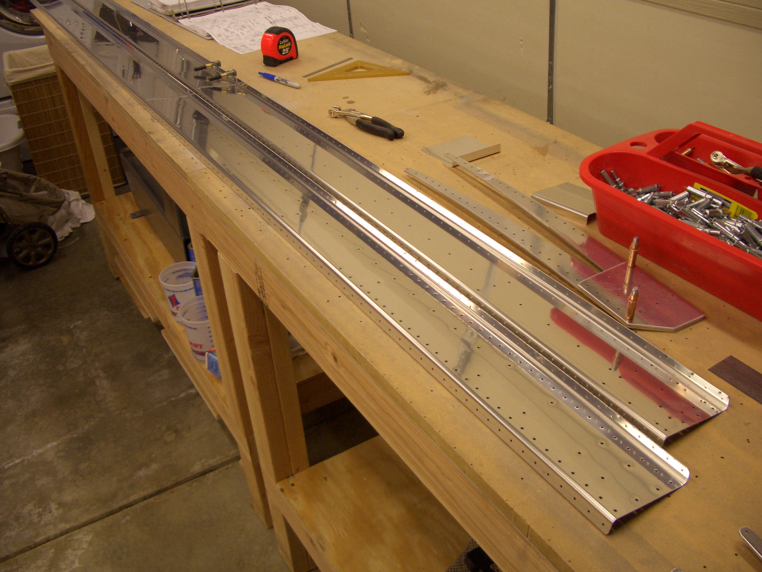
Continued Work on Rear Spar
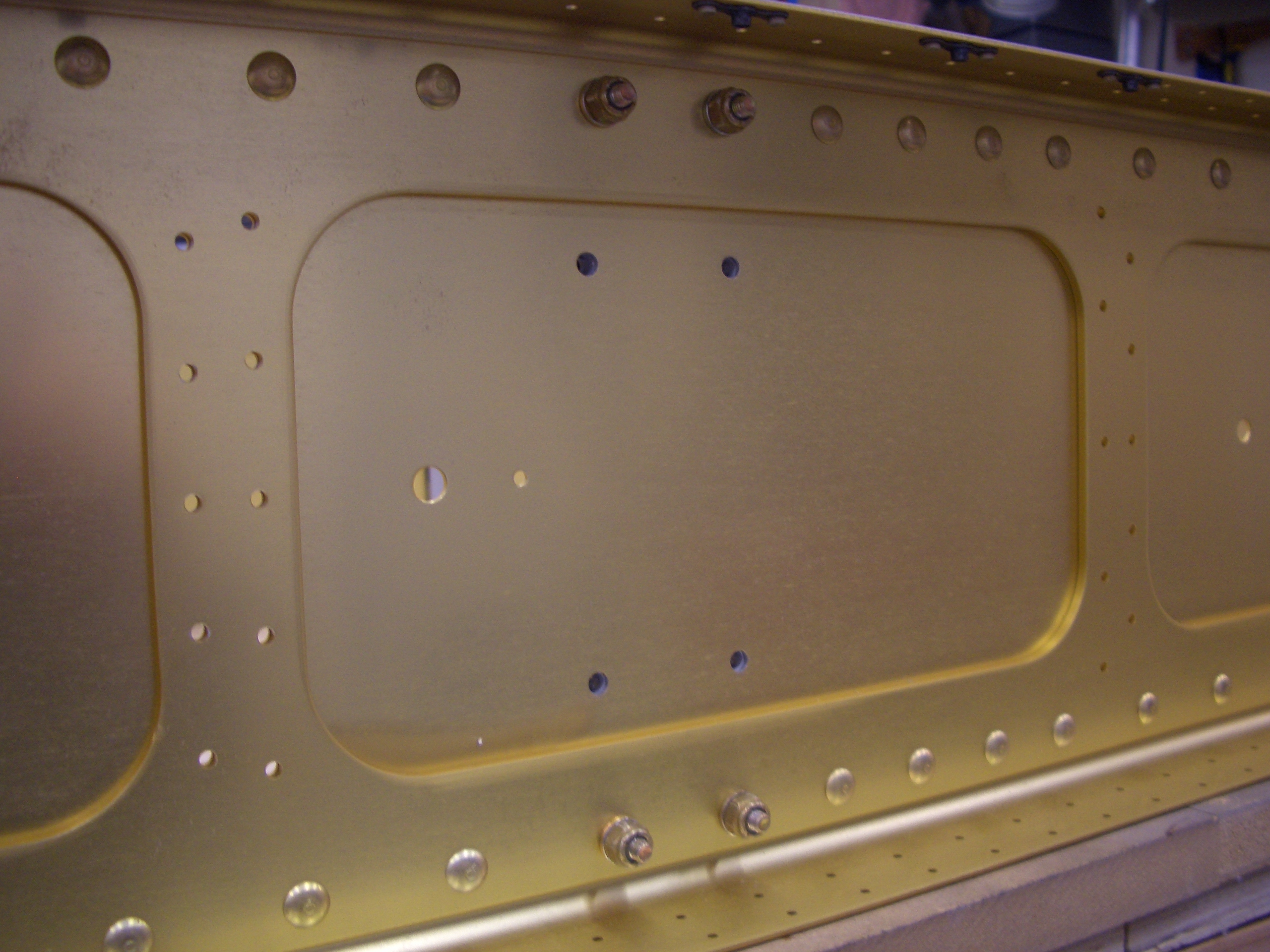
I clecoed all of the reinforcing plates and doubler plates onto the spar and match drilled them to the spar.
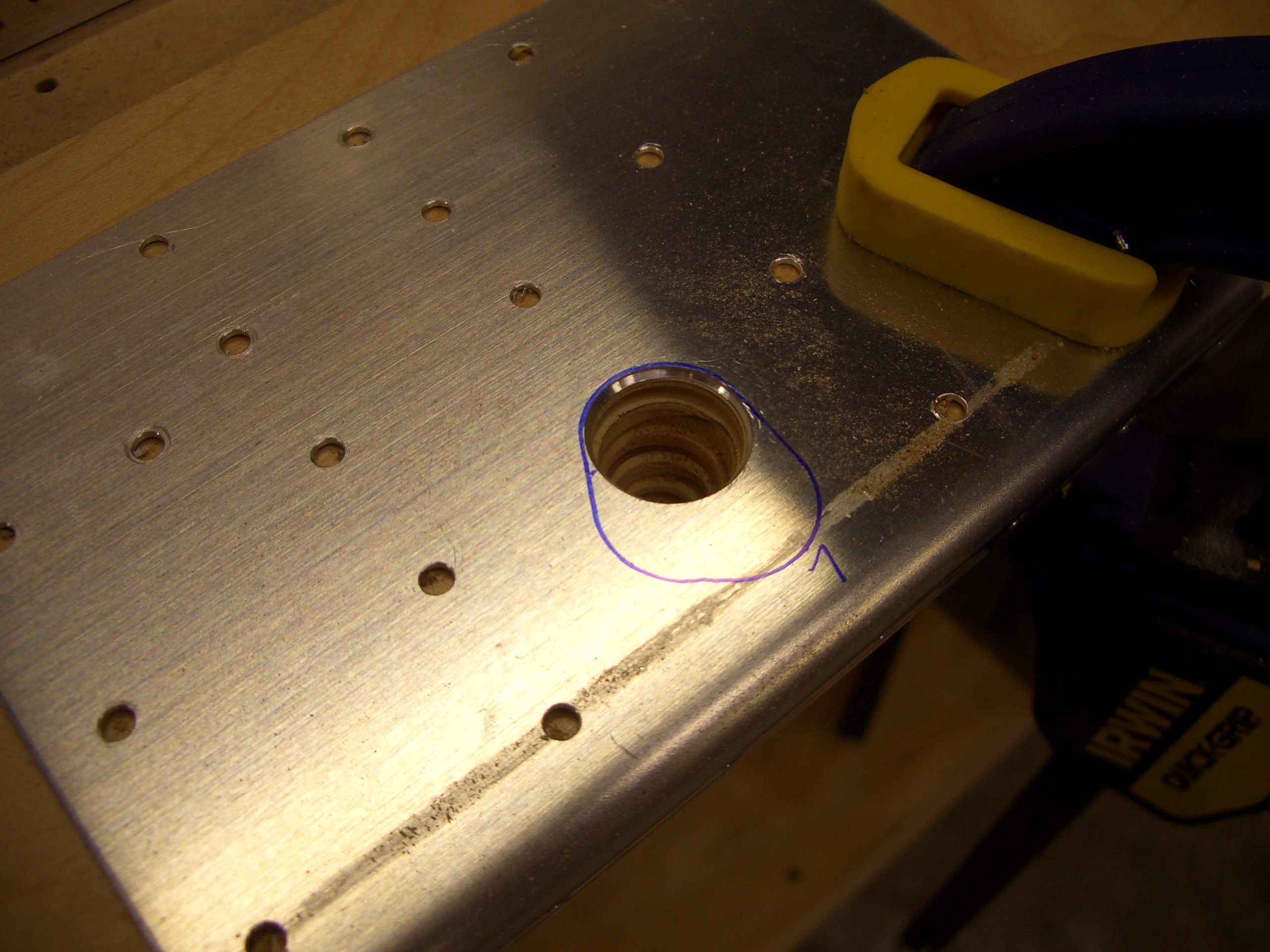
Here are the center reinforcement plates match drilled. I hadn’t noticed the missing hole when I took this shot (can you spot it).
The reinforcing plates have to have an odd shaped hole for the aileron pushrod to go through. This hole is already punched in the spar but must be cut in the reinforcing plate. I used a unibit to rough cut close to the line and then files and sanded until they matched.
Afterward, I prepped and primed the reinforcing plates and doublers and riveted them to the spars. Look carefully at the rivet callouts. There are many rivets that are skipped and several different rivet lengths.
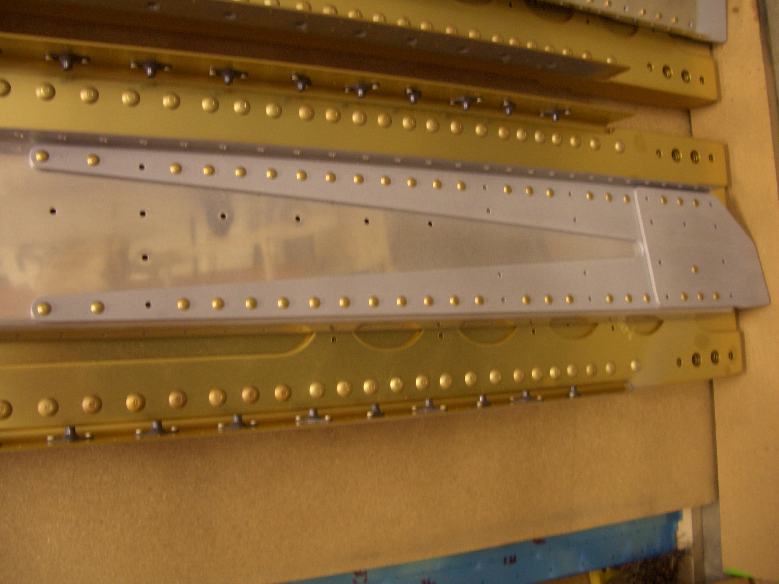
Here is the center reinforcing plate. All of the missing rivets will be installed later in conjunction with other components.
Prepping Wing Ribs
I’m in the middle of prepping the wing ribs. There are 54 ribs total, and each one has to have the flanges bent to 90º and fluted between each hole to let them lay flat. I still need to debur the lightning holes and edges before they can be attached to the spars. This is a really time-consuming process, and I’m not even halfway through the process yet.
Here are some of the main ribs and prepping the flanges. You can see how straight they are compared with the picture above.
Here is a close-up of the flutes that are added between each hole. Basically, the edge of the flange is longer than the portion of the flange next to the web when the flange is curved. This causes the rib to bow away from the flange. By fluting the flanges, you effectively shorten the edge to be the same length as the flange along the web allowing the rib to lay flat. This is definitely something you just have to get a feel for. I’m getting faster, but it still takes 5-10 minutes per rib.