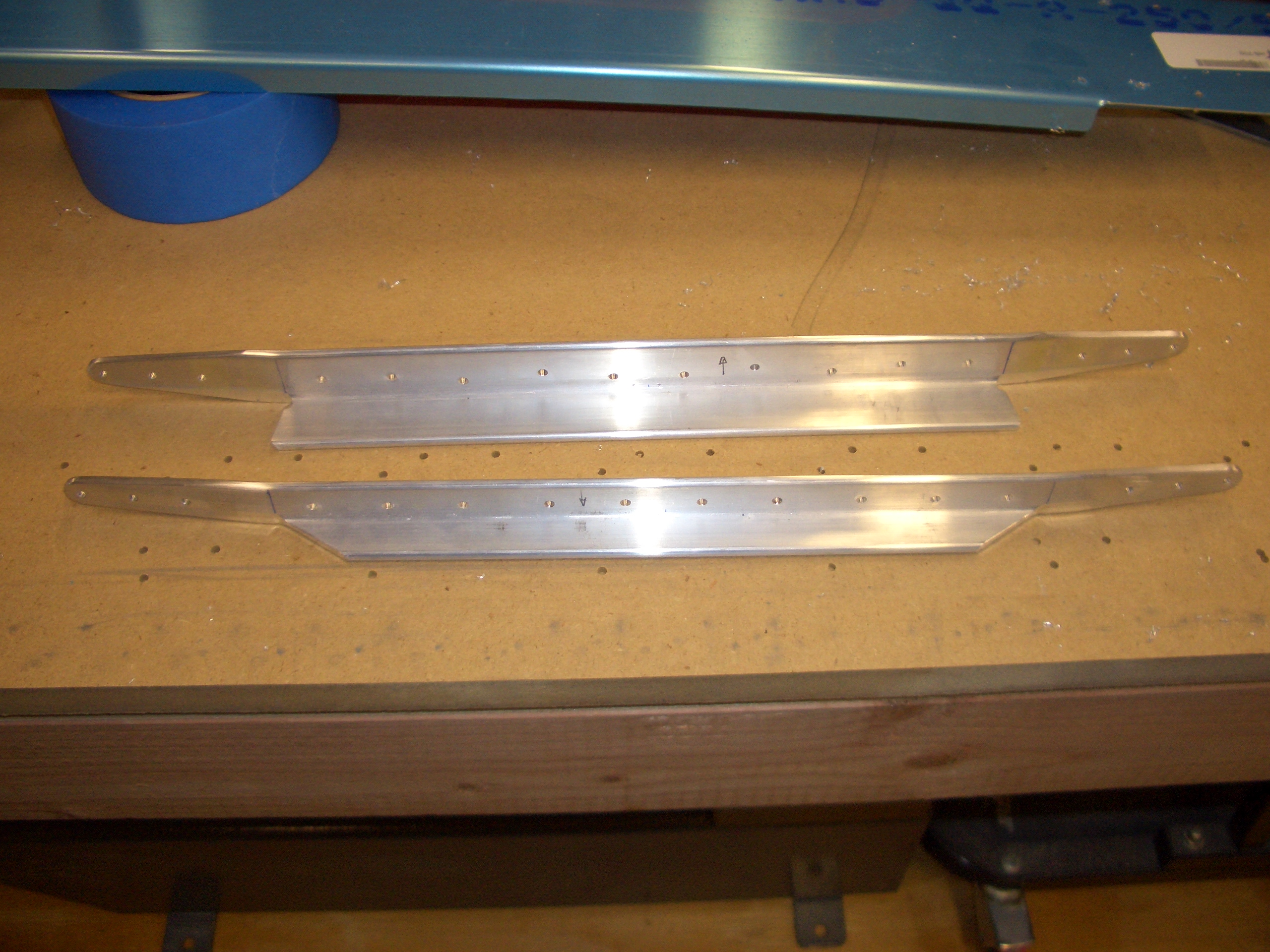
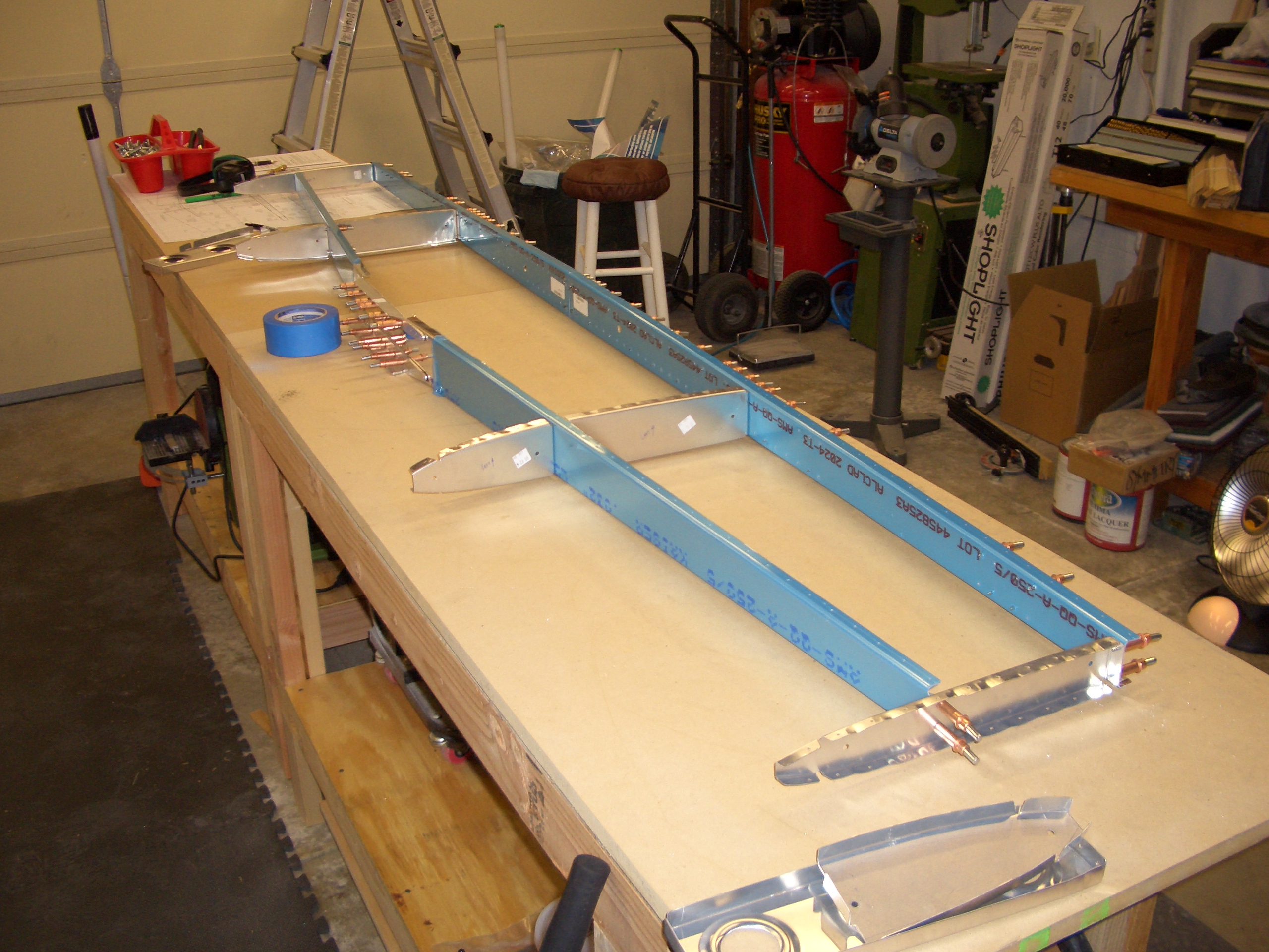
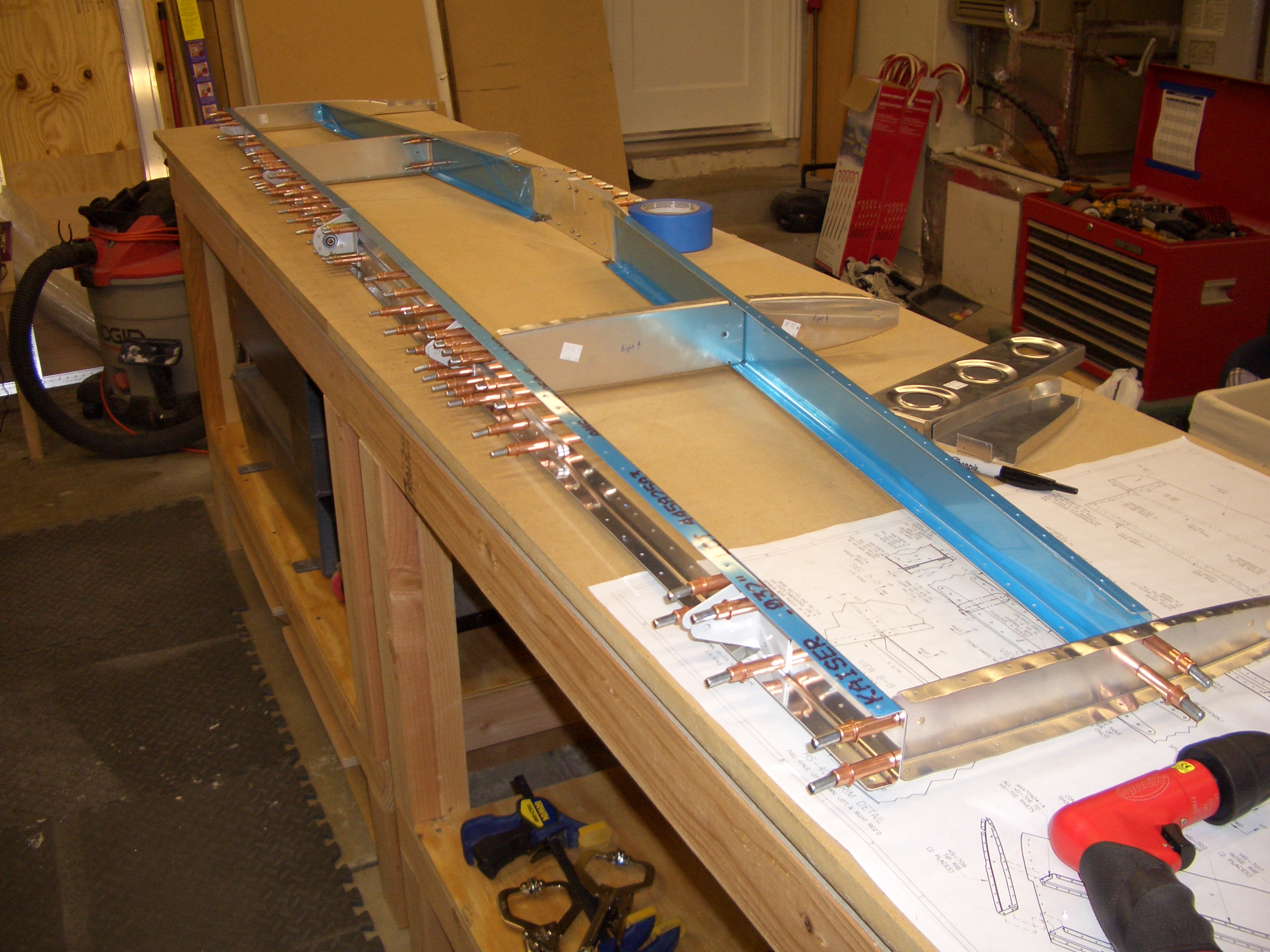
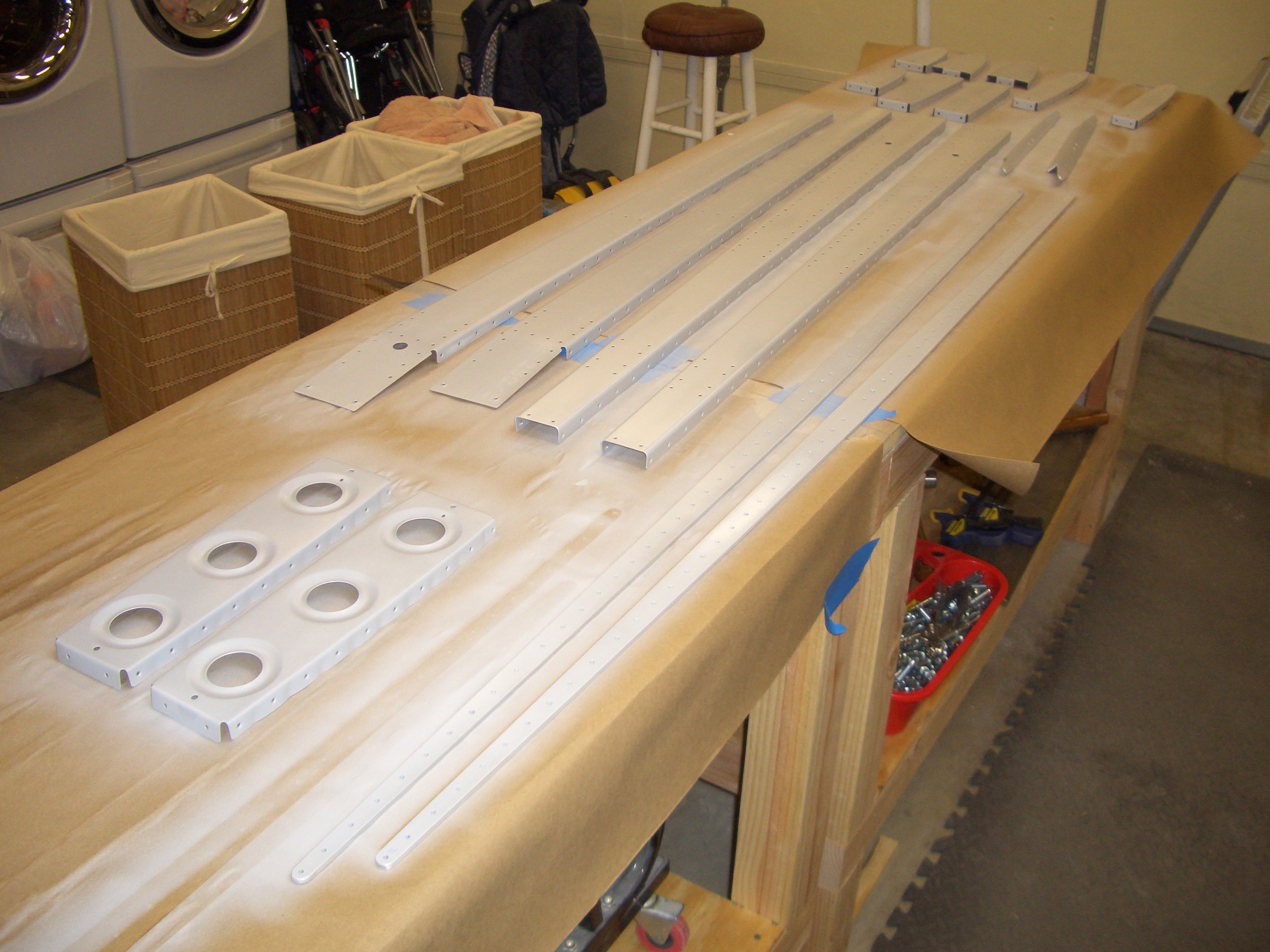
After fluting and straightening HS-405, I match drilled it to the rear spar in preparation for drilling it in conjunction with the skin.

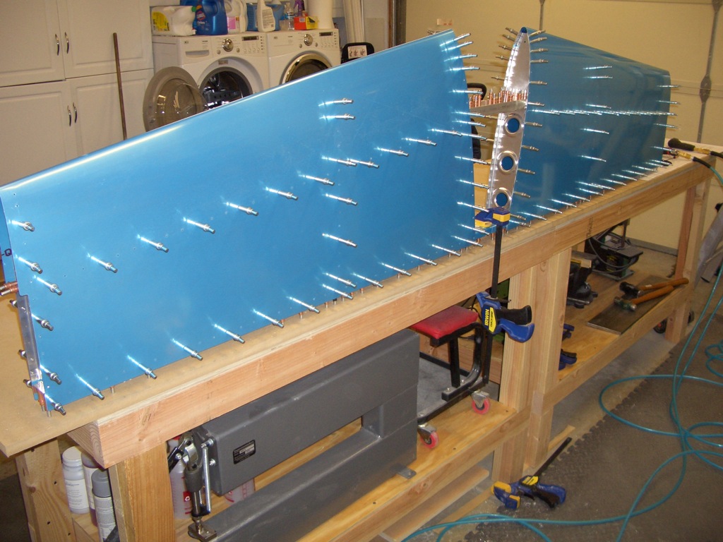
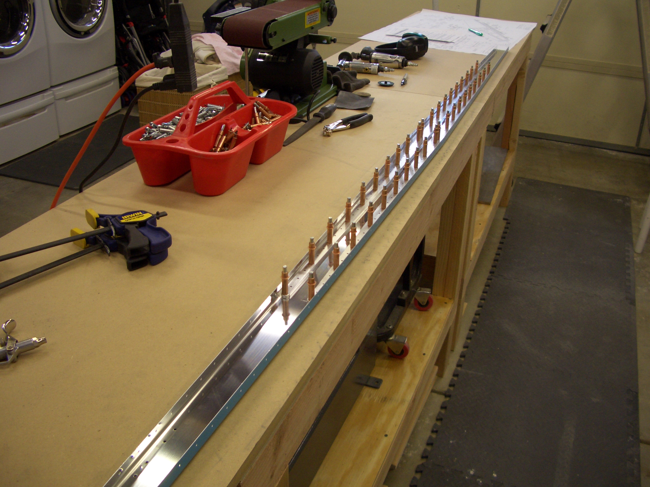
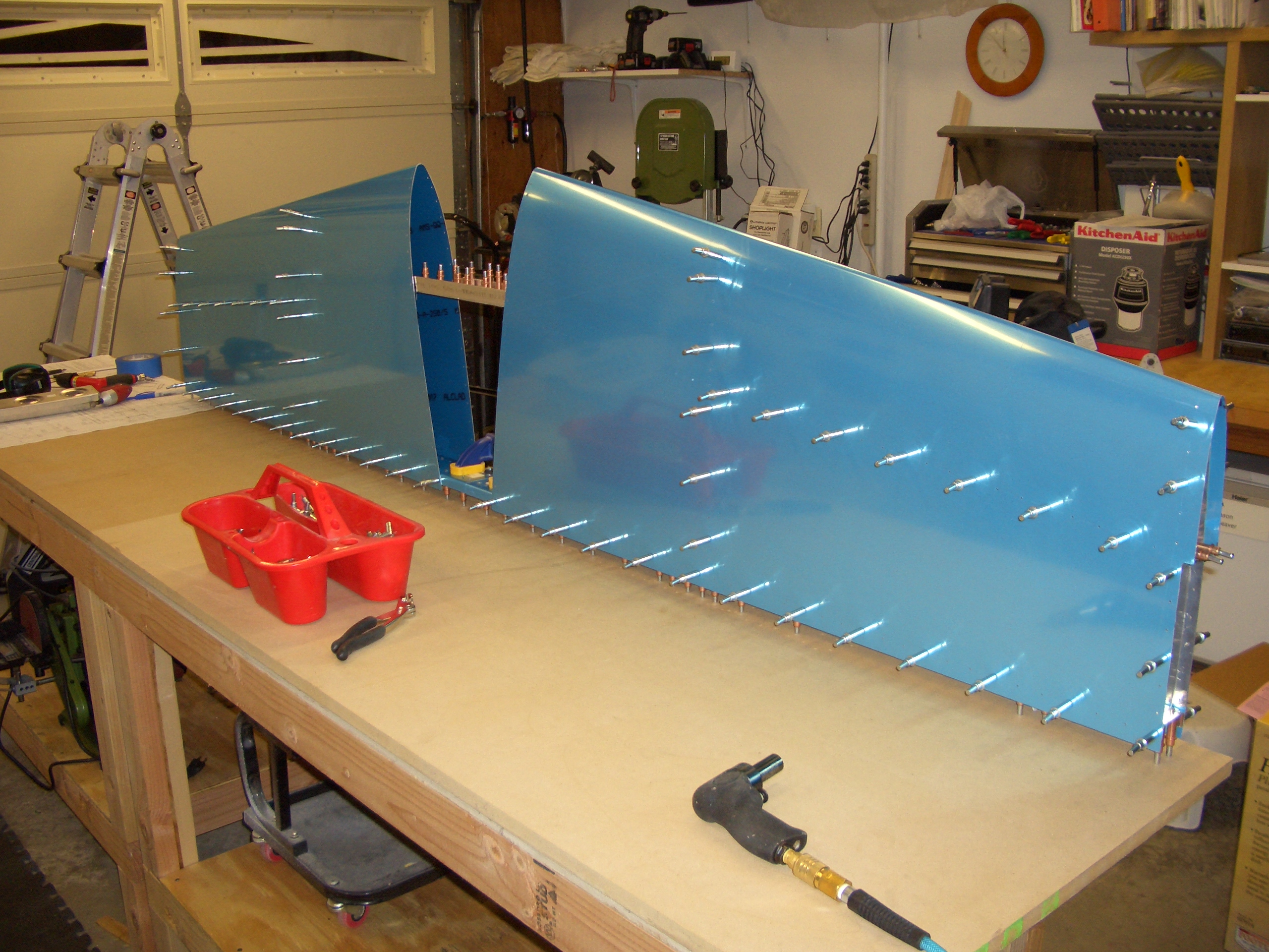
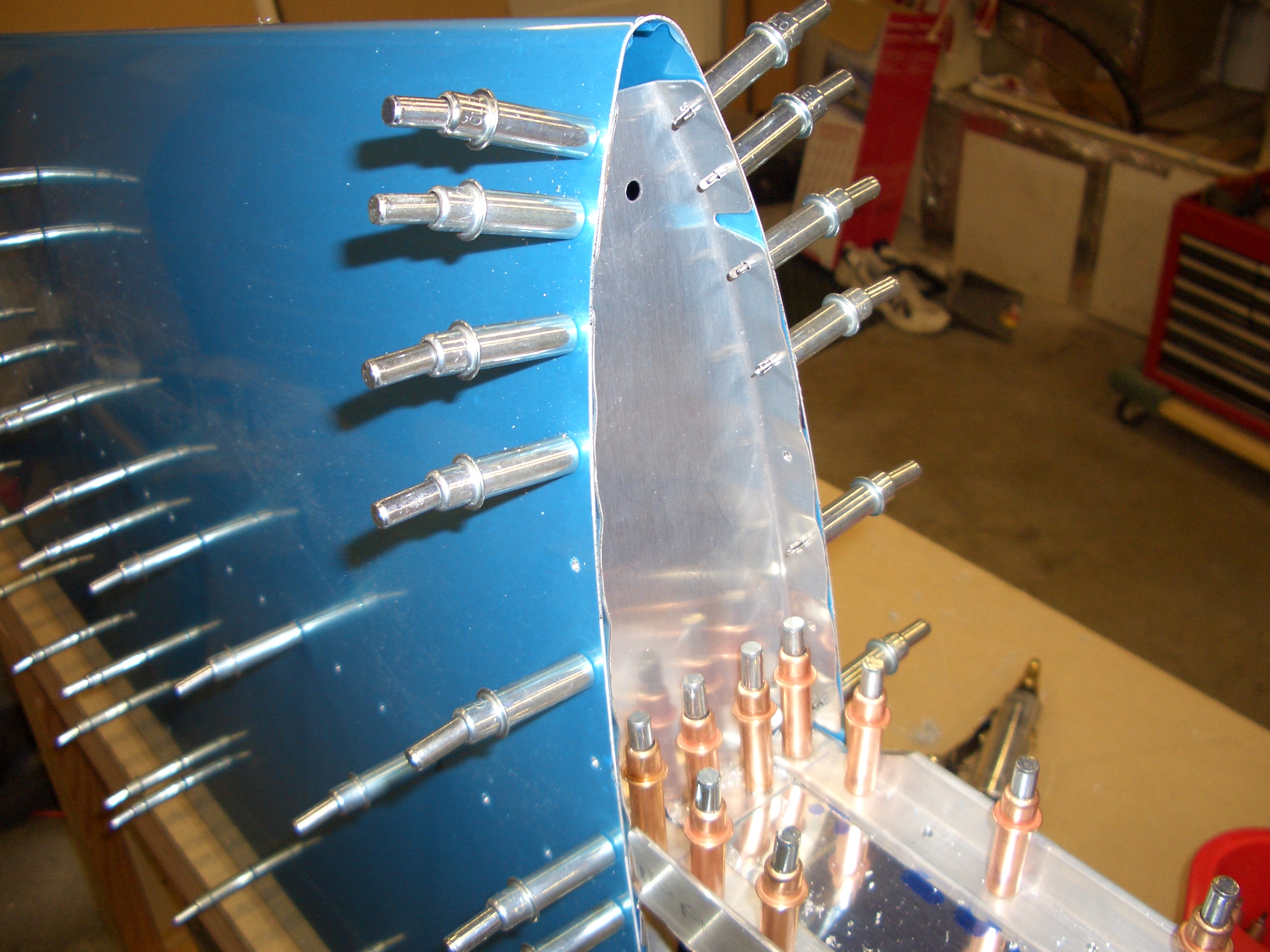
Here are the two HS-405 ribs drilled to the skin (the ribs in the center with the lightening holes).
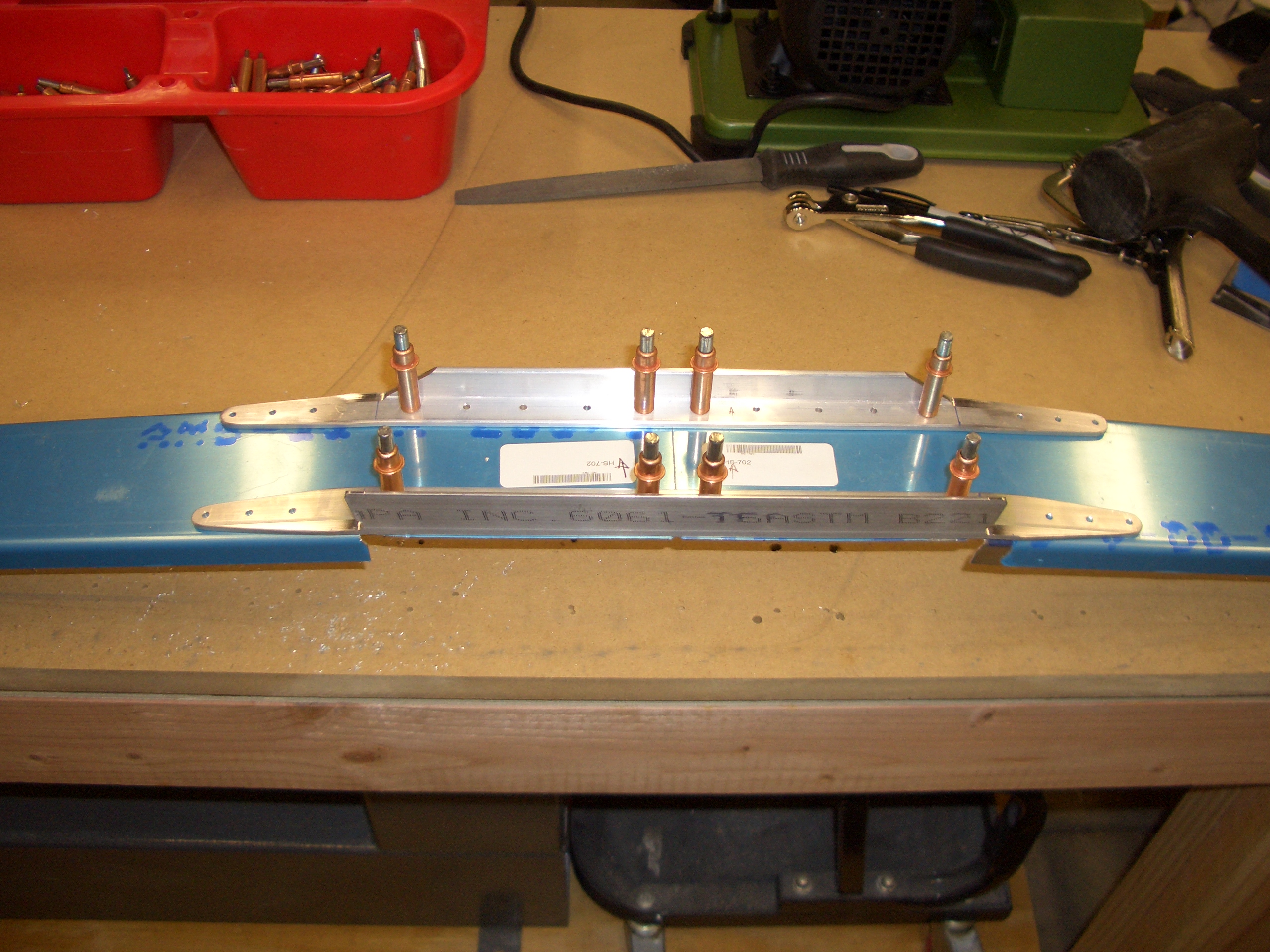
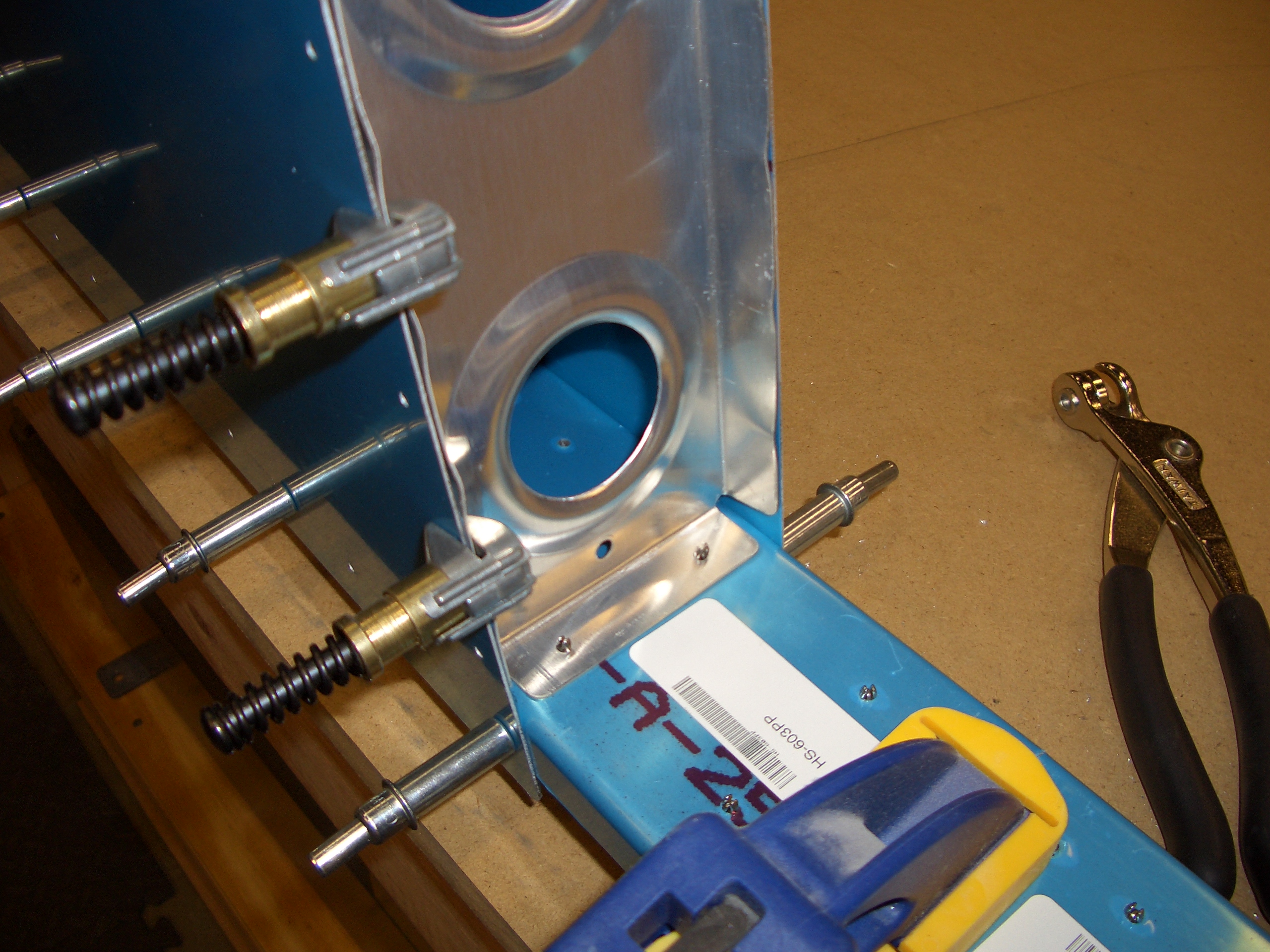
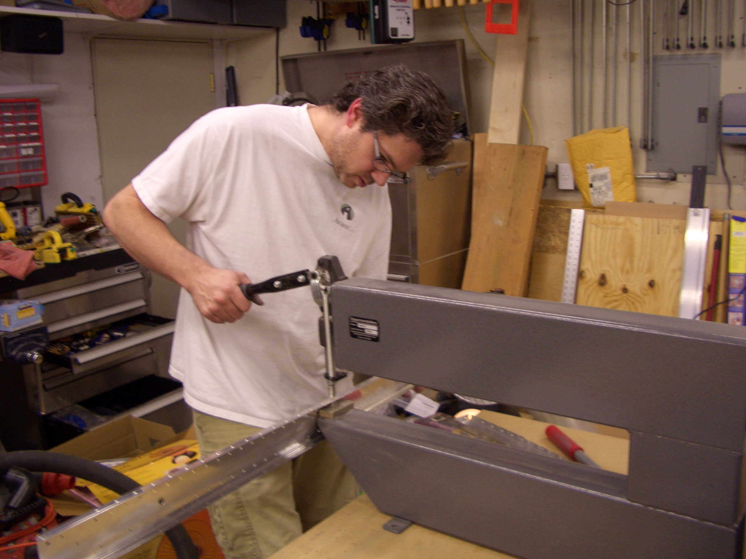
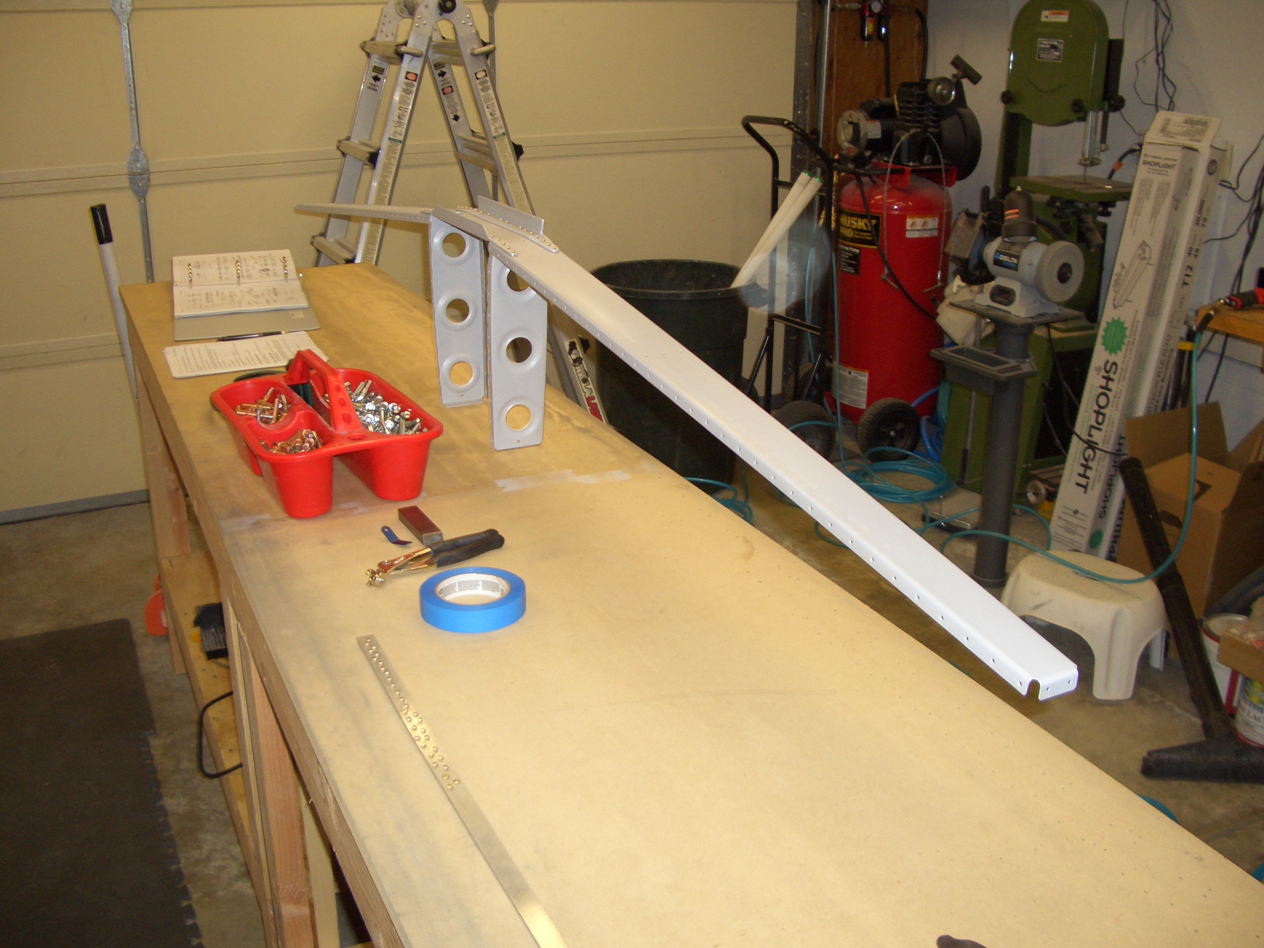
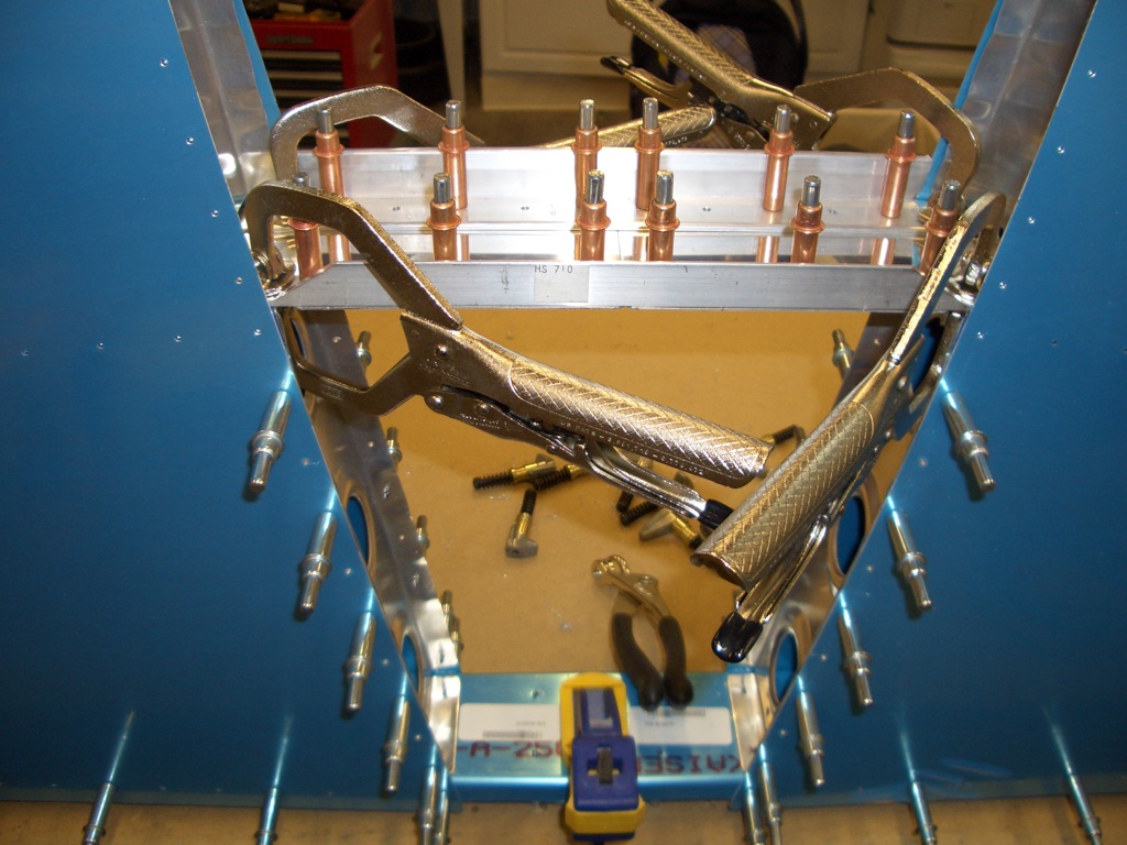
If you haven’t seen these LockJaw vise clamps, you should really check them out. Instead of the typical vice grips that have an adjusting screw that adjusts the jaw separation when closed, these have an adjusting screw that adjusts the clamping pressure. Once you set the clamping pressure you want, you can clamp material of various thicknesses with no further adjustment. I really dig it when somebody creates a clever tool like this.
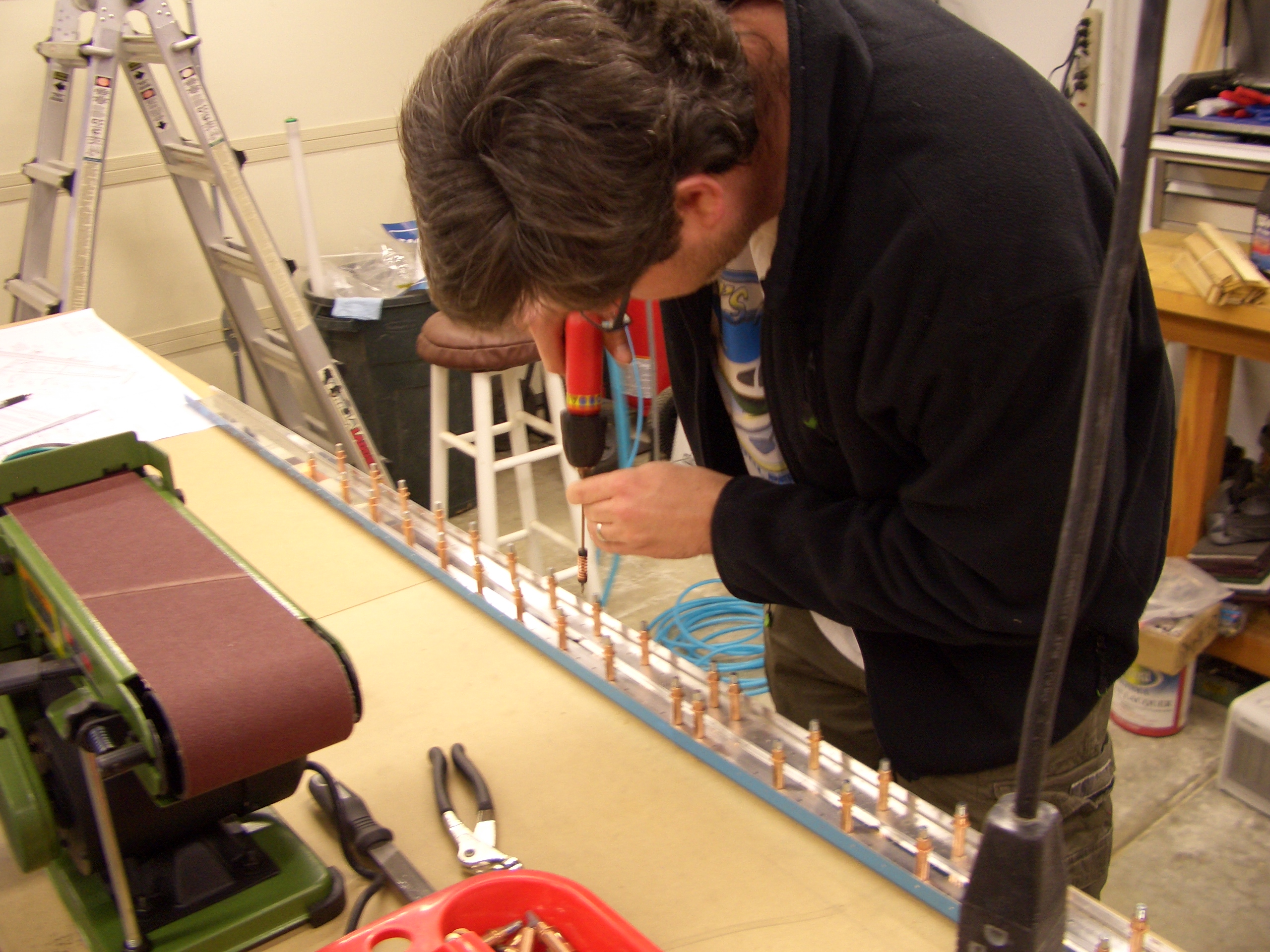
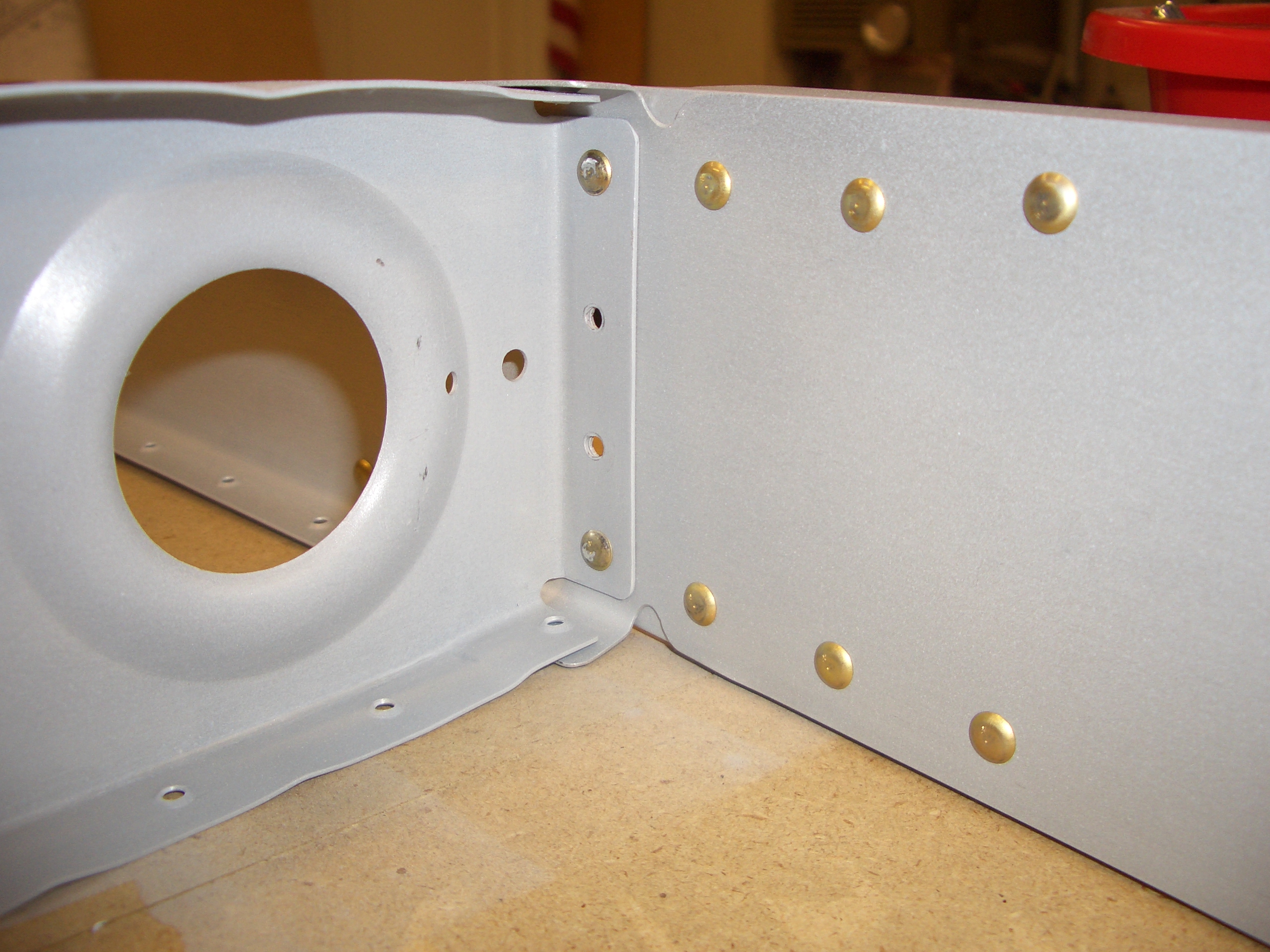
Here is the HS-404 nose rib drilled to the skin. Getting this matched drilled to HS-405 was kind of a bitch. Van’s recommends using an angle drill, but because of the tight fit, I couldn’t get it remotely perpendicular to the front flange of HS-405. I ended up using a 12″ #30 drill bit from below and flexed the drill bit enough to get perpendicular to the flange.

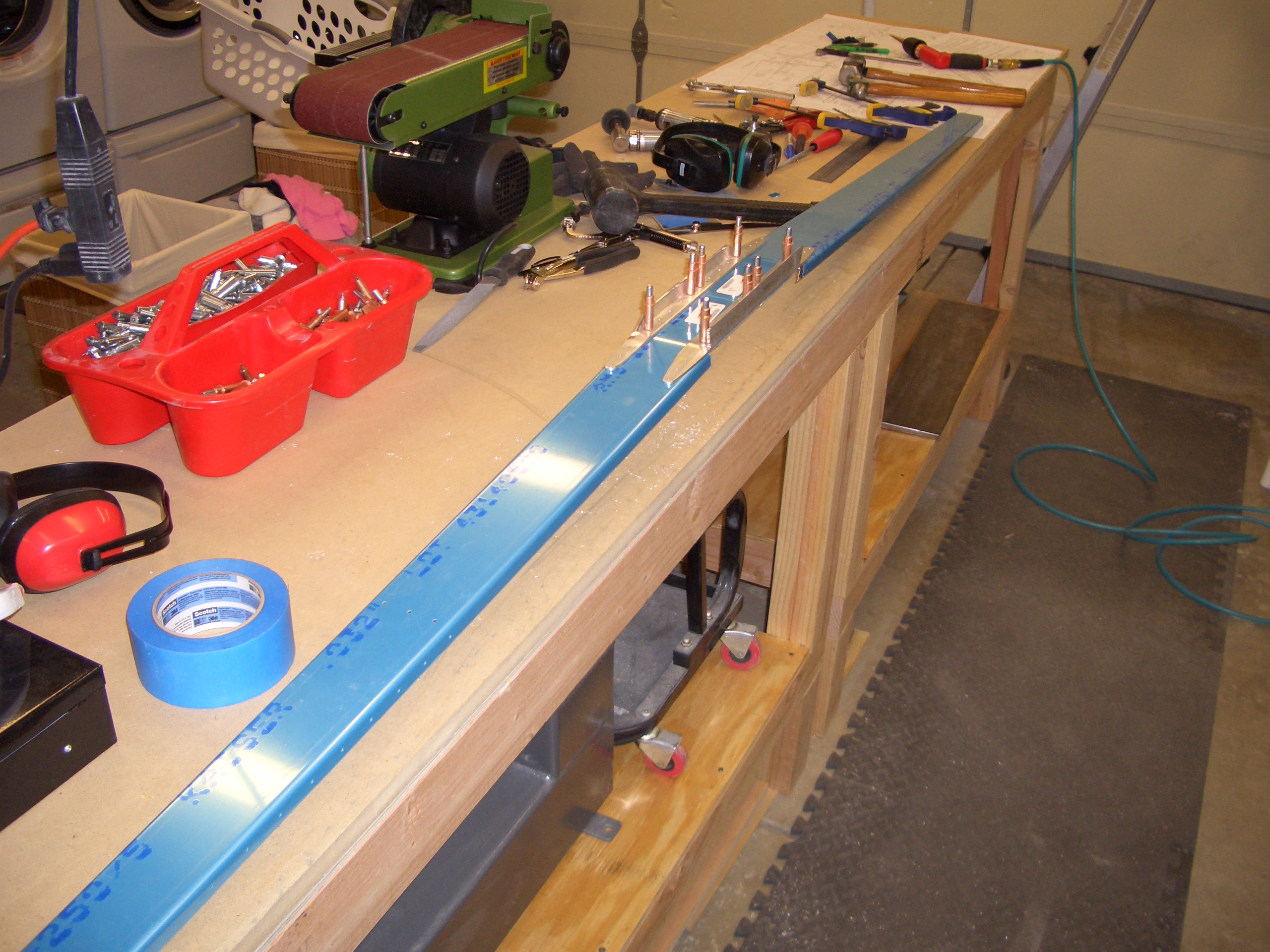
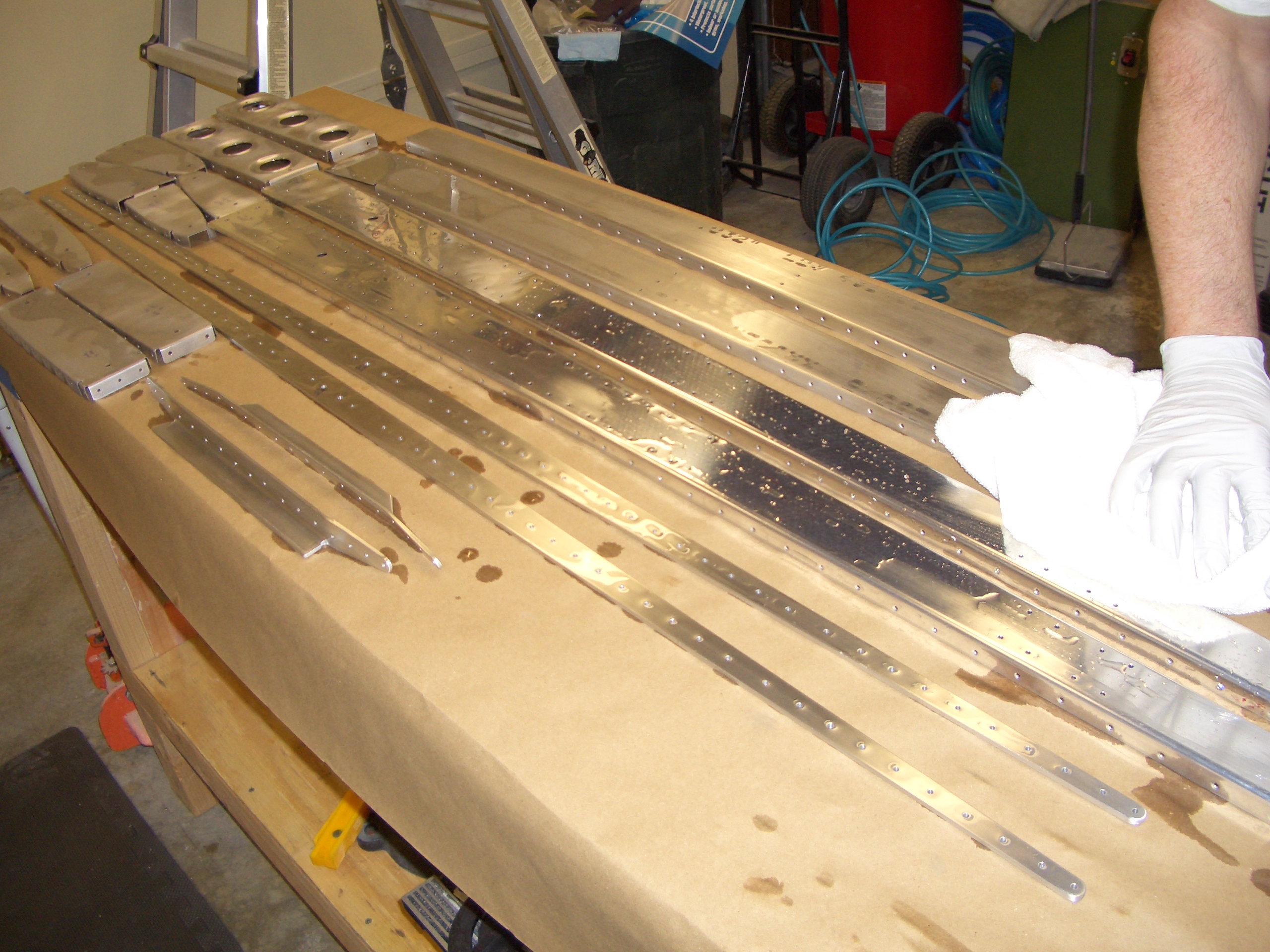
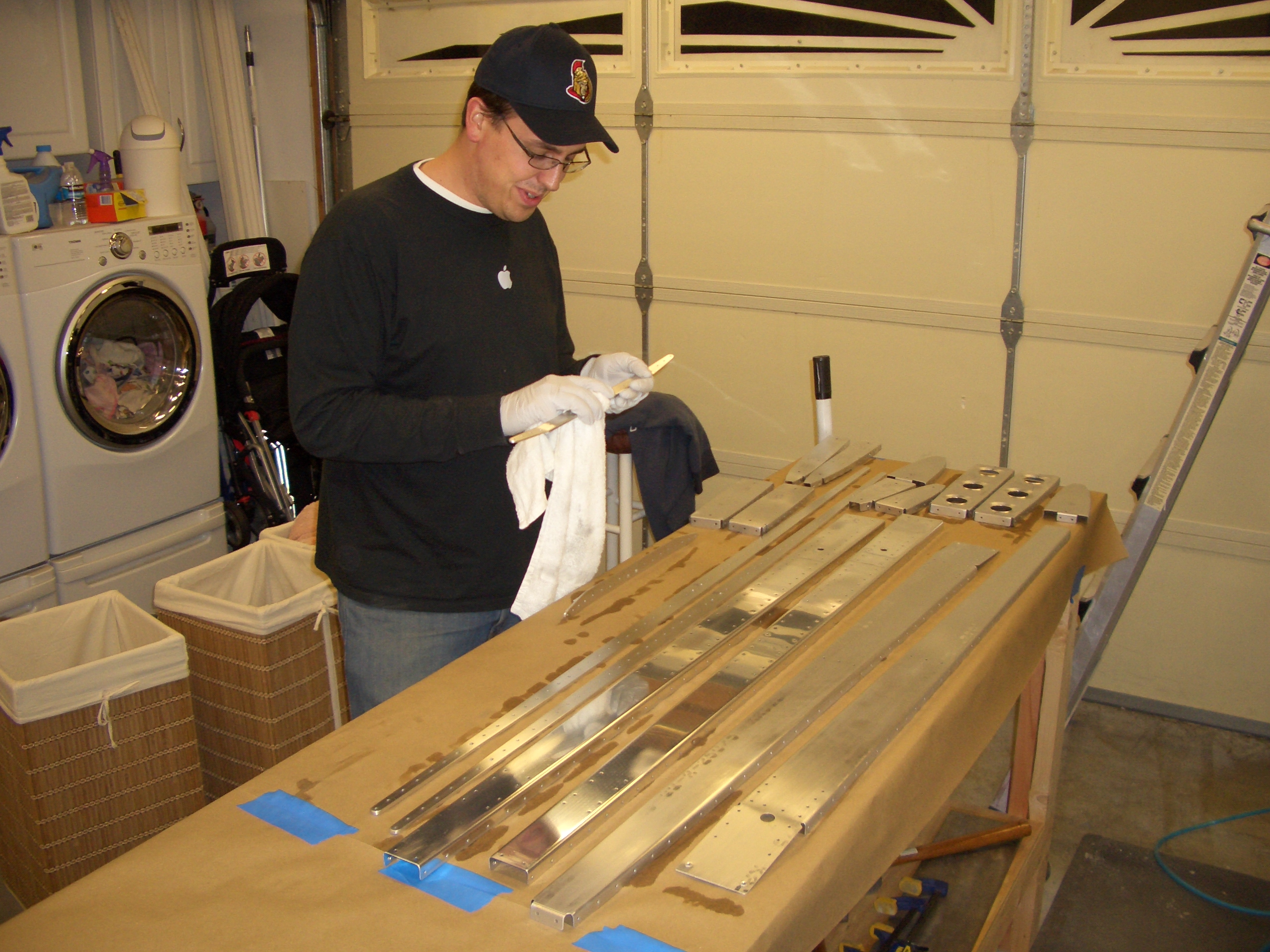
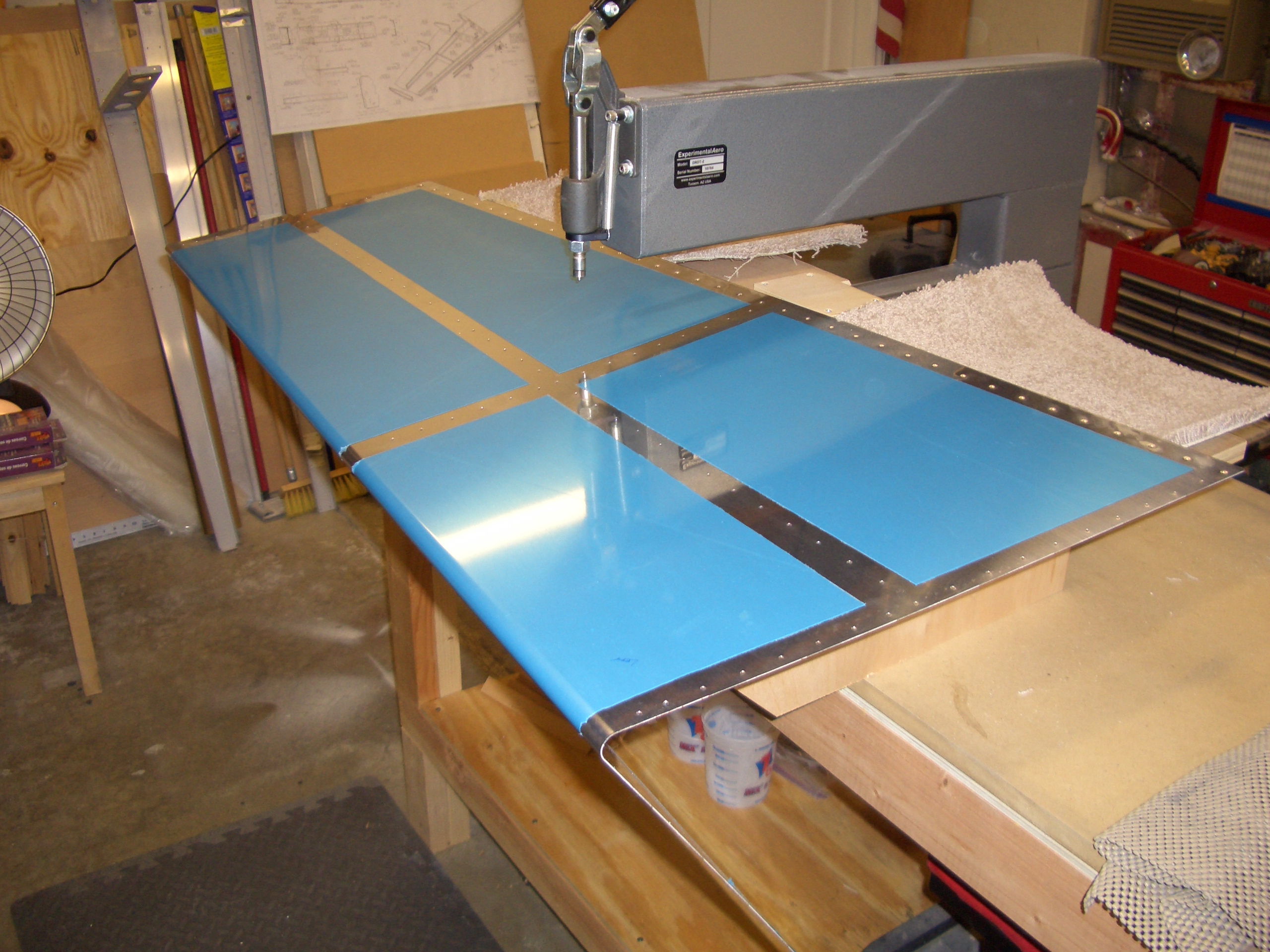
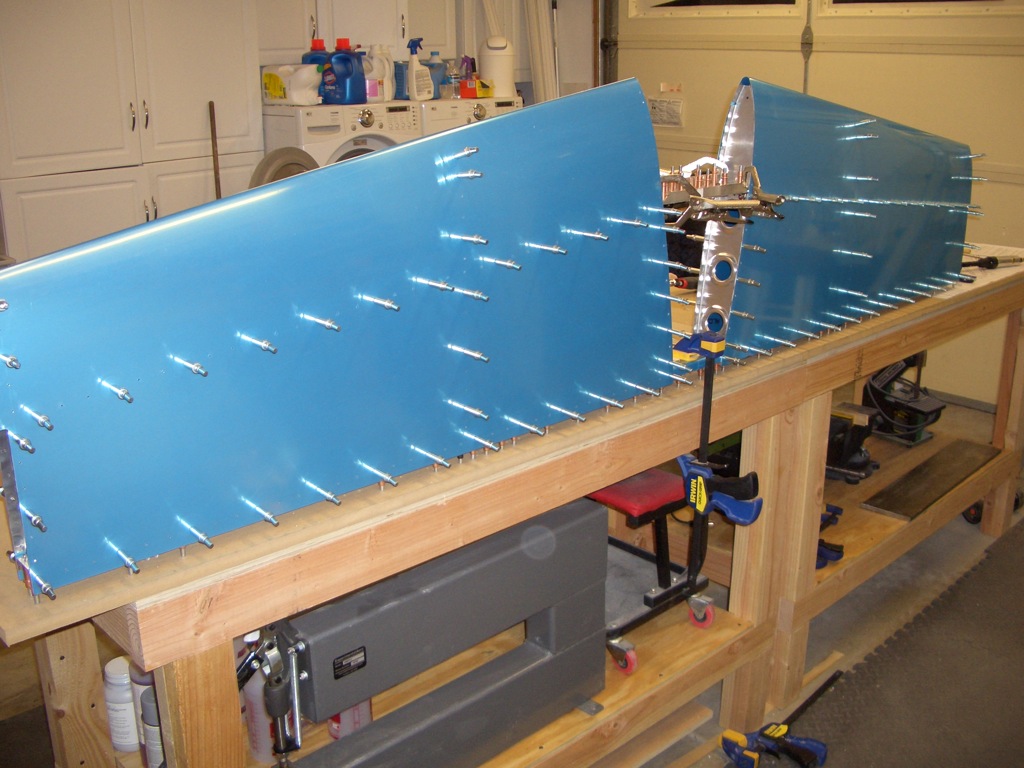
This looks a lot like the picture above, but here, the skins have all been match drilled to the internal structure. The skins are ready to come off and get deburred and dimpled, but I’m beat. I built these benches a couple of inches taller than the plans since I’m 6′ 4″, but I now wish I had gone up a few more inches. I spent a lot of the night hunched over and my back is killing me.