Upgraded to SkyView HDX Displays

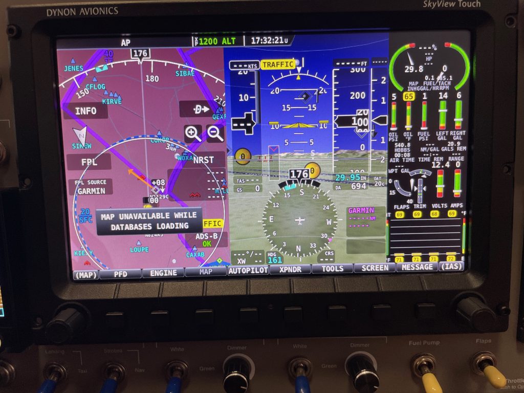
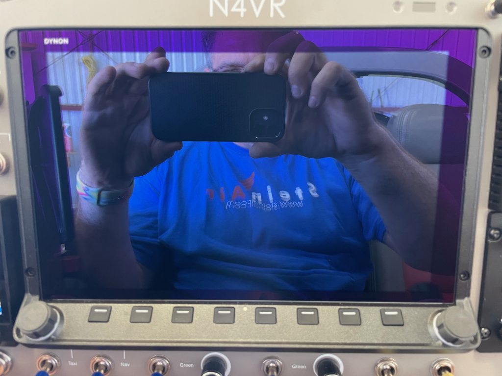
I’ve been planning on updating from my SkyView Touch displays to the SkyView HDX displays for quite awhile, but was holding off until Dynon offered a trade-in plan. They recently did that, but the trade-in offer was disappointing, so I decided to just buy the new displays and will sell these. Here’s the old pilot side display.

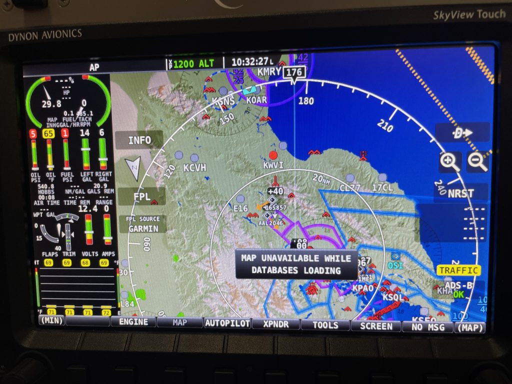
And here’s the old co-pilot’s side display. These displays have worked perfectly and will be a great addition to some other builder’s plane.

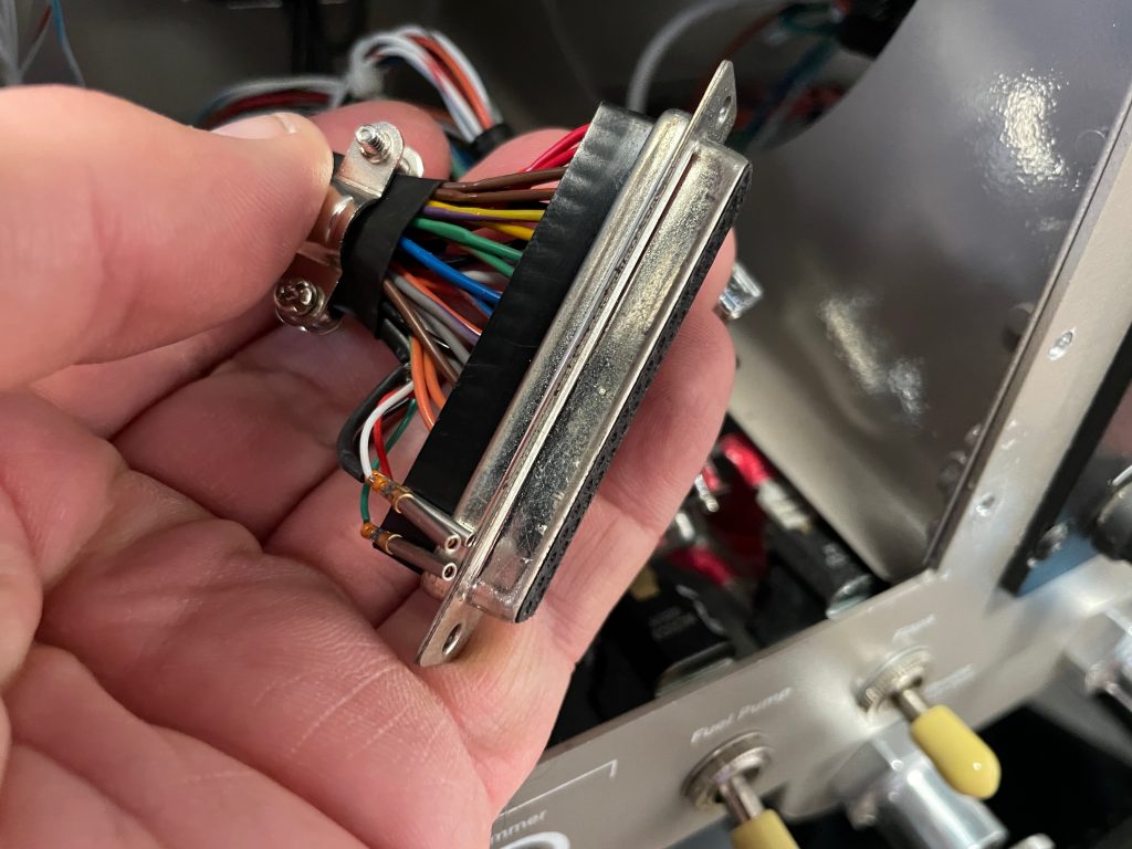
For some reason, Dynon no longer supports the USB pins in the DB-37 connector. I was using these for the panel mounted USB ports so that both of the USB ports on the rear of the SkyView were available. I replaced the panel mounted USB ports with ones that just plug into the back of the SkyView displays. With those and the WiFi dongles, both USB ports are now used on each display. The only concern I have with this is that I have considered adding the video dongle so that I can add a camera feed, but perhaps I can use a USB hub if I do that.

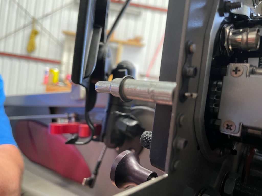
The new HDX displays only use two screws per side instead of three. The upper one is fortunately in the same location, but the lower screw doesn’t line up with the existing nut plate, so I needed to install new nut plates above them.

Here’s one of the new displays installed. These displays don’t completely fill the hole in the panel, so there’s a cover plate hidden behind the lower lip of the display to cover the rest of the hole. You can see in the upper right where the panel mount USB port goes. It’s removed because the new ports with USB connectors on the other end are on order and should be here soon.

You can also see that the lower lip of the display obscures part of the panel labels. It’s not too bad from where I sit, but it would have been nice if this wasn’t an issue.

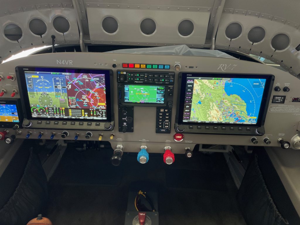
Here are both displays installed and configured. They’re somewhat brighter than the old displays and support a horizontal engine strip (as shown on the left display) as well as better touch based menus and screens.

Added Heated Pitot Tube

I had my pitot tube freeze up at 15,000′ last summer in IMC. The Dynon algorithm doesn’t handle this situation very well; it’s supposed to fall back to GPS ground speed in the attitude calculation if the pitot indication is lost, but that apparently only works if the airspeed actually goes to zero. If the pitot tube is only partially frozen over and the airspeed is fluctuating, the indicated pitch attitude of the aircraft will swing widely and the autopilot will try to follow it. That’s frankly dangerous and Dynon should address this.

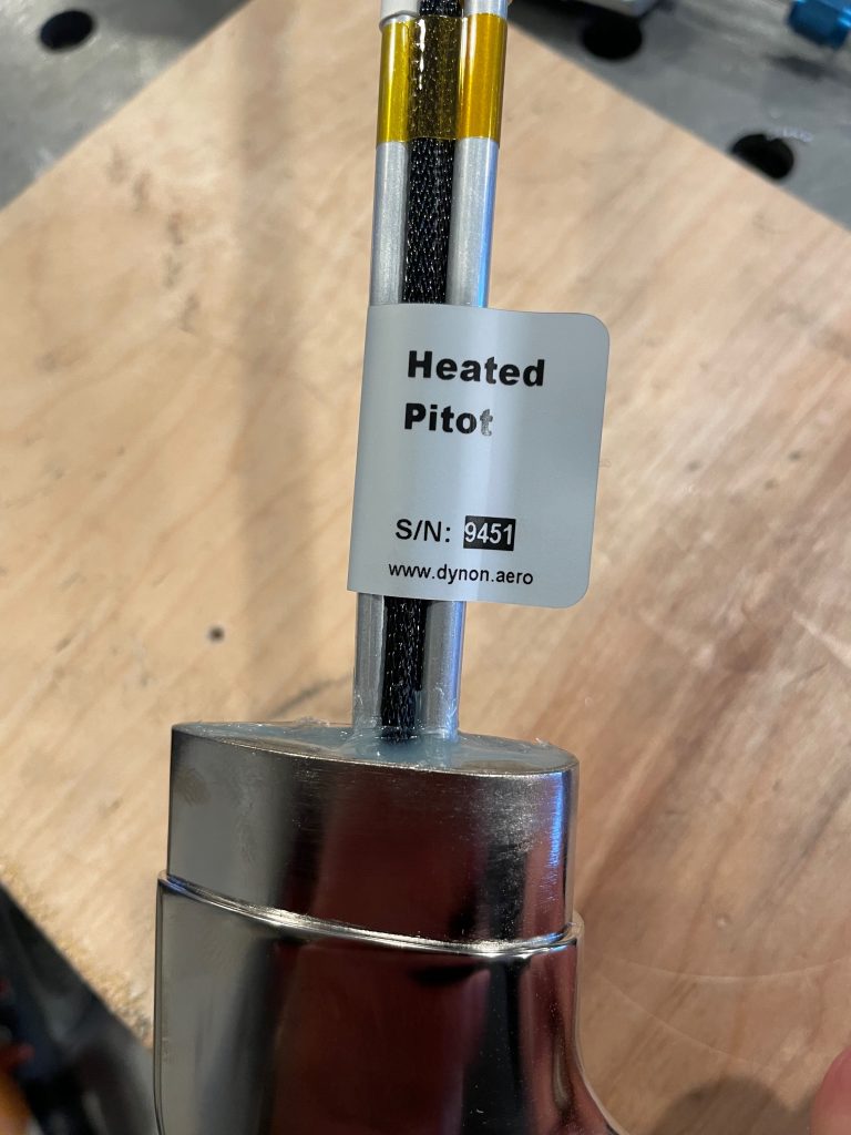
To reduce the likelyhood of this happening, I ordered a heated pitot tube and finally took the opportunity today to install it.

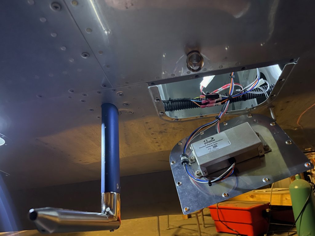
The heated pitot tube requires the installation of a heated pitot controller near the pitot tube. If I were installing this during the initial build, I would have mounted this to a nearby rib, but that was going to be rather challenging in a completed wing, so I decided to install it to the adjacent access plate. I drilled four mounting holes and dimpled them so that the screws sit flush. With the plate installed, none of the wires can rub on the controller or access plate nut plates.

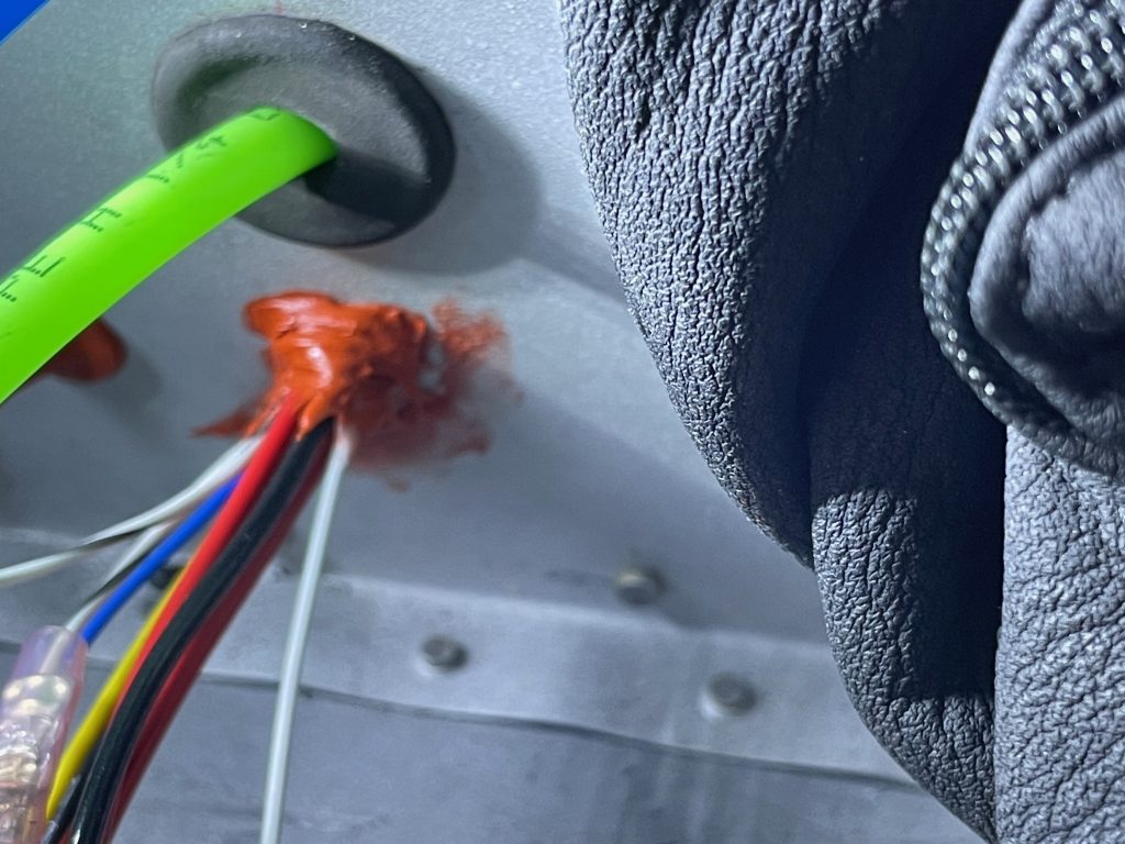
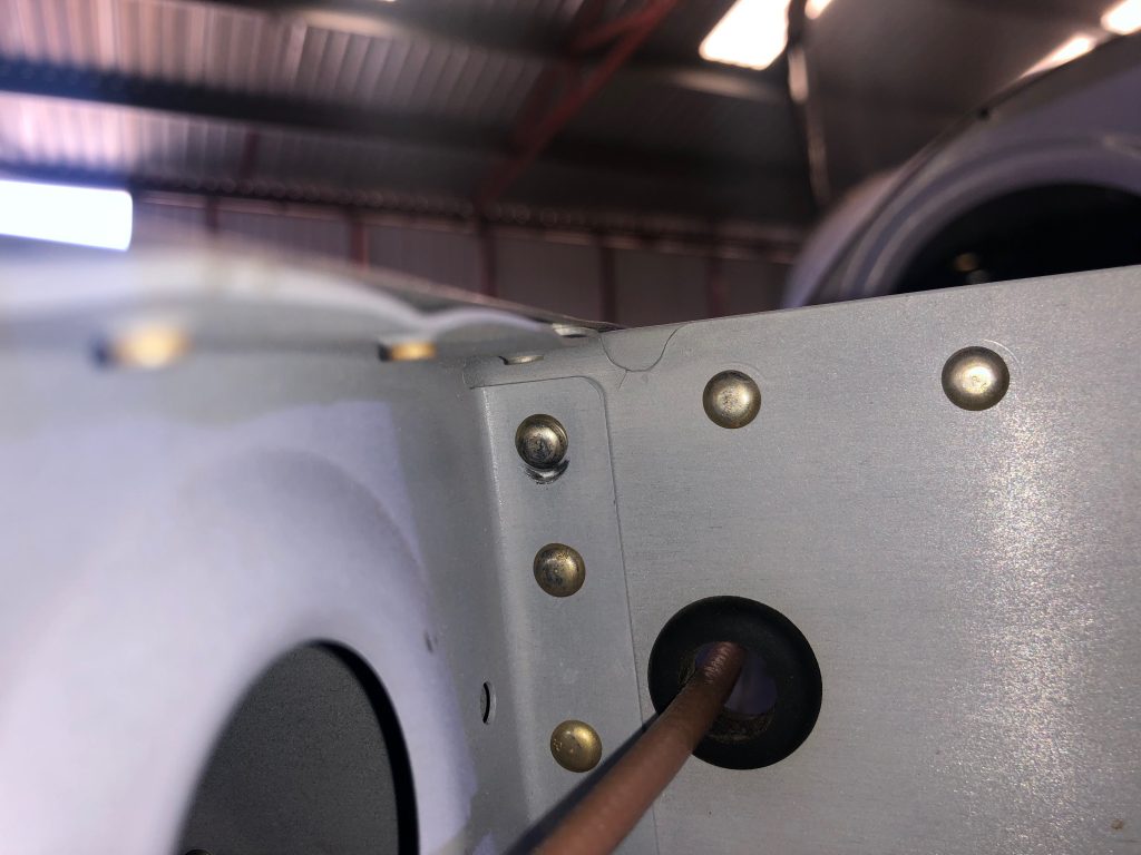
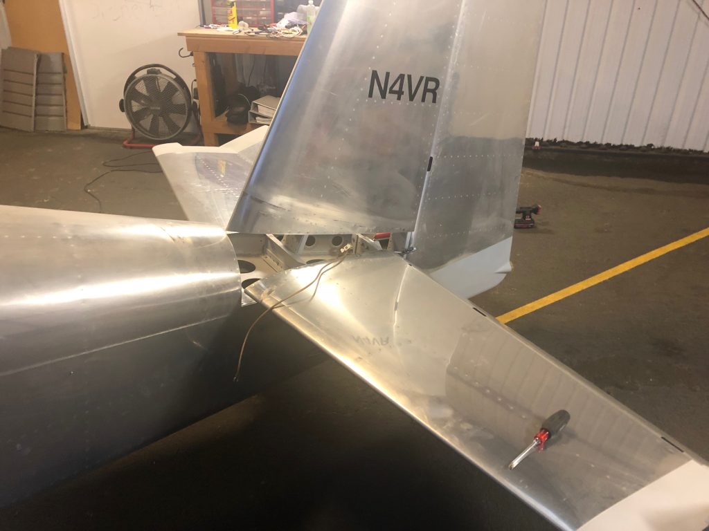
I had to fish three additional wires out to the controller (power, ground, and sense wire to be routed to the EMS). Unfortunately, I ran the wing wires through a snap bushing in the fuselage and then into the wing conduit between the wing and fuselage. The additional wires wouldn’t fit through the snap bushing, so I had to cut it out and then use some RTV to prevent the wires from chafing on the edge of the hole. If I were building again, I would have drilled a larger hole in the side of the fuselage and left the wing conduit long so that it penetrated into the fuselage. It would have made running these additional wires substantially easier. The sense wire is not currently connected to the EMS as accessing it is quite difficult. I’m planning on adding the forward fuselage access panels at some point and will hook up the sense wire when I do that.

Replaced Tailwheel

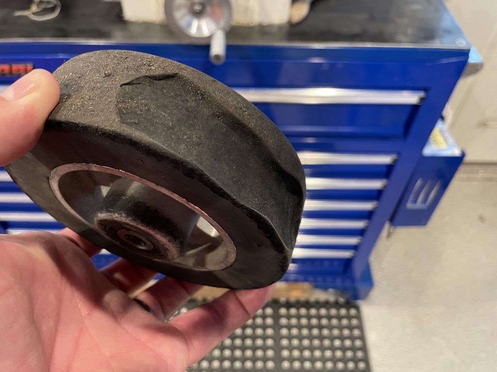
On one of my fuel stops on my recent trip back to TX and OK, I felt a weird vibration on landing, and it turned out that a chunk of the rubber from the tailwheel had broken loose. There had always been a defect in the rubber from the time the tailwheel was new, but I thought it was cosmetic. It lasted over 8 years and nearly 500 hours of flight time though, so I can’t complain too much.

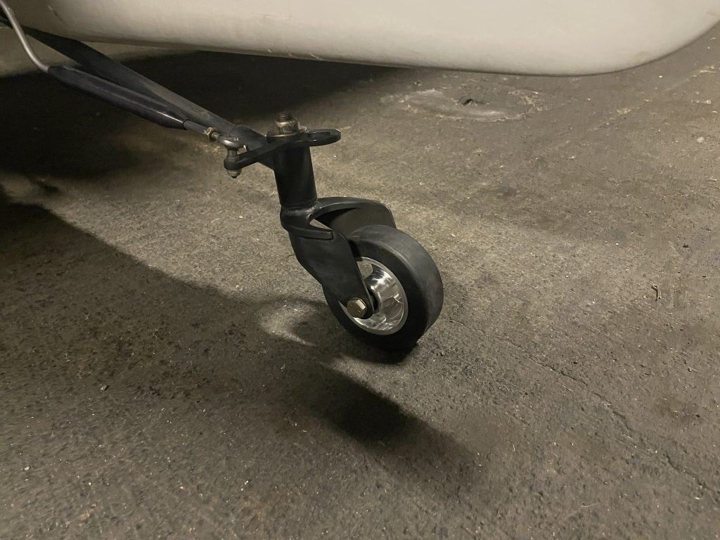
In the meantime though, FlyBoy Accessories started selling this 4″ lightweight tire that is 13.5oz lighter than the 5.5″ tire above. That moves my CG an additional 0.13″ forward which should further help with the aft CG issue I’ve always had.

Replaced Pitch Servo Shear Screw

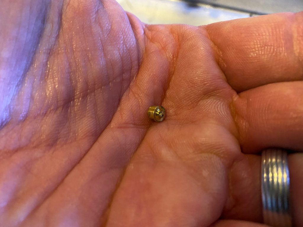
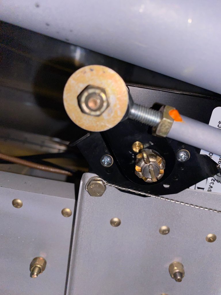
Sometime in the last couple of weeks, I noticed that the pitch servo wasn’t controlling the plane. I did some ground diagnosis and determined that the shear screw had sheared or some reason. I don’t recall any forces that would have caused this, so I can’t say why it happened. Dynon sent out a shear screw replacement kit a few days ago and I stopped by the airport this morning to install it and put the plane back together.

It’s amazing that this tiny cross section of brass is critical to the autopilot being able to control the aircraft.

I reassembled the control arm and tested the autopilot servo. Everything worked as expected, so I reinstalled the interior and updated the logbook.

Swapped Propellers

The RV-7 was designed before the days of composite constant-speed propellers, and was further designed for the 200hp, angle-valve IO-360 motor. Taking Van’s advice to build the lightest plane possible, I opted for the WhirlWind Aviation 200RV composite prop and the much lighter IO-375 motor. This meant I was approximately 70lbs lighter in the nose than the plane was designed for. This put my C.G. much farther aft than typical, and it was in fact easy to load the plane aft of the aft C.G. limit.

I spoke with Van for a bit at a party last year, and he indicated that the easiest change to make (short of just bolting on some weight) would be to switch to an aluminum constant speed propeller. When my 200RV prop started slinging grease back in the spring, it seemed like the perfect time to do the swap.

I ordered the Hartzell C2YR-1BFP/F7497 through Van’s. This is a 74″ prop and not normally recommended for the RV-7 due to being 2″ longer than the 72″, recommended prop. However, I spoke with someone at Hartzell, and he indicated that there were advantages in thrust with the 74″, and the extra weight only helped my situation. The only downside for me is reduced ground clearance. The 200RV had 8 3/8″ under normal gear compression in a level attitude, so this prop should have 1″ less, or 7 3/8″. In a hard landing, or if I inadvertently raised the tail too far, this would be reduced. However, I virtually always fly off hard surface runways and generally do tail-low wheel landings, so I’m not particularly worried about the reduced clearance.

The prop shipped 4-6 weeks later and pretty quickly landed at the UPS hub in San Jose, CA where I live. Unfortunately, UPS then lost track of it for three weeks! Eventually, it turned up in a trailer full of packages that apparently sat unopened that whole time. I dropped by their hub and picked it up and brought it to the hangar where I opened it and got it ready to mount on the plane.
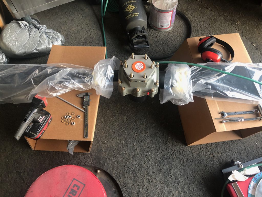
The first step is fitting the rear spinner bulkhead. This needs to be cut to match the doubler and then relieved further to fit on the propeller without touching the hub itself.
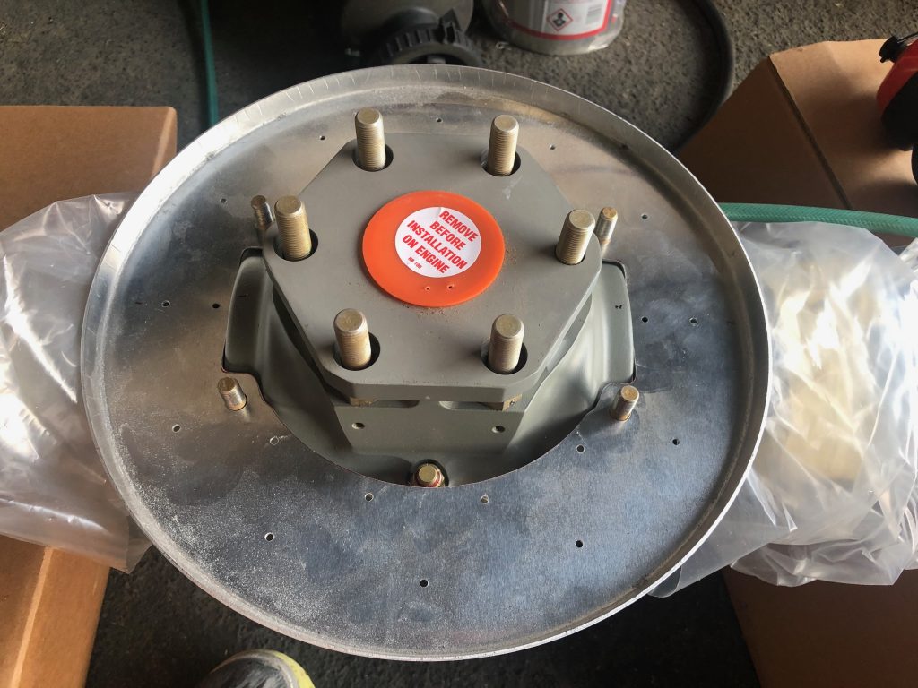
My buddy Michael was kind enough to let me drop by his place and shoot some of the Stewart Systems primer on the front and rear bulkheads, then I riveted the two parts of the rear bulkhead together.
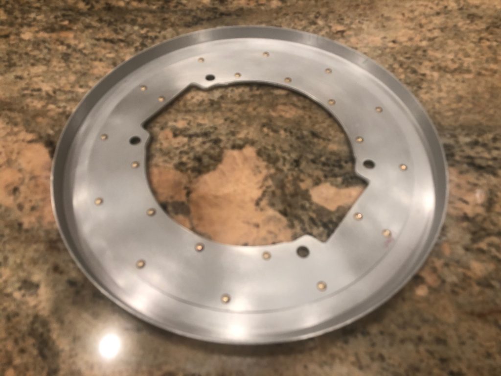
When everything was ready with the new prop, I pulled the old prop from the plane.
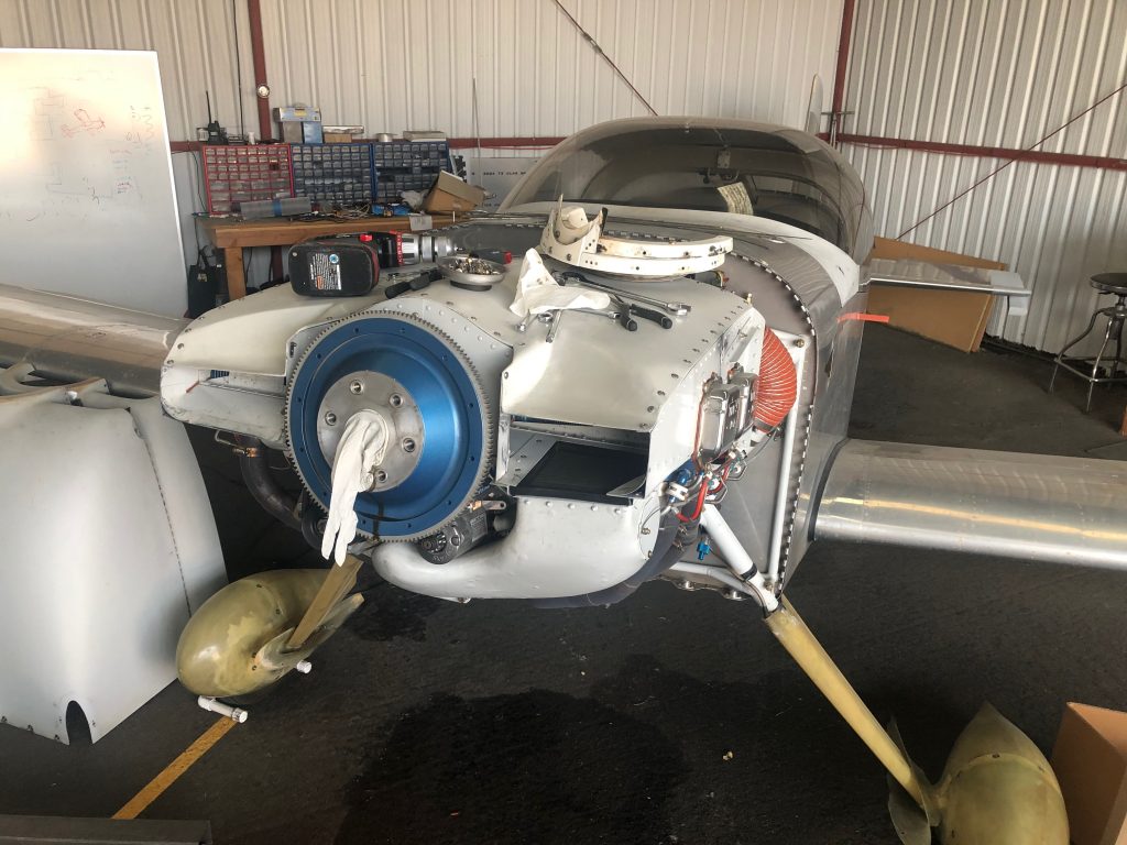
I’ve had some back pain recently, so I used this lifting sling with my shop crane to get the old prop off and install the new prop on the plane. This was far easier that trying to hold the prop with one arm while manipulating the bolts with my other hand.
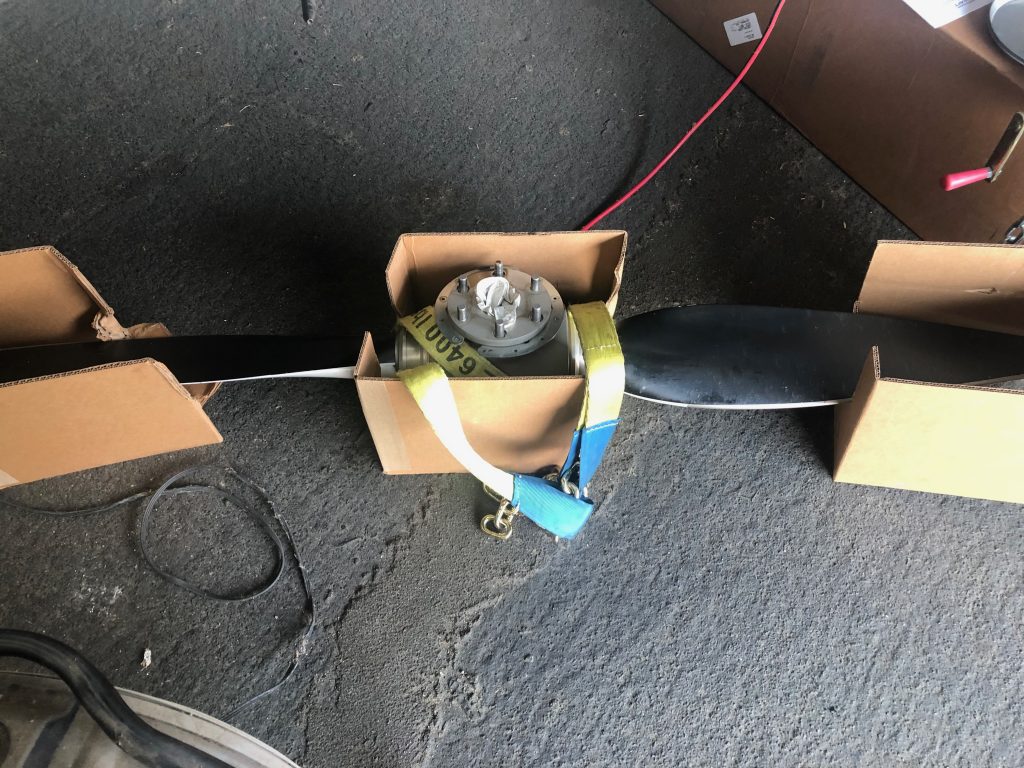
I taped the new bulkhead to the flywheel while installing and safety wiring the new propeller.
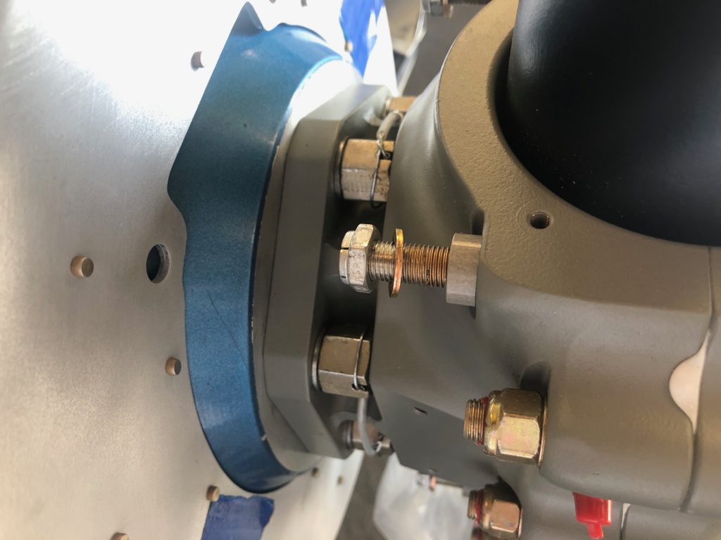
I then installed the rear bullhead to the hub retaining bolts and torqued them to spec.
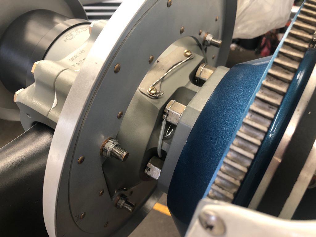
I temporarily installed the front bulkhead so that I could begin fitting the spinner.
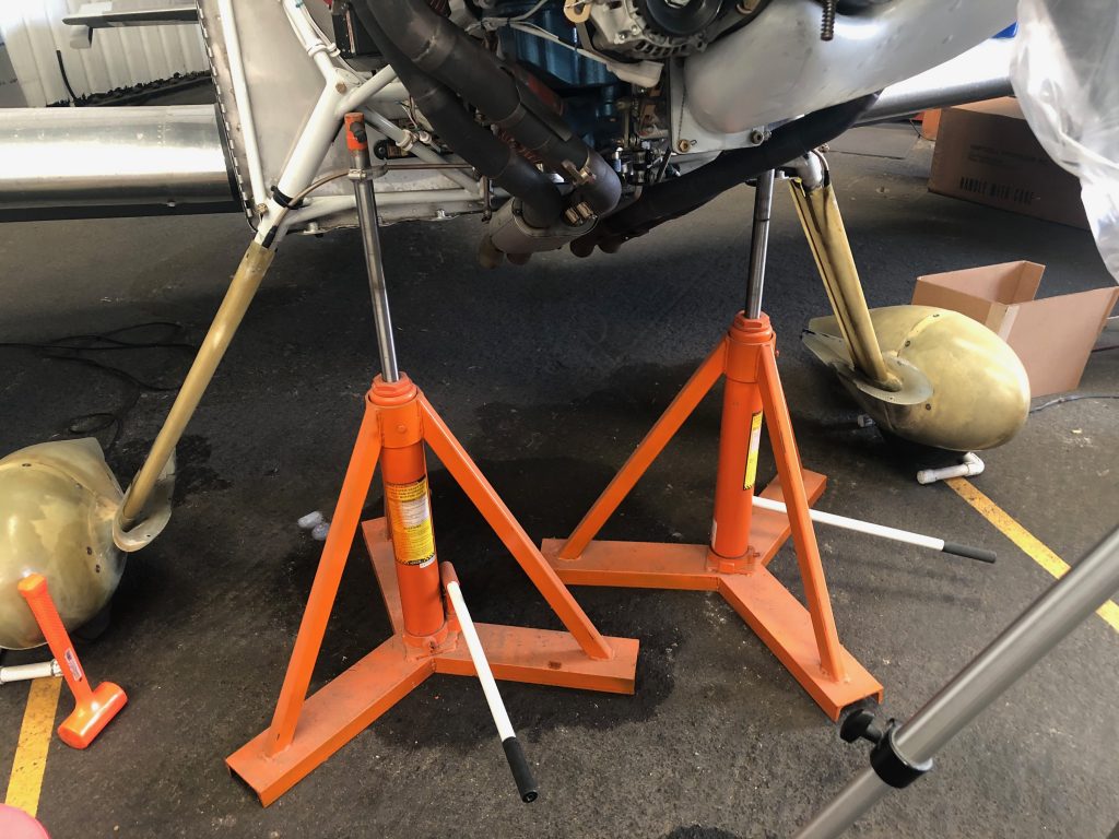
I needed to be able to turn the engine freely when fitting the propeller, but I needed it to be fairly stable. I used the same technique I did when fitting the wheel pants, and jacked the plane up by the engine mount. I then removed the lower spark plugs so that the engine could spin freely.
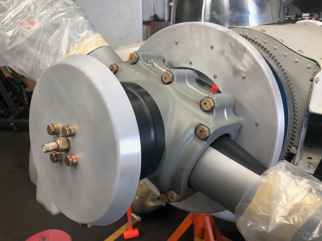
When fitting the spinner, I also needed to be able to cycle the blade from the fine pitch stop to the coarse pitch stop. I ended up using some padding and one of my Bessey clamps which worked perfectly. Here is the propeller at the fine pitch stop.
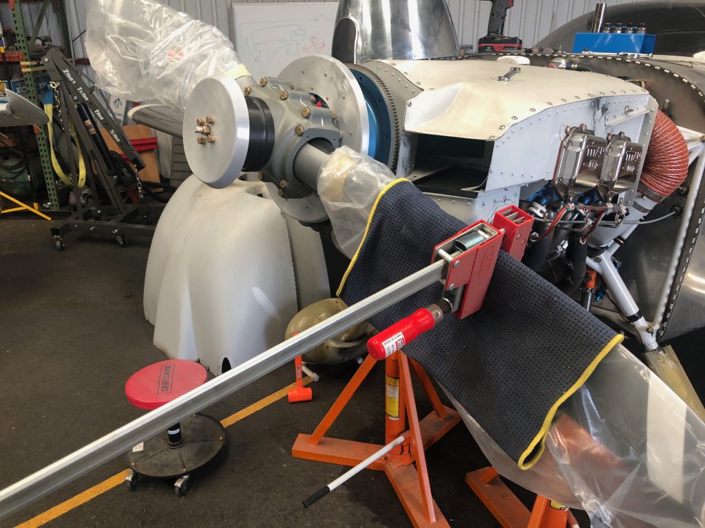
By just pushing down on the clamp (and holding the propeller tip to prevent it from rotating the engine), it was easy to twist the blade to the coarse pitch stop.
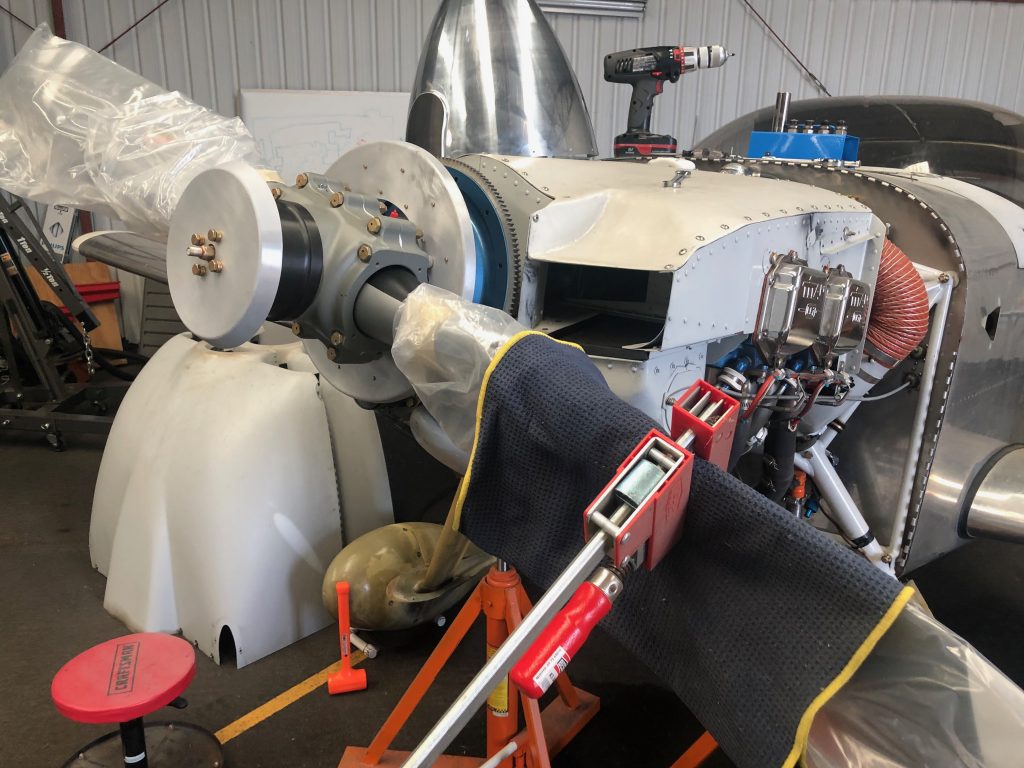
I’m using the Cummins Spinners spinner for this propeller. I emailed Alan back in the spring to inquire about purchasing one of these, but there was no response. Others online said that hadn’t been able to get ahold of him for over a year and a half! I gave up hope and ordered the spinner kit from Van’s, but just before install, I received an email out of the blue from Alan saying he had a spinner ready to ship! It took a couple of weeks to get here from Australia, but it’s worth it for the look of a polished spinner on the plane.

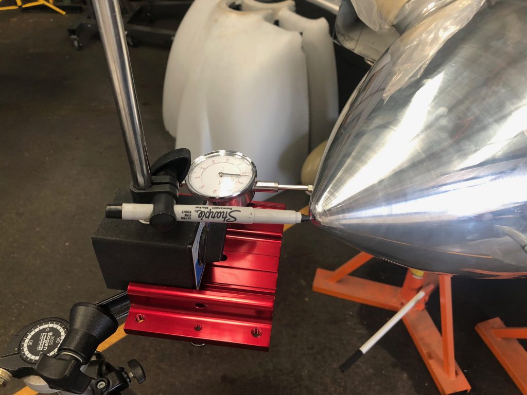
To ensure the spinner was centered, I used a combination of a marker at the tip and a dial indicator on the side to measure wobble. I think it’s impossible to get this to 0″, but I feel like I got pretty close. You couldn’t see any deviation with the marker tip and the dial indicator showed +/- 0.003″ deviation. Since the spinner is 0.065″ aluminum, that’s only about 5% of the thickness of the spinner!
After drilling all of the holes, I set the nut plates on the front bulkhead.
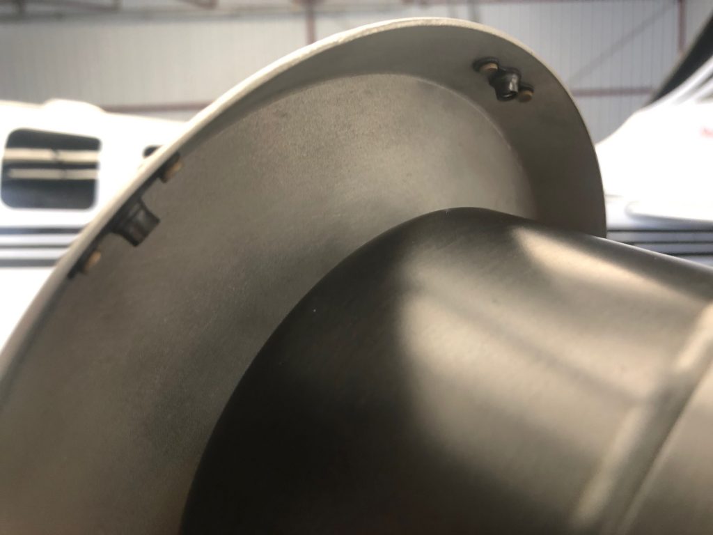
…then safety wired it in place.
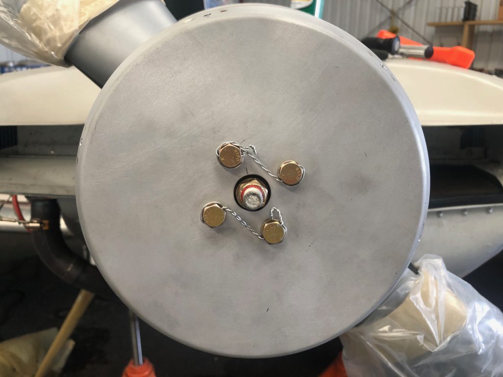
My buddy Greg found a metal polishing place about 45 minutes from my house, so I dropped the spinner off and had them polish it to a mirror finish.
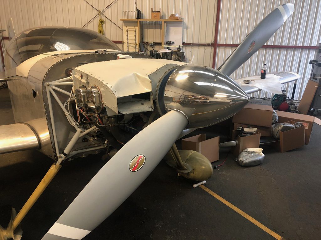
Interestingly, the prop clocks at a different location when the engine’s stopped. The old prop would be level after shutdown.
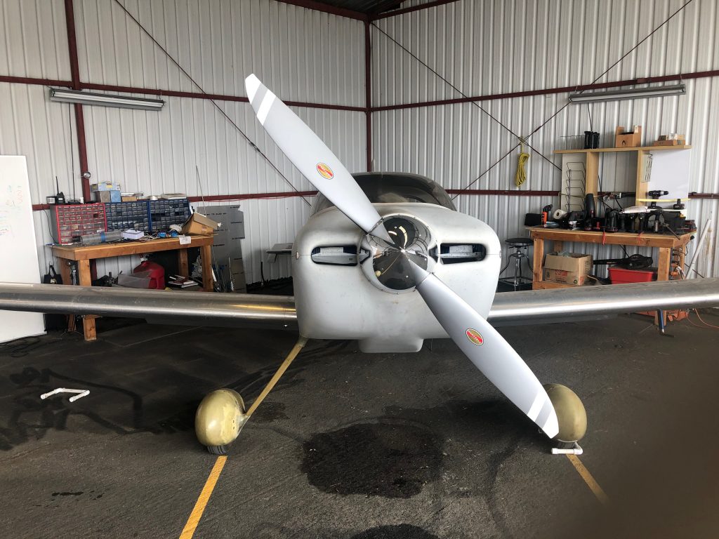
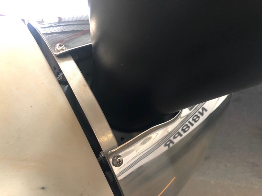
It looks like I’m going to need to raise the prop a small amount due to engine mount sag. You can see the misalignment of the spinner and cowling clearly here. The spinner sure does look sharp though.
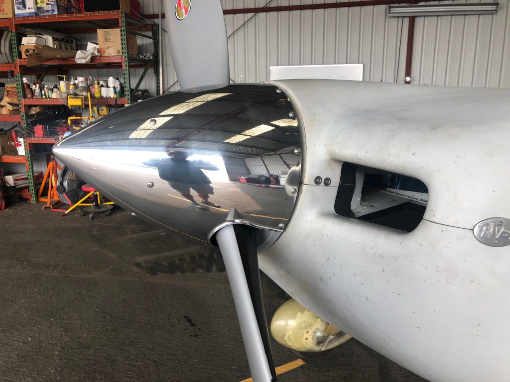
I also need to fabricate filler pieces to fit behind the blades, but that can happen down the road a bit.
Replaced Fuel Flow Sensor

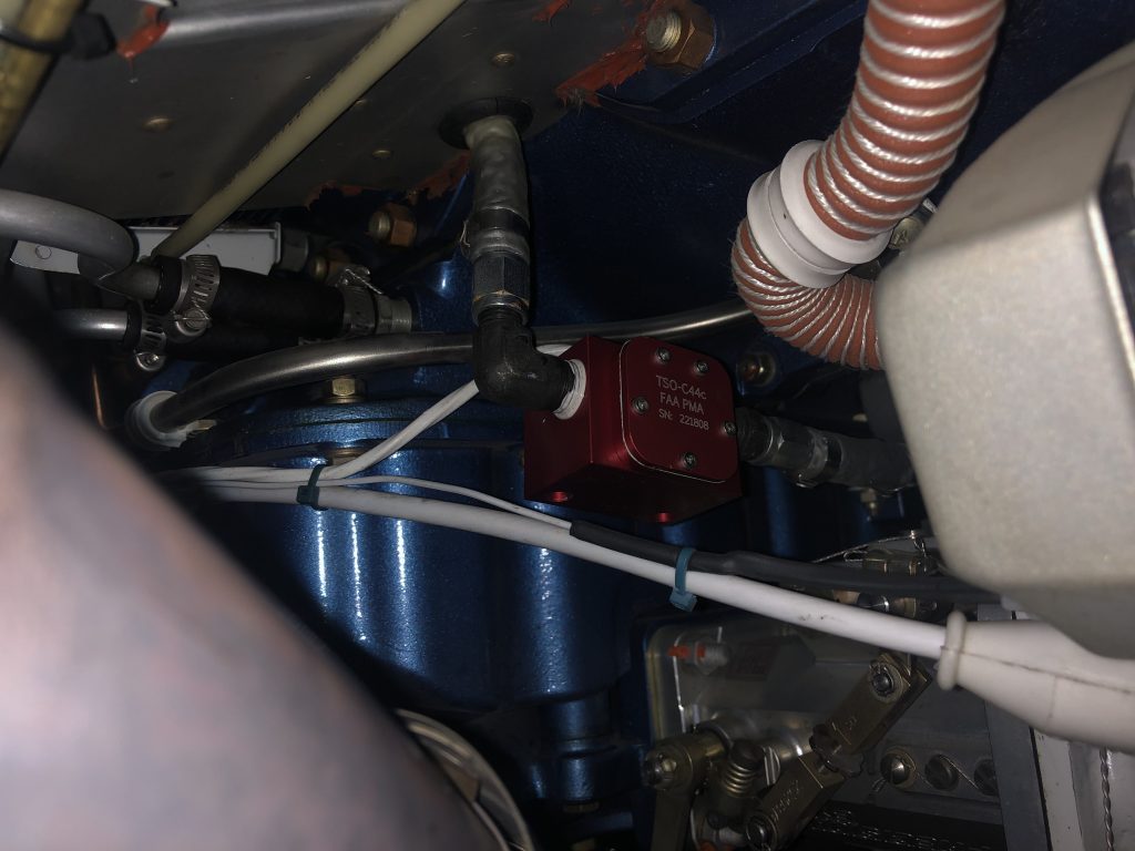
My fuel flow has been erratic again recently. This has happened a number of times and Electronics International has always indicated that the cause is almost always the electrical connections. I’ve tried crimp connectors, solder, solder sleeves, and finally their own OLC-1 and now OLC-2 connectors. Interestingly, the problem would always appear to be resolved for a bit, but would then reappear some number of hours later.

A friend mentioned that he’d had a similar experience and a replacement fuel flow sensor fixed it. Out of other options to try, I ordered one and installed it tonight.

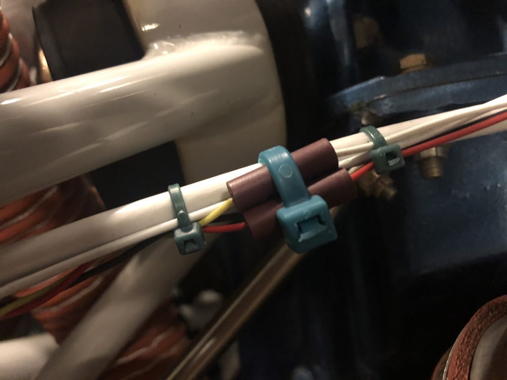
Their new OLC-2 connectors have two crimp screws per connector so you don’t have to try to hold both wires in place simultaneously while trying to tighten the screws. I don’t like how these connectors provide no strain relief for the wires, so I did my best to immobilize everything.

I leak tested everything and ground-ran the engine. Initial run showed nice, solid fuel flows.

Oshkosh 2019!

My daughter Madeline and I had been planning for months to go to Oshkosh together this year. We even took the time to make a couple of custom shirts to wear while there.She and I took off the Friday before Oshkosh for an overnight stop in Salt Lake City to visit some family. It was a little bumpy, and her stomach started hurting on the flight there. We decided to stop at Wendover, Utah to rest and see how she felt. After about an hour there, she felt like she just couldn’t make the rest of the flight. We talked about having my wife fly out to Salt Lake City and bring her back commercially, but I decided the easiest thing to do was just fly back to CA. Since she knew we were headed home, she toughed it out and we got back without issue.

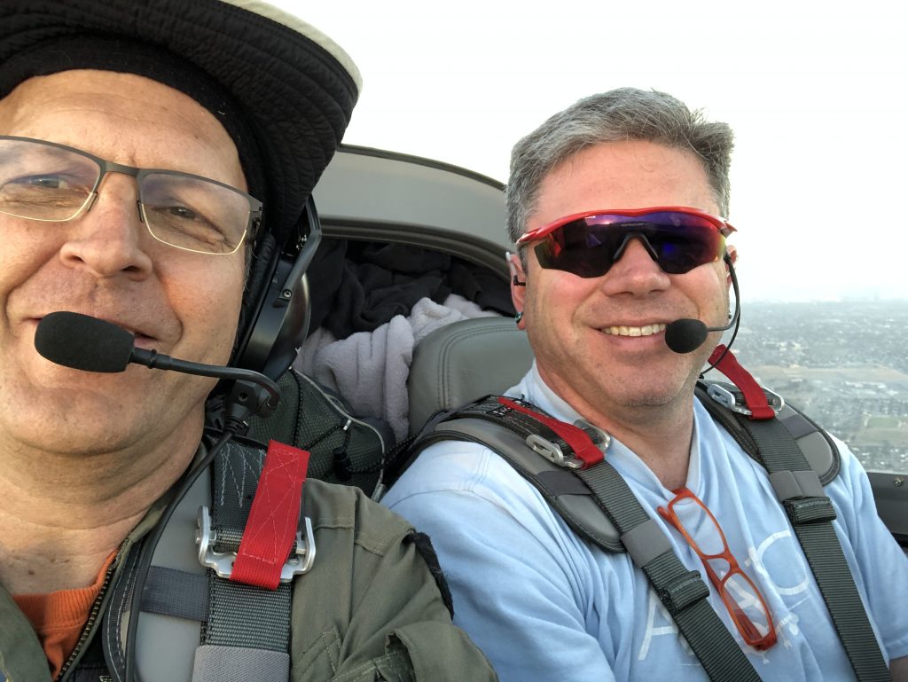
My buddy Marc heard I was heading back and that I’d have an open seat. He quickly messaged me and we arranged to leave the next morning.
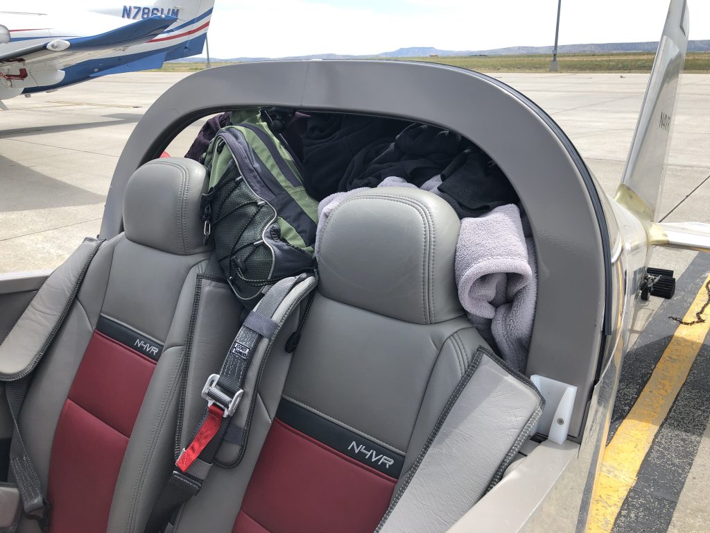
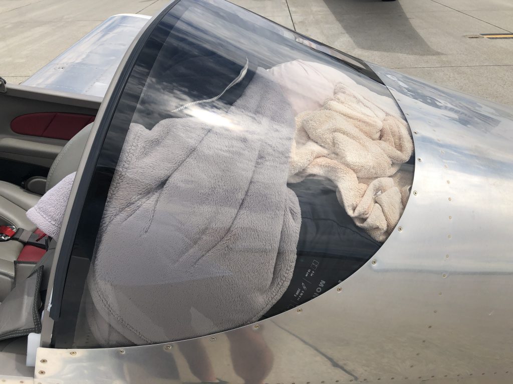
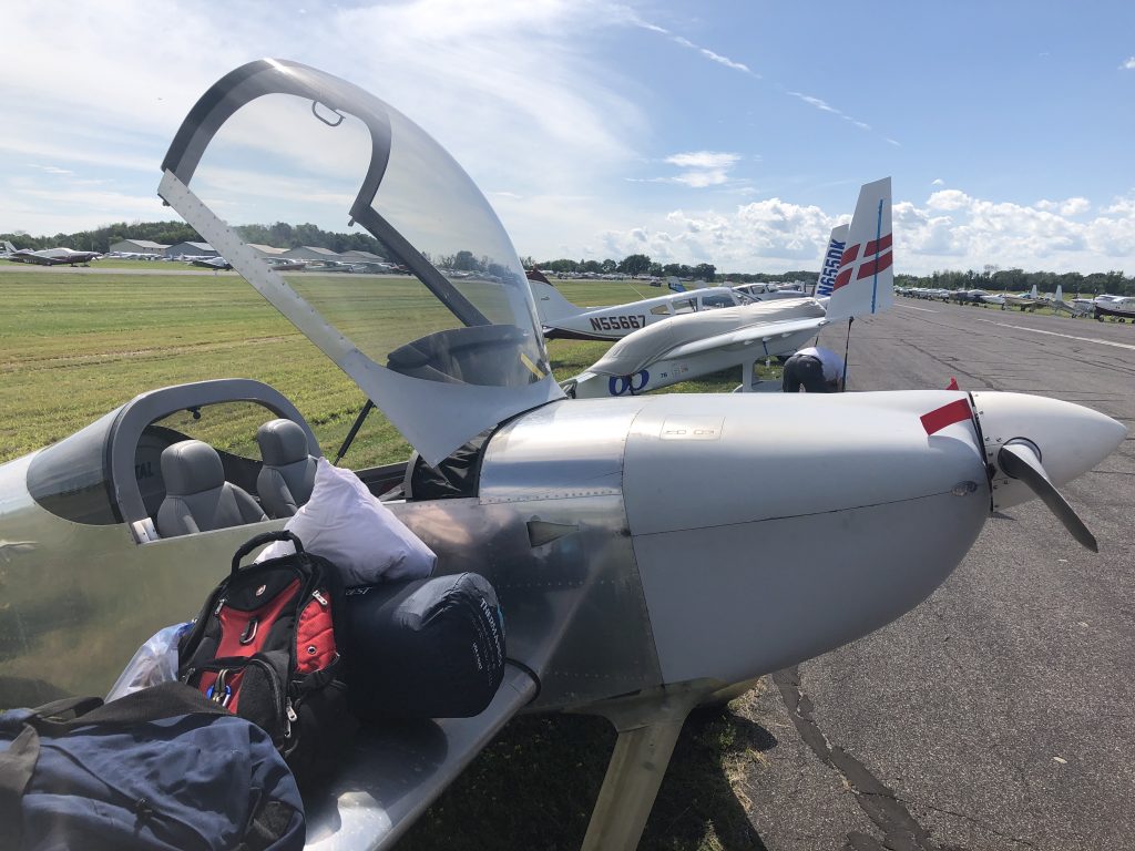
With two of in the plane, we were packed to the top of the rear window.There literally wasn’t a tiny bit of space remaining in the back.We even had to put some gear under our legs, both for space and CG reasons.We made it to Yankton, SD with one fuel stop and were lucky enough to grab a spot in a hangar since there was a storm forecast with the possibility of hail. The storms in the area had already soaked the campgrounds at Oshkosh, so arrivals were closed anyway.

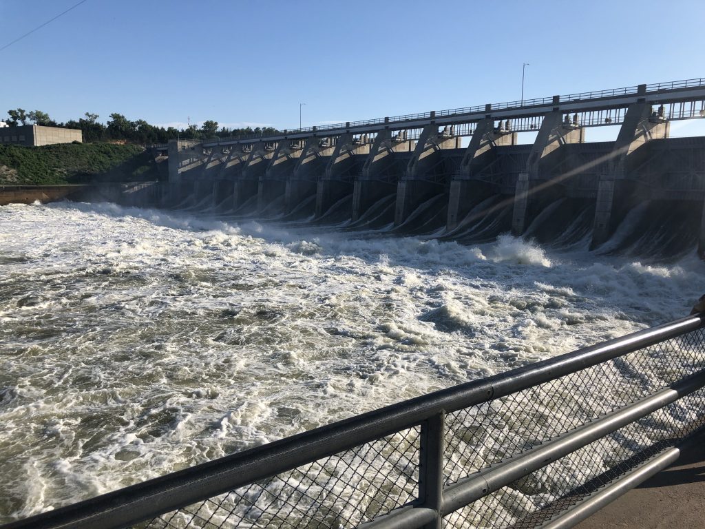
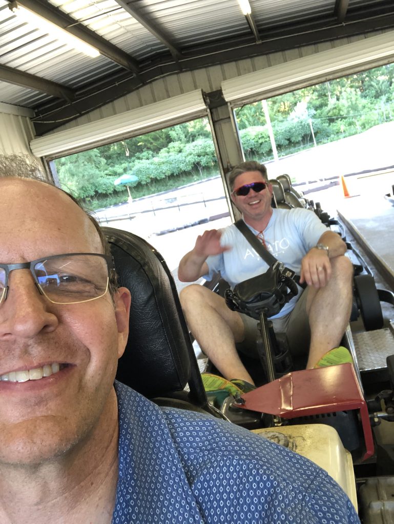
Yankton, SD was a fantastic place to stop for the night. In addition to the lowest fuel prices for 100mi, the local EAA chapter provided breakfast, lunch, and dinner as well as snacks and drinks 24/7. The FBO even remains open and allows people to sleep on the couches and recliners.We got there mid-afternoon, so we borrowed one of the two crew cars and went exploring. We visited the Gavins Point Dam.The dam was releasing tens of thousands of cubic feet of water per second, and it was really impressive to stand next to it.We found a go-cart track on the way back from the Dam and and Marc and I had some fun sliding these carts around the track.After a good night’s sleep in the FBO and a big breakfast, we started figuring out a game plan. Arrivals were still closed, but we thought it might be a good idea to at least head to an airport that was a little closer to Oshkosh, so we could get airborne quickly when arrivals opened. We flew over to Waupaca, and waited for a bit there with a bunch of other pilots also headed to Oshkosh. After awhile, we heard that they weren’t expected to open arrivals soon due to another approaching storm, so they suggested we find another place to park.

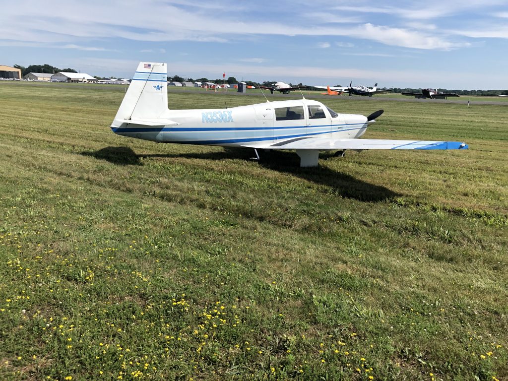
Marc had a buddy driving up to Oshkosh, so we decided we should fly to Fond Du Lac and leave the plane there. He could pick us up and we would drive the rest of the way. When we arrived, the ground was soaked, so they lined us up along both sides of the taxiways with our main gear right at the edge. Being a taildragger, this meant that my tailwheel was deep in the mud. I couldn’t even walk around the back of the plane because the ground was so soft.A Mooney driver thought it would be easier for him to taxi into the grass and then turn around and pull up to the edge of the taxi way. He immediately sank to his axles in the mud and came to a halt. Even with full power, he couldn’t budge.

He climbed out of the plane and started demanding the ground crew bring equipment over to retrieve his plane, but they were already overwhelmed with the hundreds of aircraft that had landed and politely refused. He was being a real asshole to the ground crew, but they stayed polite. I doubt they were able to retrieve the plane until days later when the ground firmed upJust as we had finished unloading the plane, we heard Oshkosh was accepting arrivals and we quickly threw everything back in the plane and started up as quickly as possible. There were a few Pipers and Cessnas ahead of us, but I kept the power in and we blew past them to be one of the first few from Fond Du Lac into the arrival.

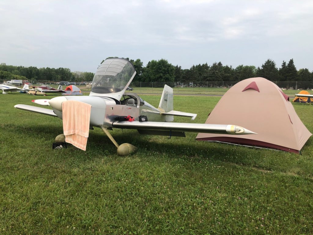
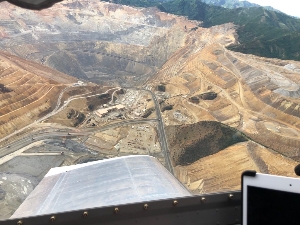
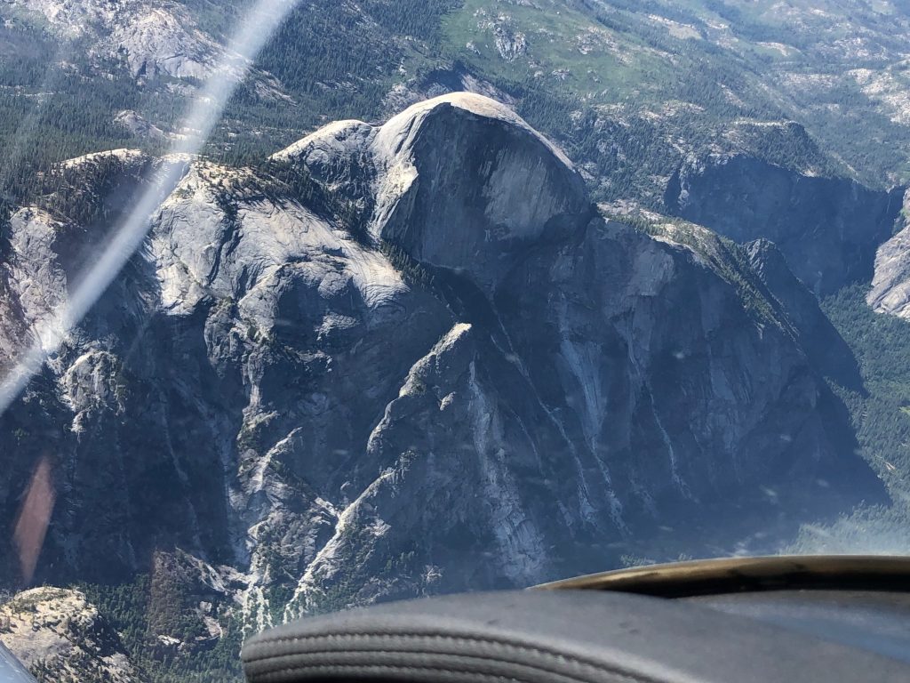
The arrival itself was pretty uneventful, and we quickly found ourself in homebuilt camping. It was going to be getting dark soon, so we quickly set up the camp and then headed off to find some food for dinner.After an enjoyable few days at the show, we headed out and stopped to visit my family in Salt Lake City for the night. Our departure the next morning took us directly over the Kennecott Copper Mine, so we circled once while climbing to get some pictures. The mine is the largest man-made excavation, and deepest open-pit mine in the world. It was actually hard to spot the mining trucks heading spiraling up and down the road from the bottom of the pit, despite the fact that these trucks are the size of two-story homes.We headed west and ended up flying directly over Yosemite where we circled a few times to get some good pictures of Half Dome as well as El Capitan and other sitesThe plane crossed 350 hours during the trip. It’s truly a joy to have a plane which enables us to take amazing journeys like this with the freedom to stop at interesting places along the way.

Complied with SB 14-01-31

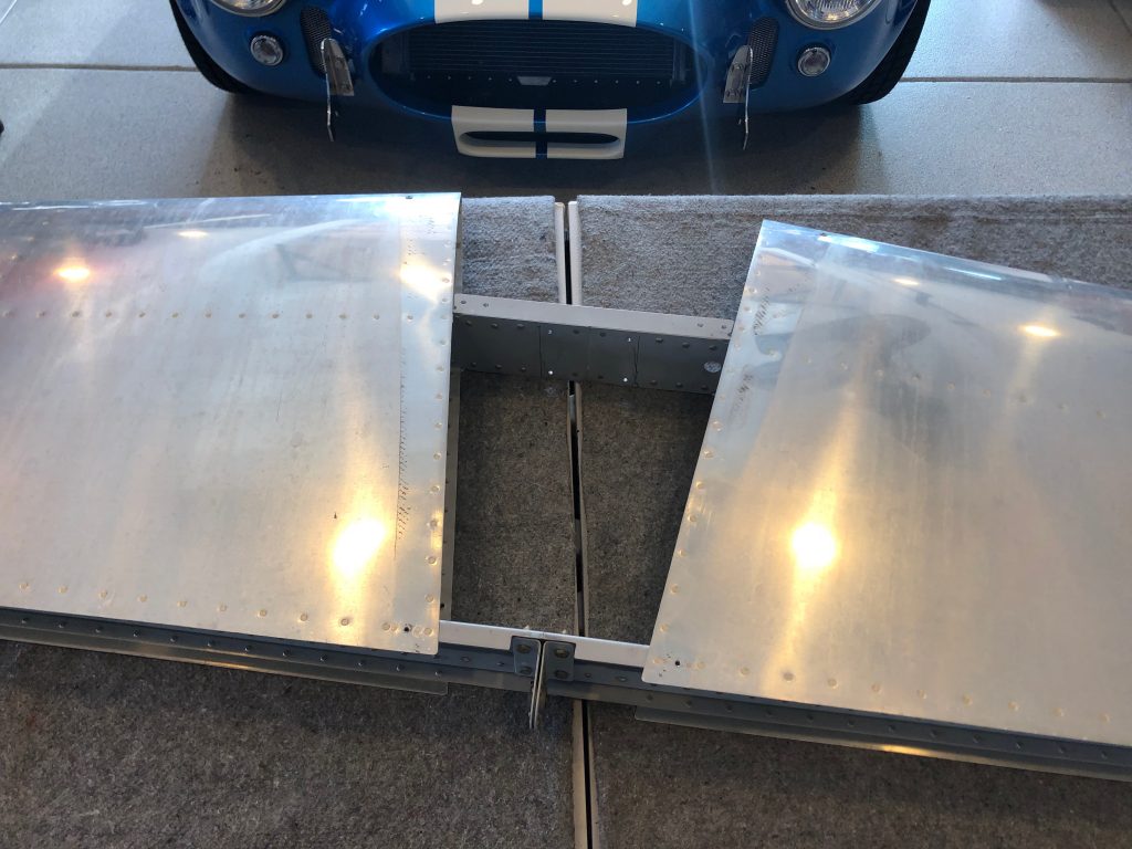
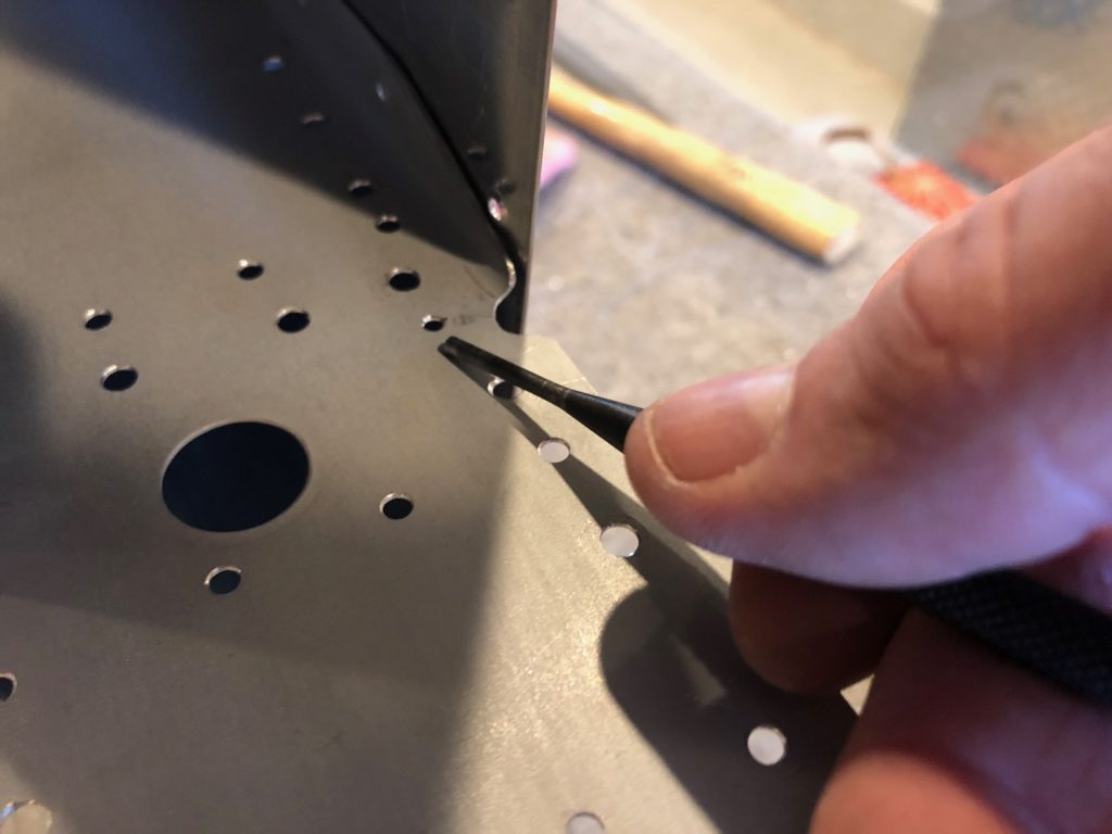
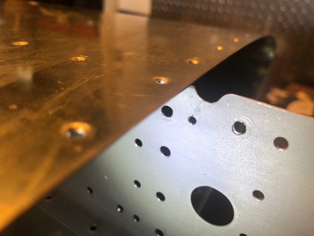
While inspecting the plane for this year’s condition inspection, I discovered the dreaded crack near the bend of the forward horizontal stabilizer spar. You can see the crack emanating from the bottom of the u-shaped notch at the top of the spar.

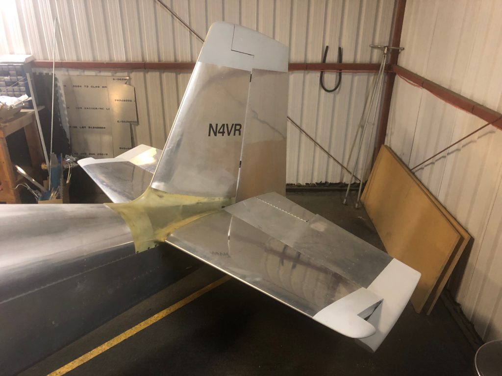
I came over bright and early one Saturday morning and disassembled the empennage in about 2 hours. I didn’t get any pictures of the process or the naked empennage, but you can imagine what it looks like.

I brought the horizontal stabilizer home since it will be much more convenient to work on here. My buddy Greg dropped by and helped me drill most of the structure. He brought some handy drill guides that helped us hit the center of each rivet (though we still buggered a few).

I didn’t get too many pictures during the process, but I did do a few things differently than the SB specifies. The SB asks you to drill out only the first two rivets along the forward spar so that you can slide a thin stainless steel shim between the skin and spar to protect the skin when trimming the spar. I decided to drill out a couple of additional rivets.

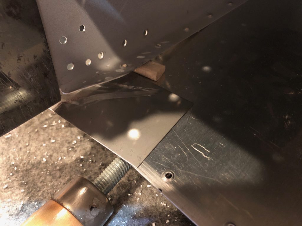
This allowed me to wedge in a thin (1/4″) wood piece to space the spar away from the skin. Not only does that help protect the skin, it makes it far easier to smooth out the cut after trimming the spar.

I also cleco-clamped a putty knife to the spar web at the bend to protect the spar from the Dremel wheel. I’m really glad I did this as I bumped it several times during the cut and I know I would have damaged the spar.

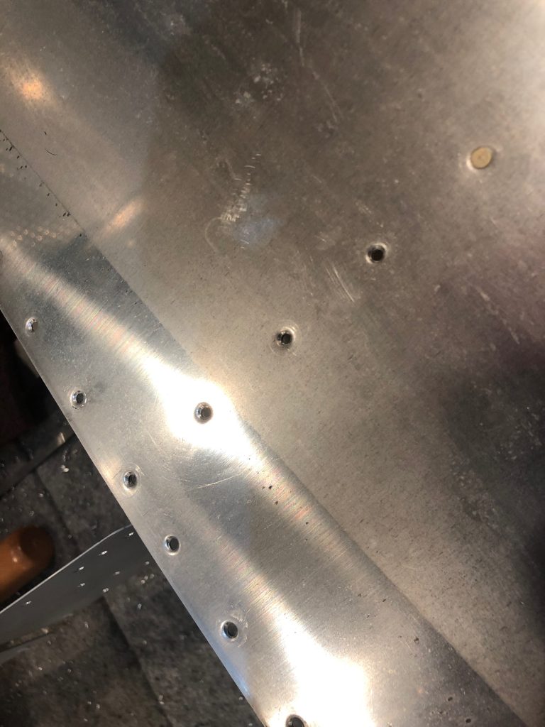
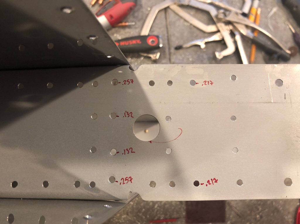
There were a handful of holes that were unfortunately elongated slightly. I decided to step these up to -5 rivets and drilled the holes out with a #20 bit. It was a slightly different set between the left and right side, so I decided to drill out some additional holes so that the -5 rivets were symmetric between each side. Fortunately, all holes turned out nice and round after doing so. I thought I might need to install cherrymax rivets in these holes, so I calculated the grip length for each hole based on the material stackup. I ended up shooting a bucking solid AN470 rivets in every holes.

After carefully finding the end of the crack, I stop drilled it with a #40 bit and deburred it.
I didn’t get a picture, but I elongated the hole toward the crack slightly and then smoothed everything out.
Greg dropped by a couple more times to help me rivet the structure and reassemble it. The plane was down for about a week, but I’m glad to have this behind me and know that it’s far more robust than it was before.

Added Oil Cooler Quick Drain

Saf-Air recently released an adaptor that allows you to add a quick drain to an AN fitting. My oil cooler has a tee fitting at the lowest point that I installed a cap on, but draining the oil from this point was always a bit of a pain. The adaptor lets me replace the cap with a quick drain that I can attach a hose to.

Unfortunately, my oil cooler was too close to the firewall for me to install it directly on the tee, so I needed to add a 90º fitting to point the assembly downward. I assembled the pieces on the bench since it was much easier to safety wire this way.

I then installed the assembly to the tee on the lower port of the oil cooler.

The quick drain points slightly forward and nicely clears the engine mount and brake line.

Pulled ELT and Replaced Batteries

After the ELT was triggered on the return from KY, I called ACK and they said the most common reason I could have experienced the issue was moisture in the audio remote. Fortunately, ACK is located right here in San Jose, CA, so I dropped by their office one morning on the way into work with the ELT and audio remote.

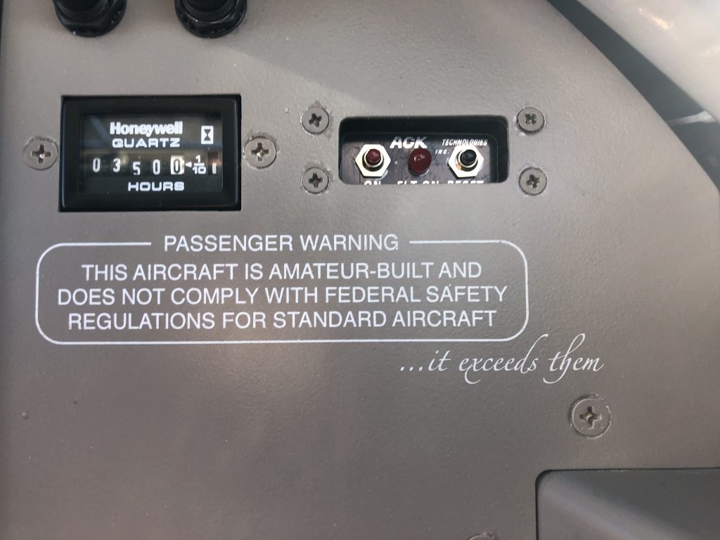
Fortunately, there was no moisture in the audio remote, but they replaced the battery while they had it open. They also opened the ELT to see if there were any issues there. I had one of the very first units and they said they had some issues with the early digital boards, so they replaced it at no charge. I also picked up a new ELT battery for $100 since it has to be replaced if the ELT transmits for more than 1 hour. Finally, there’s a battery in the panel mounted remote that needs to be replaced every 10 years. Even though mine was only 7 years old or so, I went ahead and replaced it so that the ELT won’t need any servicing for the forseeable future.

I had forgotten that I didn’t add nutplates to the subpanel for attaching the audio remote, so getting the nuts off was a bit of a pain in the ass. I knew it would be even more painful to reinstall them, so I used a couple of Command Adhesive strips. These can hold 3 lbs each and this whole unit only weighs a few ounces.