Swapped Propellers

The RV-7 was designed before the days of composite constant-speed propellers, and was further designed for the 200hp, angle-valve IO-360 motor. Taking Van’s advice to build the lightest plane possible, I opted for the WhirlWind Aviation 200RV composite prop and the much lighter IO-375 motor. This meant I was approximately 70lbs lighter in the nose than the plane was designed for. This put my C.G. much farther aft than typical, and it was in fact easy to load the plane aft of the aft C.G. limit.

I spoke with Van for a bit at a party last year, and he indicated that the easiest change to make (short of just bolting on some weight) would be to switch to an aluminum constant speed propeller. When my 200RV prop started slinging grease back in the spring, it seemed like the perfect time to do the swap.

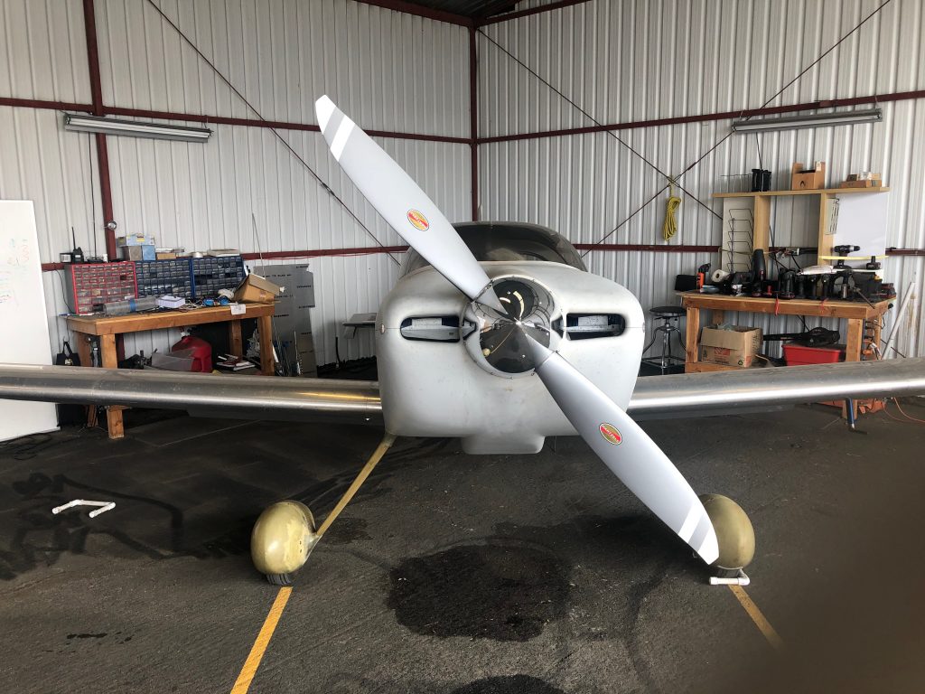
I ordered the Hartzell C2YR-1BFP/F7497 through Van’s. This is a 74″ prop and not normally recommended for the RV-7 due to being 2″ longer than the 72″, recommended prop. However, I spoke with someone at Hartzell, and he indicated that there were advantages in thrust with the 74″, and the extra weight only helped my situation. The only downside for me is reduced ground clearance. The 200RV had 8 3/8″ under normal gear compression in a level attitude, so this prop should have 1″ less, or 7 3/8″. In a hard landing, or if I inadvertently raised the tail too far, this would be reduced. However, I virtually always fly off hard surface runways and generally do tail-low wheel landings, so I’m not particularly worried about the reduced clearance.

The prop shipped 4-6 weeks later and pretty quickly landed at the UPS hub in San Jose, CA where I live. Unfortunately, UPS then lost track of it for three weeks! Eventually, it turned up in a trailer full of packages that apparently sat unopened that whole time. I dropped by their hub and picked it up and brought it to the hangar where I opened it and got it ready to mount on the plane.

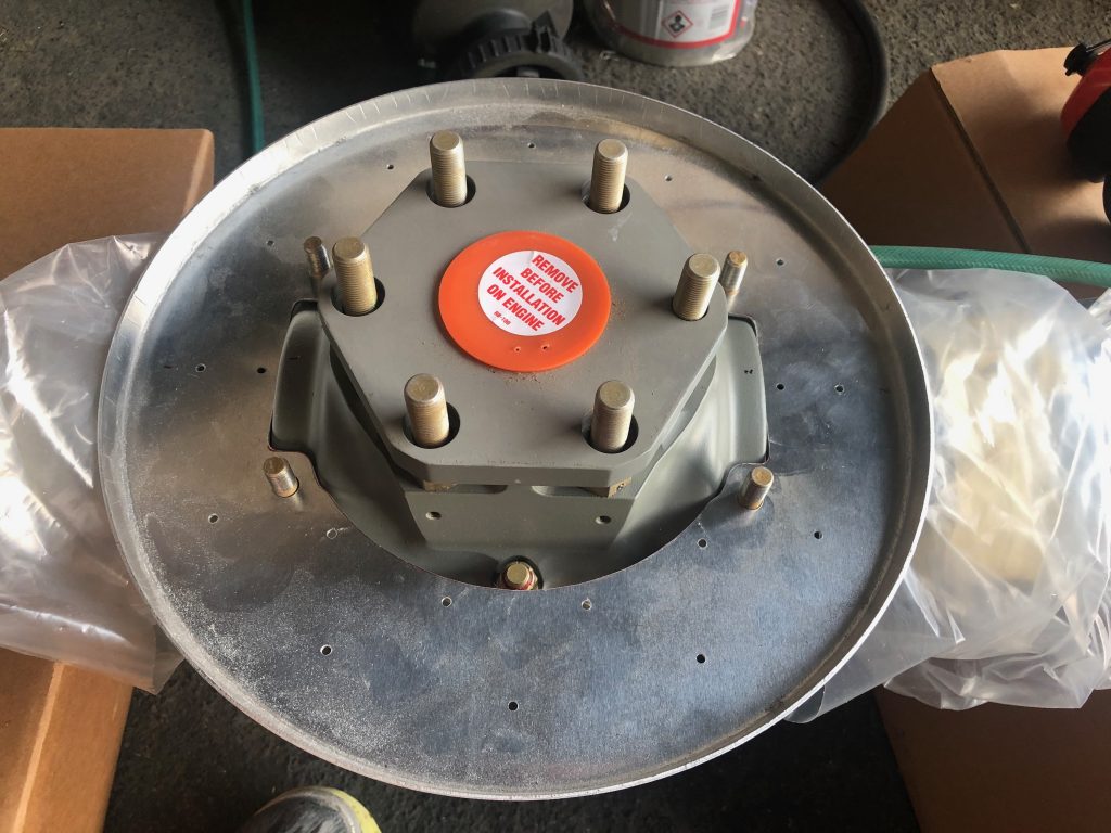
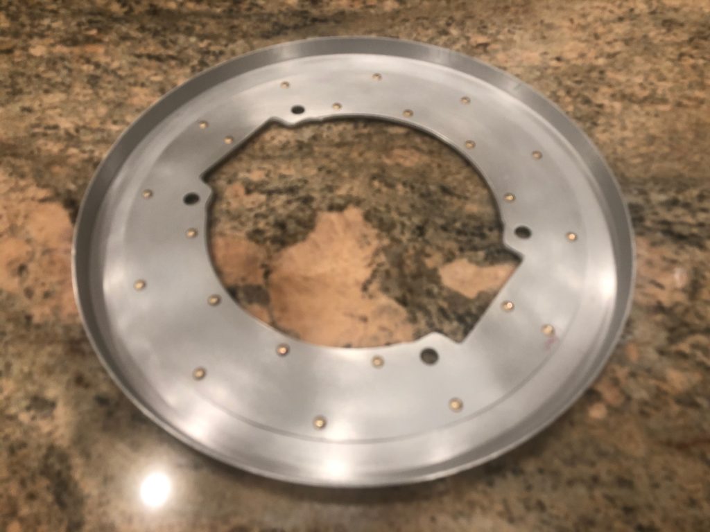
The first step is fitting the rear spinner bulkhead. This needs to be cut to match the doubler and then relieved further to fit on the propeller without touching the hub itself.

My buddy Michael was kind enough to let me drop by his place and shoot some of the Stewart Systems primer on the front and rear bulkheads, then I riveted the two parts of the rear bulkhead together.

When everything was ready with the new prop, I pulled the old prop from the plane.

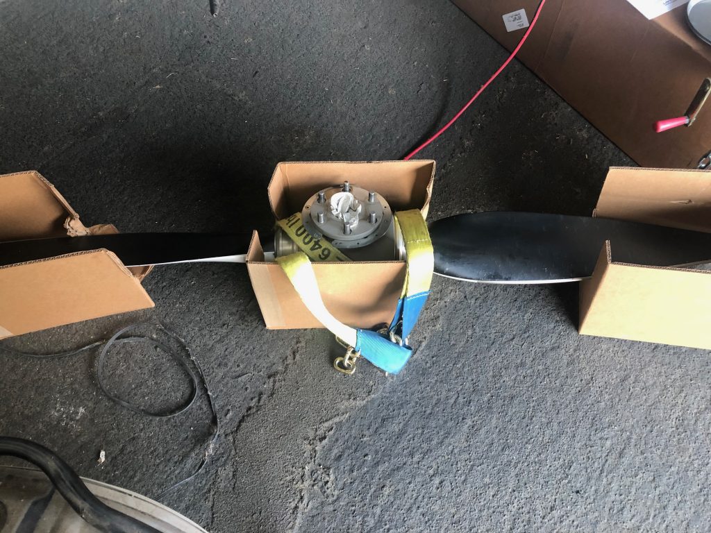
I’ve had some back pain recently, so I used this lifting sling with my shop crane to get the old prop off and install the new prop on the plane. This was far easier that trying to hold the prop with one arm while manipulating the bolts with my other hand.

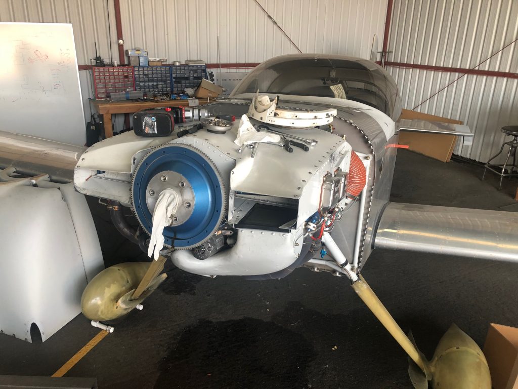
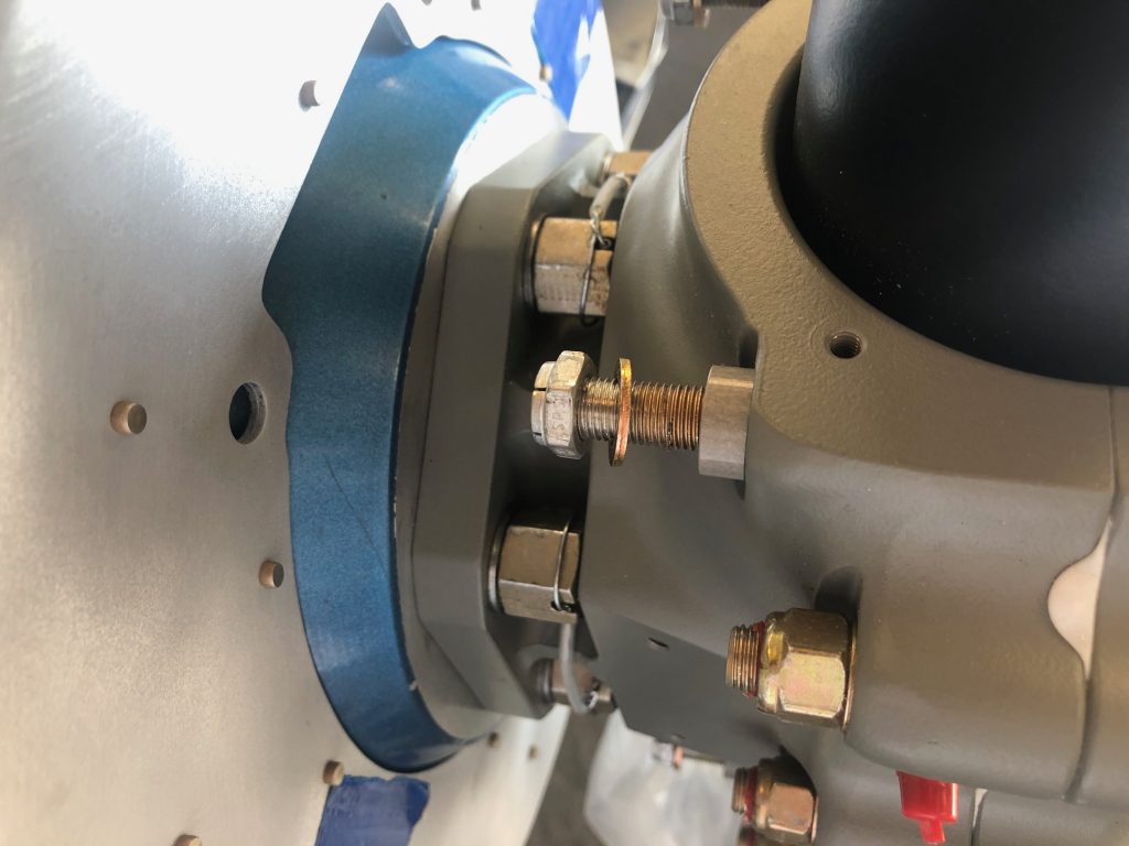
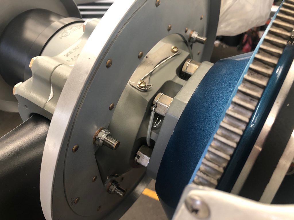
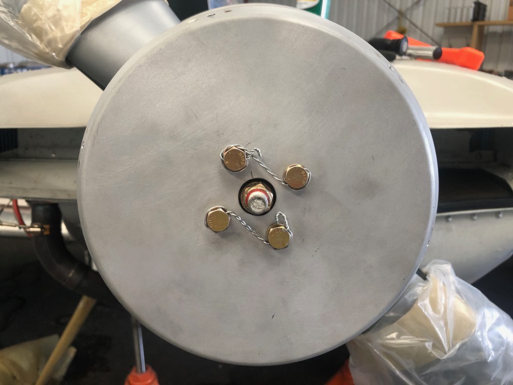
I taped the new bulkhead to the flywheel while installing and safety wiring the new propeller.

I then installed the rear bullhead to the hub retaining bolts and torqued them to spec.

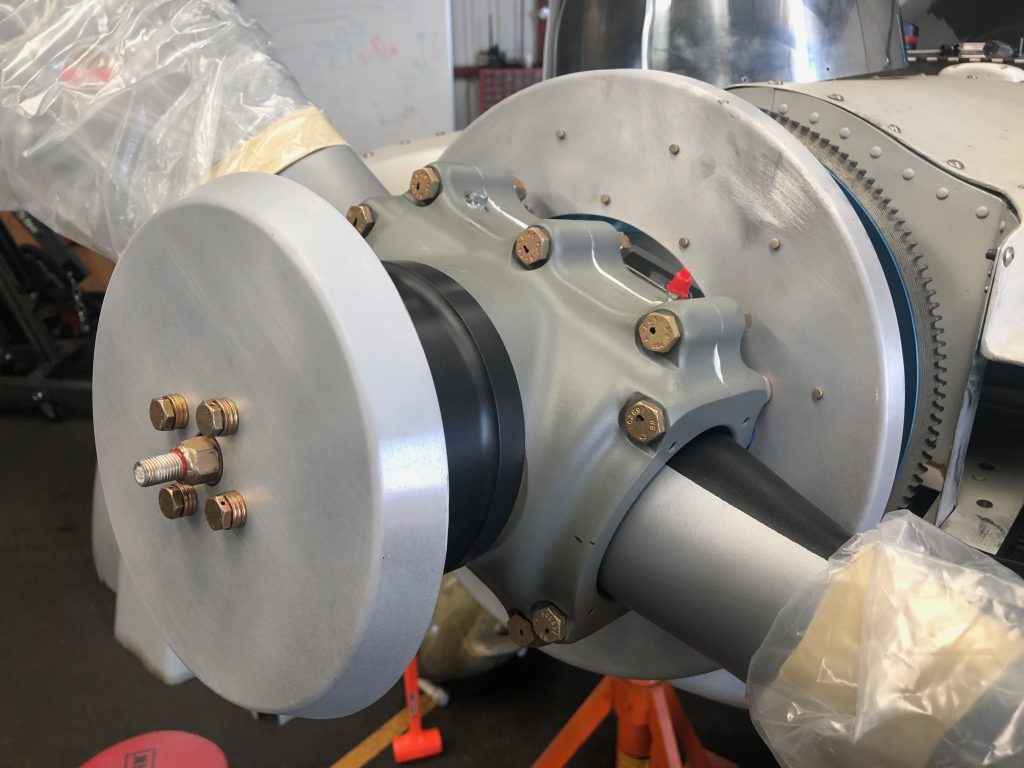
I temporarily installed the front bulkhead so that I could begin fitting the spinner.

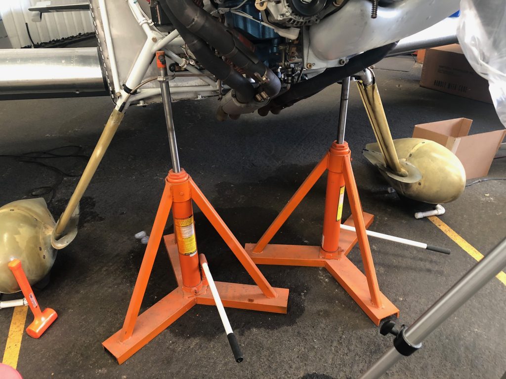
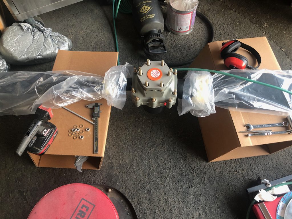
I needed to be able to turn the engine freely when fitting the propeller, but I needed it to be fairly stable. I used the same technique I did when fitting the wheel pants, and jacked the plane up by the engine mount. I then removed the lower spark plugs so that the engine could spin freely.

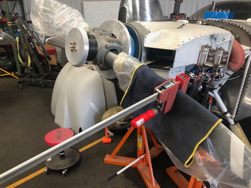
When fitting the spinner, I also needed to be able to cycle the blade from the fine pitch stop to the coarse pitch stop. I ended up using some padding and one of my Bessey clamps which worked perfectly. Here is the propeller at the fine pitch stop.

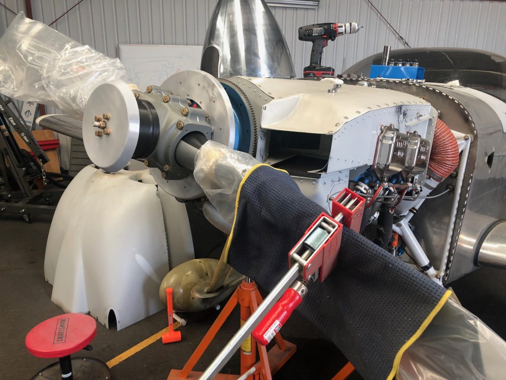
By just pushing down on the clamp (and holding the propeller tip to prevent it from rotating the engine), it was easy to twist the blade to the coarse pitch stop.

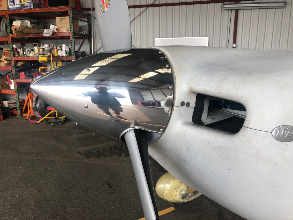
I’m using the Cummins Spinners spinner for this propeller. I emailed Alan back in the spring to inquire about purchasing one of these, but there was no response. Others online said that hadn’t been able to get ahold of him for over a year and a half! I gave up hope and ordered the spinner kit from Van’s, but just before install, I received an email out of the blue from Alan saying he had a spinner ready to ship! It took a couple of weeks to get here from Australia, but it’s worth it for the look of a polished spinner on the plane.

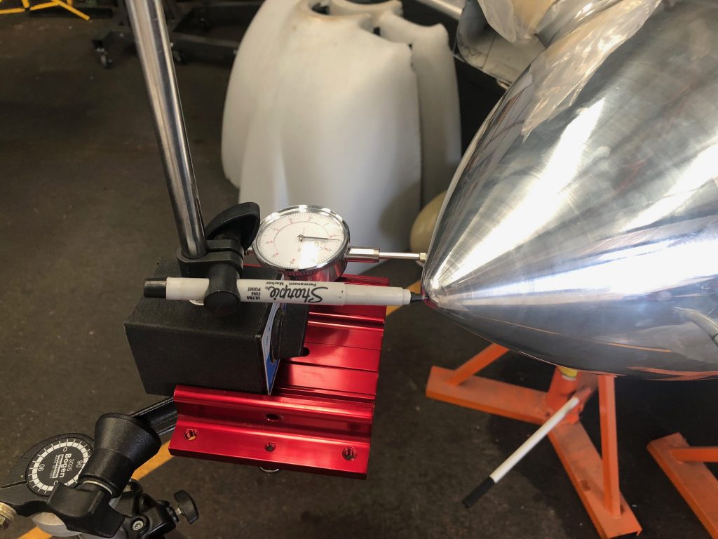
To ensure the spinner was centered, I used a combination of a marker at the tip and a dial indicator on the side to measure wobble. I think it’s impossible to get this to 0″, but I feel like I got pretty close. You couldn’t see any deviation with the marker tip and the dial indicator showed +/- 0.003″ deviation. Since the spinner is 0.065″ aluminum, that’s only about 5% of the thickness of the spinner!

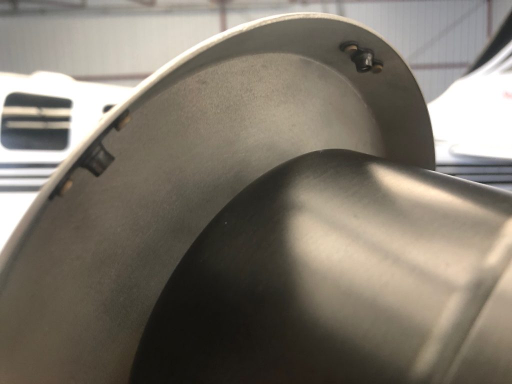
After drilling all of the holes, I set the nut plates on the front bulkhead.

…then safety wired it in place.

My buddy Greg found a metal polishing place about 45 minutes from my house, so I dropped the spinner off and had them polish it to a mirror finish.

Interestingly, the prop clocks at a different location when the engine’s stopped. The old prop would be level after shutdown.

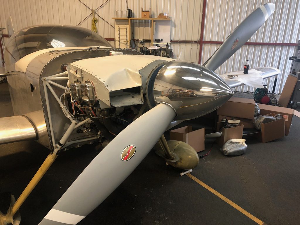
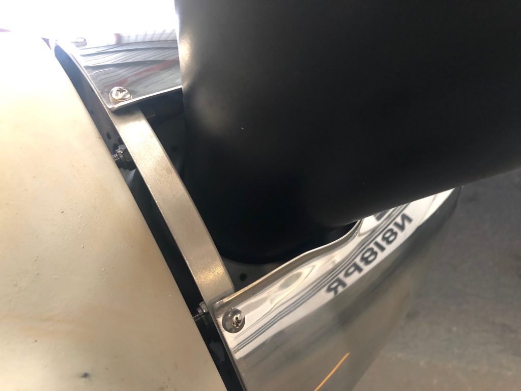
It looks like I’m going to need to raise the prop a small amount due to engine mount sag. You can see the misalignment of the spinner and cowling clearly here. The spinner sure does look sharp though.

I also need to fabricate filler pieces to fit behind the blades, but that can happen down the road a bit.

Replaced Fuel Flow Sensor

My fuel flow has been erratic again recently. This has happened a number of times and Electronics International has always indicated that the cause is almost always the electrical connections. I’ve tried crimp connectors, solder, solder sleeves, and finally their own OLC-1 and now OLC-2 connectors. Interestingly, the problem would always appear to be resolved for a bit, but would then reappear some number of hours later.

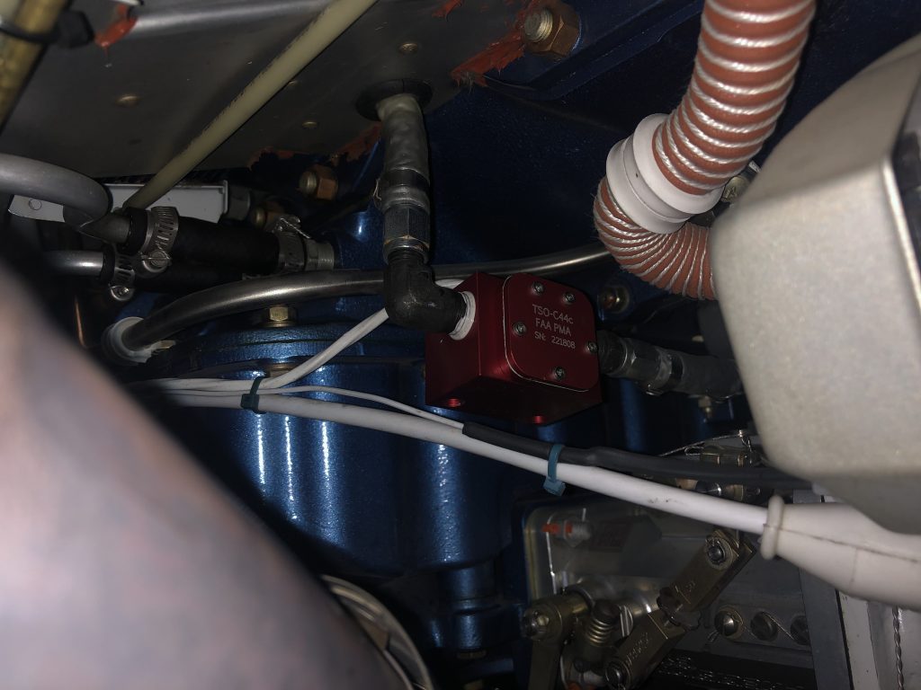
A friend mentioned that he’d had a similar experience and a replacement fuel flow sensor fixed it. Out of other options to try, I ordered one and installed it tonight.
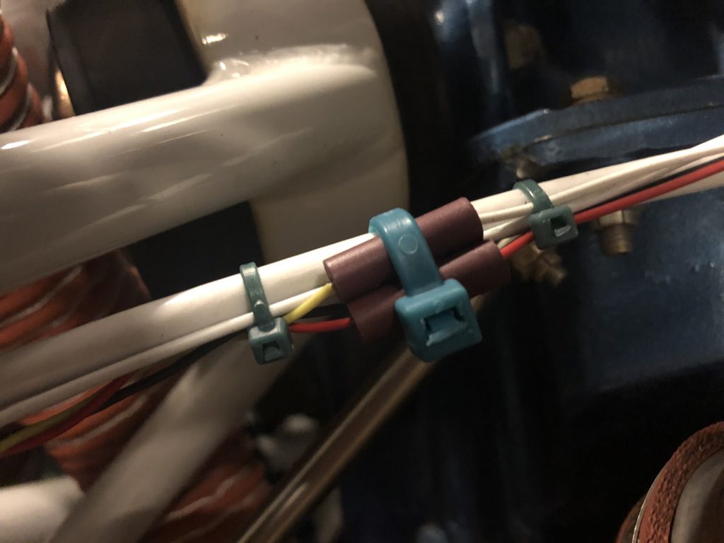
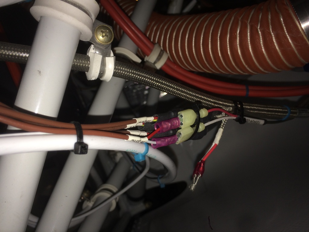
Their new OLC-2 connectors have two crimp screws per connector so you don’t have to try to hold both wires in place simultaneously while trying to tighten the screws. I don’t like how these connectors provide no strain relief for the wires, so I did my best to immobilize everything.
I leak tested everything and ground-ran the engine. Initial run showed nice, solid fuel flows.

Added Oil Cooler Quick Drain

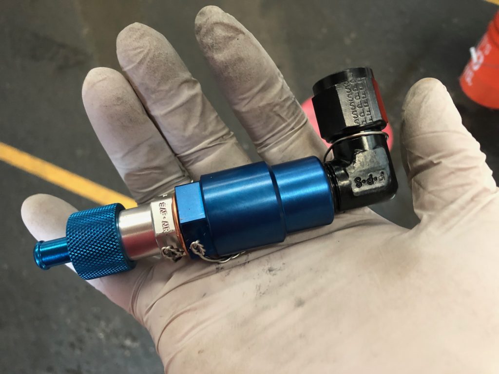
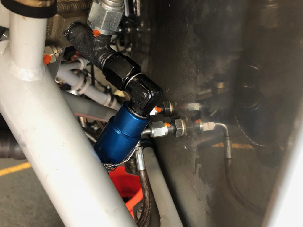
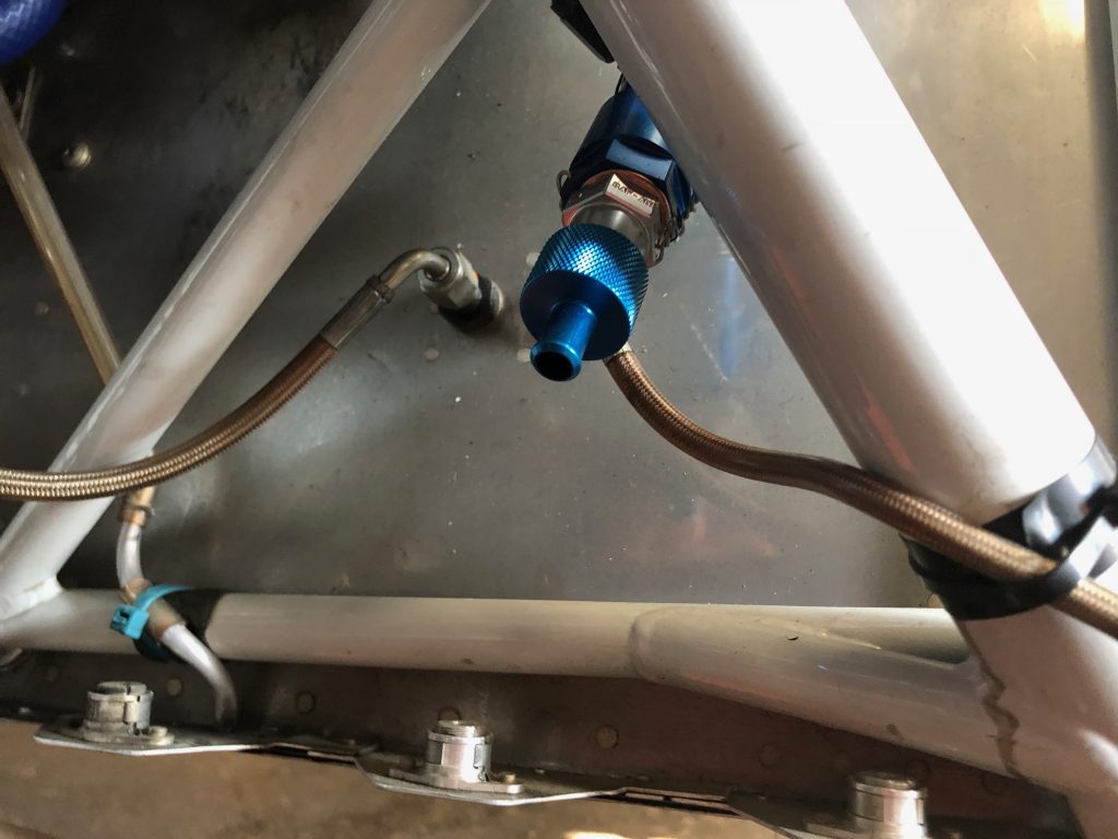
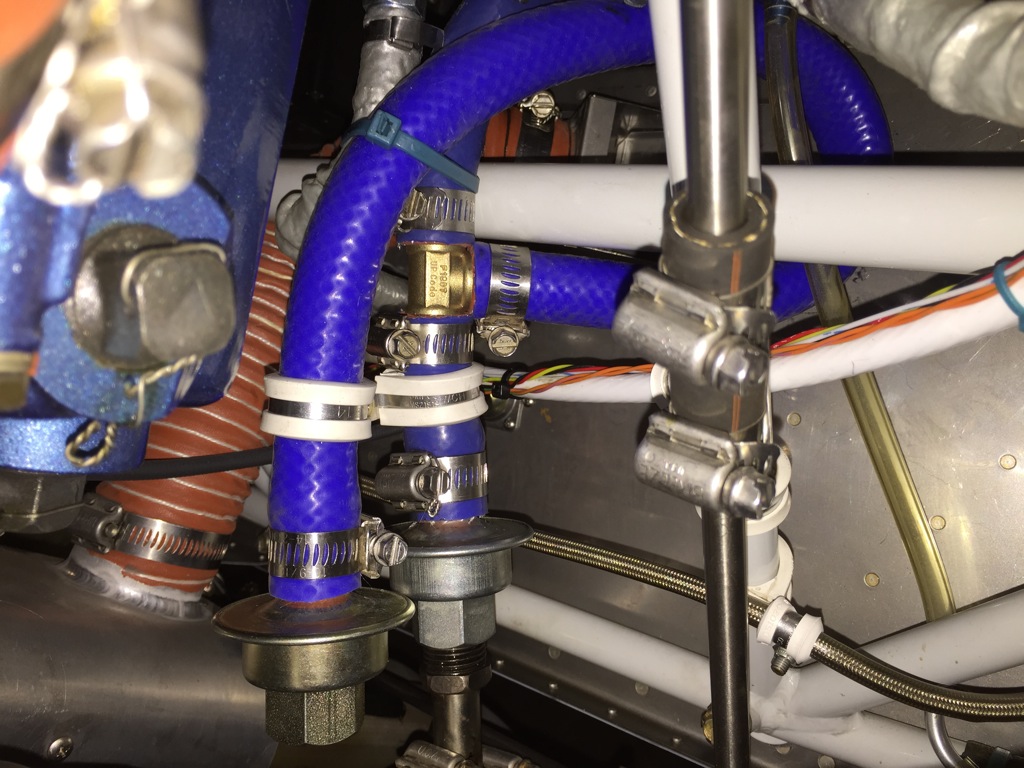
Saf-Air recently released an adaptor that allows you to add a quick drain to an AN fitting. My oil cooler has a tee fitting at the lowest point that I installed a cap on, but draining the oil from this point was always a bit of a pain. The adaptor lets me replace the cap with a quick drain that I can attach a hose to.

Unfortunately, my oil cooler was too close to the firewall for me to install it directly on the tee, so I needed to add a 90º fitting to point the assembly downward. I assembled the pieces on the bench since it was much easier to safety wire this way.

I then installed the assembly to the tee on the lower port of the oil cooler.

The quick drain points slightly forward and nicely clears the engine mount and brake line.

Replaced Heater Valve

I recently noticed that my cabin heat wasn’t working. After a quick inspection, I realized the control arm on the heater valve had broken off of the flapper valve. The valve is a stainless steel unit from Plane Innovations which I upgraded to because I wanted to keep all steel components on the firewall.  I emailed the company about the best way to repair the valve and they rushed out a new one free of charge. I wish more companies had this kind of customer service.

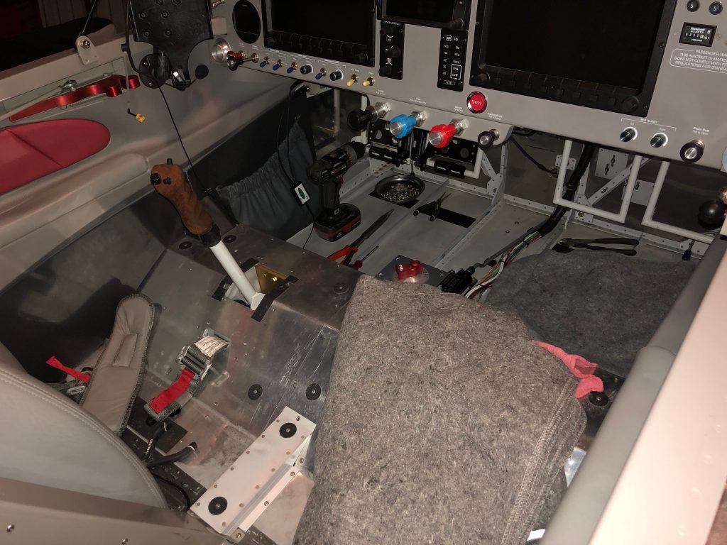
Unfortunately, getting the old valve out requires pulling a substantial amount of the interior out. The heater valve is behind the tunnel cover which is under the fuel pump cover. The fuel pump cover sits under the forward seat pans, so the seats and carpets need to be removed.

My son helped me remove the nuts holding on the heater valve. This is one of the few items that regrettably I didn’t attach to the firewall with nutplates. It would have made replacing it far easier. Unfortunately, adding nutplates now is virtually impossible, so we just bolted the new one on the same way.

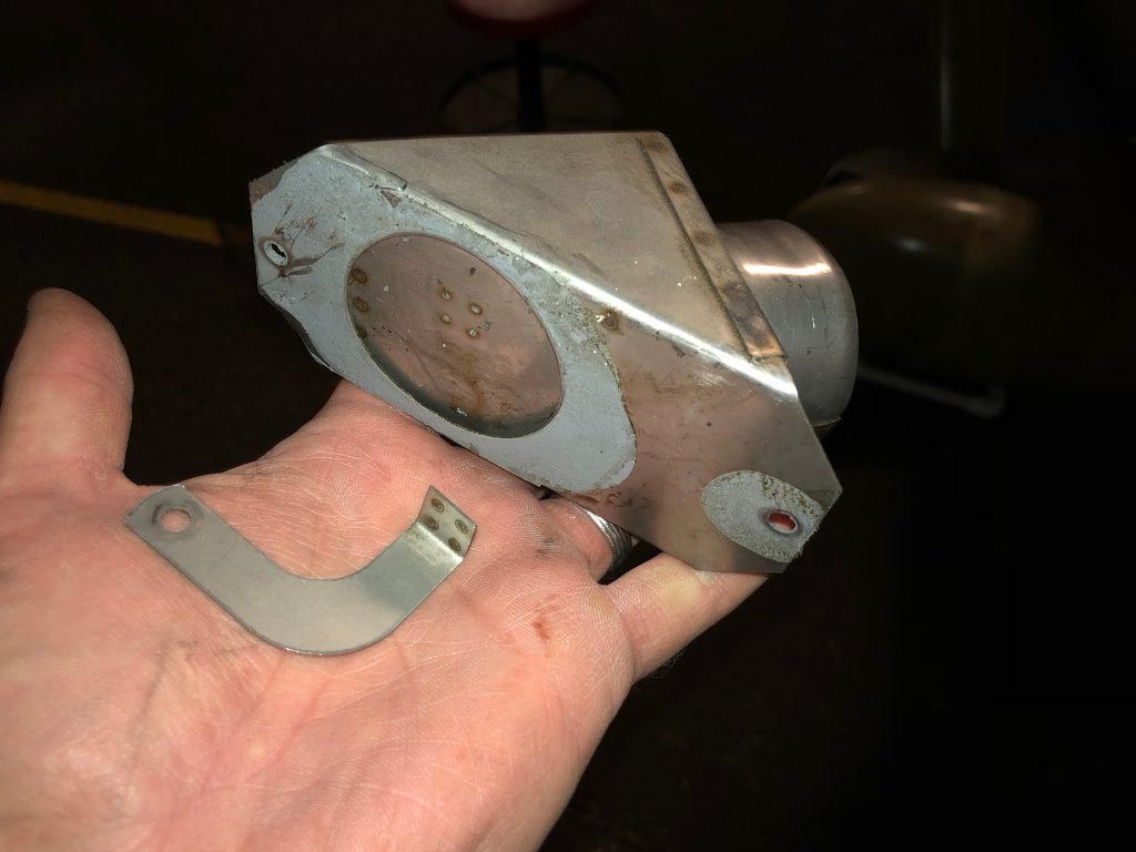
Here’s the failed heater valve. The spot welds simply failed due to the high vibration around the firewall. The new valve has five spot welds instead of four, but I’m not optimistic this will prevent this from happening again.

Broken Exhaust Support

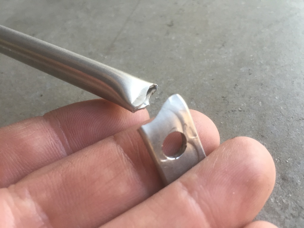
While taxiing in from a flight, I heard an odd clunk. I took off the cowling to do a careful inspection and found that both exhaust supports cracked all the way through right at the bend. Squeezing this tubing flat and then bending it clearly put too much stress in the metal.

The bottom of the support just has a flattened piece of stainless steel tubing bolted to a bent piece of mild steel. The mild steel is much tougher and can withstand the vibration without cracking.

I replicated this arrangement at the other end of the supports.  Fortunately, it was a pretty quick fix and this should be much more durable.

Modified Breather Vacuum Valve

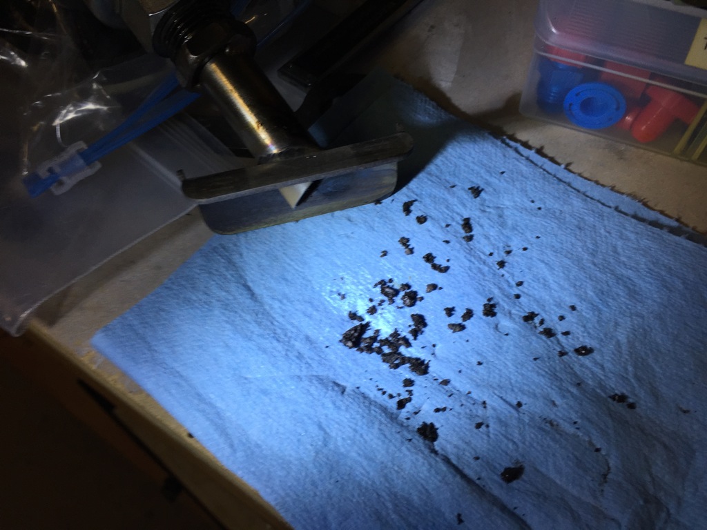
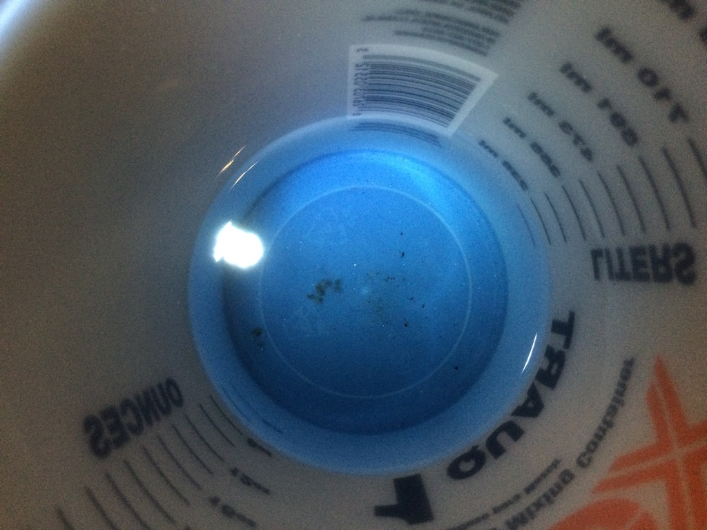
There is a thread on Van’s Air Force about carbon build up in the breather tube.  I pulled the tube off and there was some build up (maybe 10% of the cross-sectional area of the tube).  Most could be easily removed with a pick, but I used a wire brush to get the inside of the tube totally clean.  Here are all of the carbon bits that came out of the tube.

If this tube were to totally close off due to carbon buildup, it could pressurize the crankcase and blow out the front oil seal.  To prevent this, I put a T in the breather line and ran that to a second vacuum valve positioned above the exhaust pipe to burn off any oil that might drip out.

Fabricated New Exhaust Support and Replaced CHT Probe

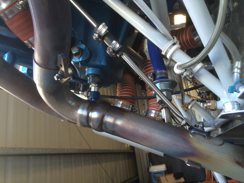
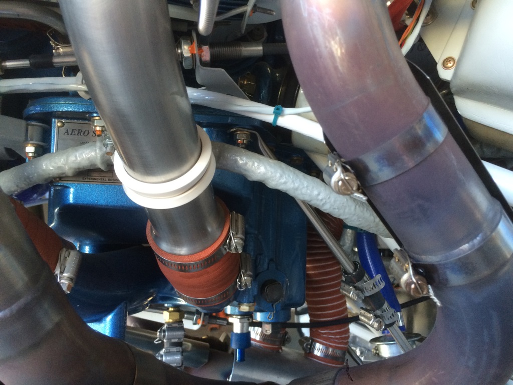
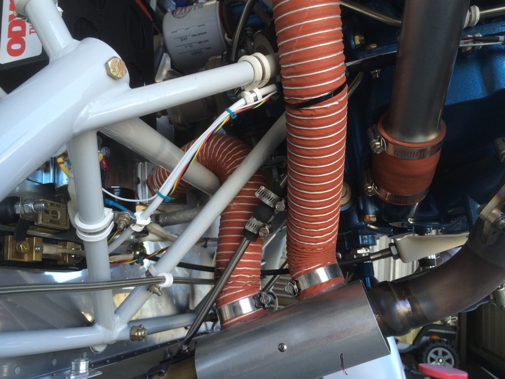
I needed to move the exhaust support tubes outward to clear the SCAT tubes going to the heat muff.  Sadly, I didn’t get any pictures while the cowl was off, so I tried to take some pictures of what I did through the openings in the cowl.  I replaced the aluminum bar that ties all four pipes together with one that is 4″ longer.  I drilled additional holes in each end to attach the clips that tie the stainless tubing to the bar.  This moves these supports out about 1 5/8″ on each side.

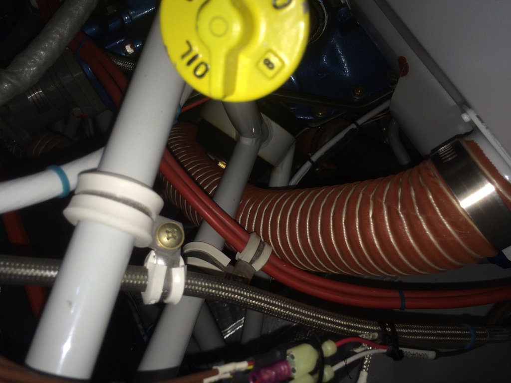
I rerouted both SCAT tubes and replaced the piece that was worn by rubbing on the exhaust support.  Now there is plenty of clearance all around.  This piece of tubing now runs above the lower engine mount tubing so it doesn’t rest against the wire going to the alternator.

It’s pretty tough to see here, but the SCAT tubing from the heat muff to the firewall valve now runs under the horizontal tubing on the engine mount.  This shortens the tubing and provides a more direct path into the heat muff.

I received a new CHT probe from Aircraft Spruce, so I installed it to see if the problem was the probe of the connection.  This probe works just fine, so I’m going to redo the connections on the other one to see if the problem comes back.

Fabricated New Exhaust Support Brackets

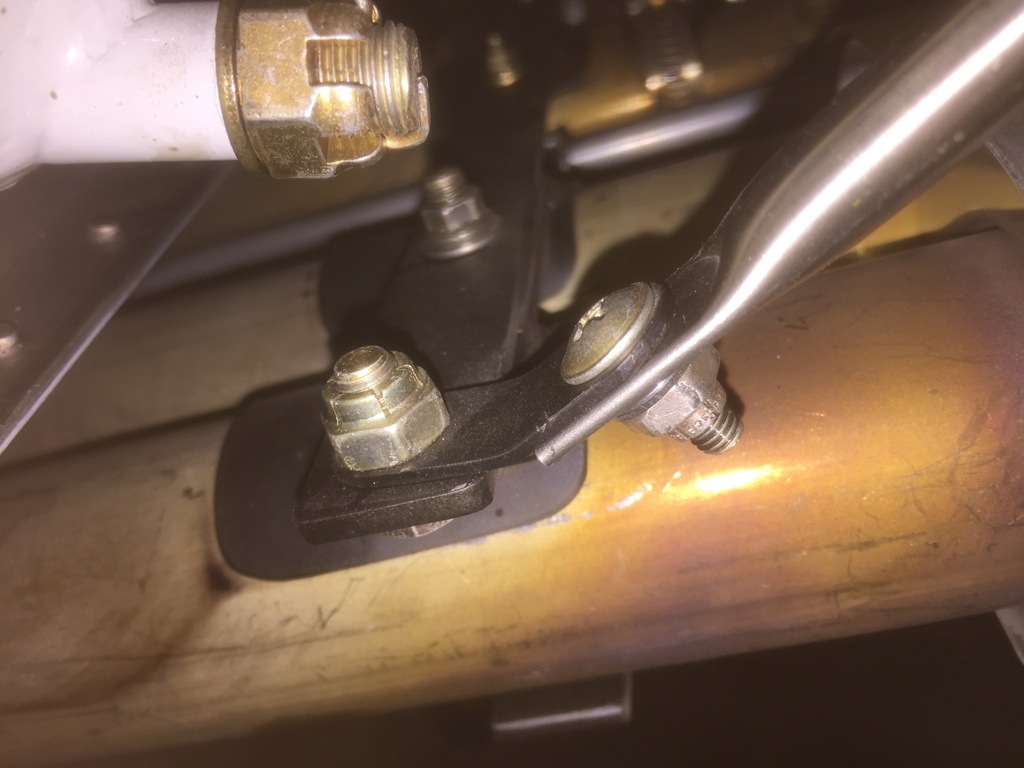
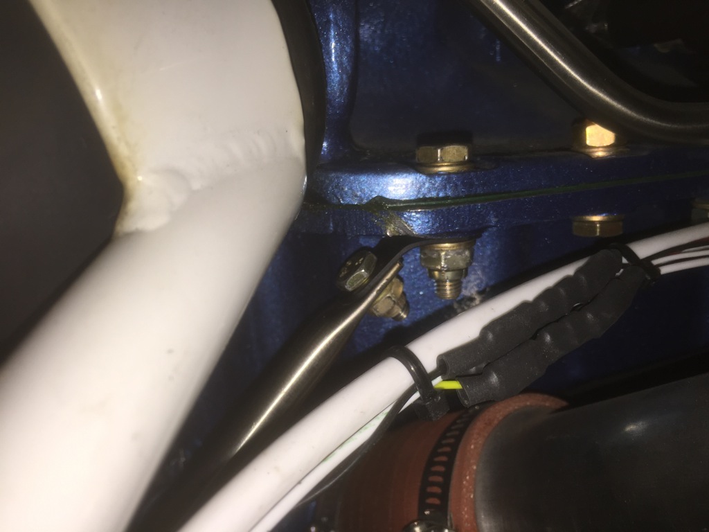
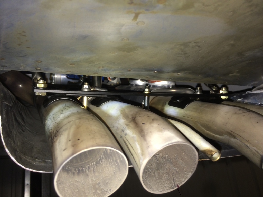
One of the things I’ve been needing to do is replace my exhaust supports.  I originally built them to the plans from Vetterman Exhaust which involved supporting them from the engine mount.  This puts stress on the exhaust as the engine shakes at startup and shutdown since the exhaust can’t move with the engine.  It’s better to support the exhaust from the sump so that it can move with the engine.  I ordered some 0.035″ wall thickness, 3/8″ OD stainless steel tubing and some MIL6000-6 rubber tubing which is the same as what came from Vetterman.  I cut the tubing to length and flattened each end so I could drill holes and bolt it to the sump and exhaust support.  There is about 1/4″ gap between the upper and lower tube, and I put a small flare in the end to keep the tubing from pulling out.  Here’s the lower end of the left support.

You can see the upper end has a bend to align with the sump.

Here’s the left side.  This support runs tight against both pieces of SCAT tubing.  I’ll keep an eye on this for chafing.  If it does, I can fabricate a bracket to move the lower attach points outward and then reroute the forward SCAT tube so there is no interference.

Restored Airplane to Flight Status

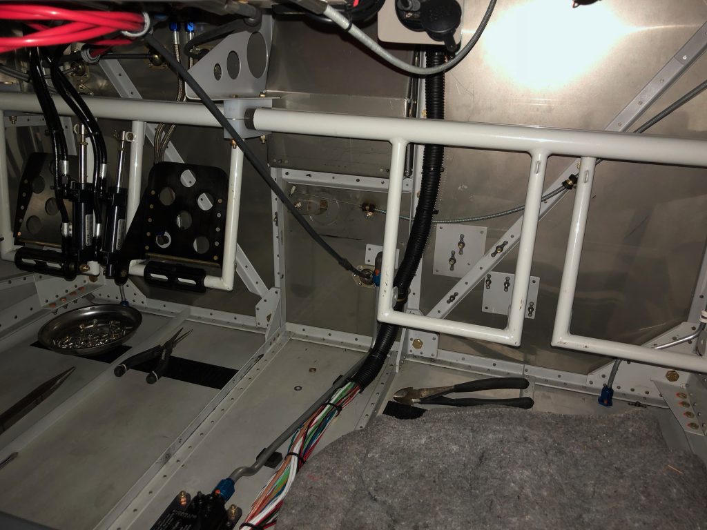
Since I had the aft baggage wall out to adjust the ADAHRS, I took the opportunity to inspect all of the elevator linkages and relubricate them.  I then vacuumed out the entire fuselage.  Despite doing this thoroughly before first flight, there was an amazing amount of debris including a large number of small metal particles from the drilling operation when assembling the fuselage.  I have no idea where these particles were hiding when I earlier cleaned out the fuselage.  I then reinstalled the aft baggage wall and all of the interior.

Before reinstalling the cowl, I adjusted the prop RPM again to hopefully get pretty close to 2700 RPM.  I also wrapped the fuel flow sensor with some extra thick fire sleeve and some safety wire.  It’s not the prettiest wrap job, but I’ll redo it if works.

SkyView Battery Test, Bowden Clamps and Fuel Filter Servicing

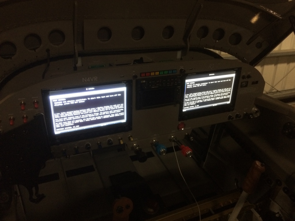
I previously sent the backup battery from my left SkyView screen into Dynon because it didn’t seem to be charging during the first few flights.  They charged the battery and tested it and it was fine.  They sent it back to me so I installed it tonight and ran the battery test on both screens.  Both passed by powering the screens for 45 minutes (and new batteries should power the screens for more than 1 hour).

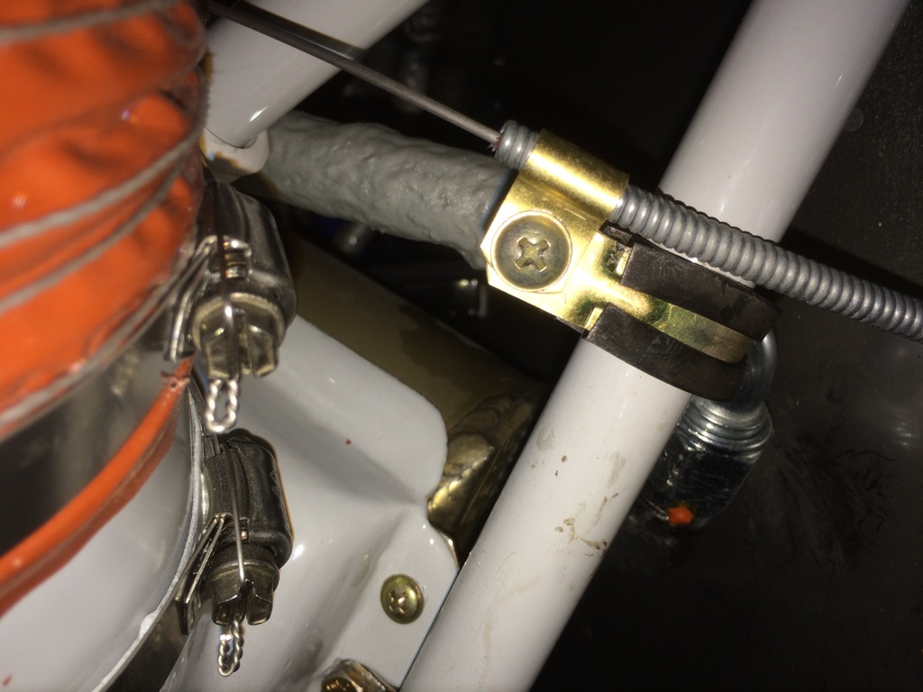
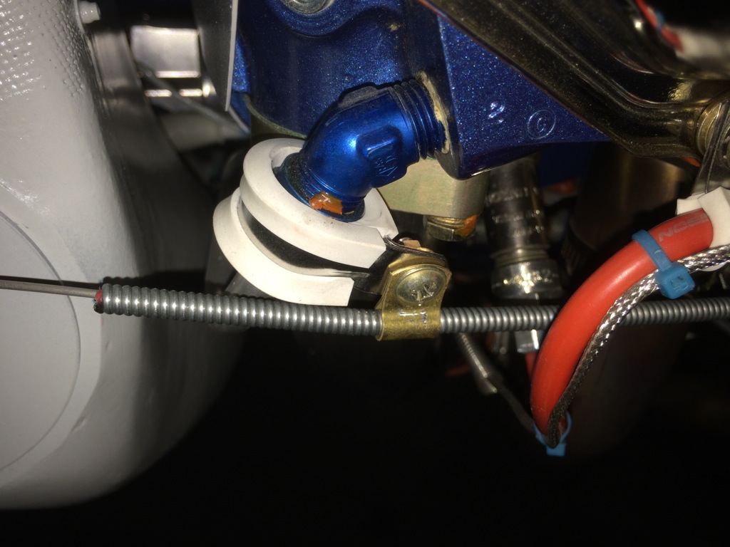
While the battery test was running, I replaced a couple of cable clamps in the engine compartment with non-cushion bowden clamps that hold the cable much more securely than the cushion clamps I was using before.  This is the clamp for the oil cooler butterfly control cable.

I also replaced the cable clamp at the forward end of the alternate air door control cable.

Finally, I decided to pull and clean the fuel filter again.  There was a surprising amount of gunk in the filter.  Most of the volume was some sort of fuzzy material, but there was also a lot of dust and even one small metal particle.  I redid the safety wire and installed it back in the airplane.