Ordered Finishing Kit

I faxed in the order for my finishing kit today since Van’s is raising prices on February 1st.  I intentionally wanted to wait until pretty close to the deadline so that I would end up late in the queue since I won’t be ready for the finishing kit in 8 weeks (the normal lead time).  I’m hoping that the rush of orders will push my delivery out to 12-16 weeks.

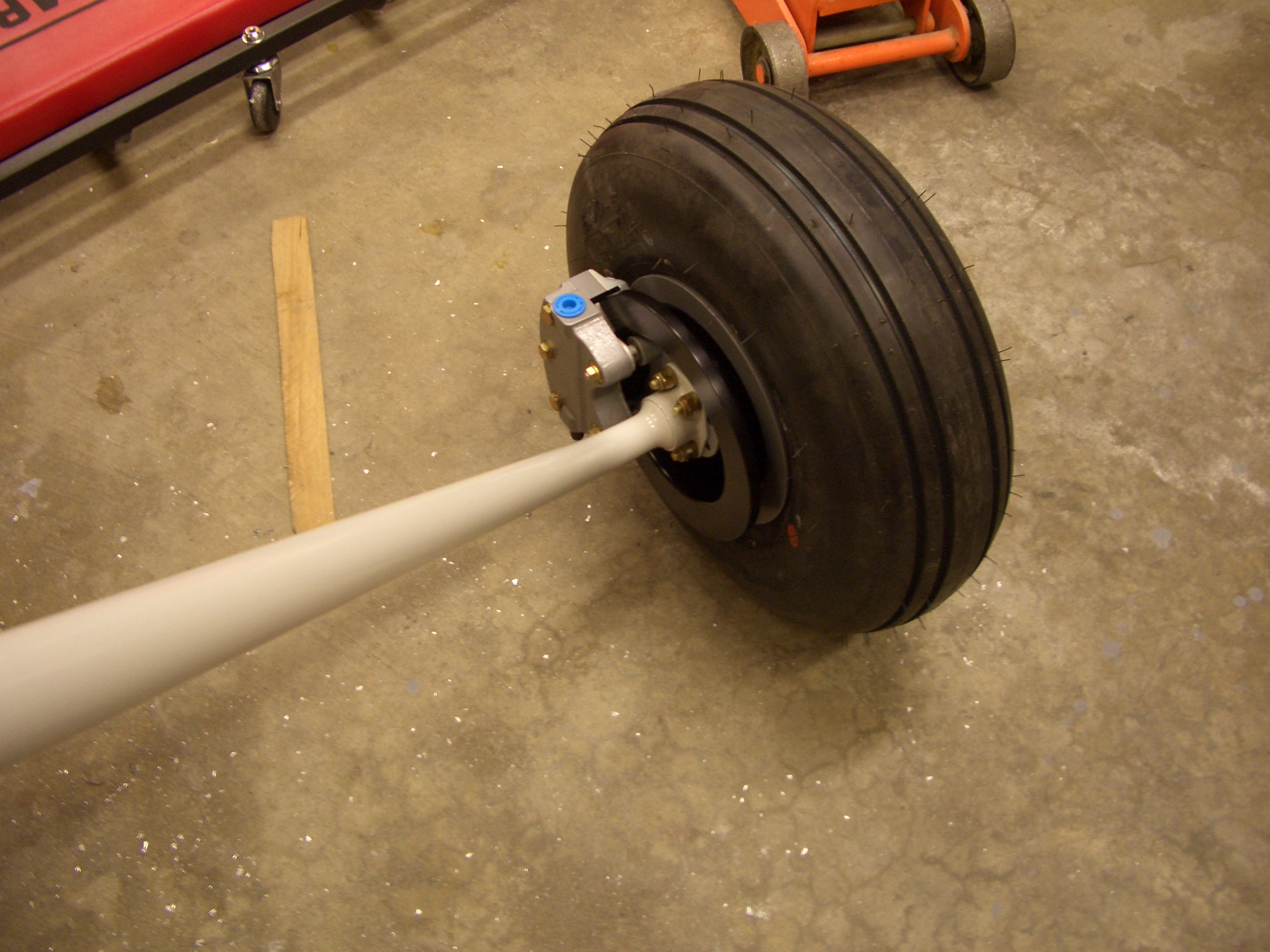
Since I’m going with the AeroSport Power IO-375, I ordered the Dynafocal I engine mount with a cowl for the parallel valve engine with horizontal induction.  Since I’m going with a WhirlWind propeller, I also deleted the spinner.  I will be deleting the wheels and brakes from the finishing kit since I’m upgrading those to Grove units, and I will also be deleting the tires and tubes since many consider them fairly low quality.  I’ll replace them with Condor tires and Michelin AirStop tubes.

Finish Kit Arrived

My finish kit arrived today!  It came via FedEx freight in two days from Van’s.  I took a few pictures to document some minor crate damage in case there was any damage to the contents.

Here was one minor puncture.  Although small, it would have taken a pretty good hit to break through the plywood like this.

The top on the other end had separated from the side, but the metal strapping and some screws had prevented it from opening very much.

When I opened the end with the impact damage, I could see that one of the reinforcing pieces had pulled away from the side.

Once I got the top off, the first thing you see is the canopy and the aft edges of the cowling.  Nothing looks like it moved in transit.

My buddy Andre stopped by and helped me inventory most of the kit and get the crate out of the garage.  Here is the canopy with the engine mount and gear legs under it.  I was surprised at just how light the engine mount is and just how heavy the gear legs are.  The engine mount is constructed of relatively thin walled steel tubing, but the gear legs are roughly 1″ diameter solid steel bars.

Here is the cowling with the two halves roughly fit together.  There will be a lot of work to make these fit together nicely.

Fit Engine Mount and Main Gear

Andre stopped by today and helped me fit the engine mount and main gear.  I used a couple of long Bessey clamps to clamp from the vertical side tubes of the mount to the center section.  I then used a dead blow mallet to adjust the mount until it was evenly spaced all around, then tightened the clamps to prevent the mount from moving.  I used a 3/8″ drill bit and drilled the holes in the firewall.  There are six holes in total, and all pass through beefy structure on the backside of the firewall to transmit the engine loads into the rest of the airframe.

Here is the engine mount all drilled with four of the bolts installed temporarily.  Now that the mount is in place, I marked where the gear legs will interfere with the lower firewall flange.  I used a carbide burr in my die grinder and removed the material that was visible through the landing gear tube.

I slipped the landing gear in the mount and with a little muscling, I got them all the way in so that I could slip an AN5 bolt part way into the hole at the top.  The gear legs have bearing surfaces inside that only touch the engine mount at the top of bottom of the outer tube.  There is a single bolt at the top of the tube that holds the gear legs on.  It doesn’t seem like much, but I’ve never heard of one of these failing, so it must be plenty strong.

The flanges for the two center holes in the engine mount don’t touch the firewall.  This is a pretty common problem since the engine mount can distort slightly during welding.  The fix is simple and requires fabricating little spacers so that the bolts can be tightened without flexing the mount.  These are pretty thin (0.016″ and 0.032″).  I took the mount off, deburred the holes and cleaned up the shavings.  I reinstalled the mount with the proper hardware, but then realized that I don’t have an appropriate torque wrench for these bolts.  These need to be tightened to 160-190 in-lbs, but my smaller torque wrench only goes to 150 in-lbs and my bigger one starts at 20 ft-lbs (240 in-lbs).  I’ll probably use an extension on my smaller torque wrench instead of buying an intermediate torque wrench since these are the only AN6 bolts on the airplane.  My current torque wrenches can torque AN5 (and smaller) as well as AN7 (and larger) bolts.

Finished Finish Kit Inventory

No pictures tonight, but I finished the finish kit inventory and sorted all of the hardware into my storage bins.  No missing items fortunately, and just one backordered item (gear leg fairings).  I got most of the large pieces put away, but I’m still looking for a place to store the canopy until I’m ready for it.  Jenn’s not liking my idea of storing it in our daughter’s room or on our guest bed.

Fit Left Main Gear Leg

I fit the brake flanges to the gear legs.  It was only after I took this picture that I realized the bolt had to come back out to fit the caliper mounting bracket.  This required reaming the holes in the mounting brackets (which were slightly undersize) out to 1/4″ for the 1/4-20 socket head bolts.  I have no idea why these aren’t standard AN hardware.  In fact, the nut looks like something you’d find at the hardware store, but this is what Van’s specifies.

I reamed the caliper holes out with my 1/4″ chucking reamer for the AN4 bolts that hold the caliper mounting bracket to the brake bracket and attached in with some AN4-6A bolts.  I would have used AN4-5A bolts except that I didn’t have any.  The plans specify AN4-11A bolts because these also go through some spacers and the wheel pant mounting bracket.  I’ll do the phase 1 flights without that bracket installed though since it’s prone to cracking without the wheel pant in place, so this will probably be how this stays all the way to first flight.

I lubricated the gear leg with some AeroShell 33MS grease (the only grease I’m using for the entire airplane), and slipped it into place.

I installed the AN5-21A bolts ad torqued them down.  AN5-20A would have been better since I had to use two washers, but I don’t have any.

Finally, I repacked the wheel bearings with fresh AeroShell 33MS grease and mounted the wheel and brake caliper.  Nothing’s been final torqued at this point.

Fit Right Main Gear Leg

I fit the right main gear leg tonight and packed the right wheel bearings.  The tailwheel spring has not been installed yet, so the tail is still sitting on a sawhorse.  The plane is only a few inches taller than it was when the entire fuselage was on sawhorses since I intentionally set them high because of how tall I am.  Access to the inside while leaning over the longerons is still totally fine.  The plane is also much more stable this way.  Although the sawhorses were steel, the legs could move back and forth slightly, so this is a definite improvement.

Plane Is On Its Gear

Jenn helped me suspend the canopy from the rafters so that it’s out of the way and isn’t likely to get bumped.  I used two straps at each end and ran the ropes through some scrap boards so that the ropes wouldn’t try to squeeze the canopy sides inward.

I slipped the tailwheel into the mount and wheeled the plane out into the sun for the first time.

With the plane on the lawn, I spent quite a while cleaning out the garage.  I needed to change the layout so that I’ll have room to install the engine and still close the garage door.  I moved the benches along side the fuselage and cleared a spot along the back wall next to my tool box so that the tailwheel can tuck right up against the wall.  Here is everything back in place.

Started Canopy Hinge

I started working on the canopy hinge mechanism tonight.  First up is to rivet the outer subpanels to the forward ribs using the top two holes with flush rivets on the inside.  This is so the hinge blocks can be mounted flush to the ribs.

I clamped a piece of scrap metal over the small inner riblets to align it with the outer forward ribs.

Worked on Canopy Hinge Blocks

I clamped the C-617 canopy hinge blocks to the forward ribs and marked the forward holes with a #12 bit.  I then took the blocks off and drilled these to #10 on the drill press.

I then clamped the C-617 and C-618 blocks together and transferred the holes.