Installed SkyView EMS and Lightspeed Ignition Box

I installed some one leg nutplates on the SkyView EMS box because I need to install the screws from the other side in case this box ever needs to come out.

I then installed the EMS on the outboard side of the subpanel support rib.  You can see here why I needed to install the screws from the other side.  The top skin curves down here, so there would be no room to get a screwdriver on these screws if they were installed from this side..

I also installed nutplates on this side to attach the Lightspeed ignition box.

Here’s the Lightspeed ignition box.  You can see the screws that attach the EMS just above this box.  There is another pair just below the ignition box.  These are all reachable without removing the ignition box.  There is just enough room in front of the ignition box for the RG-400 wires to curve downward to run along the top firewall stiffener without contacting the firewall.

Installed Vertical Power VP-X Pro

I didn’t like the strain put on the ignition wires by the tight bend necessary to curve down toward the top firewall stiffener, so I picked up a couple of right angle BNC adaptors from Fry’s.  These were only a few bucks each vs. the $17 each (plus shipping) for right angle crimp connectors.  This creates an extra connection in each line, but they’re on quite solid, so I’m not worried about it.

I received my Vertical Power VP-X empty shell today.  Instead of using the included mounting brackets, I cut a couple of pieces of 0.063″ angle so that the VP-X could be mounted to the bottom of the two subpanel ribs.  This location will create plenty of room on each end for the connections.  It’s high enough that it won’t interfere with the control cables, but low enough (and forward enough), that it shouldn’t interfere with any radios that poke through the subpanel.  The forward mounting angle is 1 7/8″ aft of the top firewall stiffener, which provides plenty of clearance for the parking brake valve arm.  You can also see in this picture that the ignition wires fall naturally along the forward mounting angle (now that the right angle adaptors have been installed).  I’m likely going to use that angle as an anchor point for a forward wiring bundle.

I drilled and attached the mounting angles to the VP-X.

After cutting the angles to length and drilling them to the subpanel ribs, I installed nutplates on the ribs and reinstalled the VP-X.

Here you can see the nutplates that are used to anchor the mounting angles.  This is *very* strong.  The actual VP-X (as opposed to the empty shell) weights 2lbs.  There might be as much as a pound or two of other stuff hanging off these mounting angles.  Even at 6 Gs, that’s no more than 25lbs or so.  This can easily hold twice that, so there is plenty of margin built into this.

Demo Seats and Wire Routing

I’m having my interior done by Classic Aero Designs.  I really want to go with the Aviator seats, but I had some concerns about the amount of headroom I’d have.  I spoke with Luke at Classic Aero and he offered to send me out both an Aviator and a Sportsman seat so I could try them out.

The Aviator seat has a rounded top and an integral frame.  It’s also offered with a headrest and looks much more like an automotive seat.

Since it has an integral frame, the back is covered and has a pocket.  There is also an adjustable lumbar support.

The Sportsman seat has a square top (because it uses the Van’s seat back which has a square top).

It also has an adjustable lumbar support, but the back must be un-velcroed from the frame to adjust it.

I installed a couple of nutplates on the B&C voltage regulator and installed it to the right subpanel rib.

There are two bundles of wires on each side of the VP-X that need support.  I also need a way to route wires between the left and right side of the aircraft.  I installed some adel clamps on the bottom of each subpanel rib.  They’re just clecoed on since I’m sure I’ll have to swap them out for different sizes after I know how many wires will run through each clamp.

It’s not clear from this picture, but they’re aligned with each set of connectors on the VP-X.

I also installed a couple of adel clamps on the forward VP-X support angle.  Wires that need to cross from one side of the plane to the other will step up and cross on to of the VP-X through these adel clamps.

Here you can see that the ignition wires cross over the VP-X, down through the forward adel clamp below the subpanel rib and then out through the firewall pass-through.  Once these are zip-tied to all the other wires running along side them, these will very well supported.

EMS and Ignition Wiring

I removed all of the unused wires from DB-37 connector on the SkyView EMS.  I ended up taking out a couple more after this picture was taken.  This was a surprising amount of weight that I don’t have to haul around without benefit.

Here’s the remaining wires.  I’m only using about half the pins in this connector now.  Part of the reason is that all of the position sensors (aileron trim, elevator trim, and flaps) now connect to the VP-X.

I noticed that one of the BNC connectors on the Light Speed ignition box was loose.  I probably violated the warranty (which is likely expired now anyway), but I popped the cover off to tighten it up.

Here’s the connector in question.  You can clearly see that the lock washer isn’t even compressed.  They simply forgot to tighten it fully at the factory.

By comparison, the other BNC connector was tightened fully.  Now they both look like this and are rock solid.

I decided to reroute the ignition sensor wire so that it takes a more direct route back toward the firewall.  This also keeps the wire away from the snorkel (not yet installed).

The wire follows the starter wire back to the engine mount then will get anchored where my finger is so that it will not interfere with the oil cooler.

It then turns up and follows the CHT/EGT wires through the firewall.  It was a pain getting the connector through the pass-through.  I had to remove most of the other wires as well as the connector housing to squeeze it through.

From there, it follows the manifold pressure back and through the aft adel clamp.

Both then turned upward and connected to the Light Speed ignition box.  You can also see a red and black wire running through the right adel clamp.  These are the wires from pins 1 and 3 of the EMS.  The red wire connects to the battery bus and the black wire connects to the firewall ground block.  Together, they’re used to measure battery voltage as well as provide a small amount of power to a couple of the engine sensors.

Both wires run along side the ignition wires.  The black wire then separates here and connects to the ground block.  You can also see that I connected the two VP-X ground wires to their appropriate pins on the J10 and J12 connectors.  These are 18AWG (vs the 22AWG from the EMS) since they carry power for the flap and trim motors which can draw several amps.

The red wire continues on through the front adel clamp and connects to the battery bus.

The label maker I’m using can print on heat shrink tubing.  I’m using that to label certain wires.  All ground wires in the plane will be black, so there’s no need to label them.  All power wires will be labeled as well as both ends of signal wires.

Received More Goodies from Dynon

I got my transponder from Dynon.  I purchased the high-power, class 1 SV-XPNDR-261.  This thing is nice and tiny, but still puts out 250W of transmit power.  It also meets the full ADS-B out requirement when connected to a TSO-C146A GPS (such as the Garmin GTN series that I’m going with).  It also displays TIS traffic on the SkyView which is handy around the areas I fly in.

I also received the ARINC-429 module.  This lets the SkyView interface fully with the Garmin GTN unit to get features like GPS steering for the autopilot, CDI autoscaling, and vertical guidance for approaches.

I also purchased a second SkyView Display Harness.  I decided to purchase this separately so I can hold off on purchasing the second display until just before flight.  I can move my single display between sides on the panel when building the overall harness.  You can also see that I purchased a second panel mount USB cable.

I also received a second battery for the right display.  I can go ahead and mount this and connect it to the right display harness.

I also picked up two 30′ network cables.  I’ll cut these up to the custom lengths I need when connecting components.

I also picked up a hobbs meter from Aircraft Spruce.  Although the SkyView has a hobbs built in, I don’t like the idea of having the only record of aircraft flight time being stored electronically.  If there is a failure or I have to send a display back for service, there is always the possibility that the total flight time is lost.

Installed Transponder and Wired Engine Sensors

The Dynon transponder uses a TNC connector instead of an BNC connector.  Fortunately, Fry’s carries RG-58 TNC crimp on connectors.  I’m using RG-400 which uses the same connectors.  I crimped it on to the end of a piece of RG-400.  I’ll cut it to length and put a BNC connector on the other end to connect to the antenna.

I was originally thinking I’d install the transponder and antenna under the passenger seat, but Dynon recommends at least 3′ of separation between the transponder and COM antennas.  Instead, I decided to mount the transponder behind the baggage wall underneath the pitch servo.  The transponder clips to a mounting bracket that is screwed to the center rib just in front of the shelf where I’ll mount the ELT.

Now that the EMS is in its final position, I cut the oil and fuel pressure lines and added crimp ring terminals.

I also crimped the connectors on the manifold pressure sensor wires and installed it in the MAP sensor.

Lastly, I installed the sensor wire on the oil temperature sensor.

I played around with routing the shunt and fuel flow sensor wires over to the right side of the engine.  I decided to have them follow the Light Speed ignition sensor wire to where it mates up with the starter wire, then turn and follow that across the engine compartment.

Here you can see those wires follow the starter cable over to the connector.

They then jump over to the alternator feed wire.  The shunt wires separate there and will connect to the shunt just behind the left tube here.  The fuel flow wires follow the alternator feed wire forward to where the fuel flow sensor will be mounted.

Misc Avionics Stuff

I opened the new SkyView Display Harness and installed the panel mount USB cable.

While looking at the wiring diagram for the transponder, I noticed that there were a couple of loopbacks, so I installed these using some 22AWG wire.

I also got an order from Van’s that included this pressure switch.  I installed it in the right port of the manifold using an AN915-1 elbow.  This will drive both the hobbs meter (connected to the NO pin) as well as one of the annunciator lights to indicate low oil pressure.

I went ahead and installed a wire to the ground pin.  Since I don’t have a ground block on the firewall side, I ran this through the pass through so I can connect it to the ground block on the cabin side.

I decided to go ahead and label the ground wires.  The labels are facing downward since I’ll only be able to see this from below once the last skin goes on.

I have no idea why I didn’t think of this before.  Since I have a label maker that will print on heat shrink tubing, I printed up some labels for my drill bits.  Trying to read these numbers on the bits themselves has become quite a pain.  You can also see that I put the screw/bolt size on the label as well so I don’t have to look these up on a drill guide.

I installed the ARINC-429 module on the front side of the subpanel on the pilot’s side.

I installed the backup battery for the left display on the back side of the subpanel.  Batteries have to be replaced from time to time, so I wanted these to be fairly easy to access.  With the tipup canopy open, these are easily accessible.

I also put a new terminal on the battery positive cable with a 12AWG wire for the battery bus.

I also installed a couple of adel clamps to tie the battery positive cable to the engine mount.  Without this, the terminals would have to carry all of the weight of this cable (and it can weight quite a bit when I’m pulling 6Gs).

The battery bus cable comes through the pass-through and will connect to the battery bus via the bolt on the bottom.

Installed Fuel Flow Sensor and Worked on EGT/CHT Wiring

I removed the fast-on tabs from the wires on the fuel flow sensor and installed some knife connectors.

I then installed the short fuel line between the fuel servo and the fuel flow sensor.  If you want to duplicate my setup, you’ll need a 2.75″ seat-to-seat hose with 1/4″ straight-to-straight connectors and firesleeve.

The output side of the sensor has an identical fuel line, but 9.75″ seat-to-seat.  It’s a little hard to tell from this picture, but there’s quite a lot of clearance all around the sensor.  It’s only about 3″ from the #1 exhaust pipe though.  The alternator wire is a little closer even.  I’ll put a long heat shield along this section of the exhaust pipe to reduce radiated heat to these components.

Here you can see how the fuel hose makes a straight run up to the spider from there.

I then reinstalled the inter-cylinder baffle retaining clamp (which was a pain in the ass).

I’m also using the knife connectors to connect the EGT/CHT wires to the EMS harness.  I got through part of the connectors on the right side tonight.

Here’s a closeup of the #1 and #3 EGT connections.

The knife connectors interlock and form a connection that can’t vibrate apart even under tension.  I’ll put sections of heat shrink over all of these connections before finishing off the wiring bundle.

EGT/CHT Wiring and Firewall Conduit

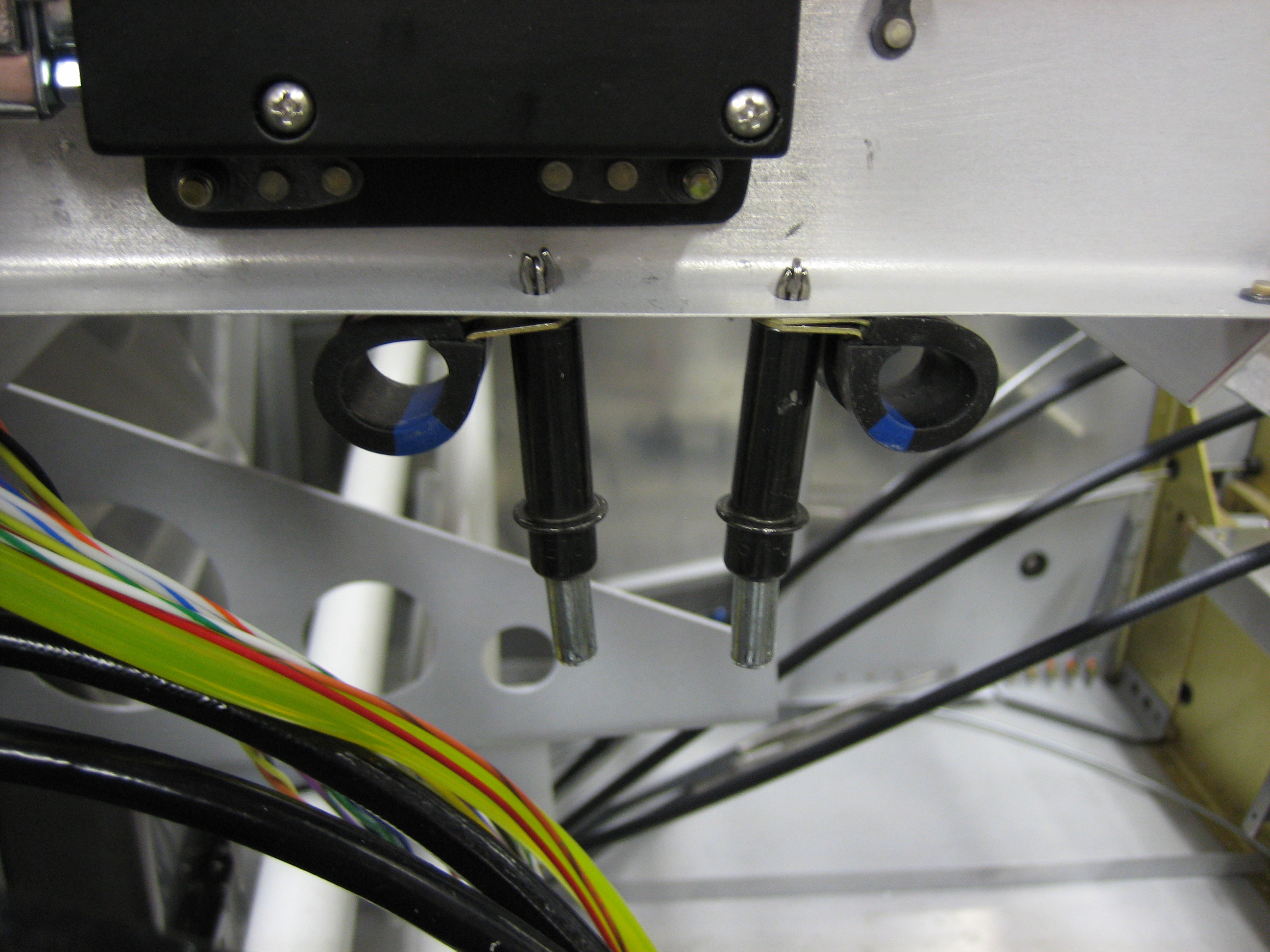
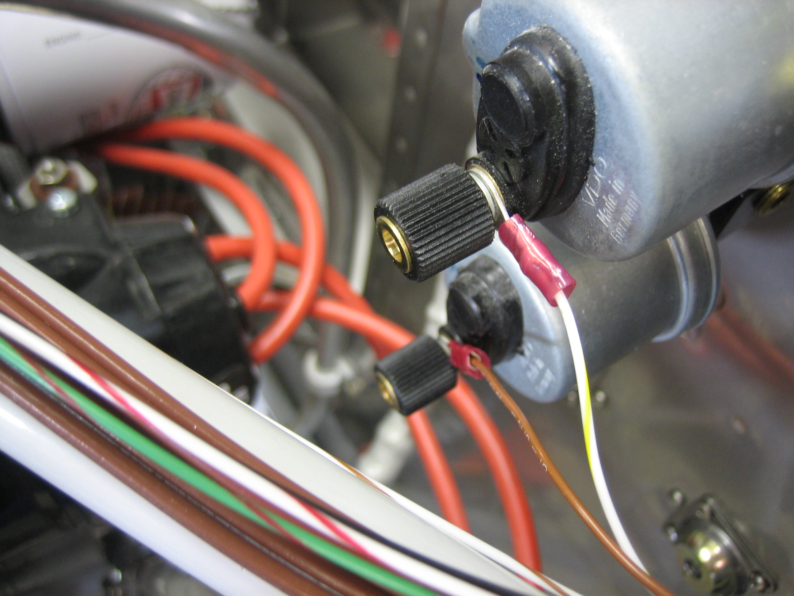
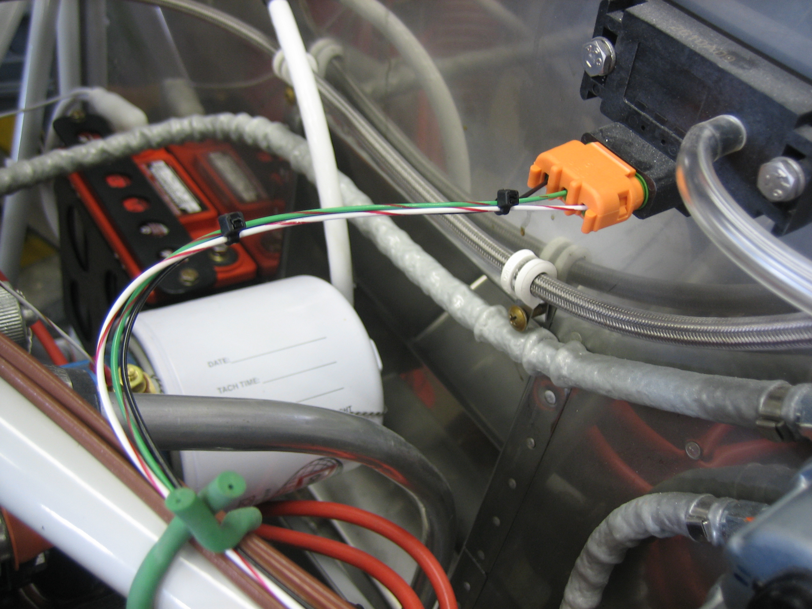
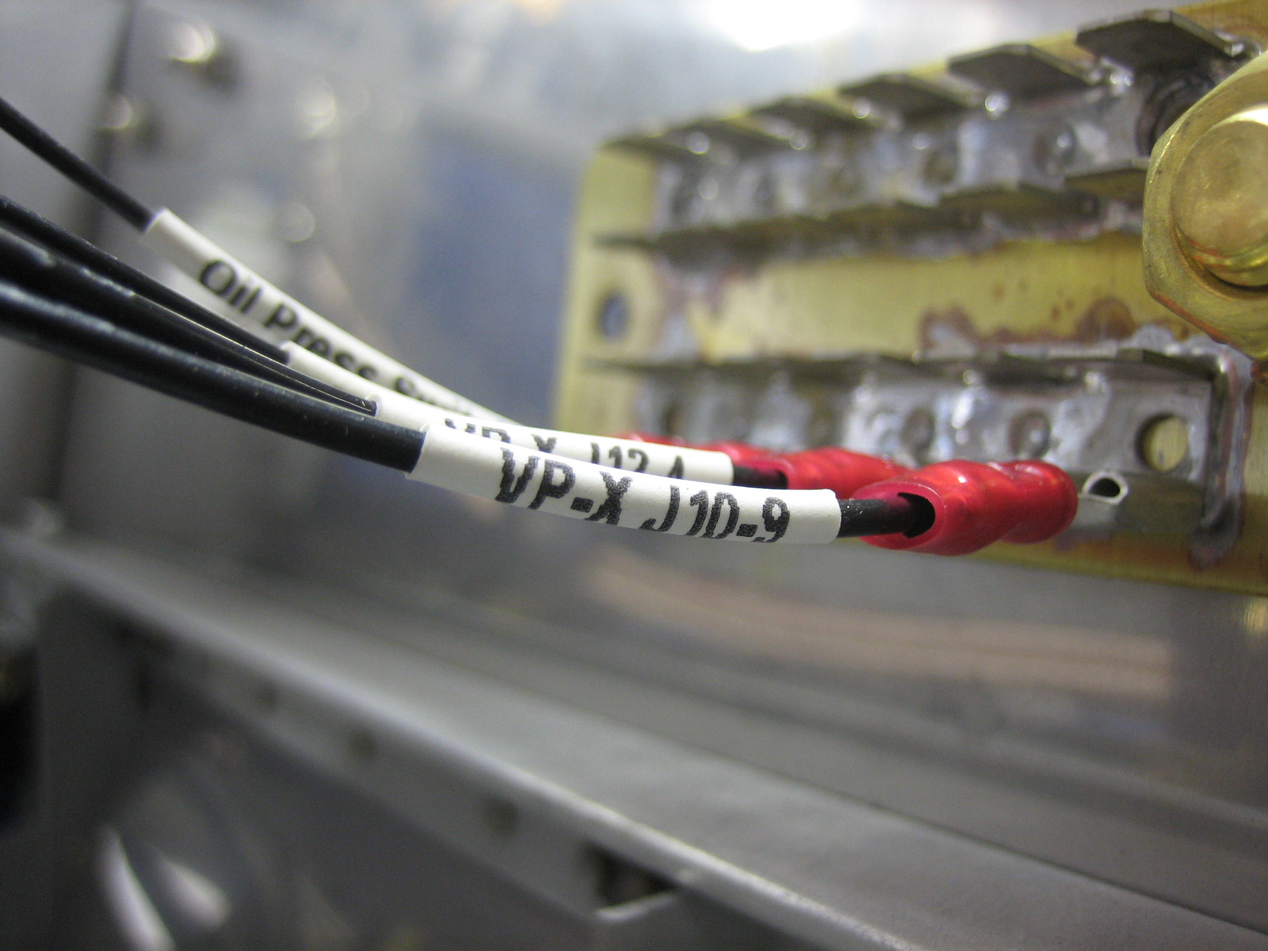
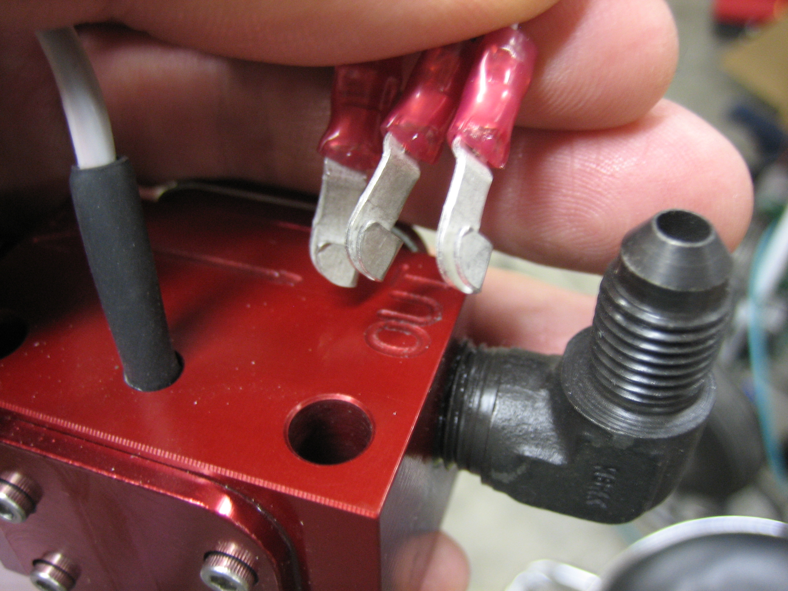
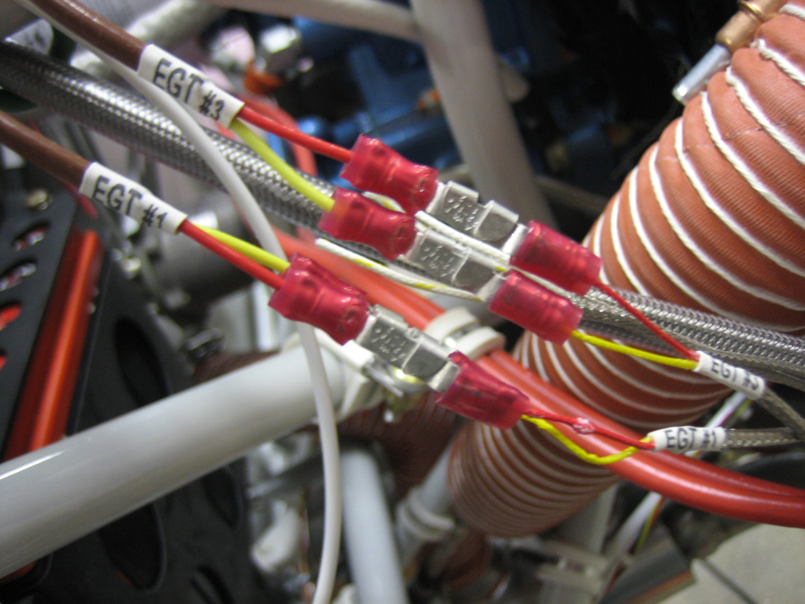
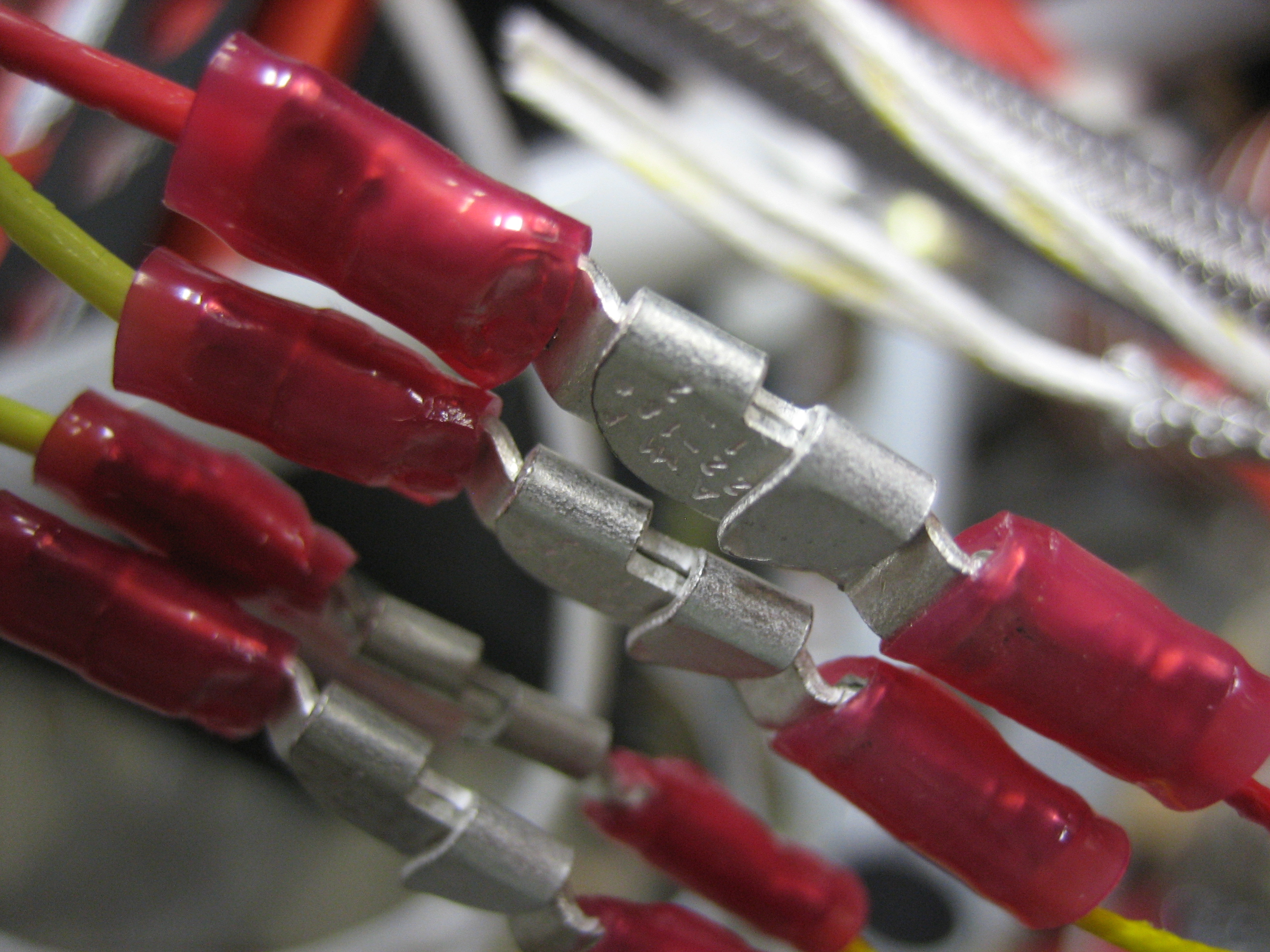
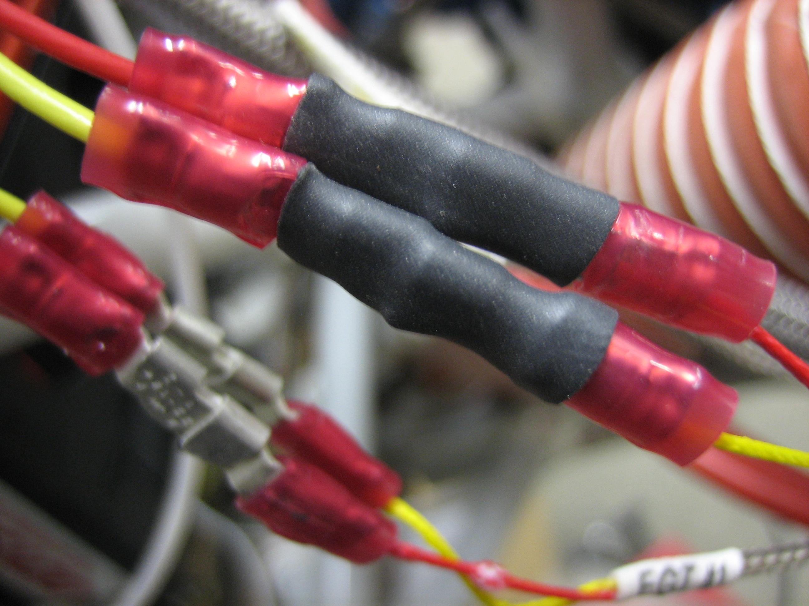
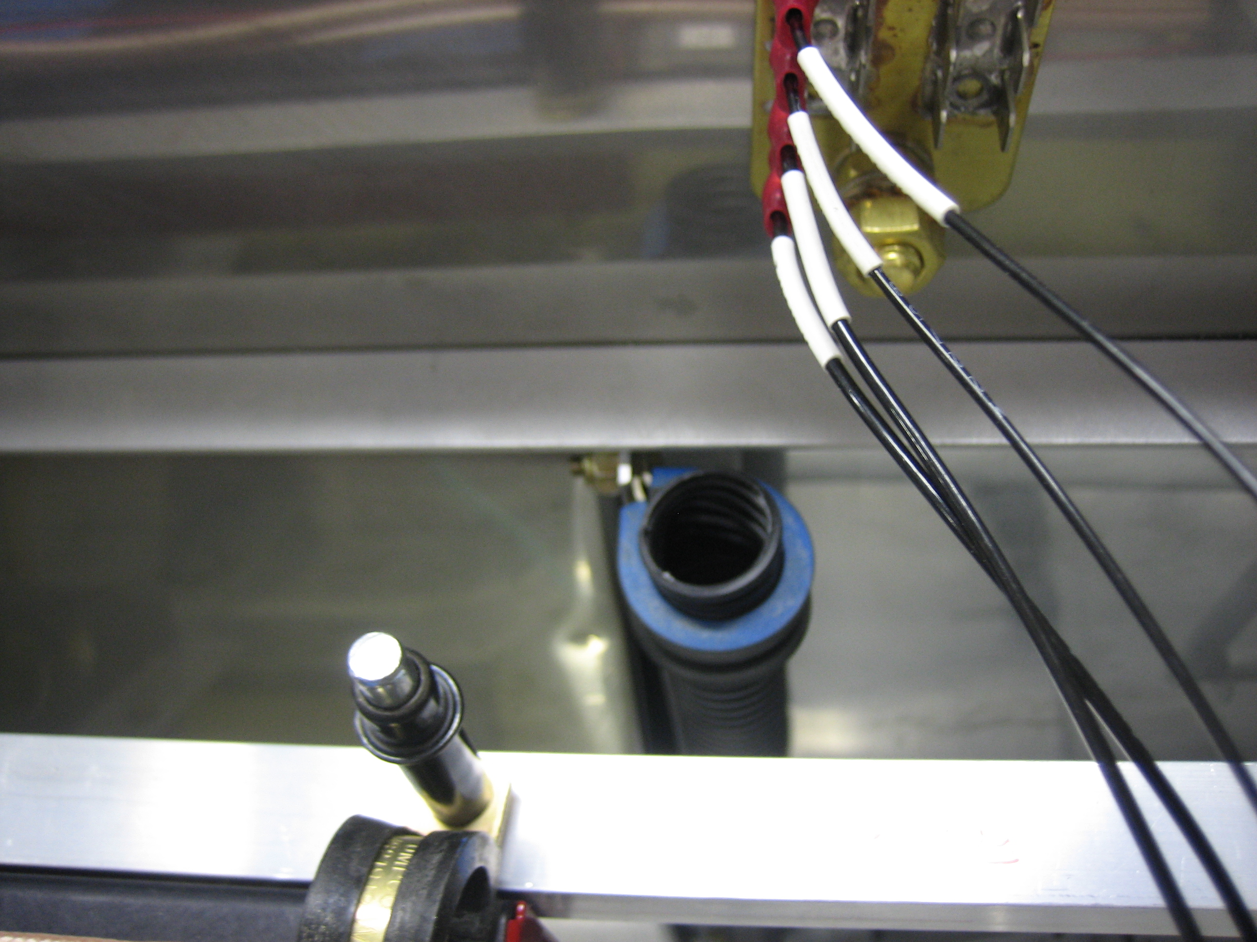
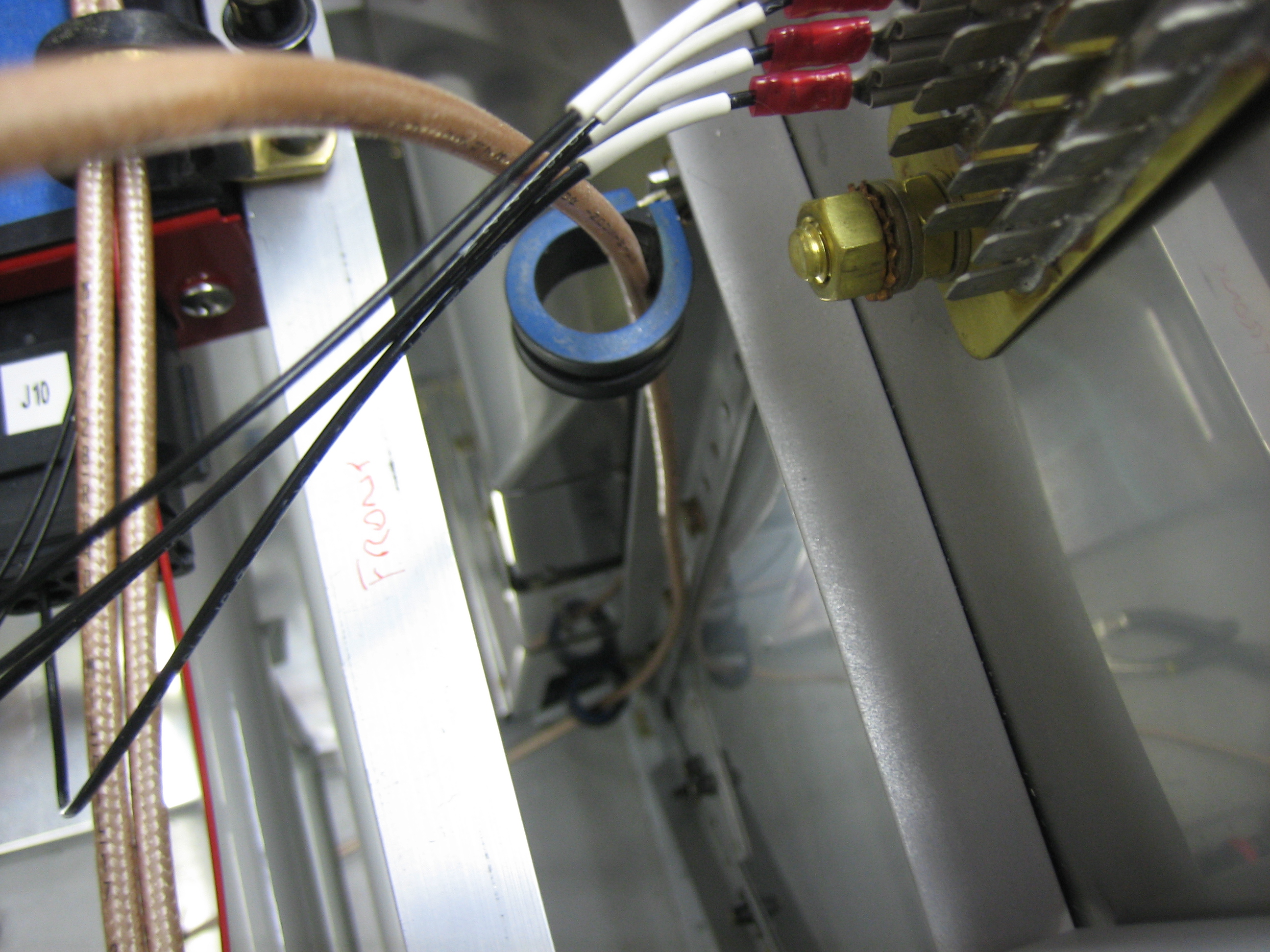
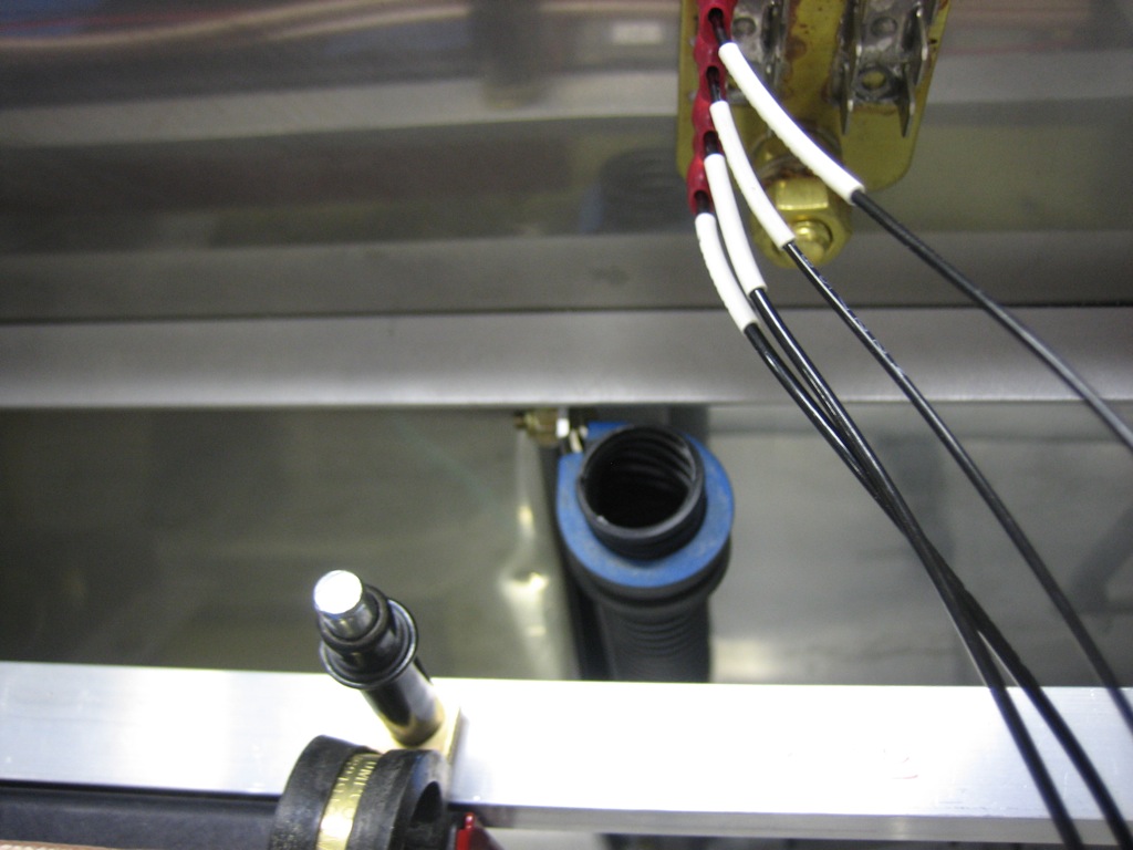
Since the knife splices aren’t insulated where they connect, I slipped a piece of heat shrink over each connection.

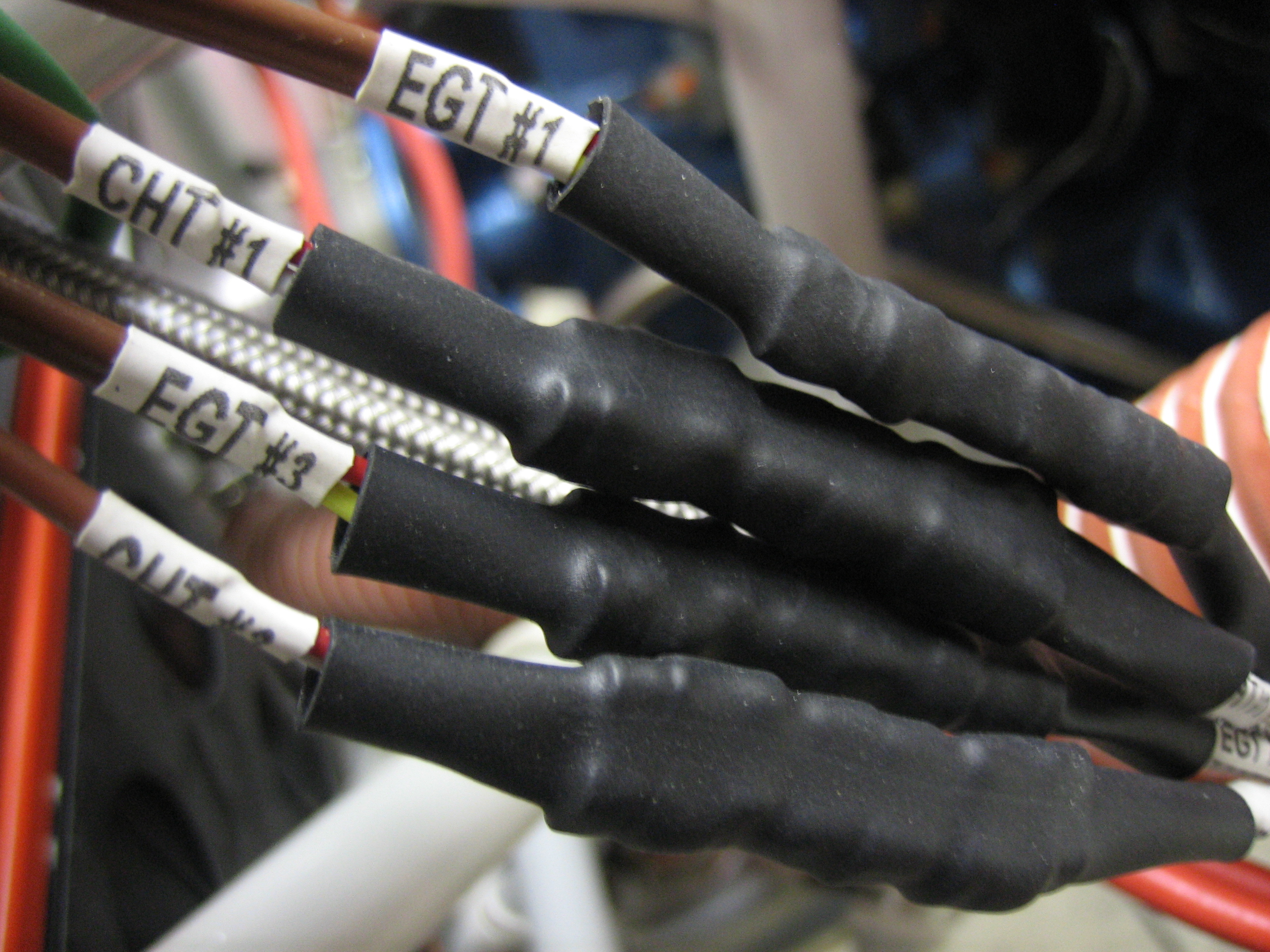
I then put larger pieces of heat shrink over each pair to keep everything immobilized.  For some reason, the EGT probe wires are solid conductors instead of stranded like every other wire used on aircraft, so they need to be well supported.

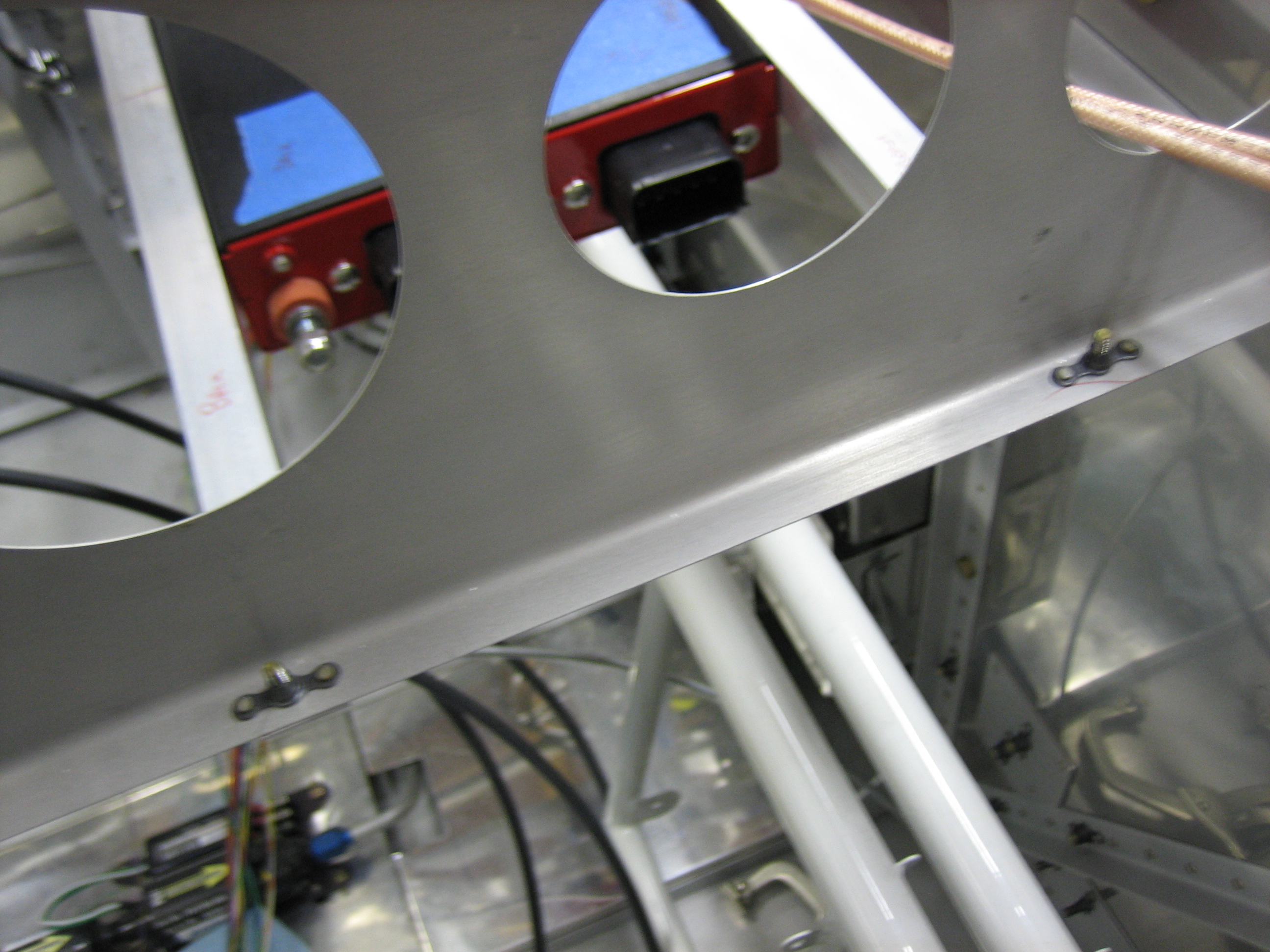
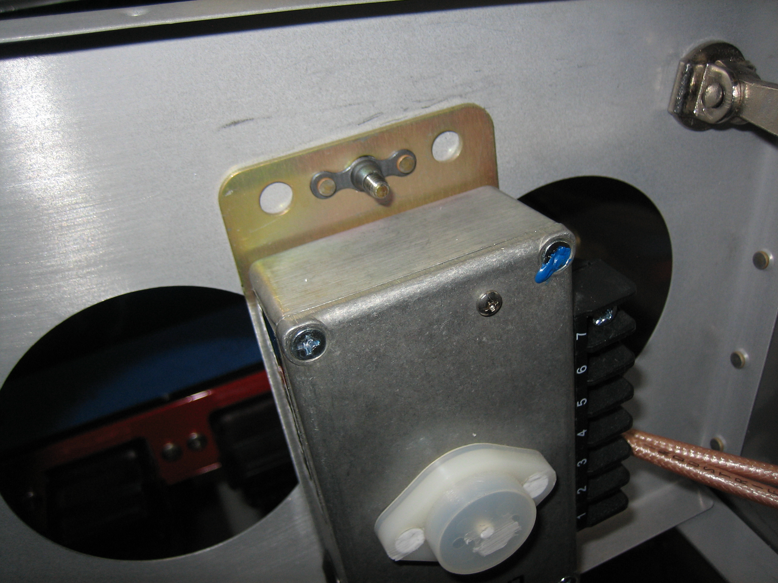
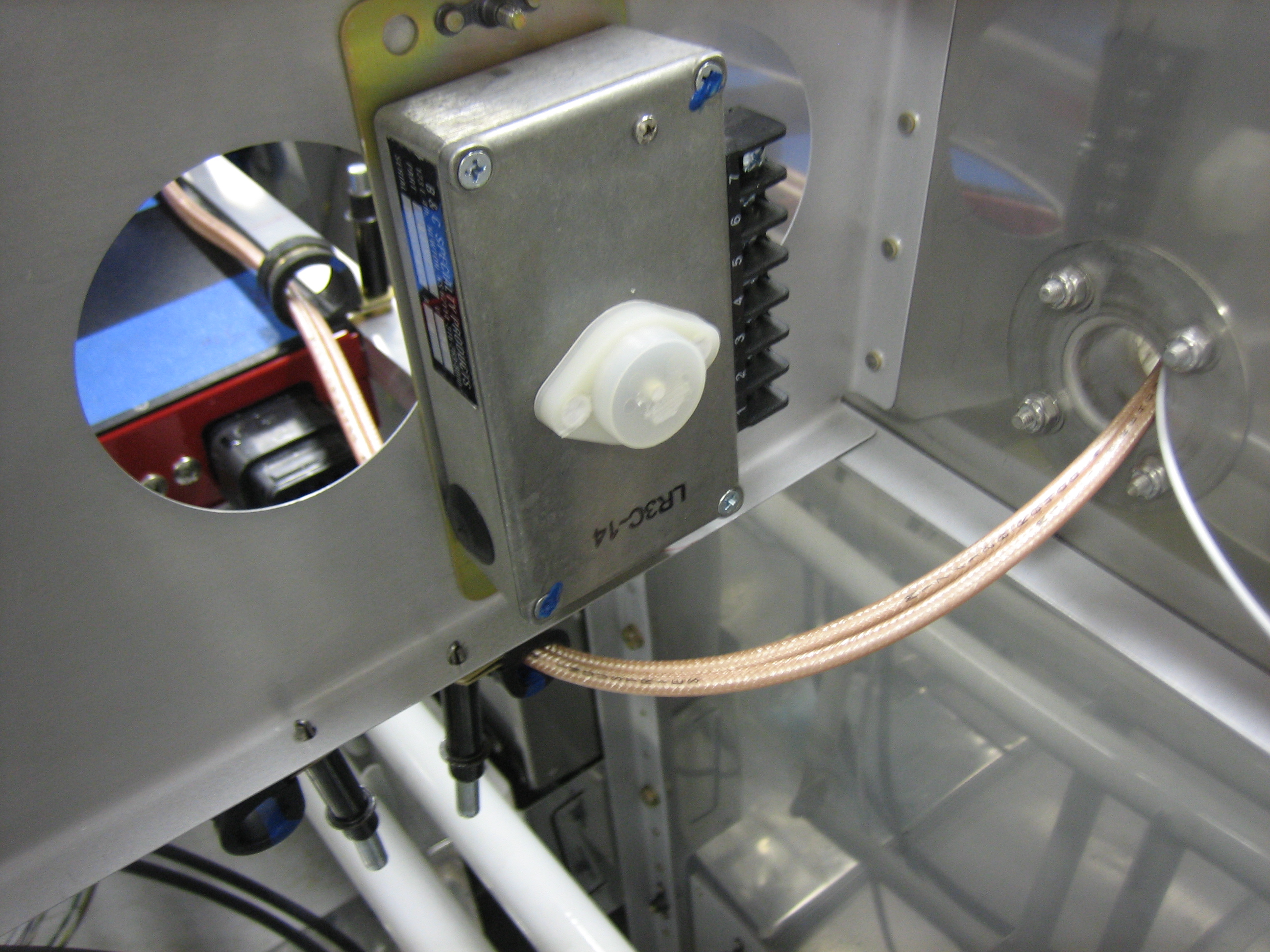
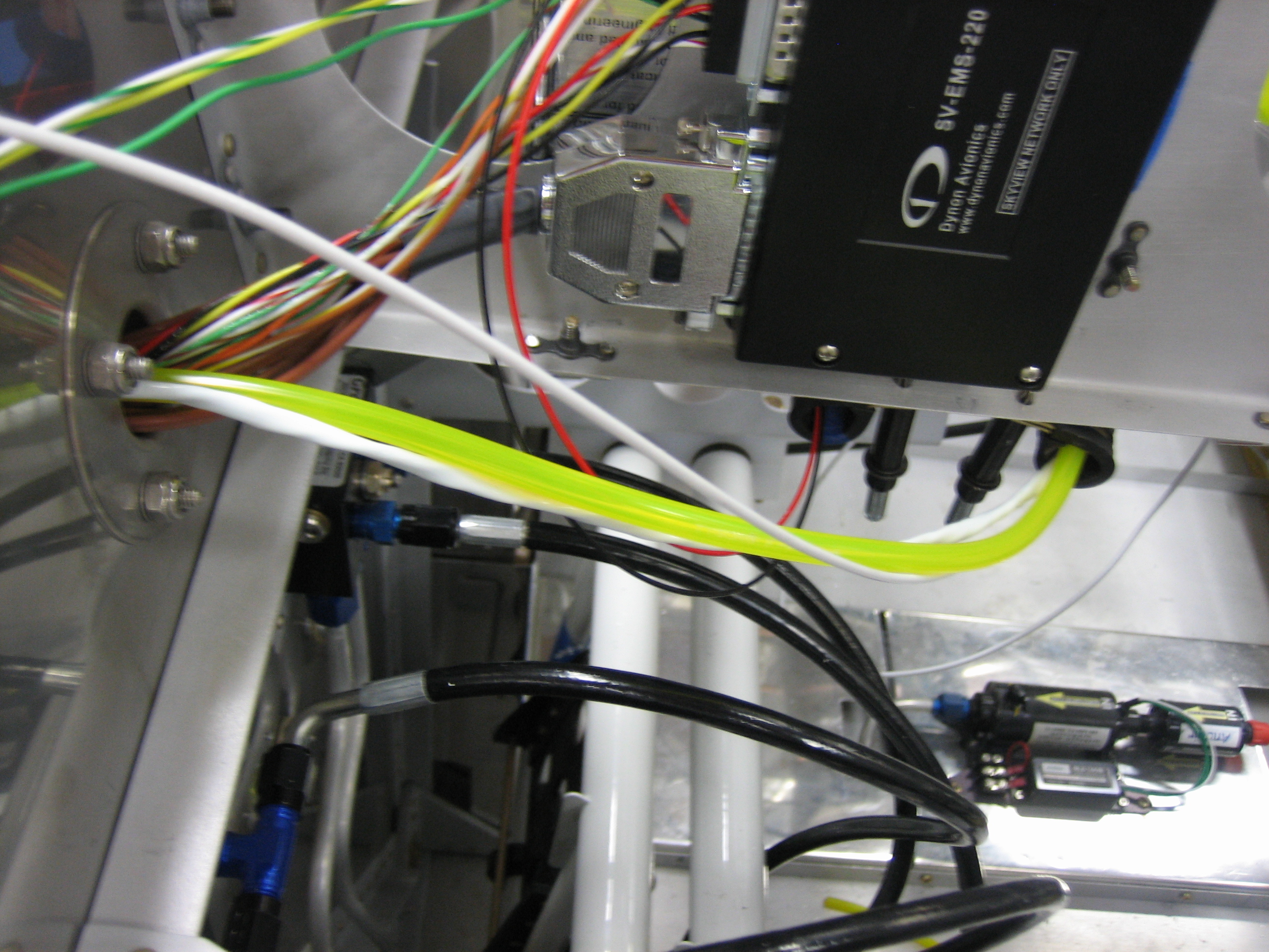
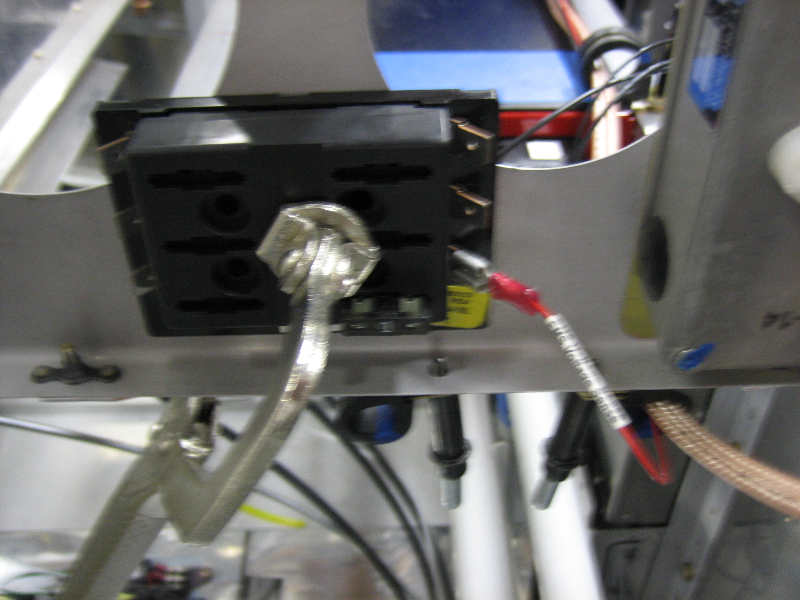
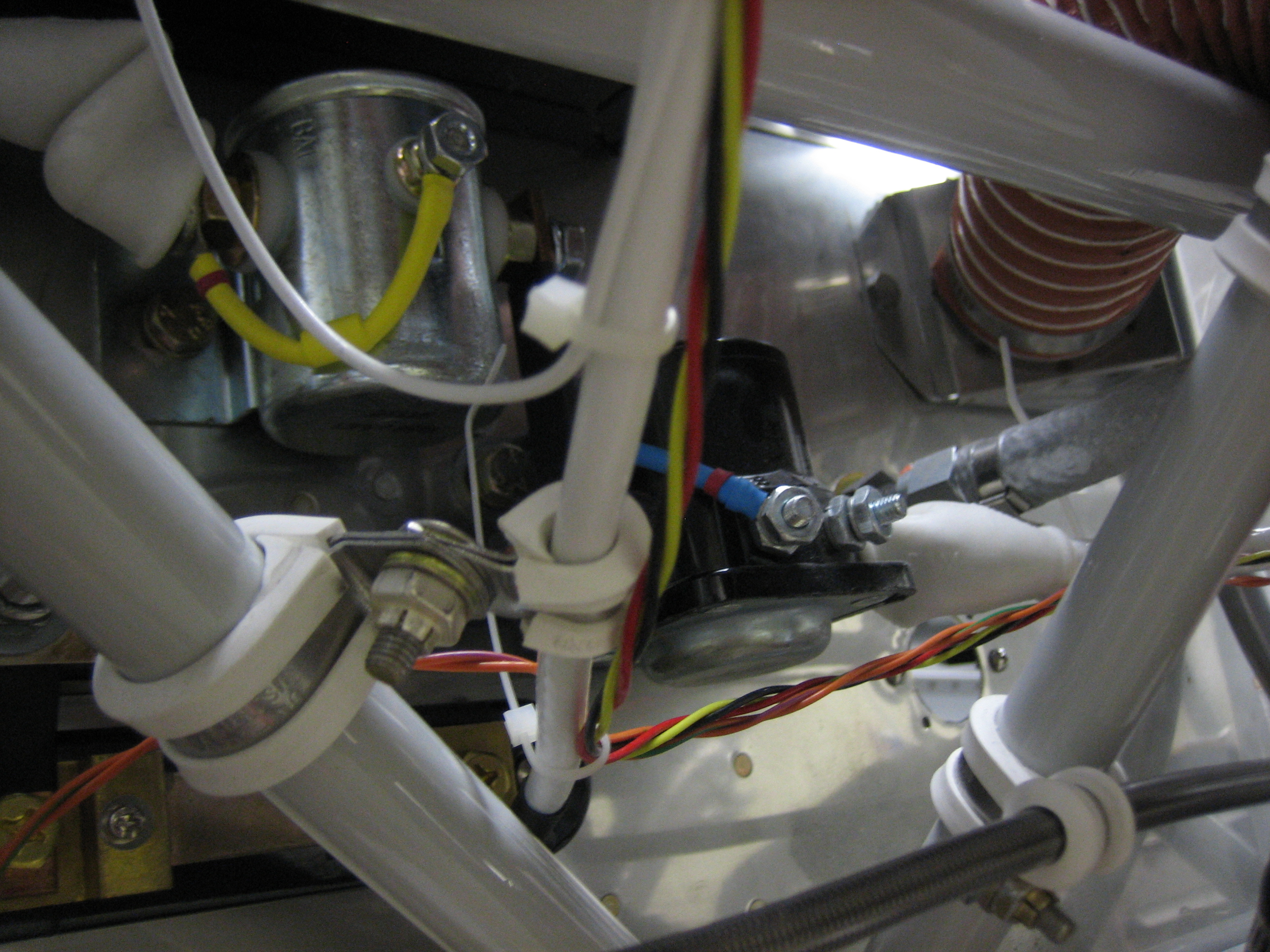
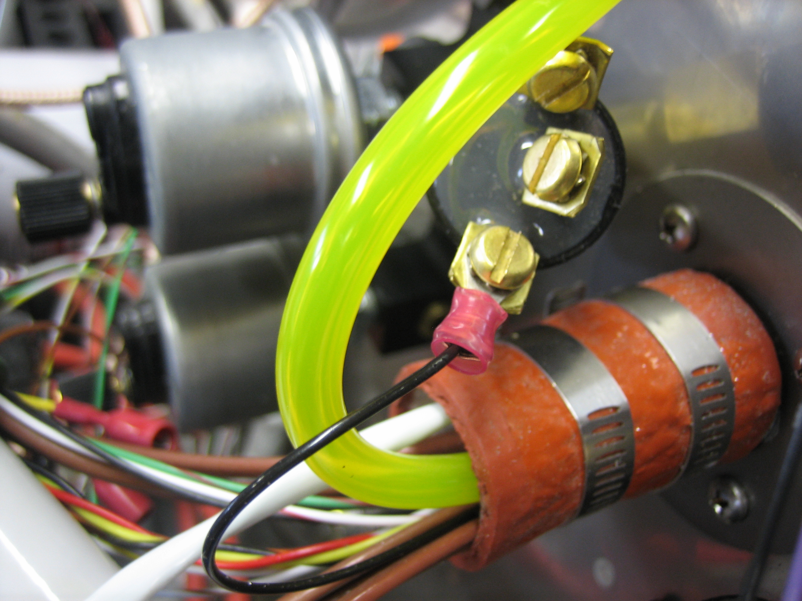
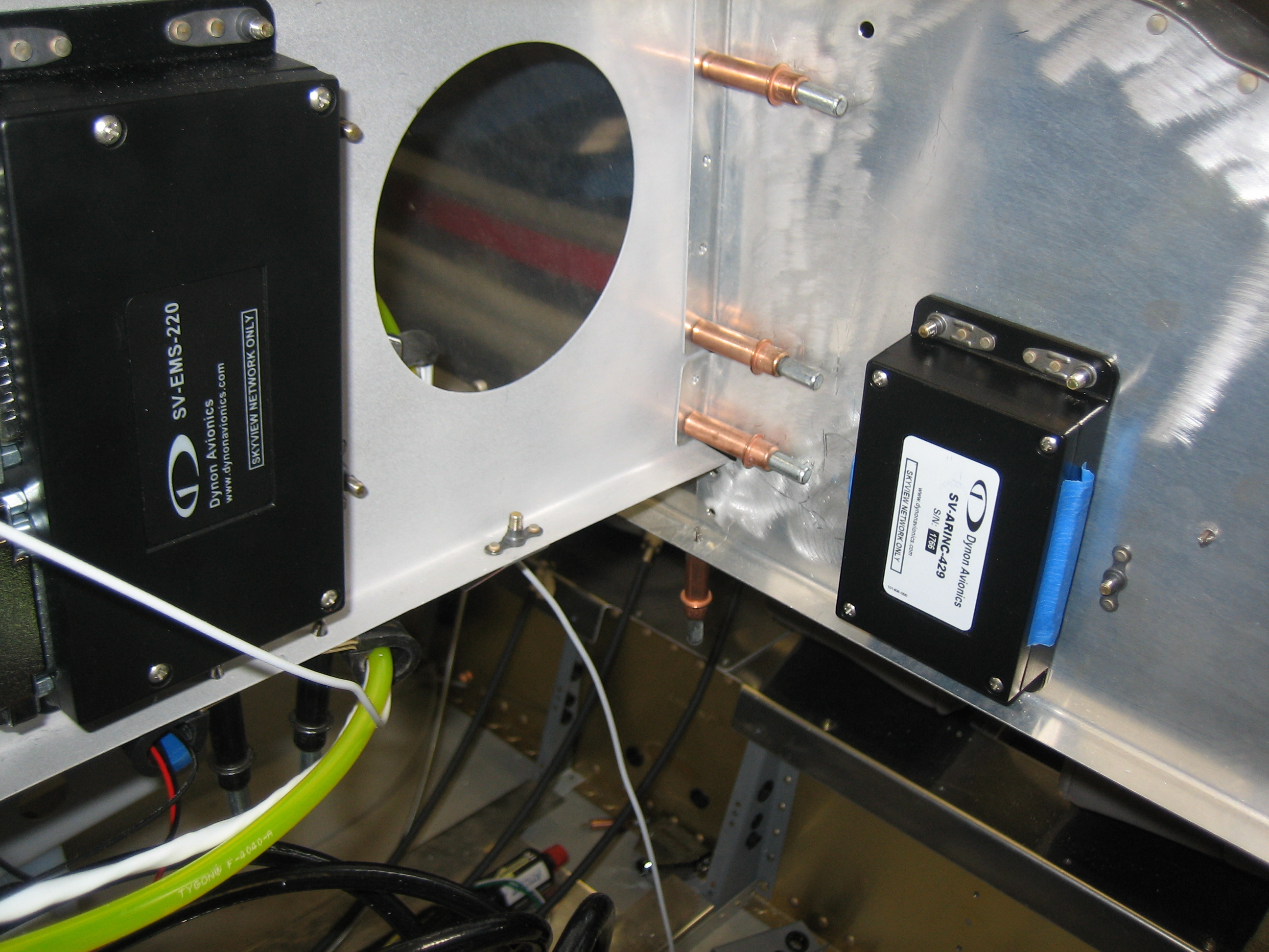
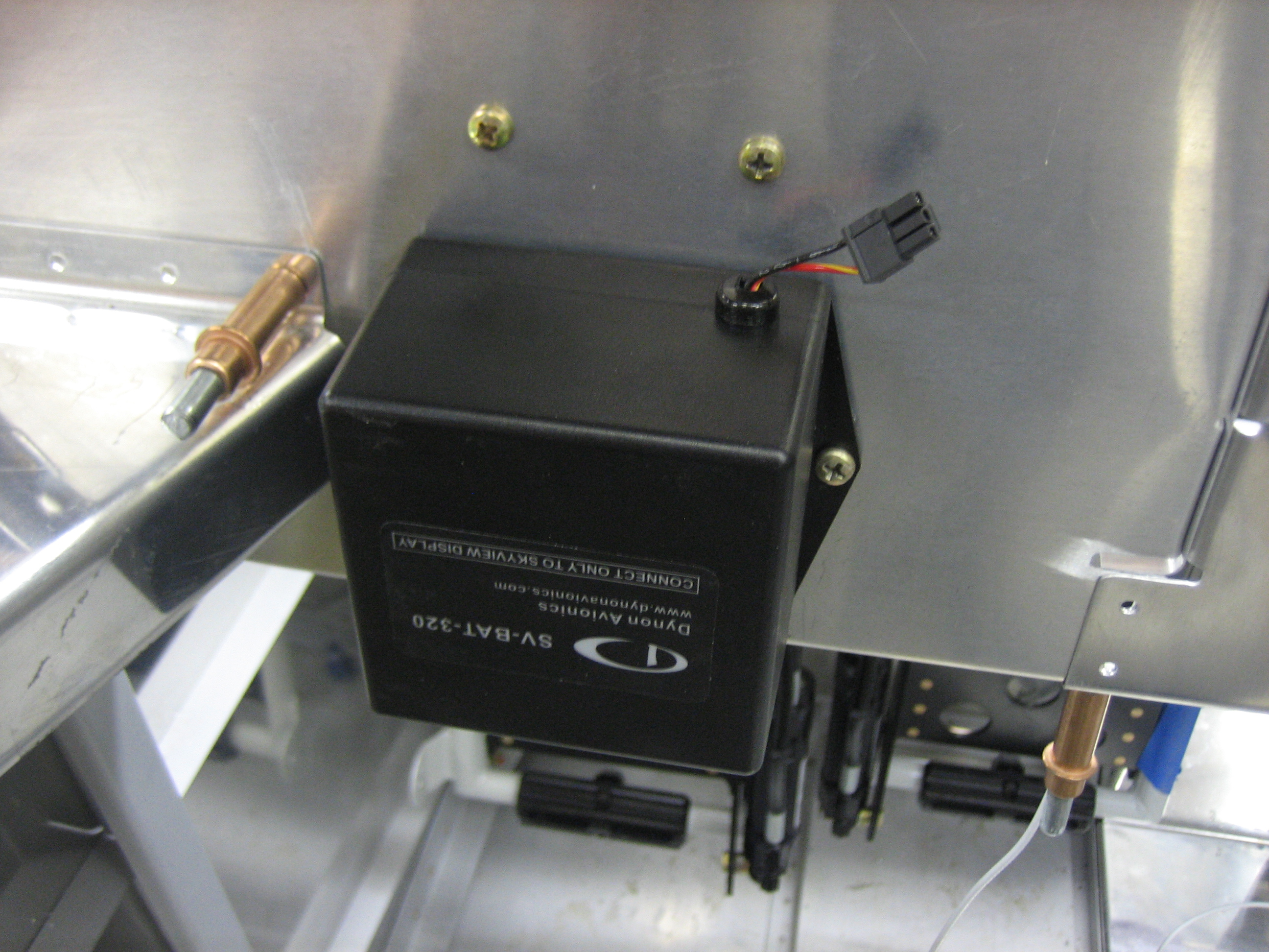
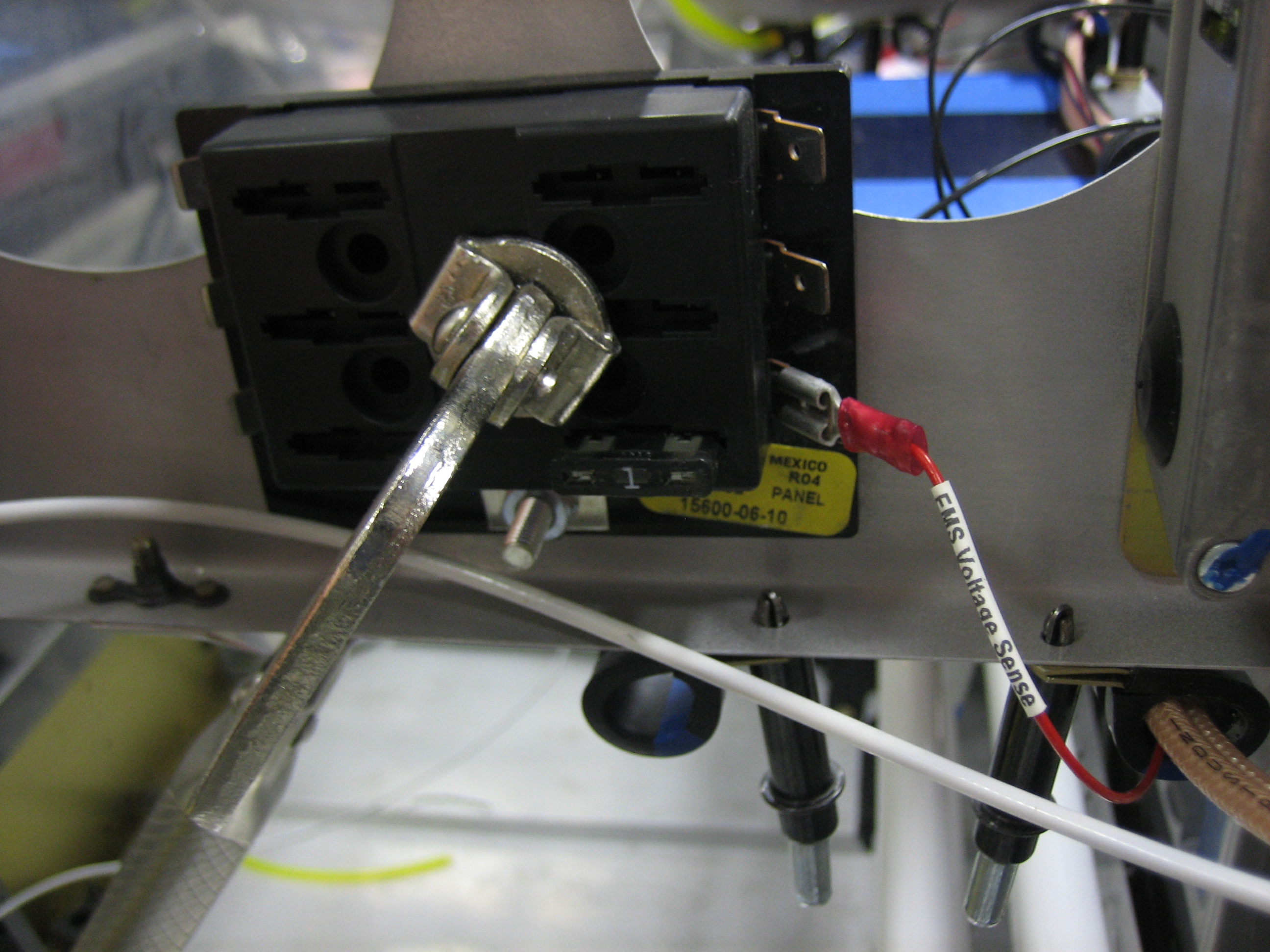
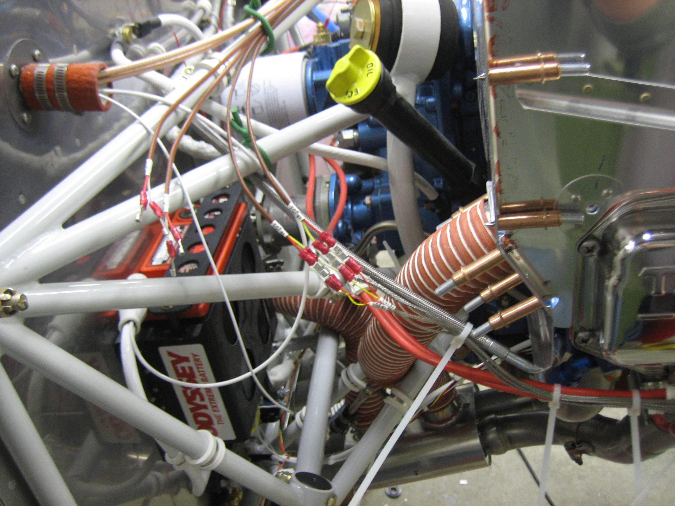
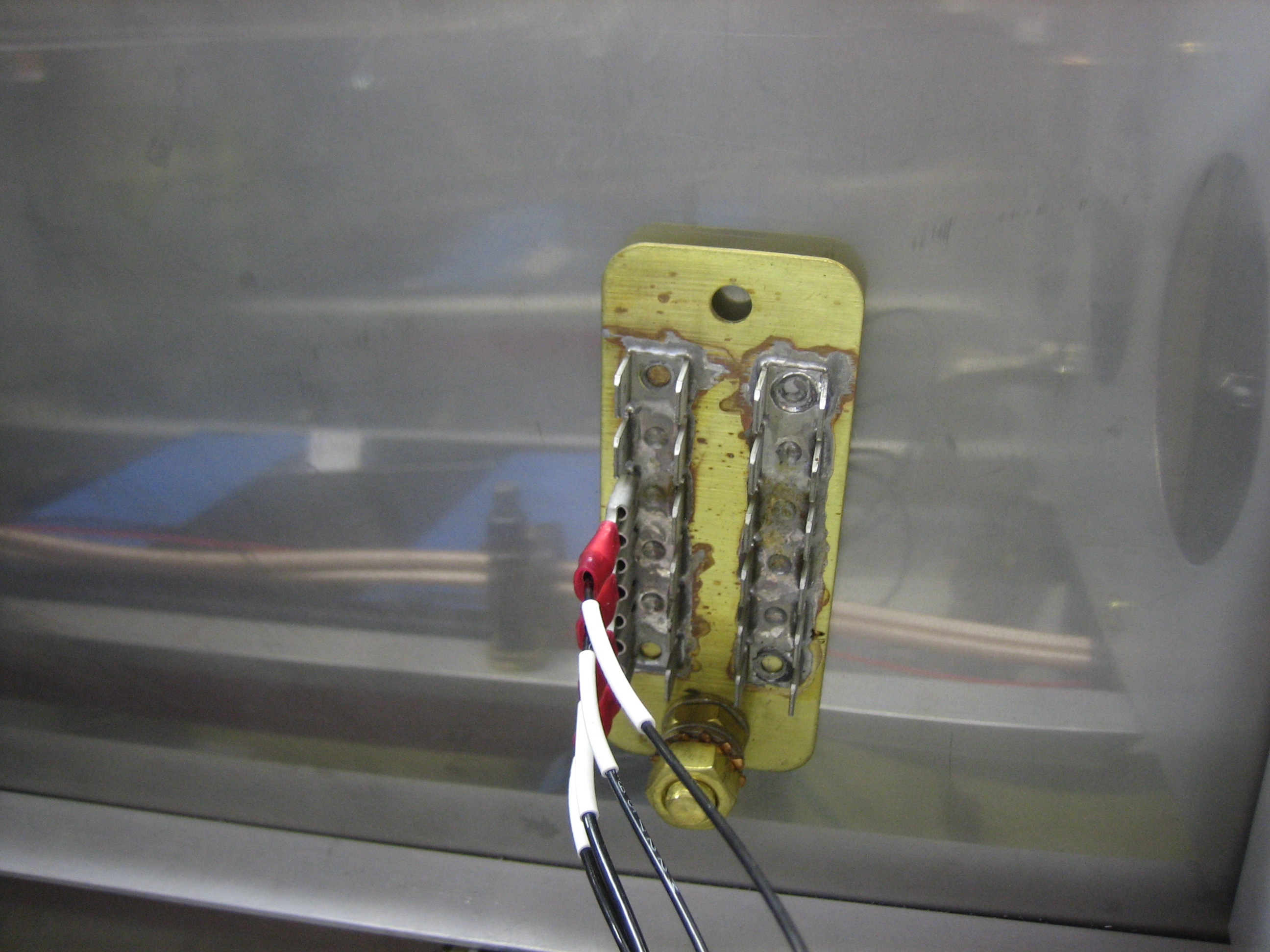
I ended up turning my ground block vertical.  I’m really glad I held off on drilling the other hole in this.  I’m going to hold off as long as possible in case I need to order a larger one.  If I can use this one, I may turn it another 90º clockwise so that it’s still horizontal.

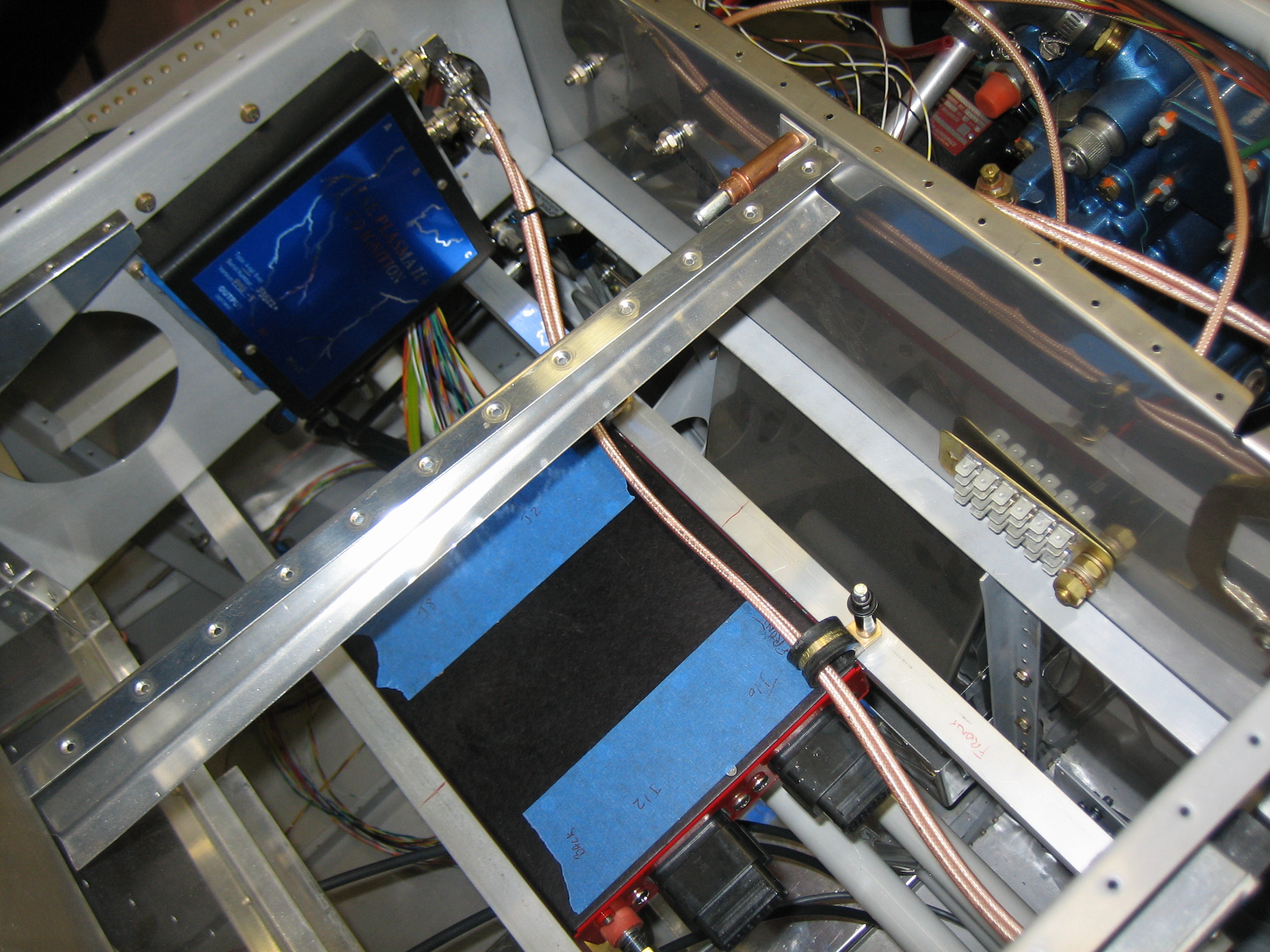
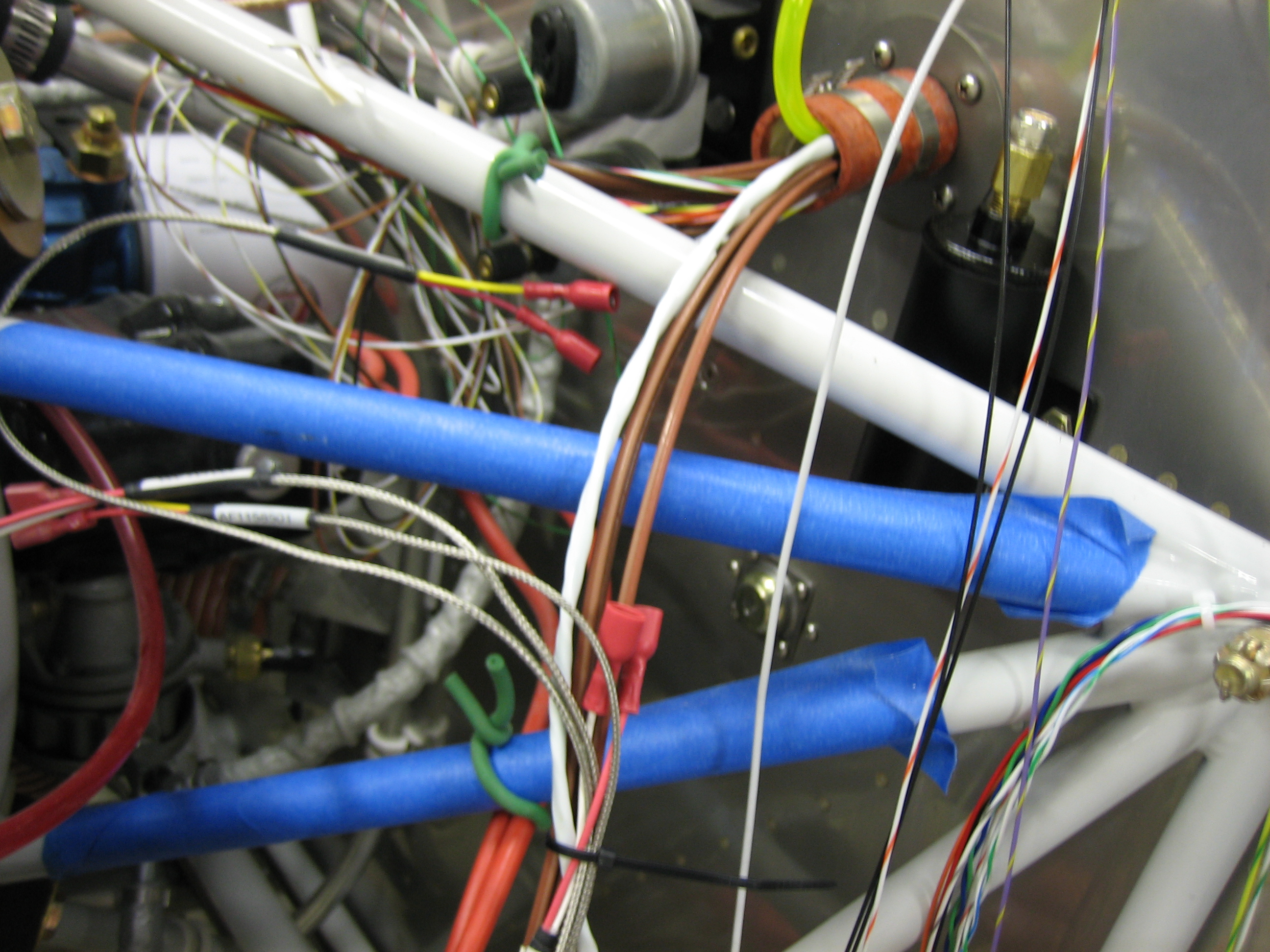
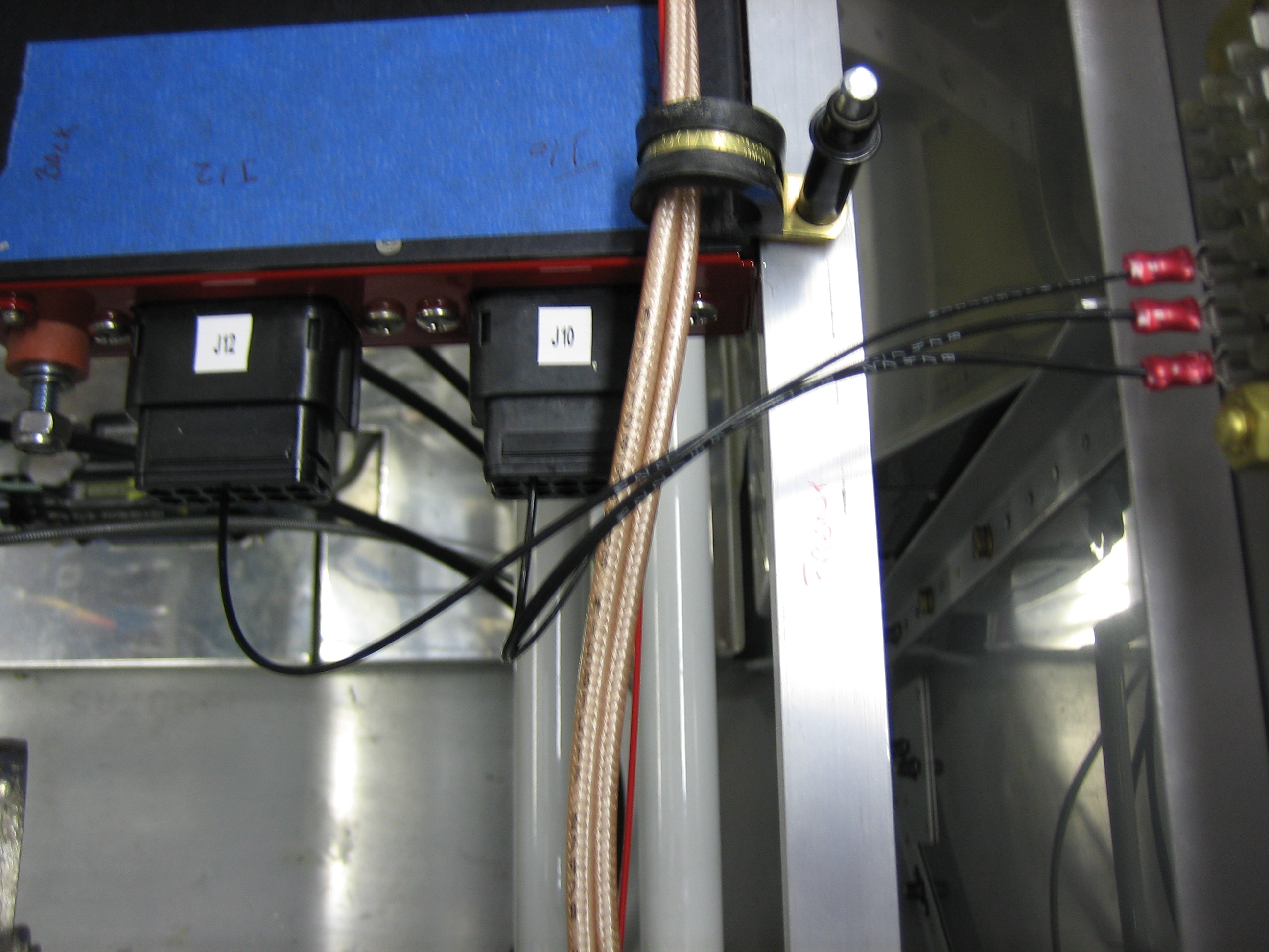
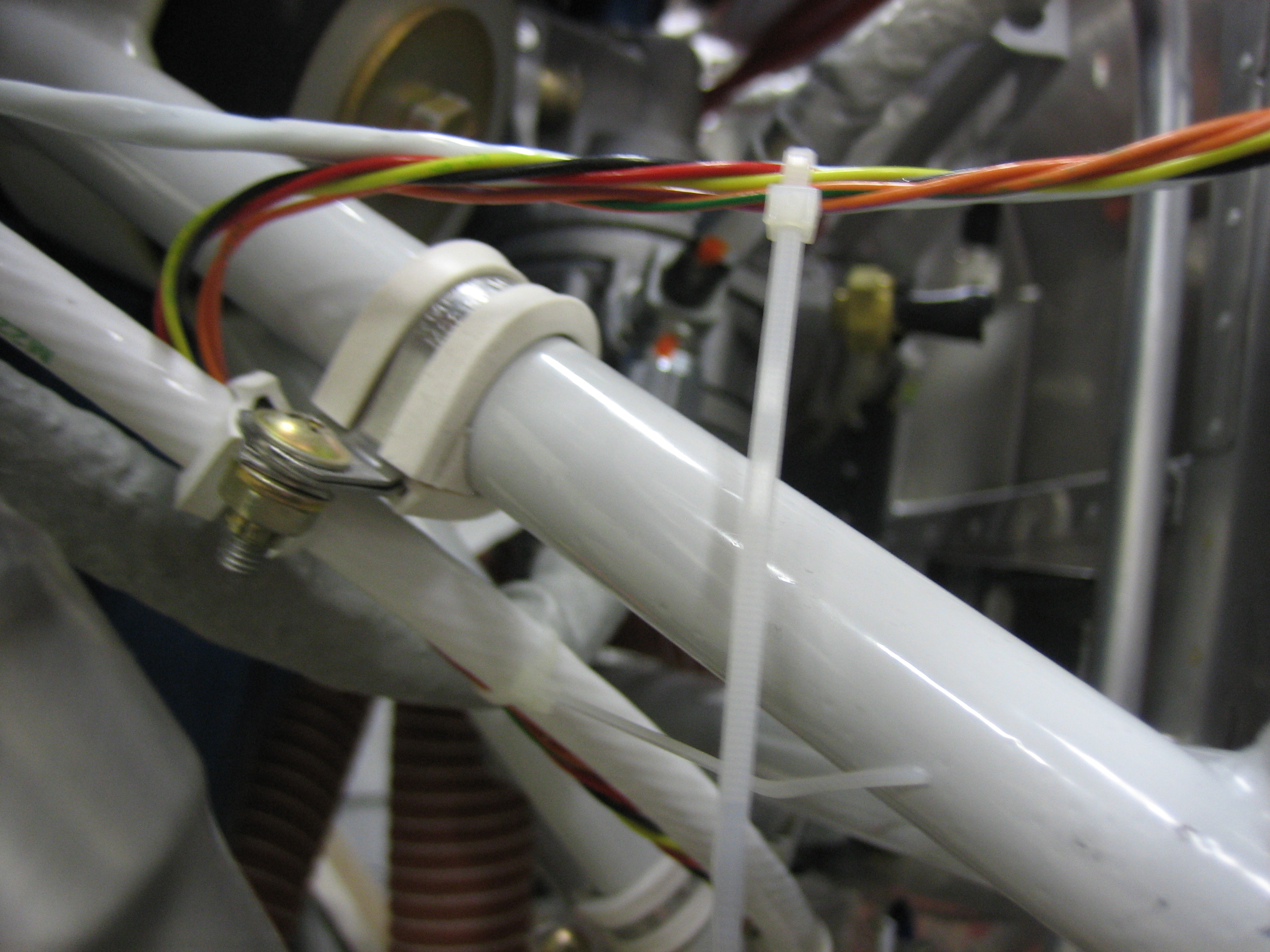
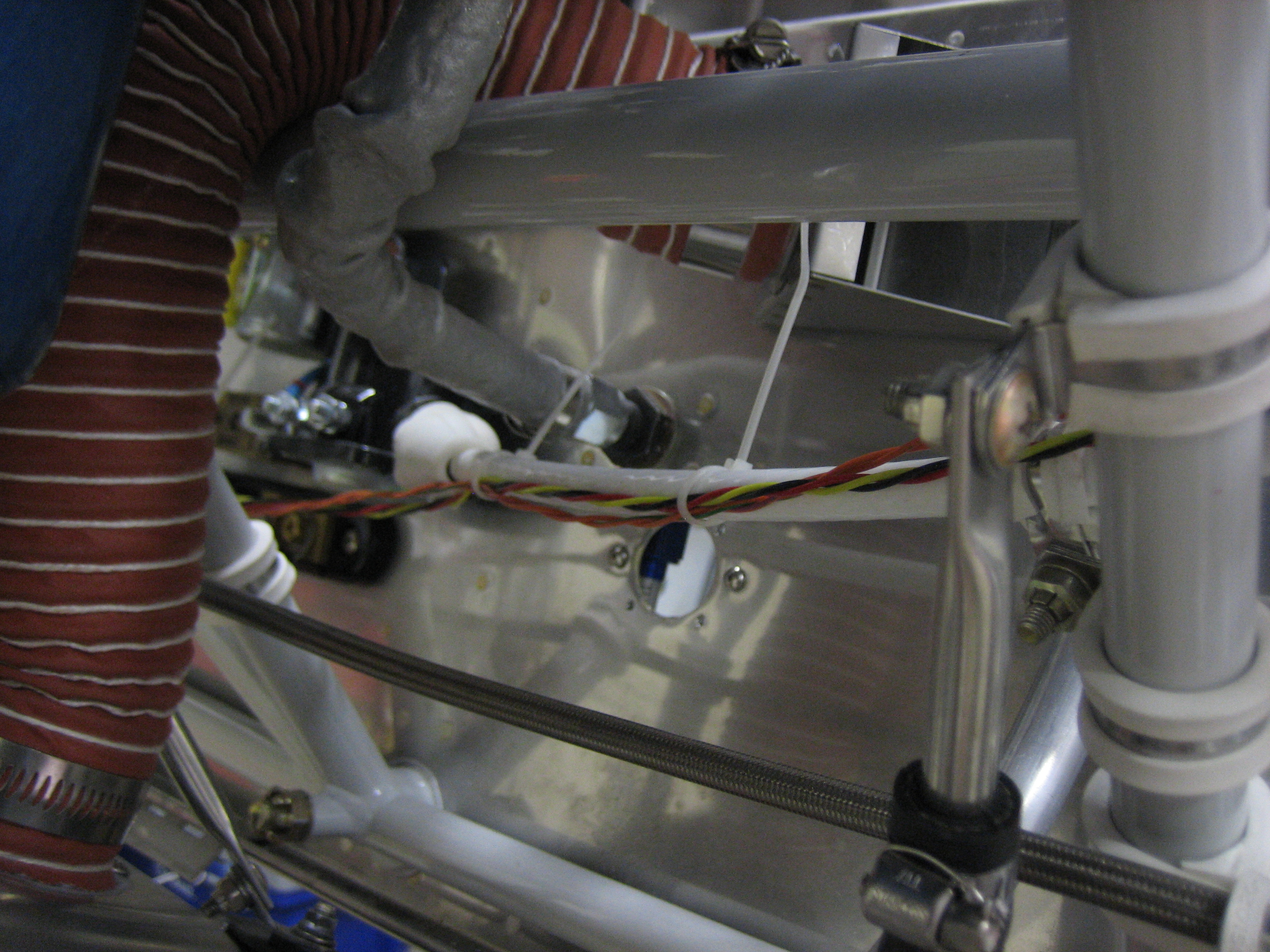
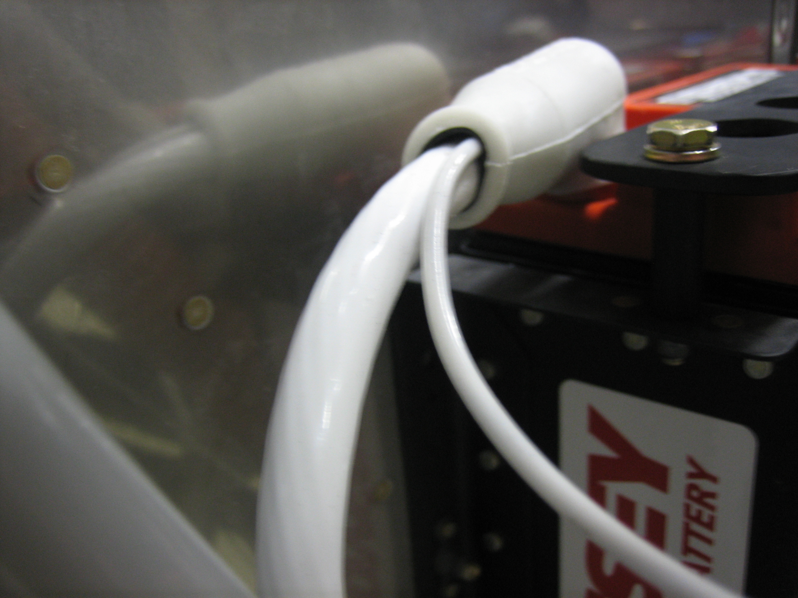
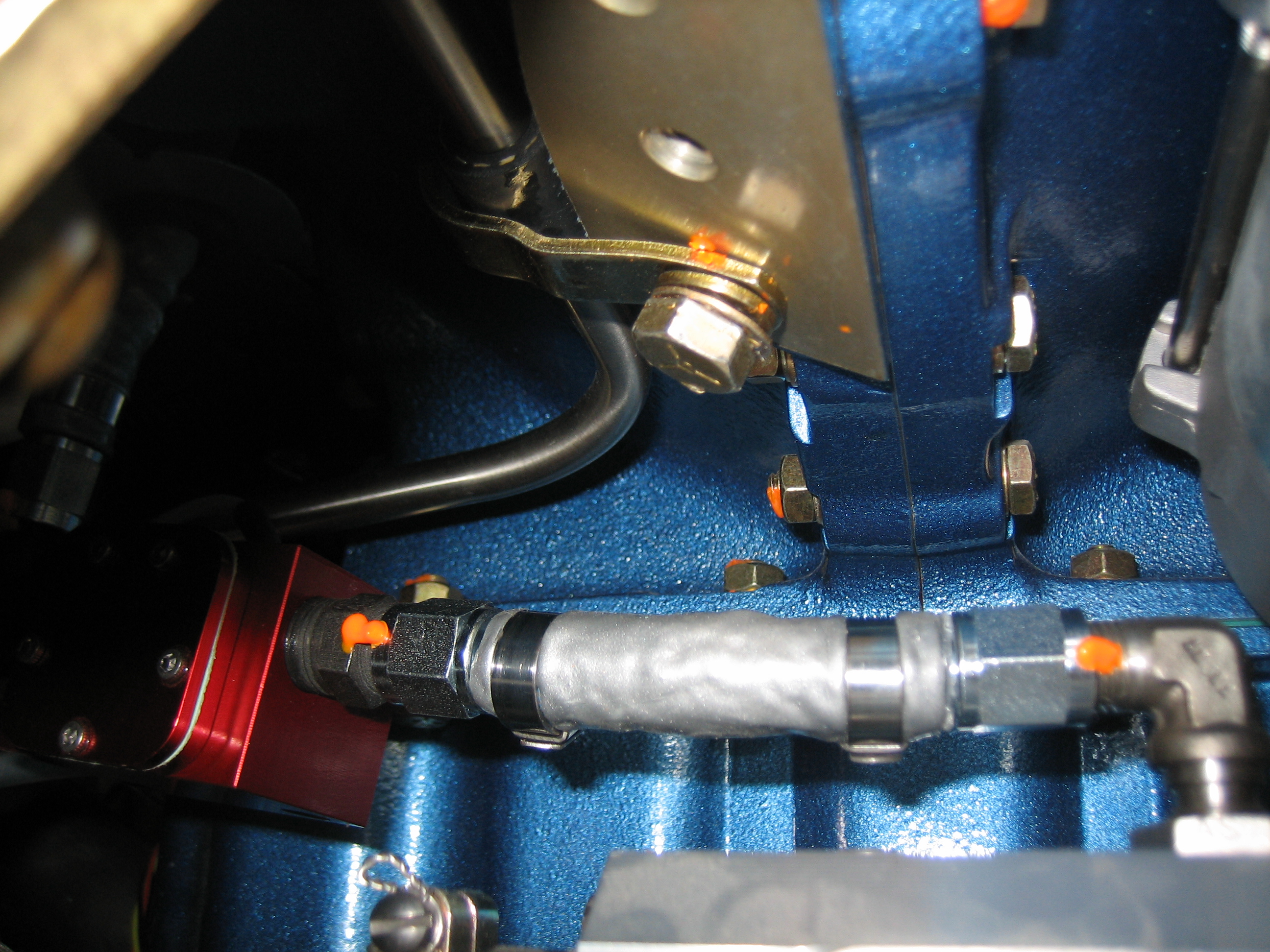
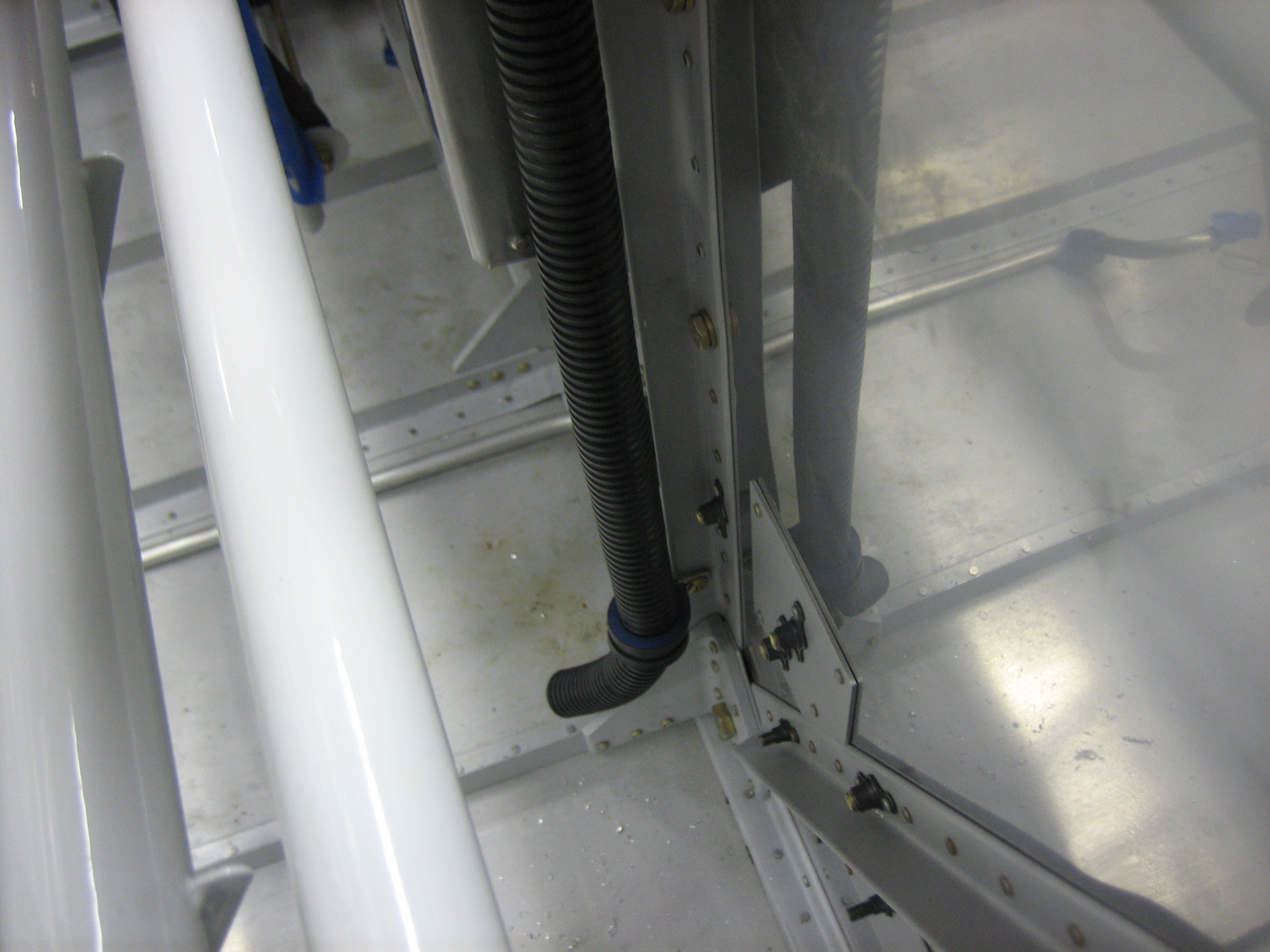
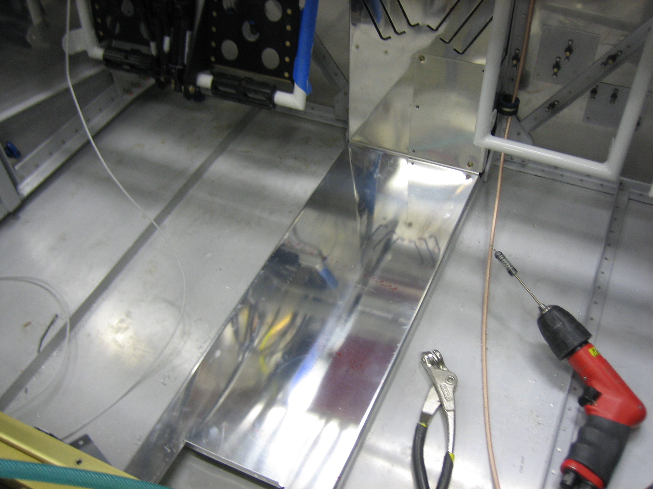
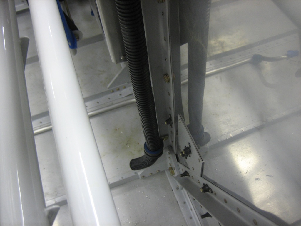
Here’s the reason I turned the ground block.  I installed the firewall wiring conduit per drawing OP-30.  This will be used to route wires front the front of the aircraft to everywhere aft of here.

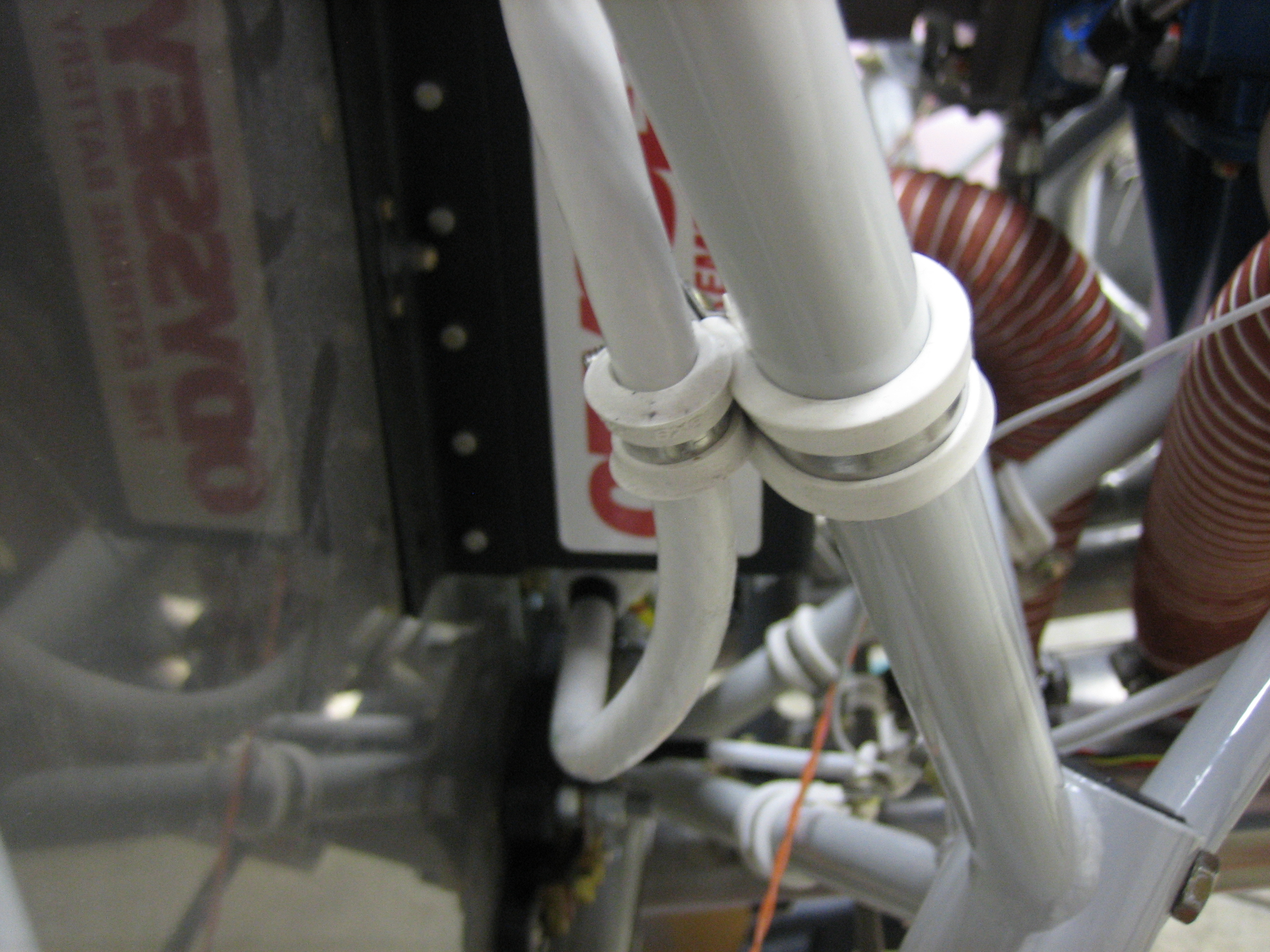
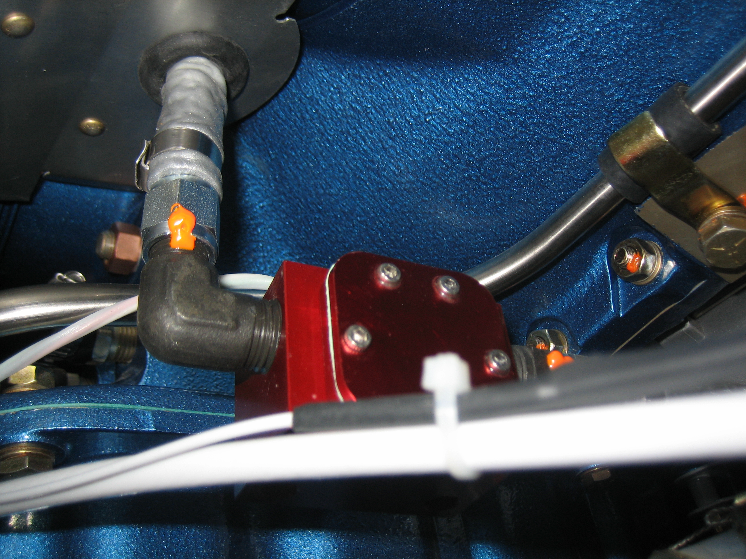
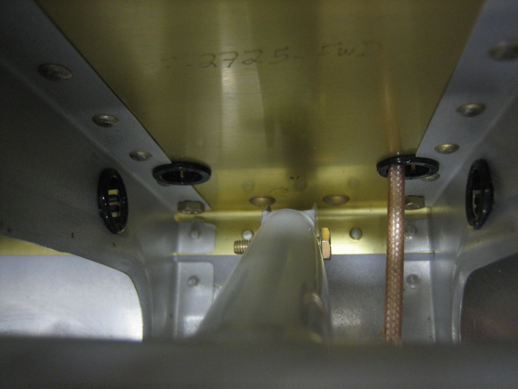
The conduit follows one of the firewall stiffeners and goes through another adel clamp near the bottom.  It then steps inside the stiffener (where there is already a hole in the cover) and will go under the center floor cover back to the spar.

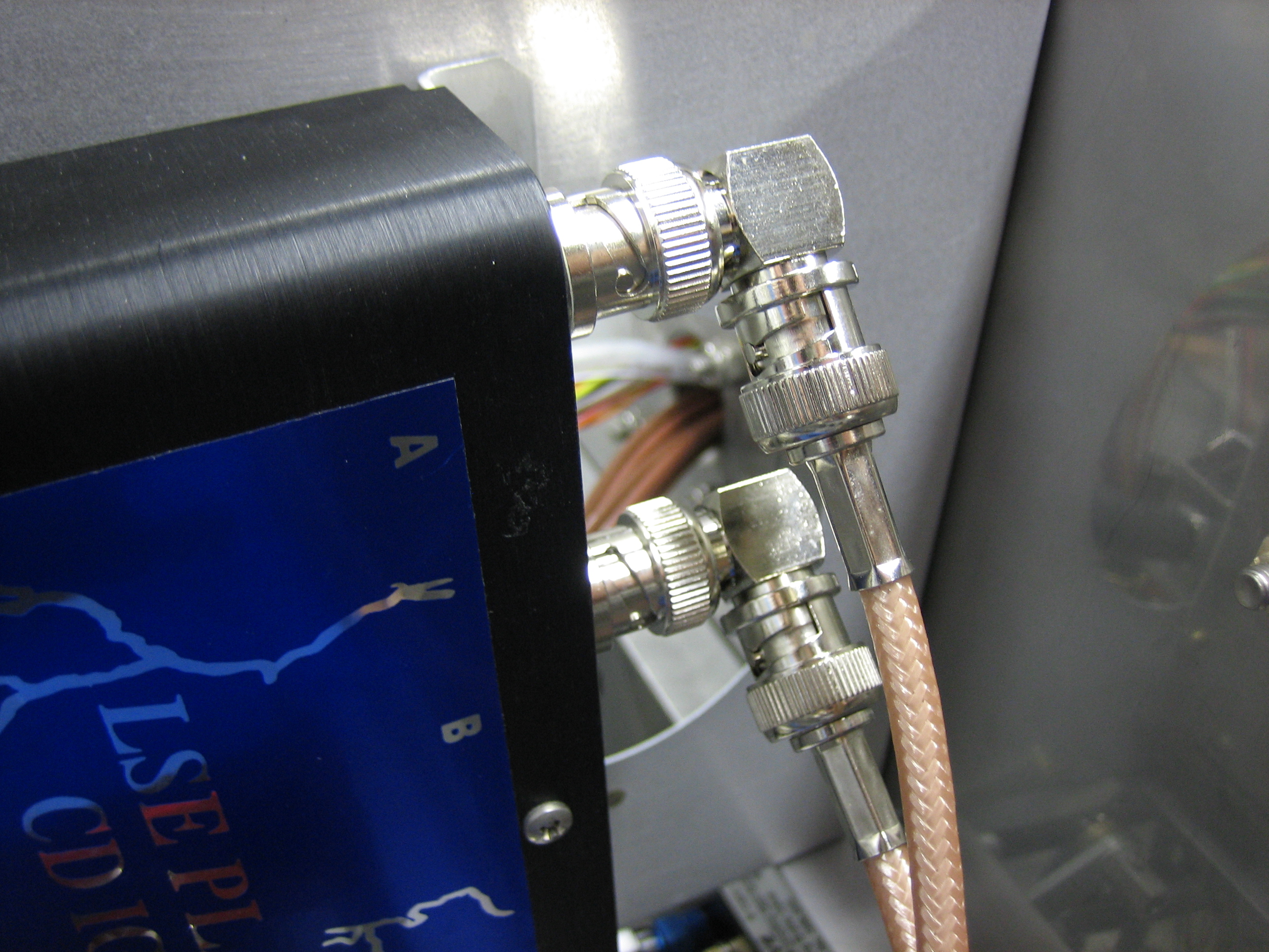
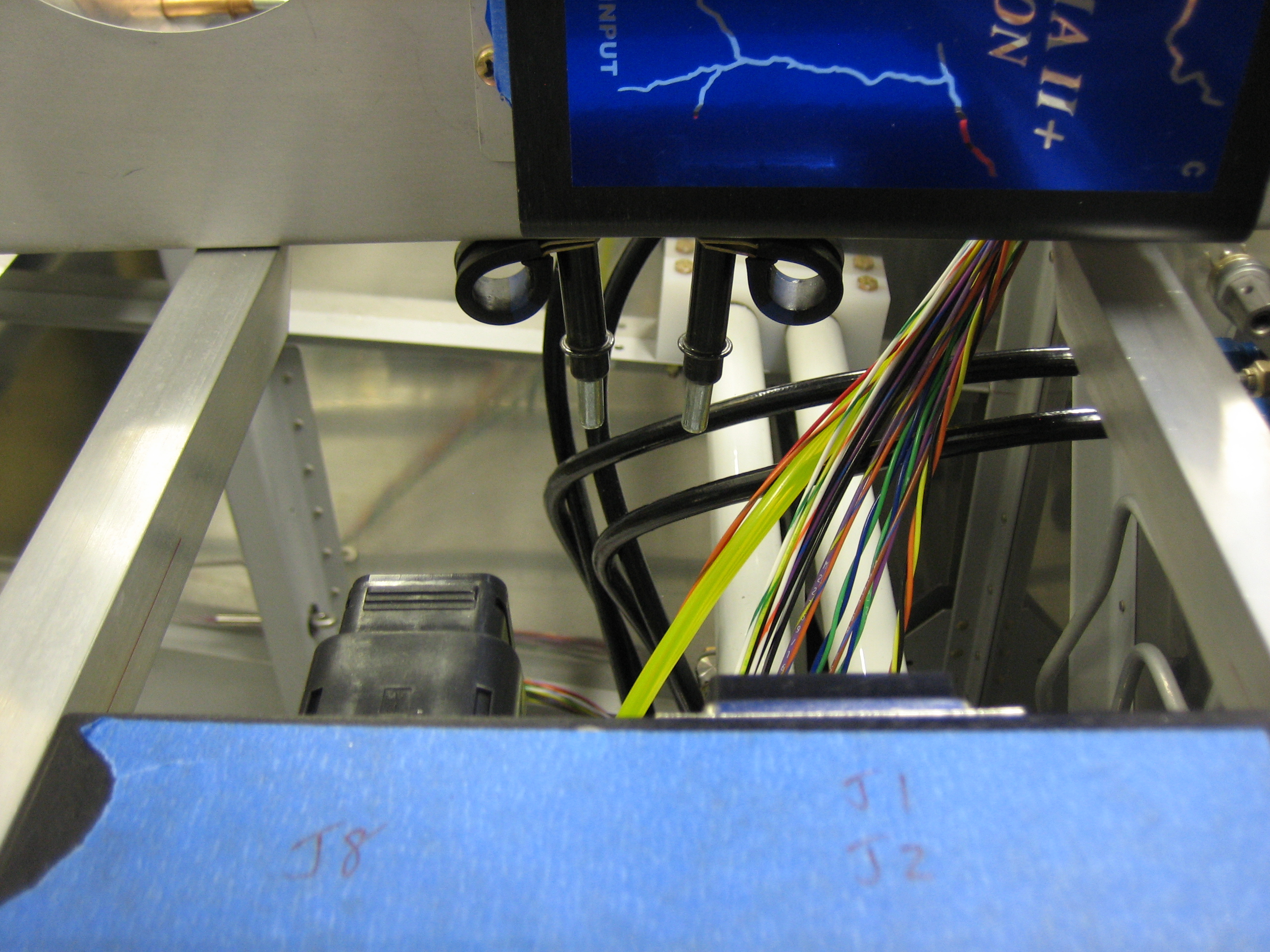
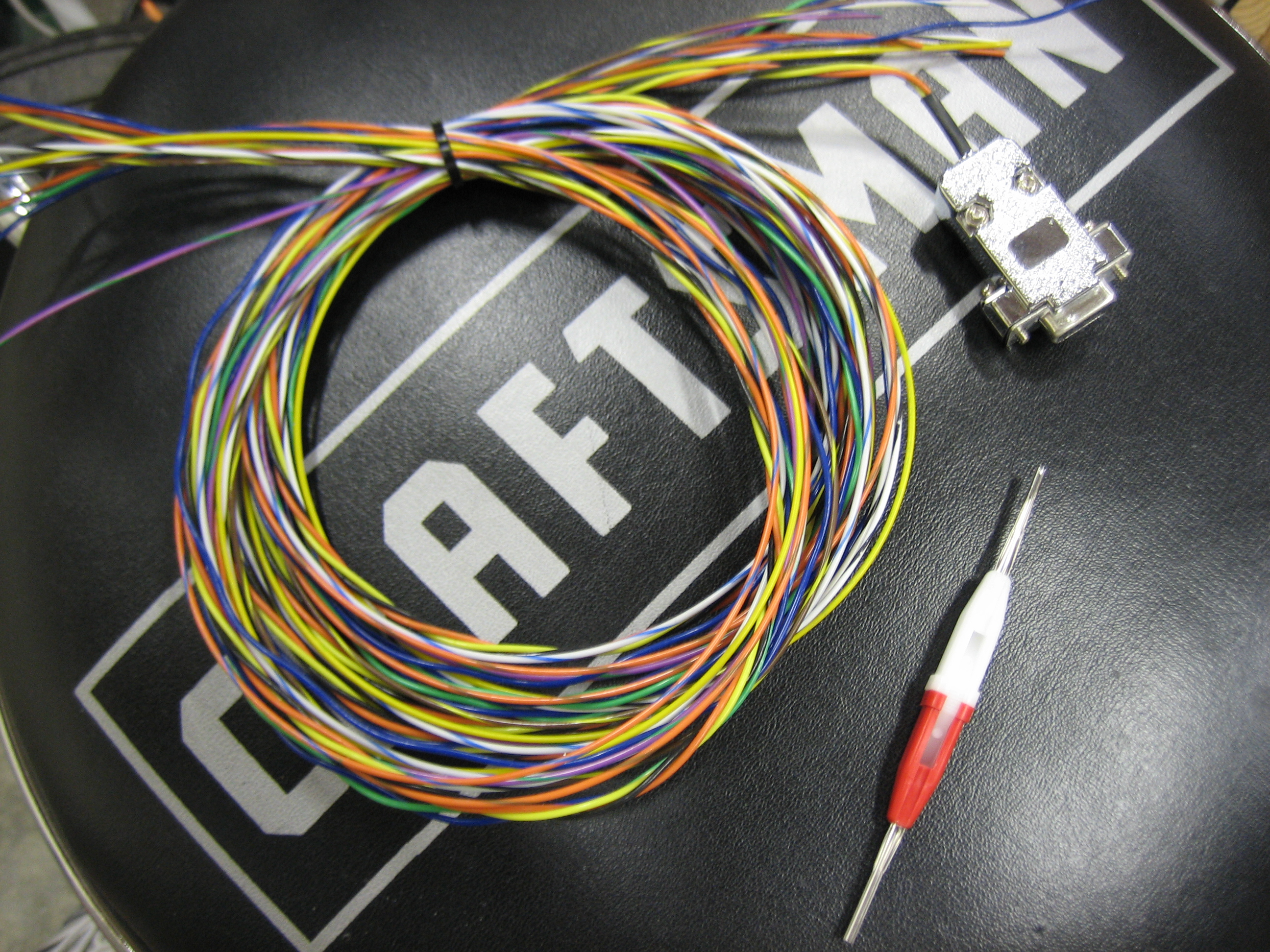
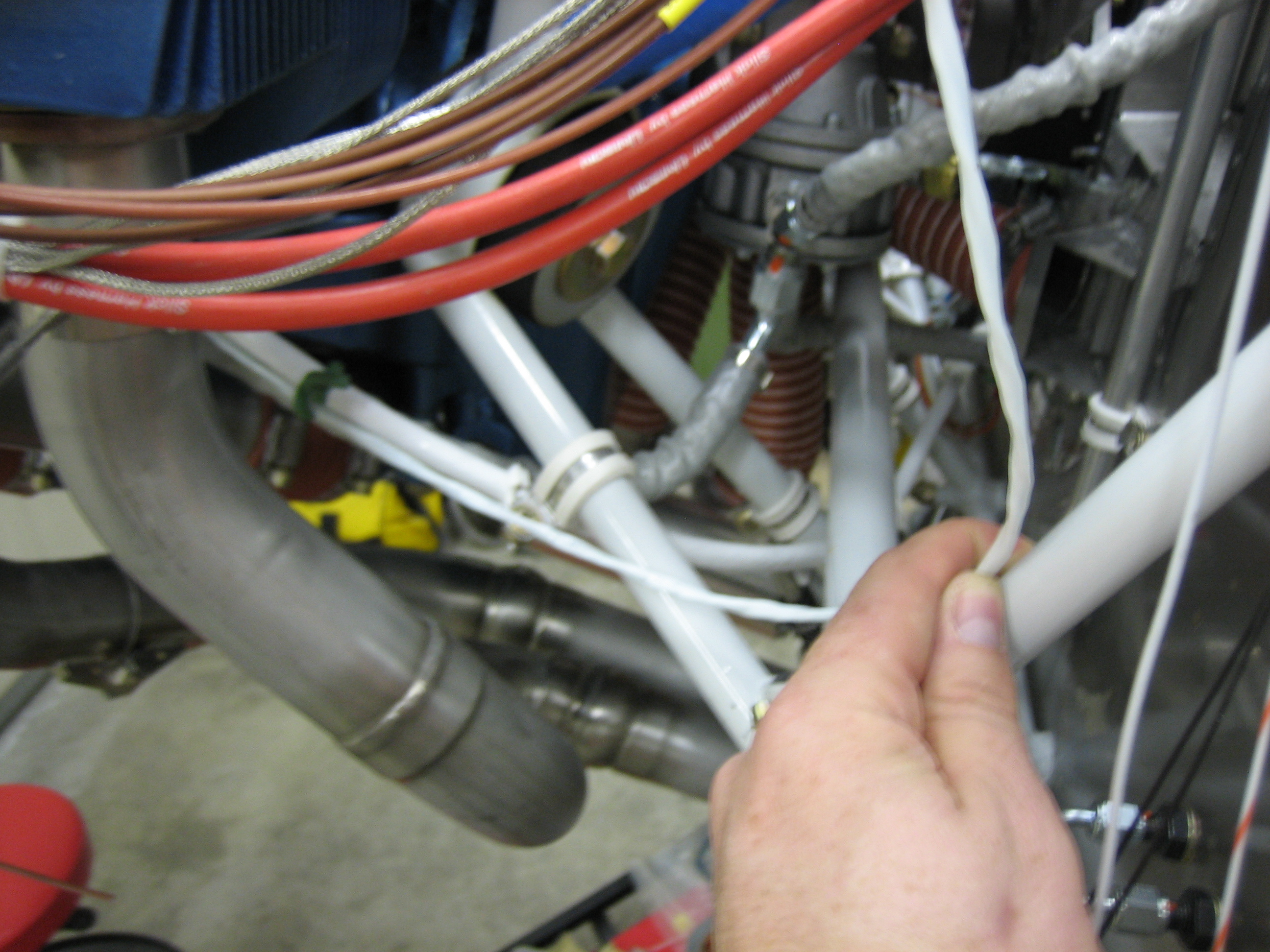
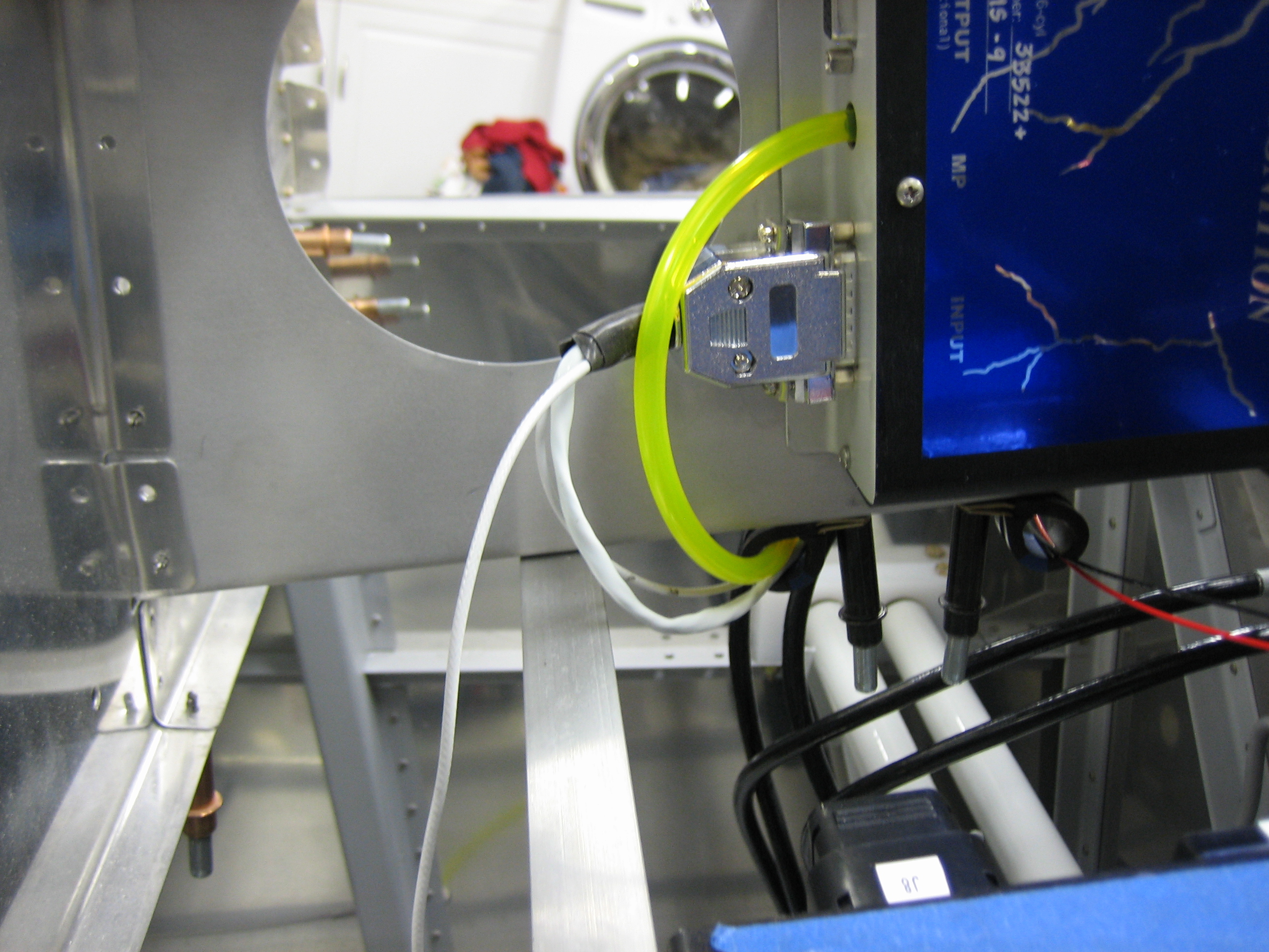
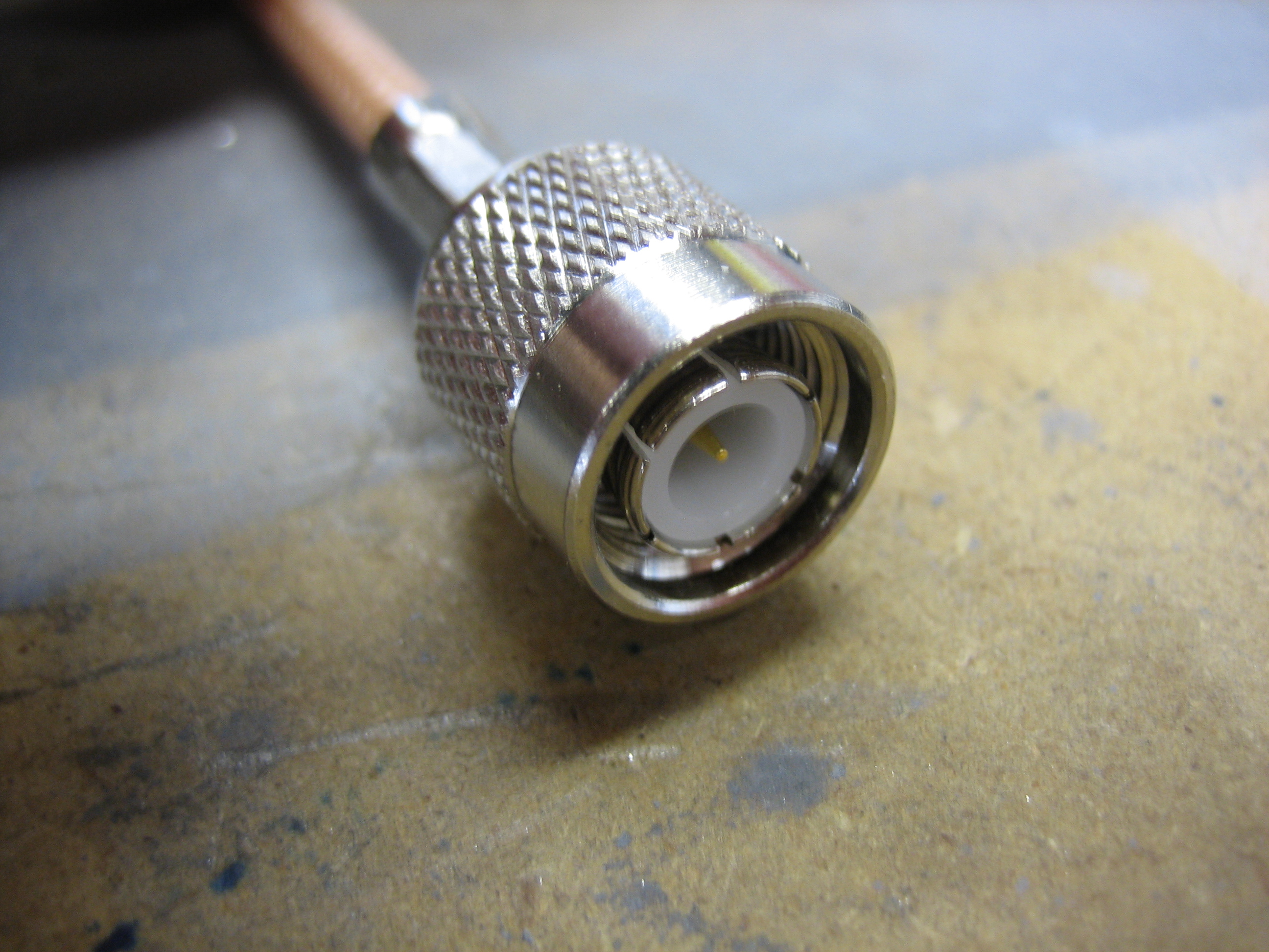
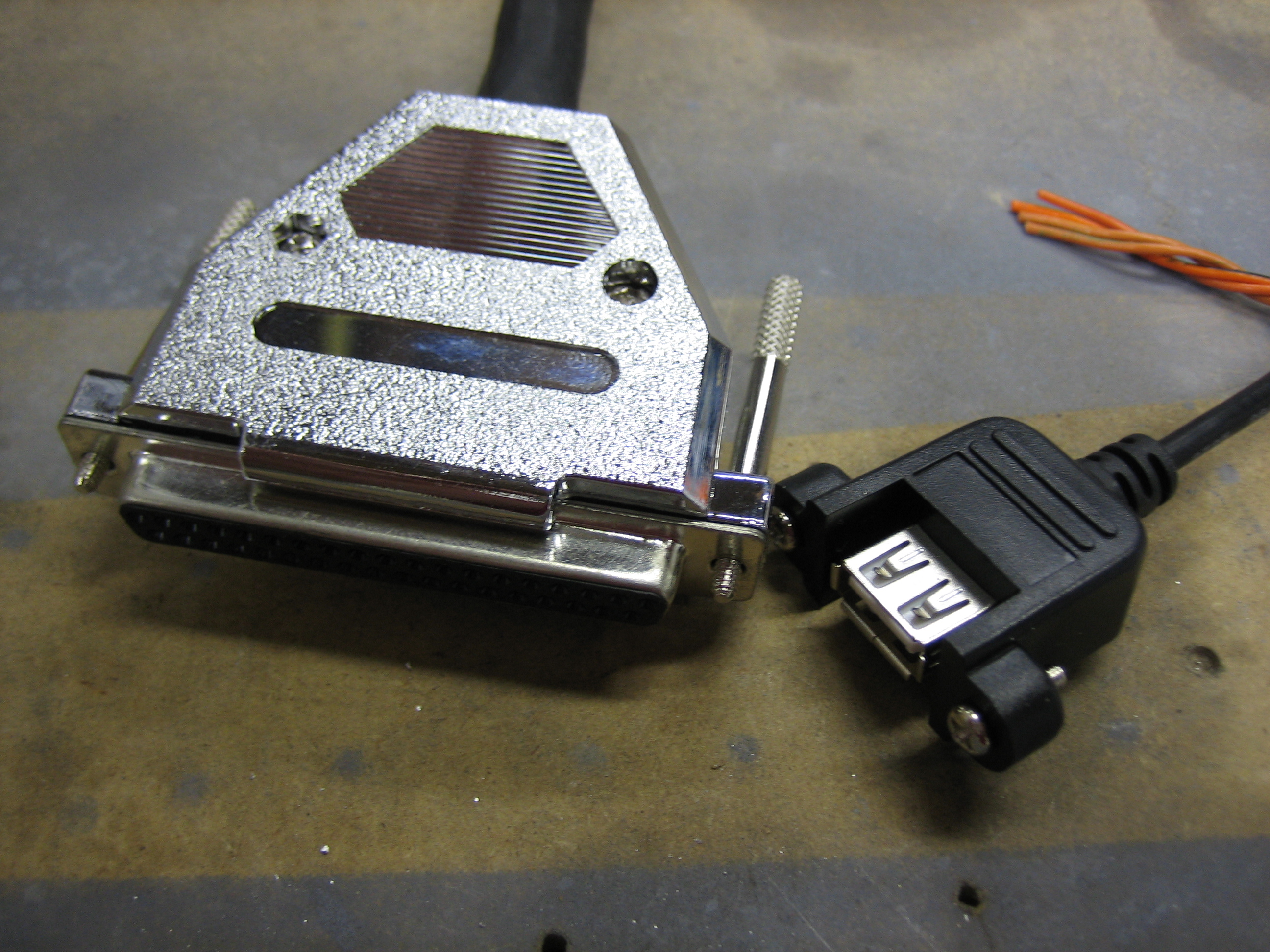
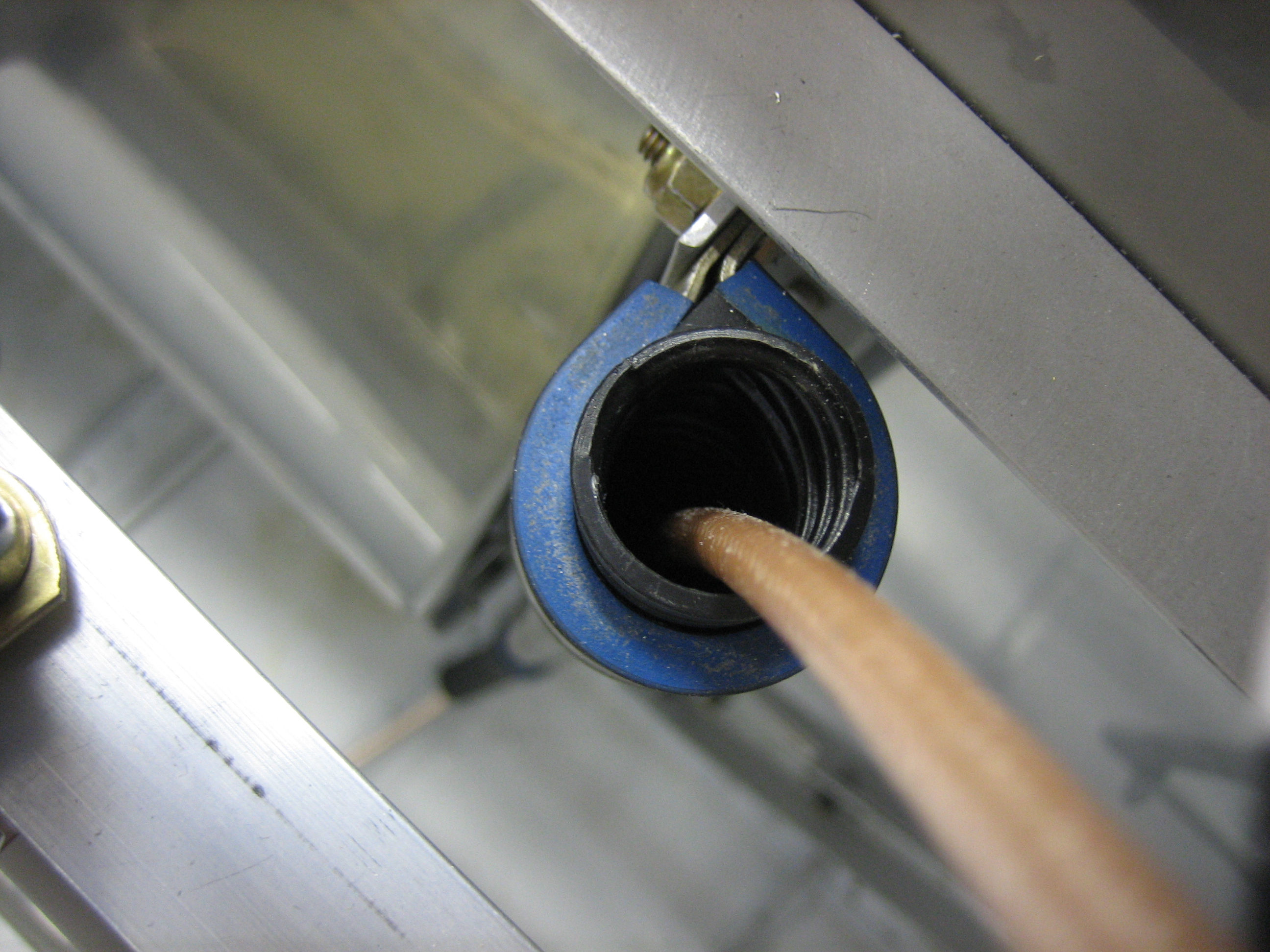
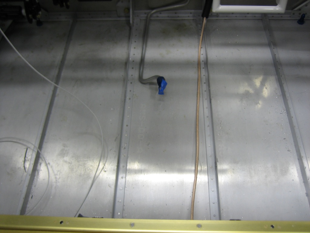
I pushed a piece of RG-400 through the conduit to get an idea how much space I’ll have in the conduit and figure out how I’m going to route the wires.  There are going to be a ton of wires that have to run through this conduit:

  • COM antenna[s]
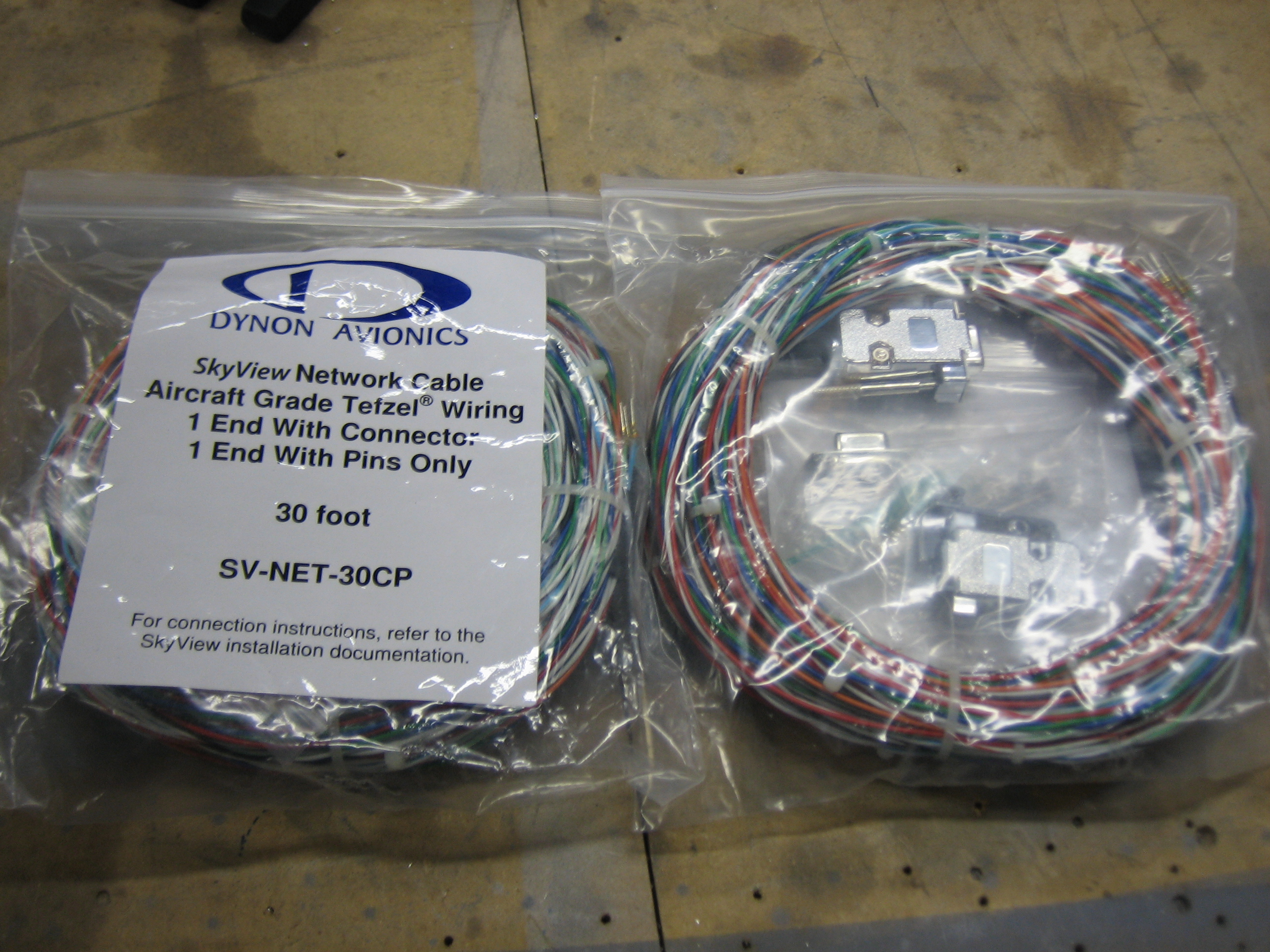
  • SkyView network cable
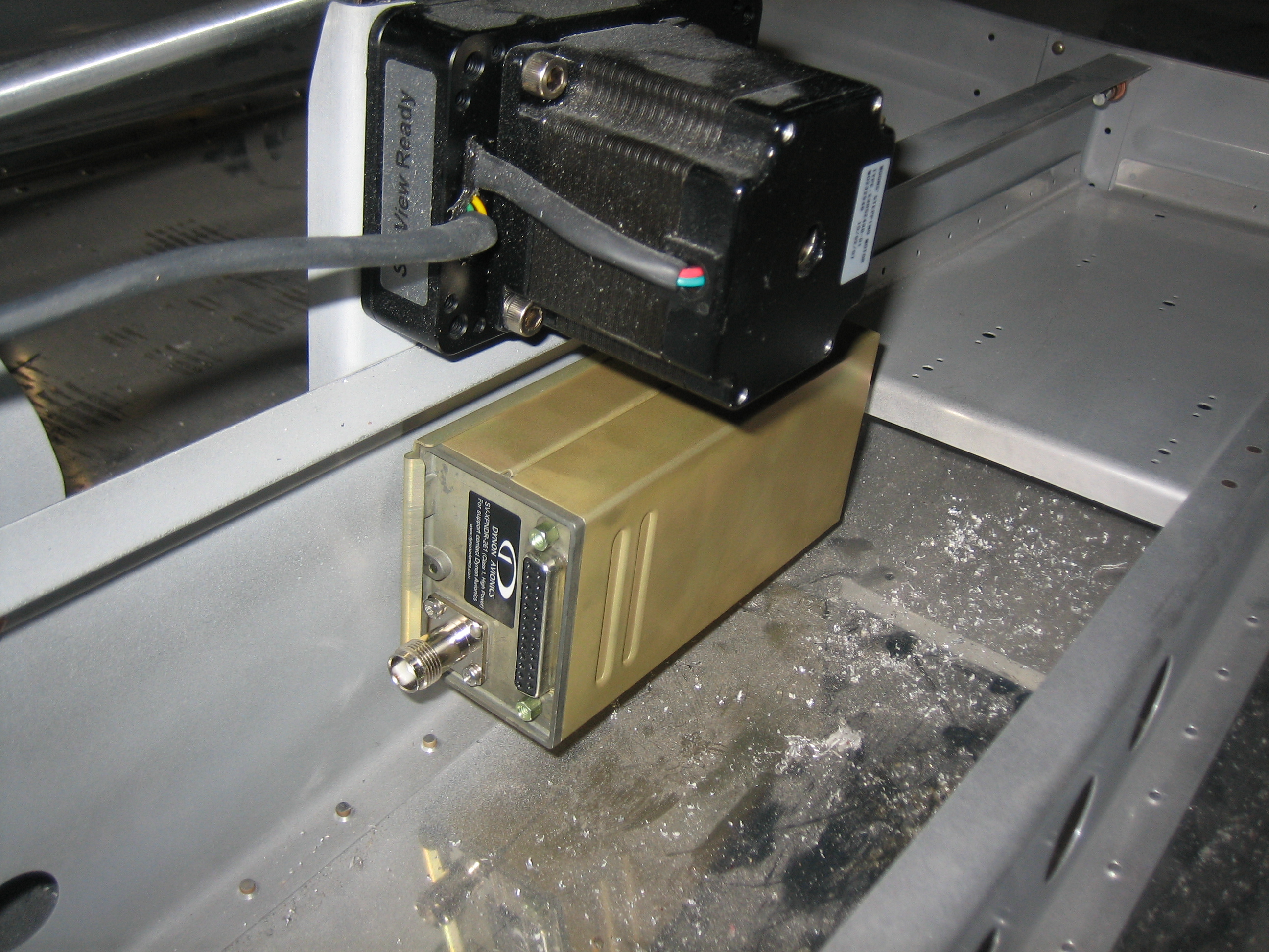
  • Transponder power, ground, and serial wires
  • Autopilot servo power/ground wires
  • Stick trim and PTT wires
  • Aileron and elevator trim wires
  • Landing, taxi, NAV, and strobe wires
  • Flap motor and position sensor wires
  • Cabin light wires
  • Seat heater wires

Geez, after listing all these, I can’t possibly see that they’ll all fit through the conduit (even though most are pretty small relative to the RG-400).  I’ll either run the wires through the adel clamps directly and wrap the wires with split tubing, or possibly run a second conduit down the left side of the center section.

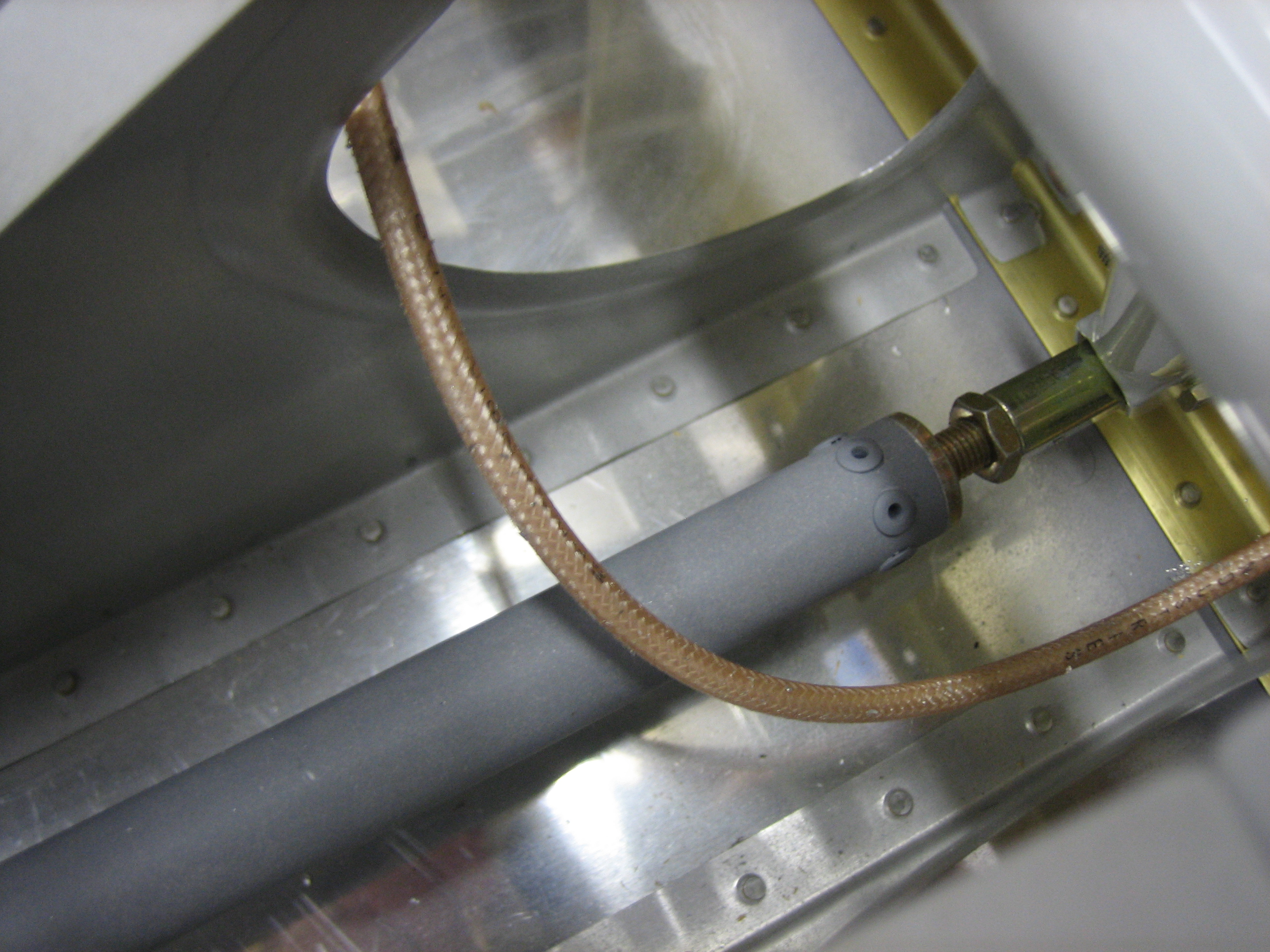
The wires exit the bottom of the conduit and will run along the floor.  I’ll add anchors along the floor to keep the bundle secure.

The wire exits the back of the spar near where the elevator horn sits.  I’m not sure I like where Van’s suggests you put the snap bushings in the ribs.  The wires have to make a fairly sharp turn to go through the ribs.  This is fine for all of the small wires, but the RG-400 has a minimum bend radius of 1″, so that might not work.

Another possibility I’ve seen builders use is to cross the wires and penetrate the rib on the opposite side of the spar penetration (though obviously below the push tube).  I’d need to drill new rib penetrations which would be challenging given the spacing between the ribs.  This certainly allows a generous bend radius in the wires though.

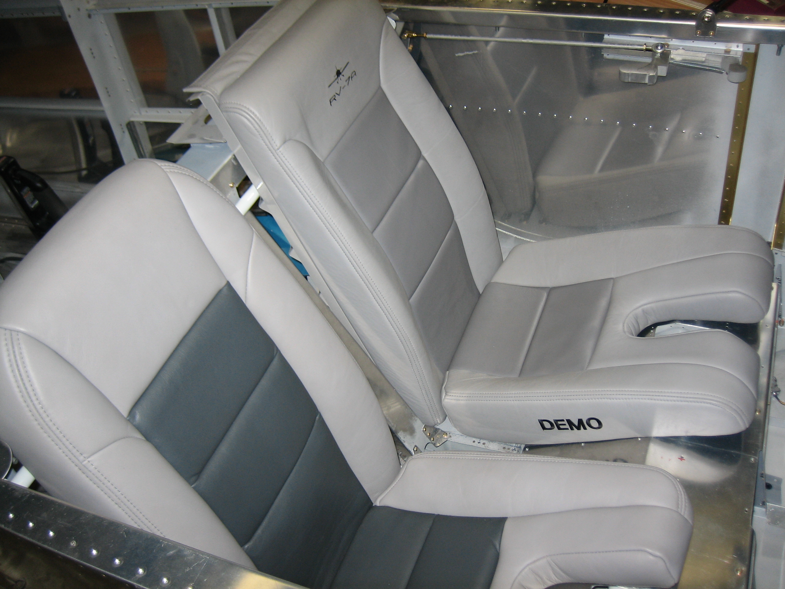
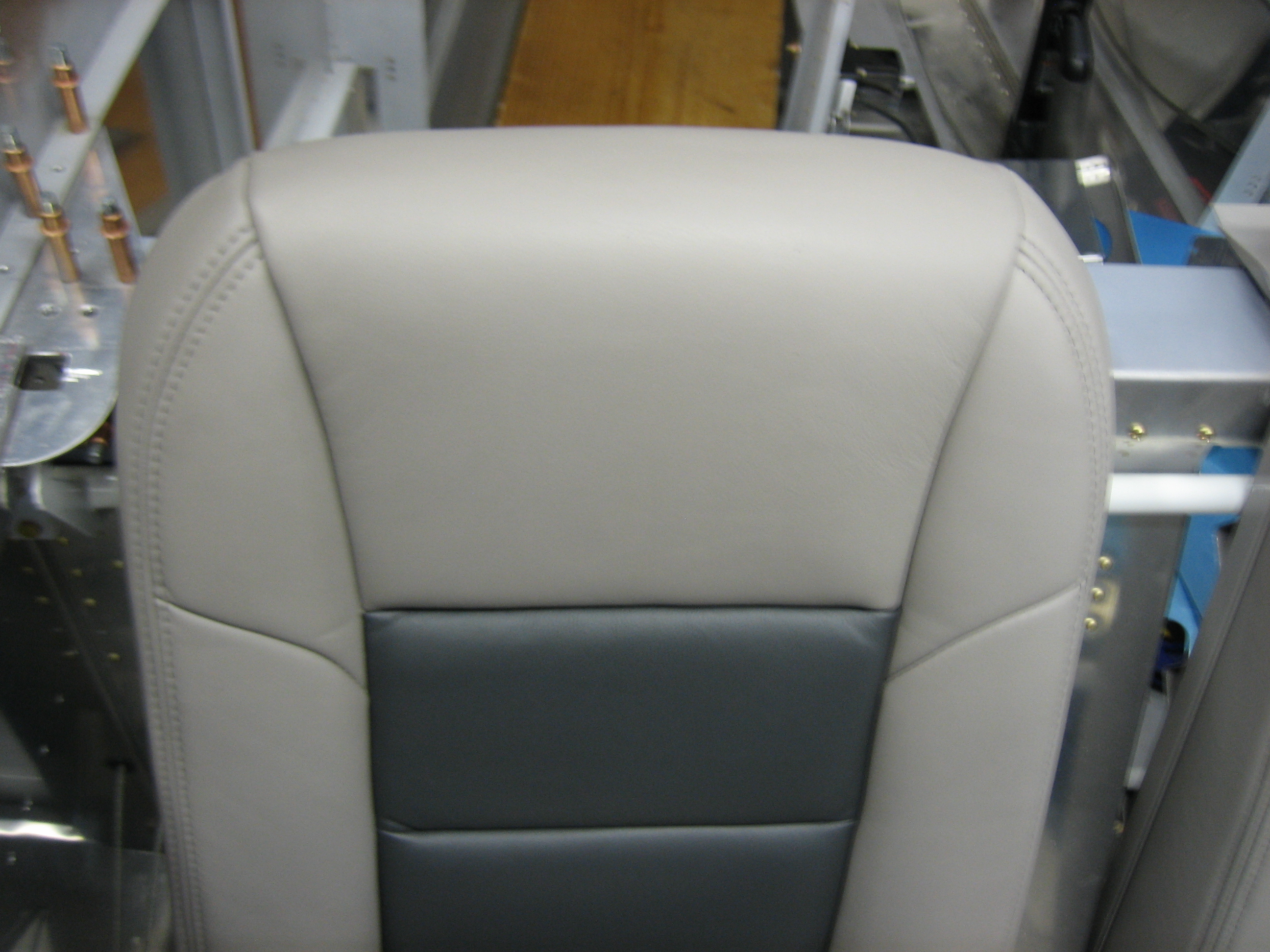
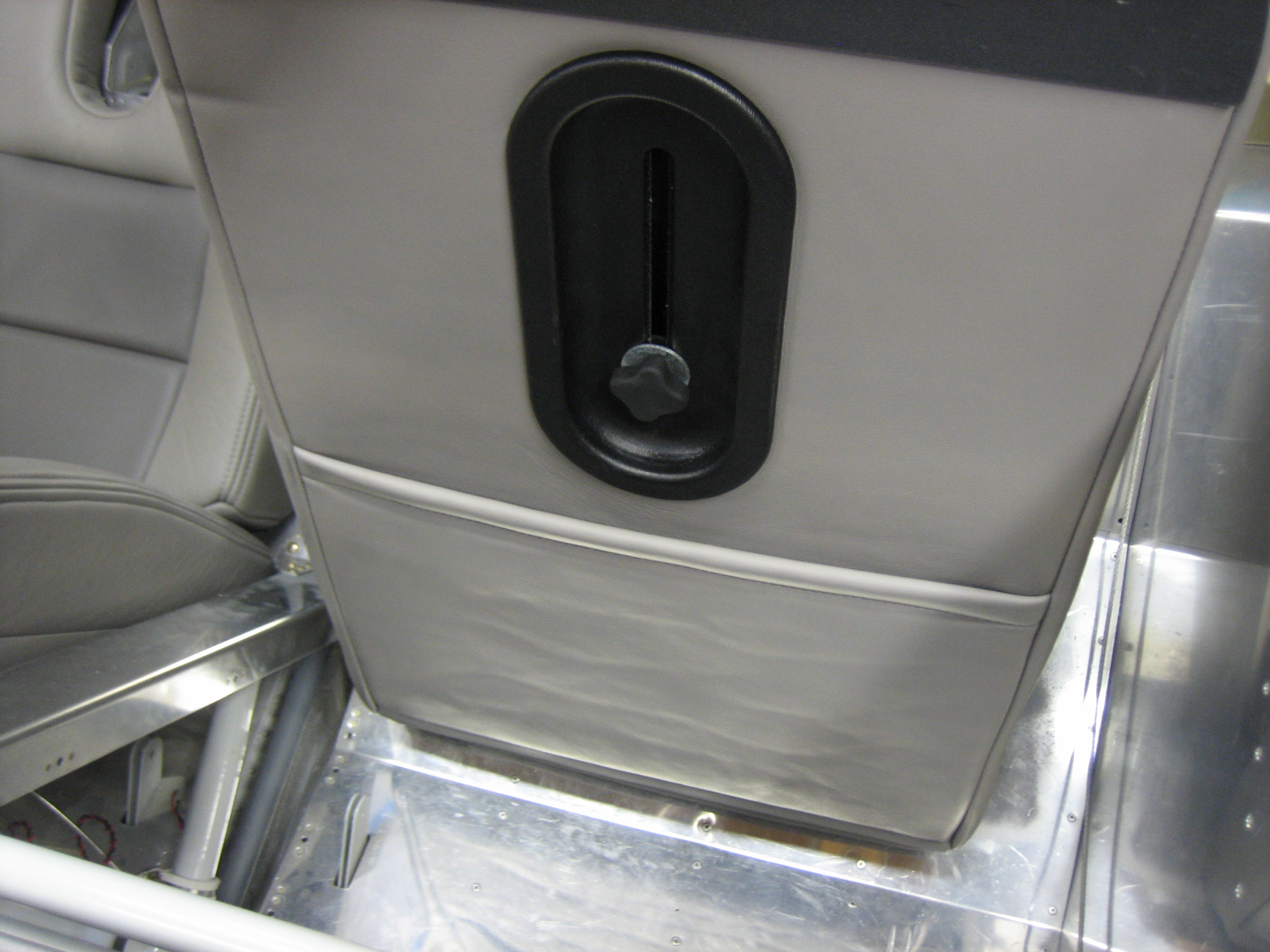
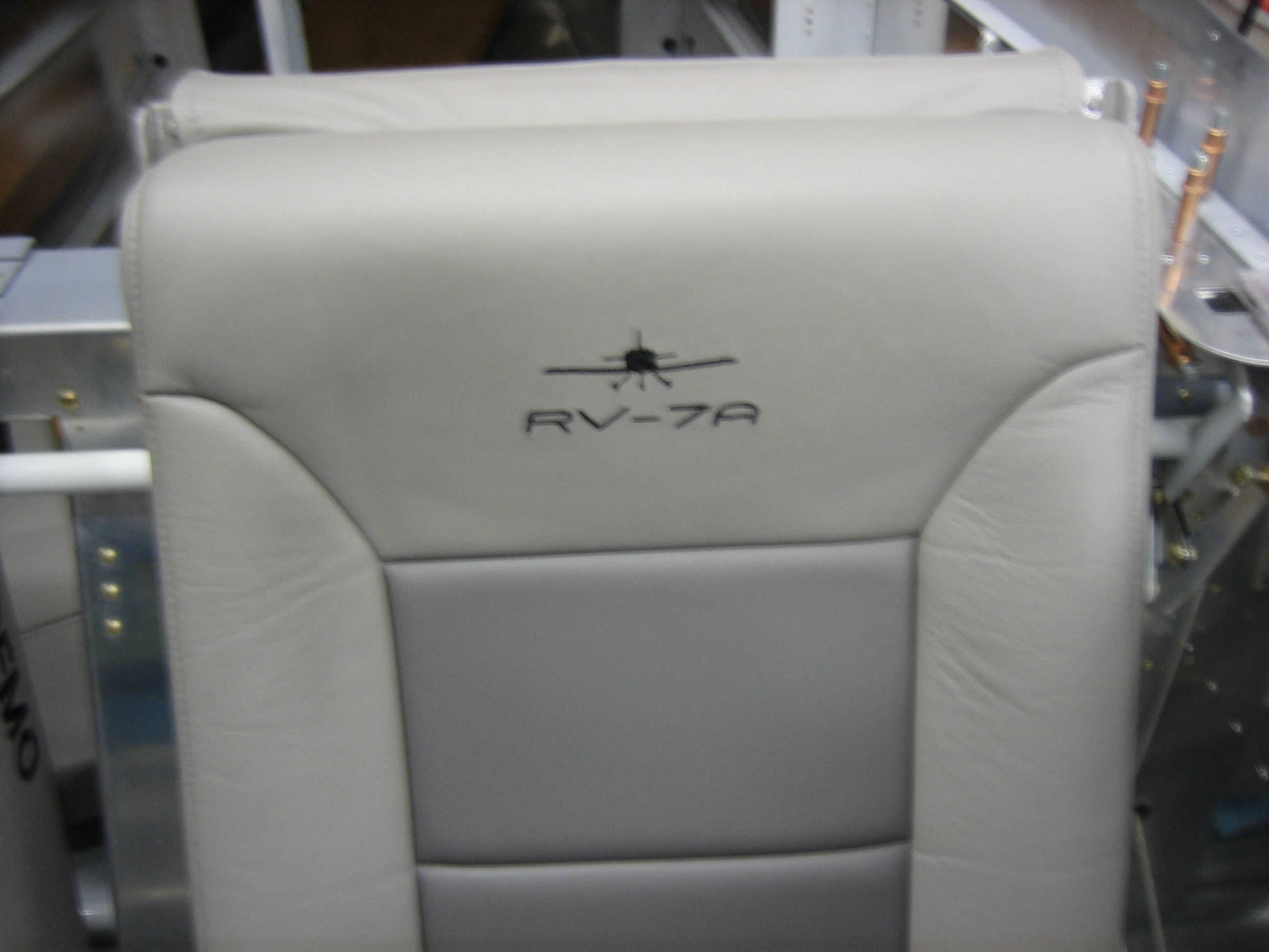
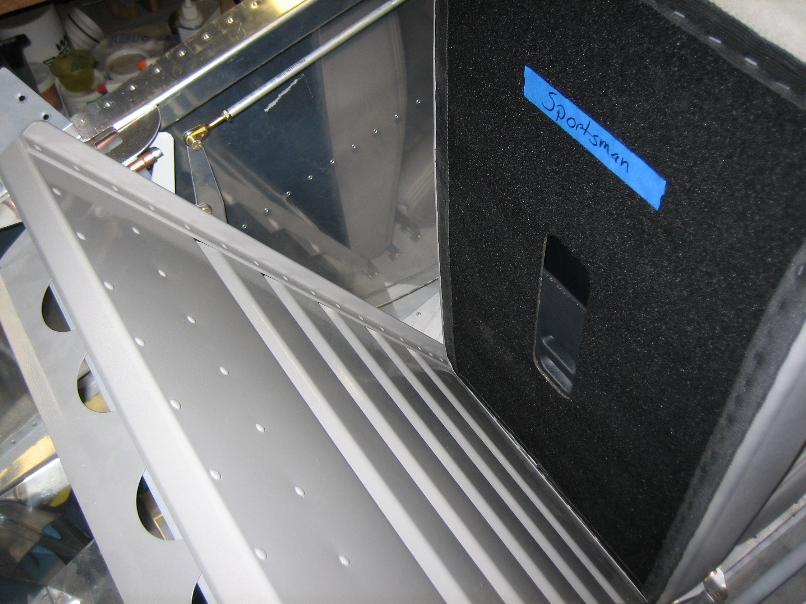
I also ordered my interior from Classic Aero Designs.  I’m going with the aviator seats with headrests, side panels, and full carpet.  I also added in the hooker harnesses with matching leather pads.  This will be a relatively heavy interior compared with the minimal cloth interior that many builders go with, but I really want a completely finished leather interior.

Removed Firewall Conduit and Worked on New Center Cover

I added up all the wires that will need to go through the conduit, and it was pretty clear that they weren’t all going to fit.  I could either run a second conduit down the left side, or simply run the wires through the adel clamps directly and then wrap them with a split conduit which seems like the simpler option.

I decided to order a new center section cover from Van’s.  If you recall, I had to move the electric fuel pump forward a bit because I couldn’t easily fabricate the line from the fuel selector down to the fuel filter according to the dimensions in the plans.  This was going to require fabricating a custom fuel pump cover.  I was recently putting together my interior order, and the custom cover was going to complicate the floor carpet order.  I ended up deciding the easier thing to do was move the fuel pump back so that I could use the standard fuel pump cover (and hence the standard carpet).

I also played around with wire routing under the seats.  Van’s stock location just isn’t going to work.  The RG-400 would be right at the minimum bend radius and the wires have to get routed around the control stick mounts.  I’m going to have to punch additional holes in the ribs in the location I identified yesterday.

Finally, I ordered a couple of custom circuit boards today to control the annunciator lights and for the avionics interconnect.