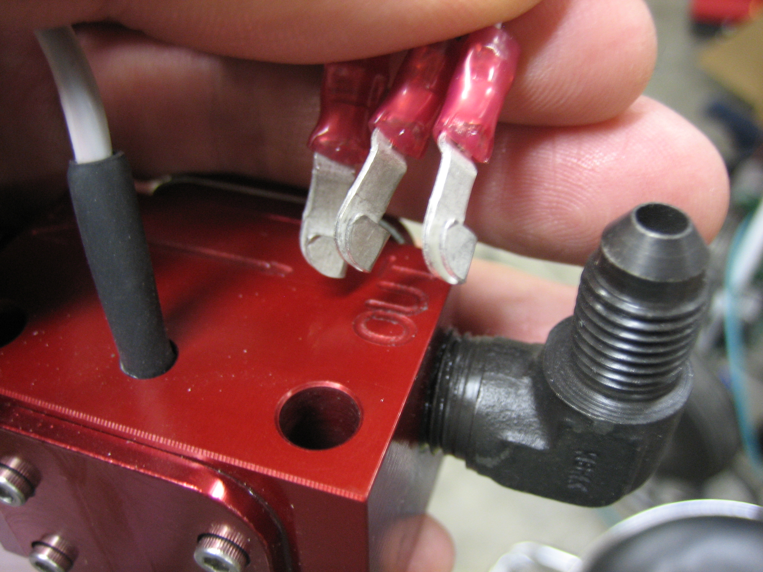
I removed the fast-on tabs from the wires on the fuel flow sensor and installed some knife connectors.
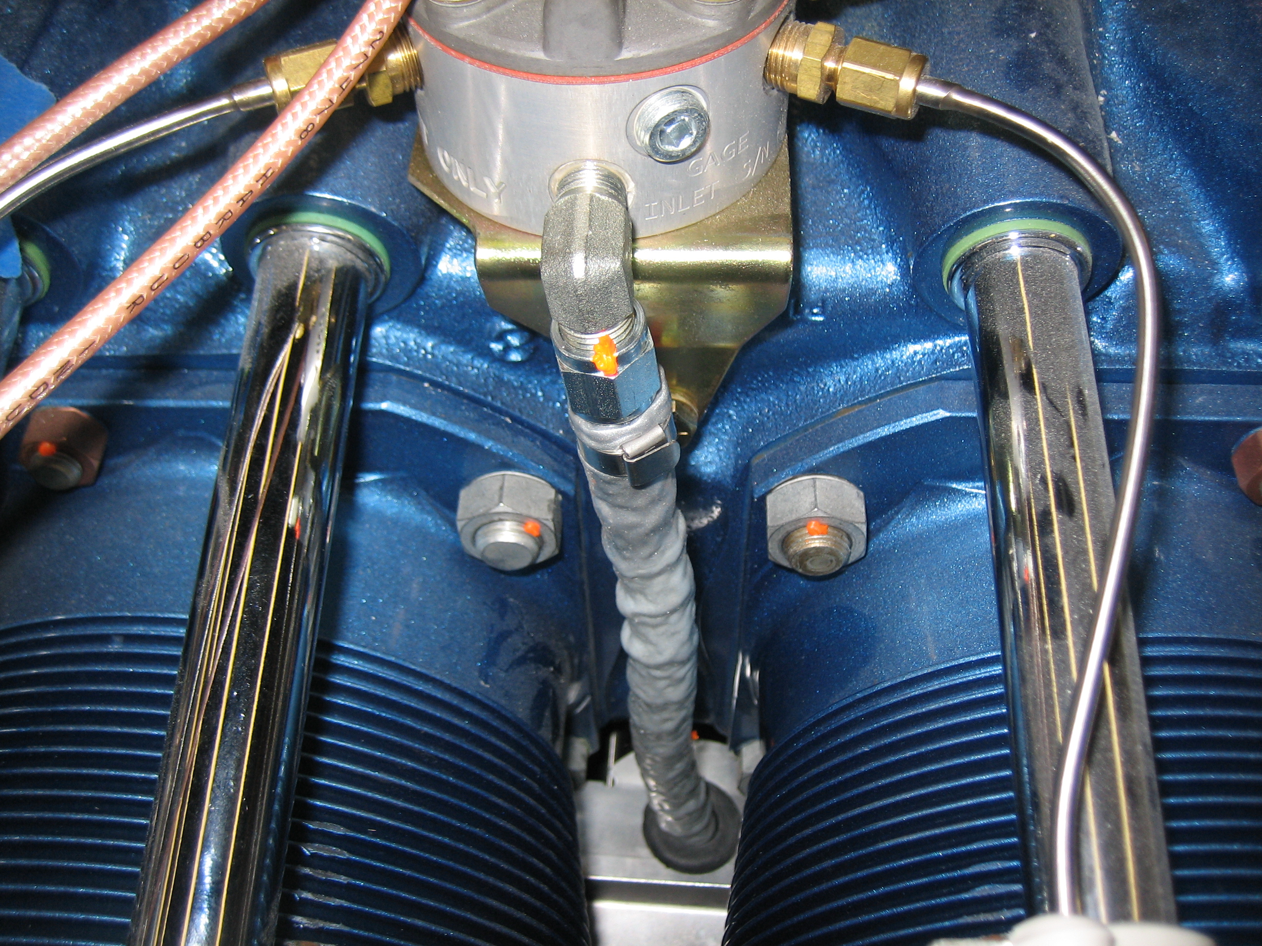
I then installed the short fuel line between the fuel servo and the fuel flow sensor. If you want to duplicate my setup, you’ll need a 2.75″ seat-to-seat hose with 1/4″ straight-to-straight connectors and firesleeve.
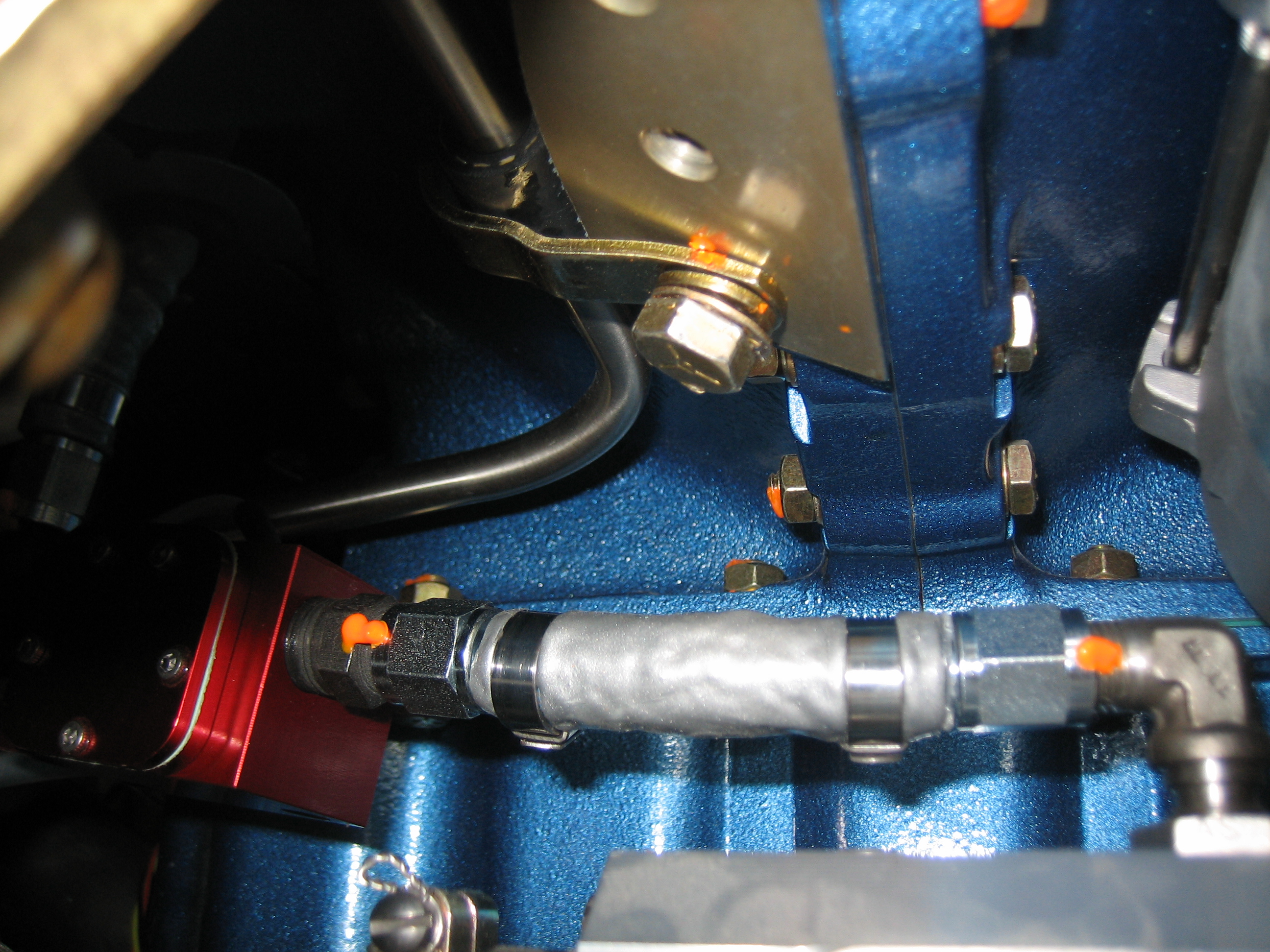
The output side of the sensor has an identical fuel line, but 9.75″ seat-to-seat. It’s a little hard to tell from this picture, but there’s quite a lot of clearance all around the sensor. It’s only about 3″ from the #1 exhaust pipe though. The alternator wire is a little closer even. I’ll put a long heat shield along this section of the exhaust pipe to reduce radiated heat to these components.
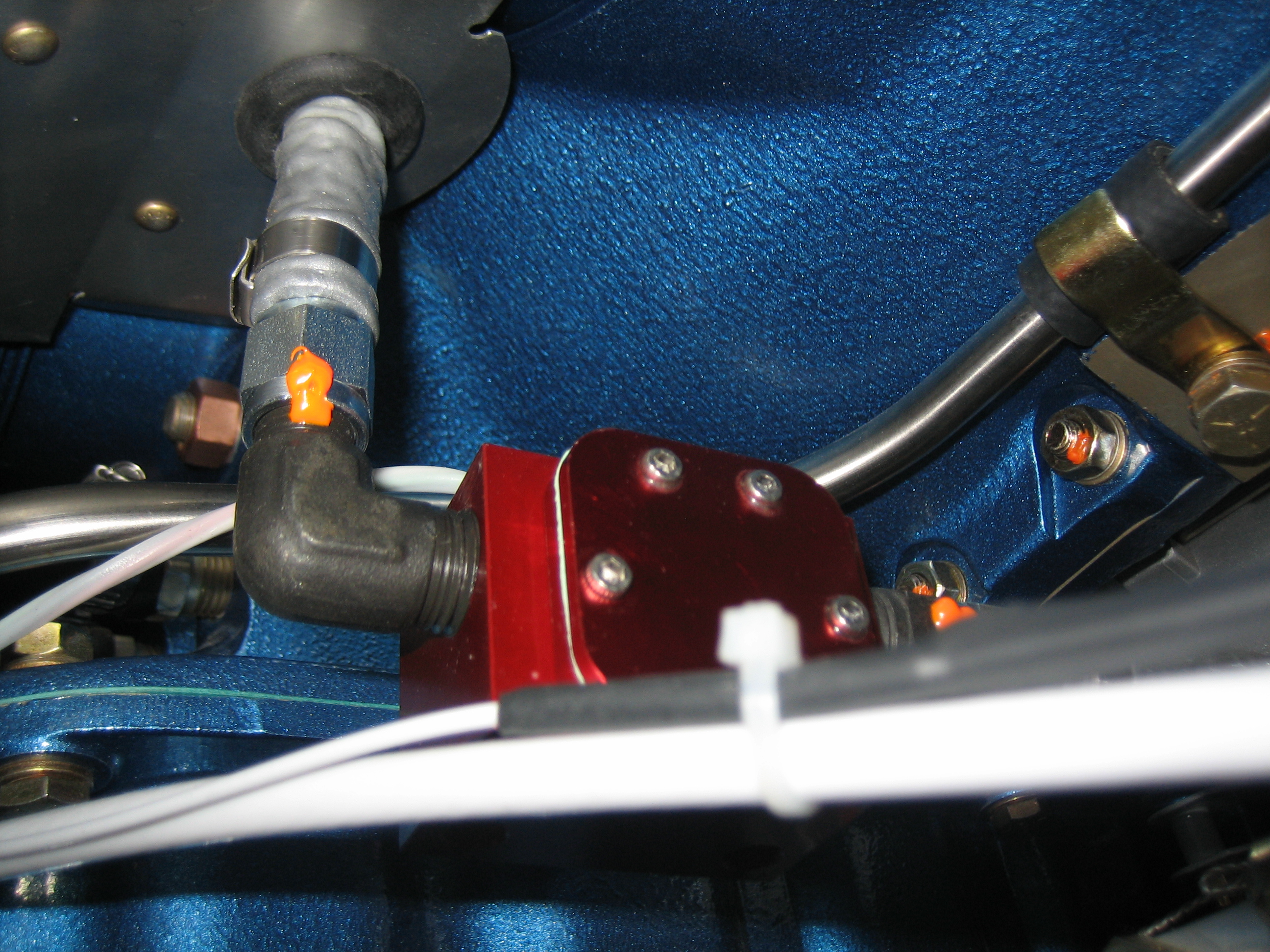
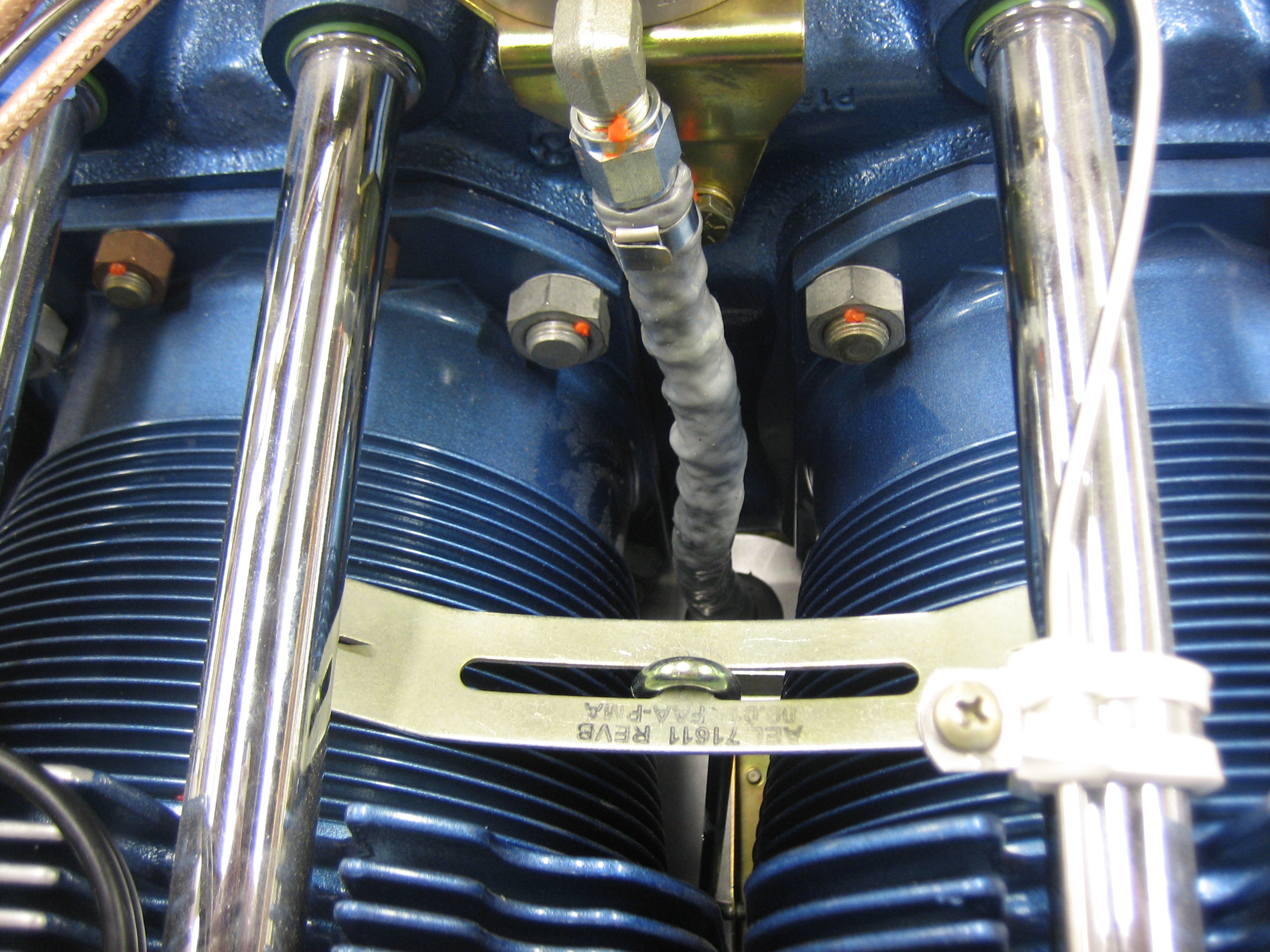
Here you can see how the fuel hose makes a straight run up to the spider from there.
I then reinstalled the inter-cylinder baffle retaining clamp (which was a pain in the ass).
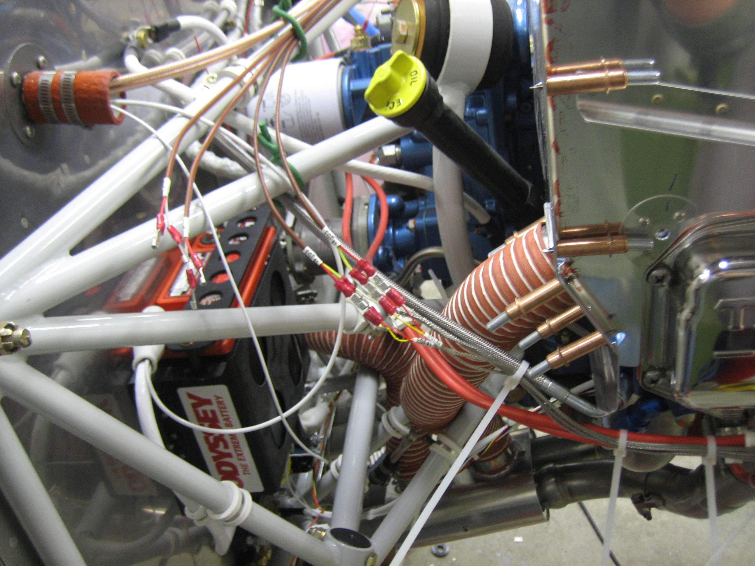
I’m also using the knife connectors to connect the EGT/CHT wires to the EMS harness. I got through part of the connectors on the right side tonight.
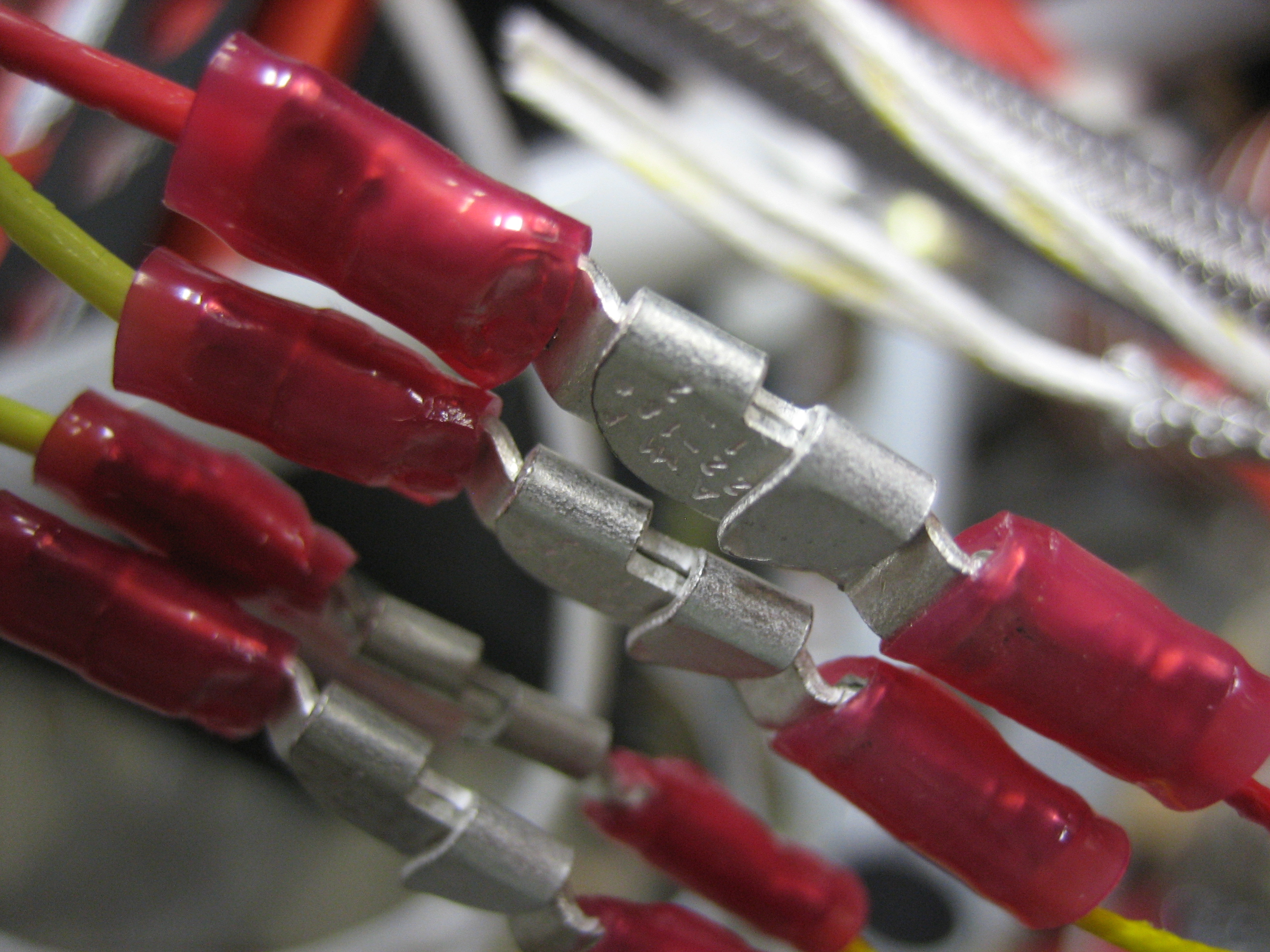
Here’s a closeup of the #1 and #3 EGT connections.
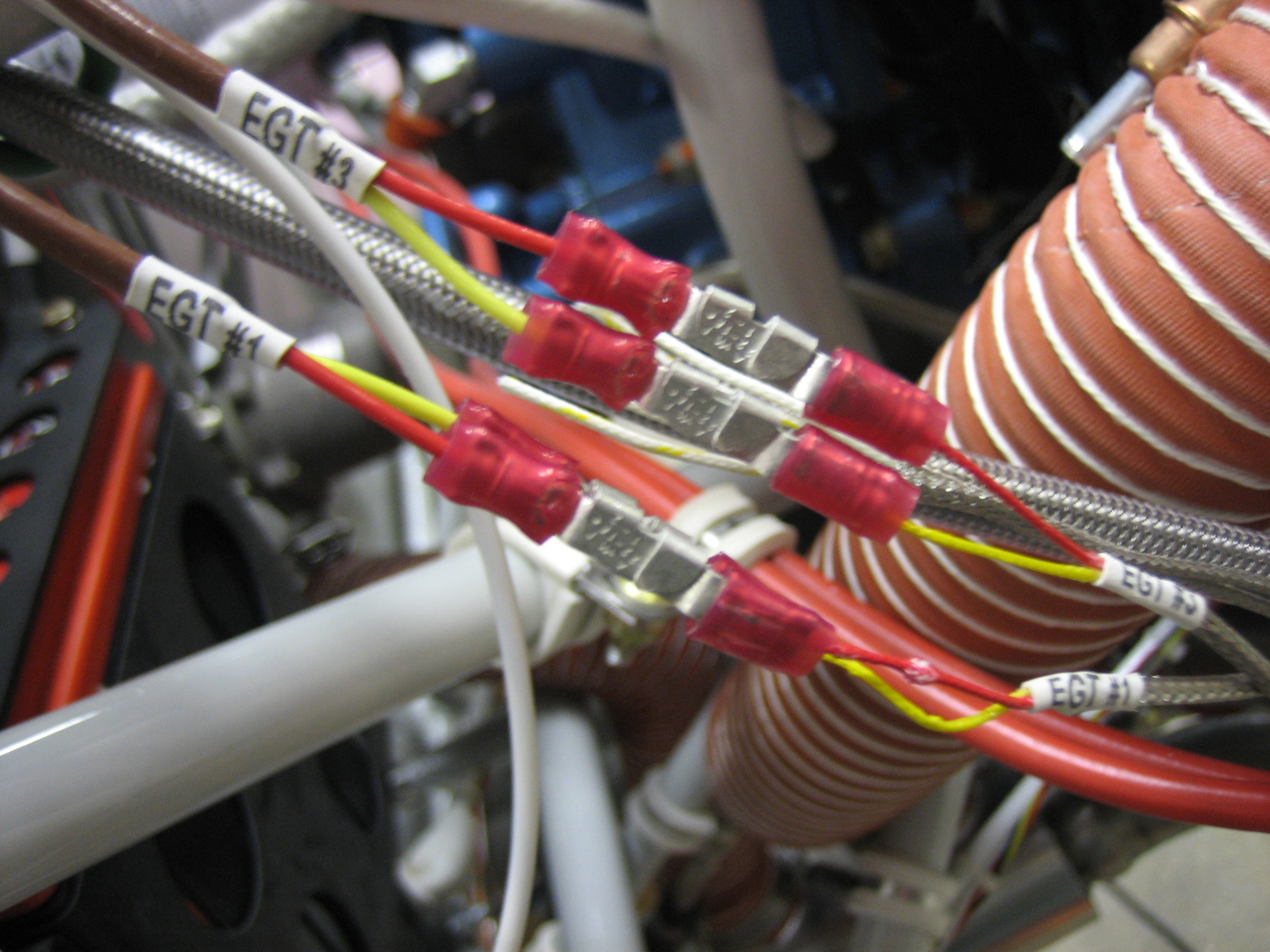
The knife connectors interlock and form a connection that can’t vibrate apart even under tension. I’ll put sections of heat shrink over all of these connections before finishing off the wiring bundle.