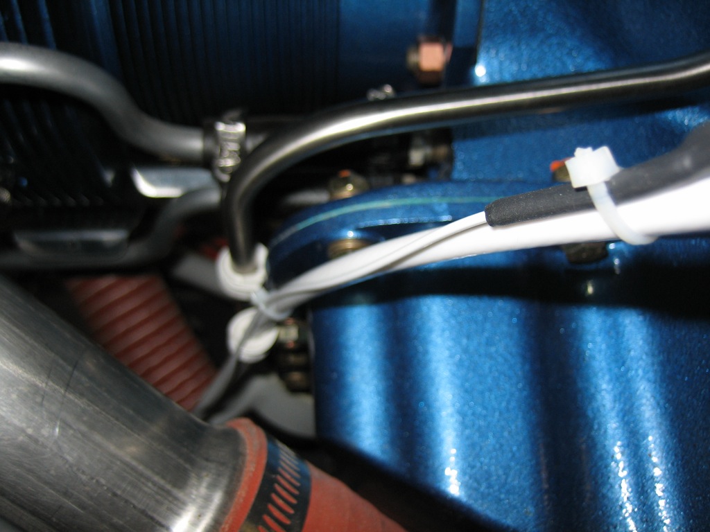
I zip-tied the EGT and CHT wires to the ignition wires on both sides. These are just temporary, but I need to get the wires in their final positions so that I can begin cutting things to length.

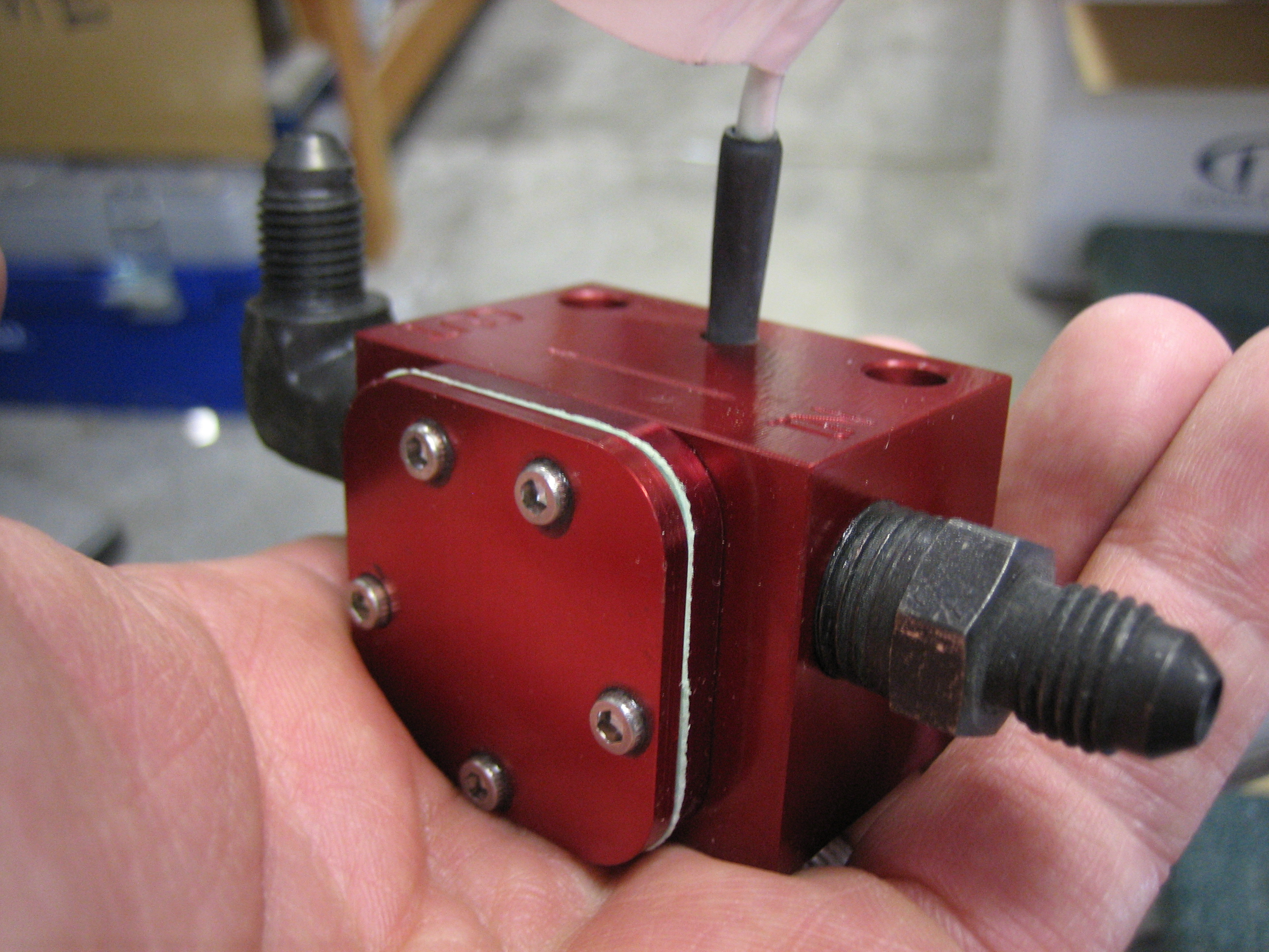
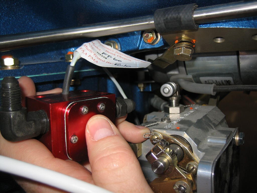
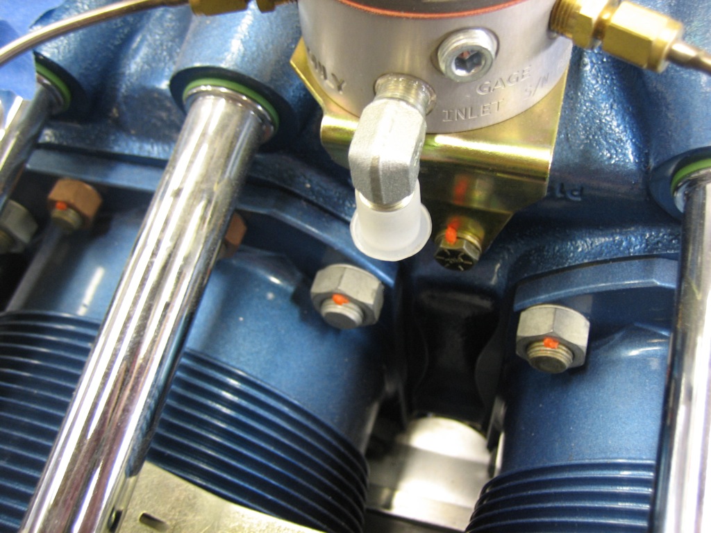
I then installed the 1/4″ nipples into the EI FT-60 (colloquially known as the “red cube”). This will be mounted between the fuel injection servo and the spider and will measure the fuel that’s being delivered to the engine.

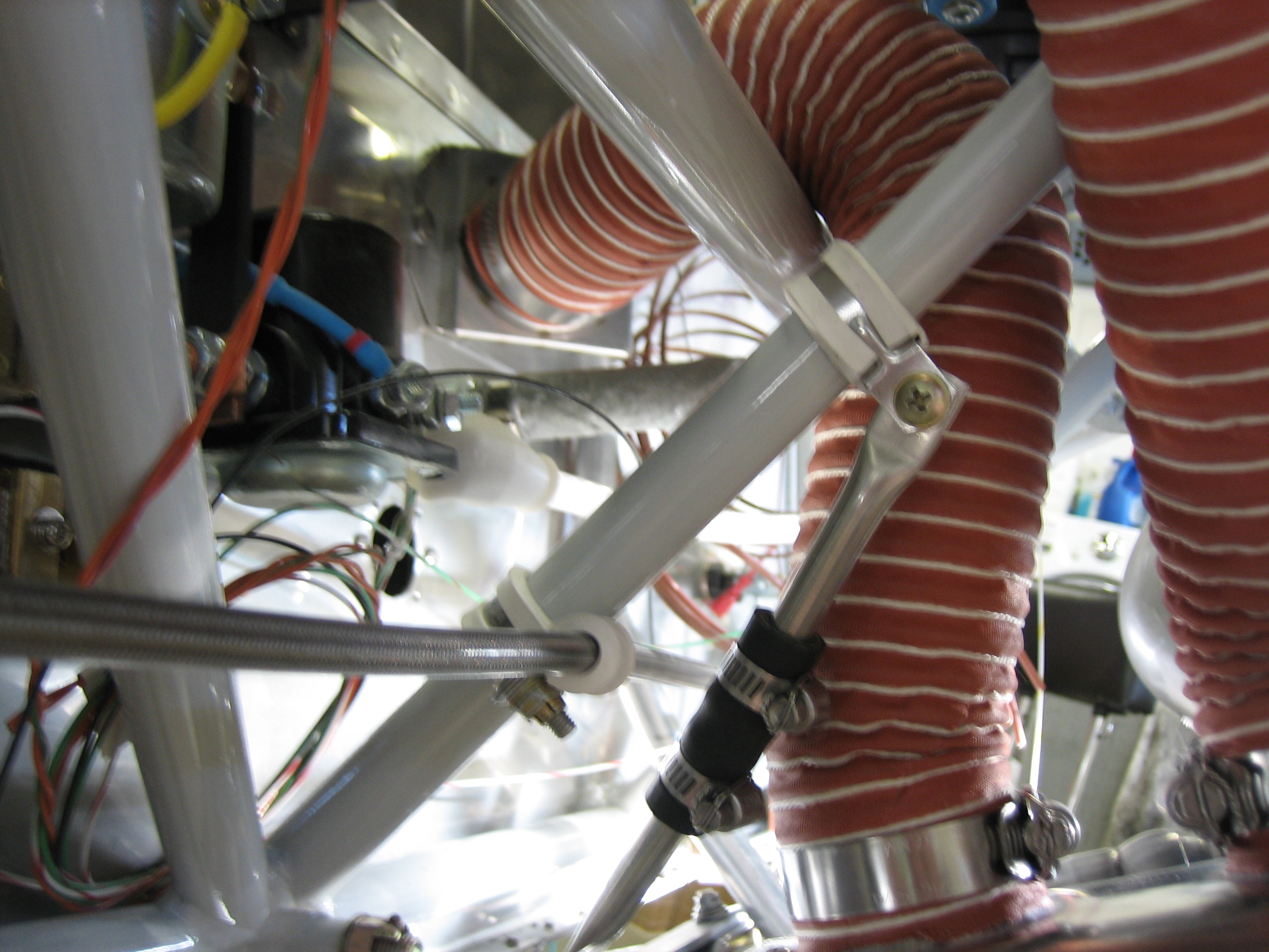
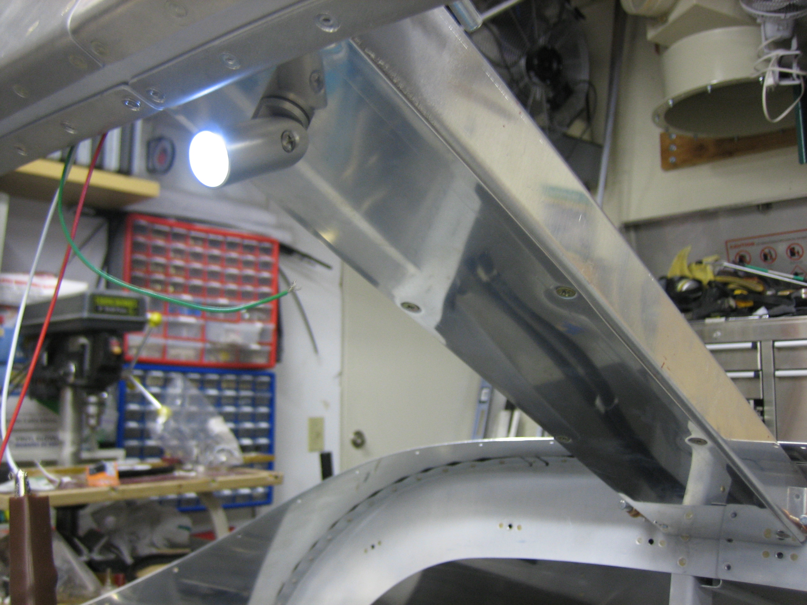
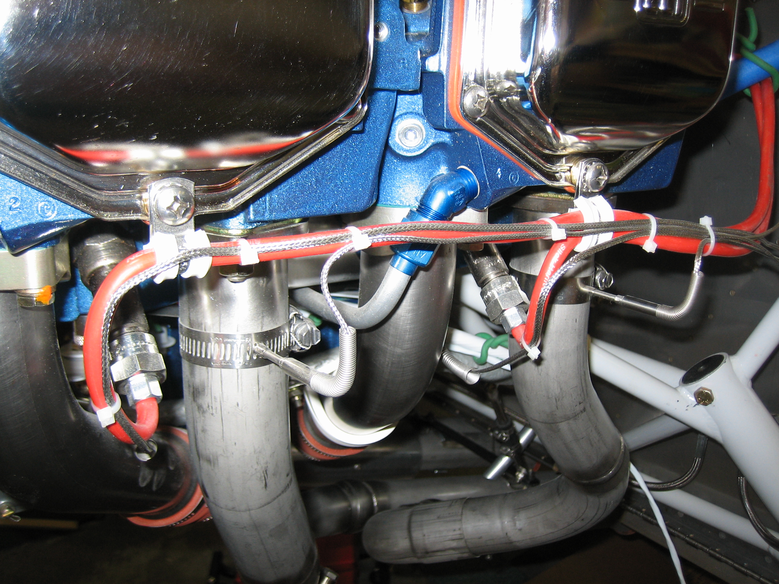
Here’s roughly where it will be installed. I will need a 2 3/4″ hose that connects the fuel servo to the input side of the red cube. Hopefully Bonaco can make one this short.
The output side of the cube has a 90º elbow that points directly at the inner end of the right-side inter-cylinder baffle. I’ll drill a hole through there to pass the hose that connects the red cube to the spider.
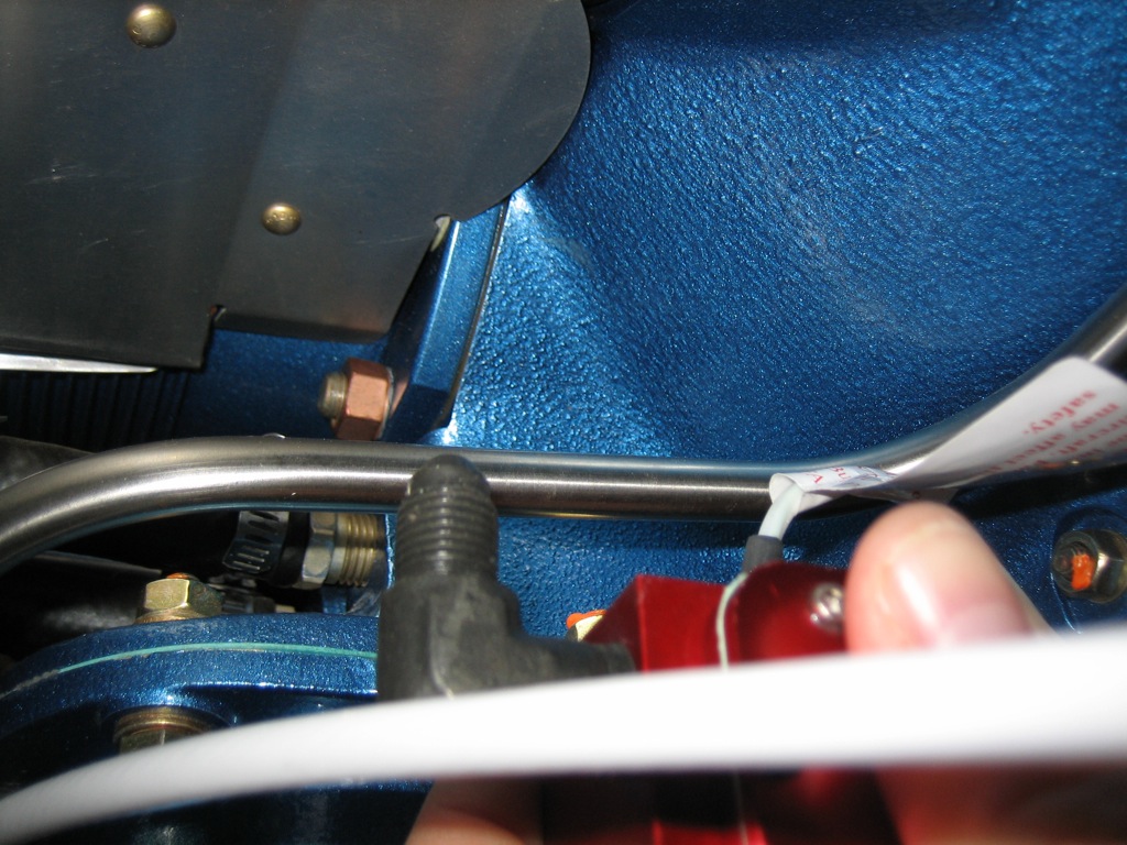
I also removed, re-lubed, and reinstalled the fitting in the spider so that it points straight down. The shiny area between the cylinders is the inner cylinder baffle where the hole will be drilled.
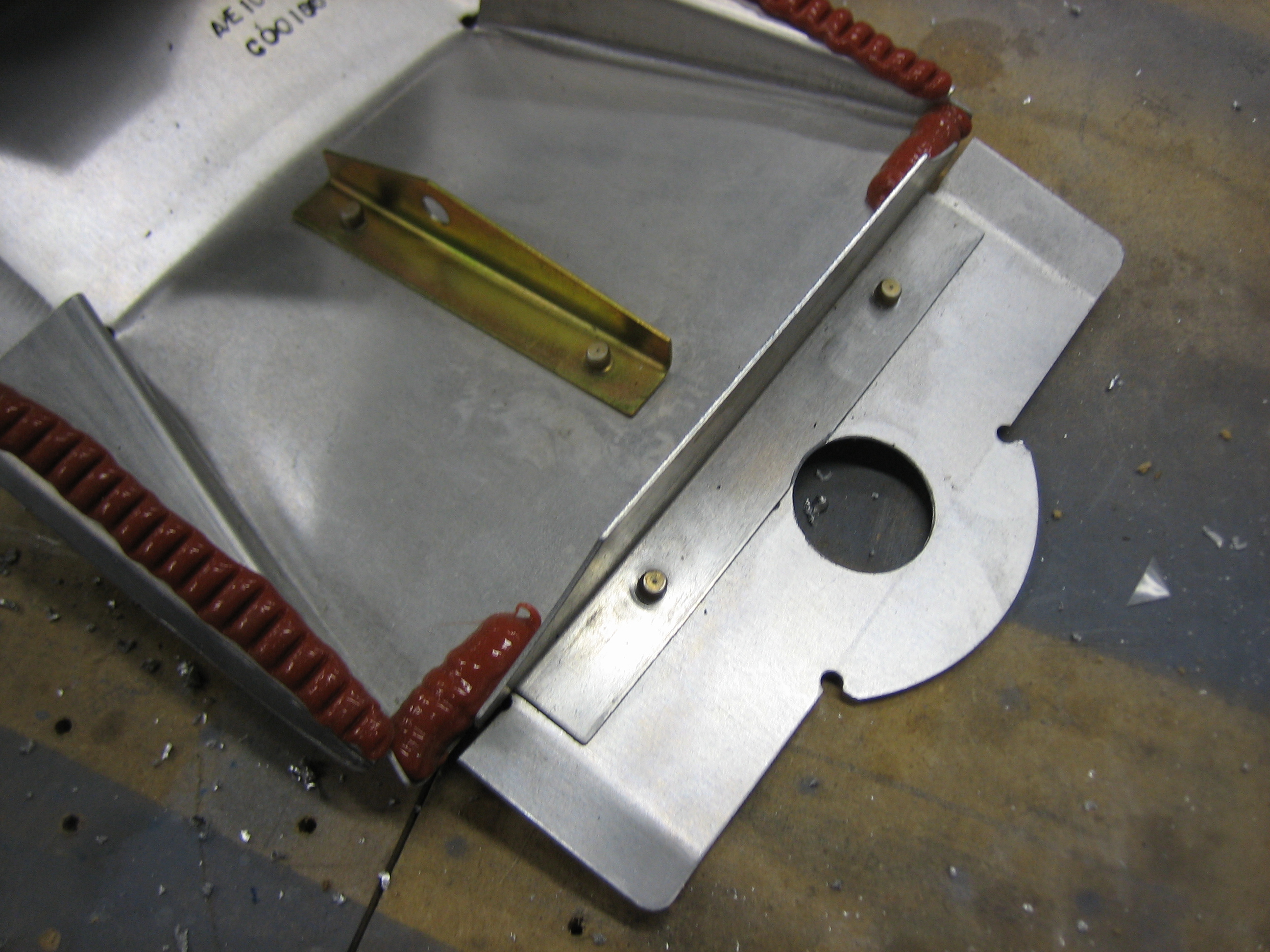
I removed the right side inter-cylinder baffle so that I could drill the hole.
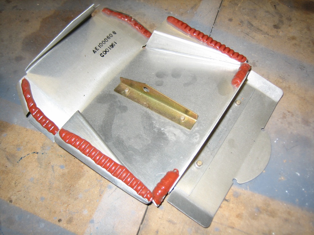
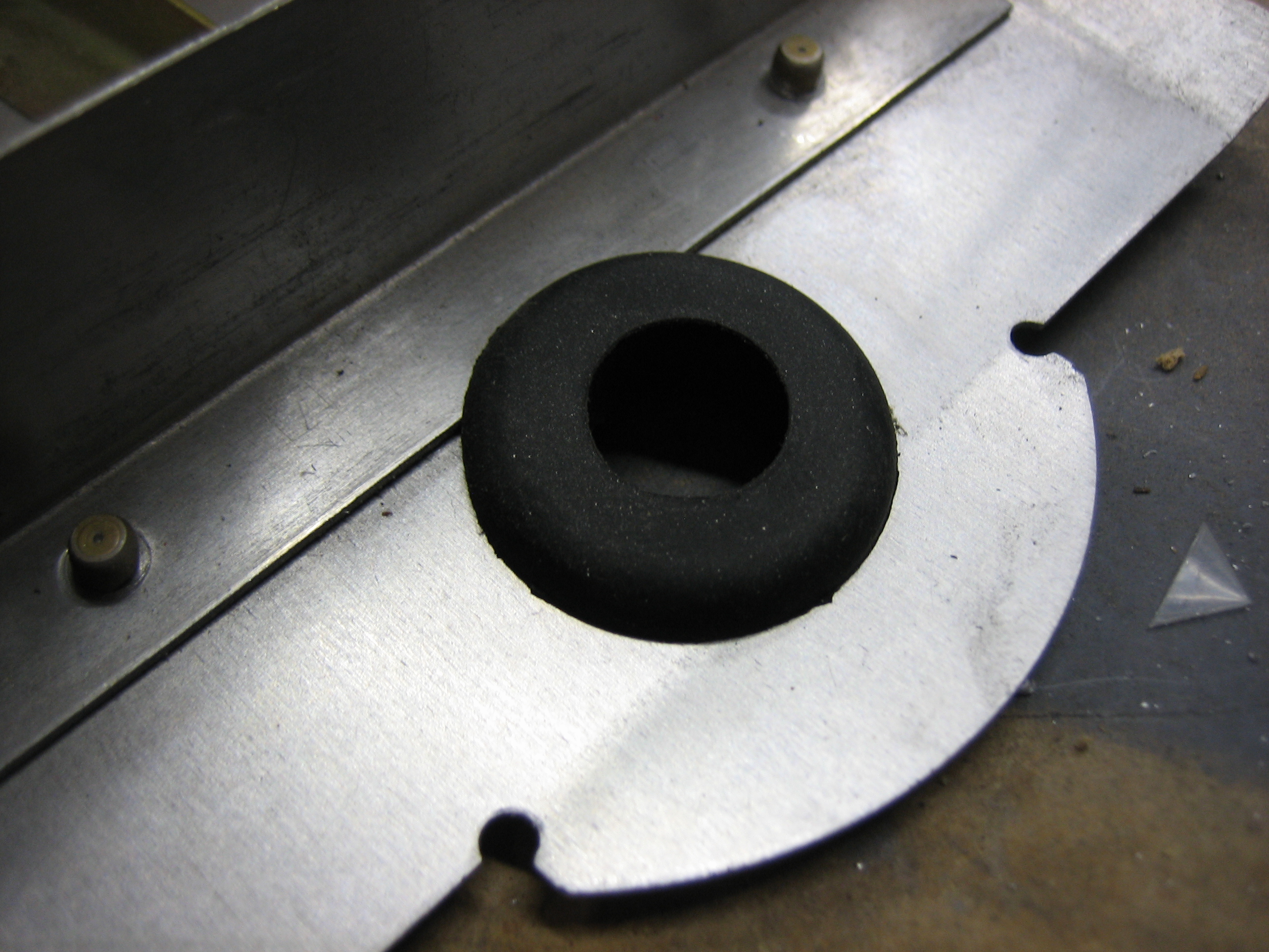
I drilled a 13/16″ hole…
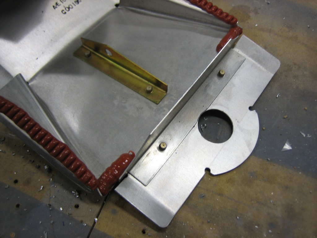
…that will hold a grommet that has a 1/2″ interior hole. That is roughly the outside diameter of a 1/4″ hose with firesleeve. I’ll have to install the grommet over the hose before installing it in the hole, but I wanted to make sure it fits properly.

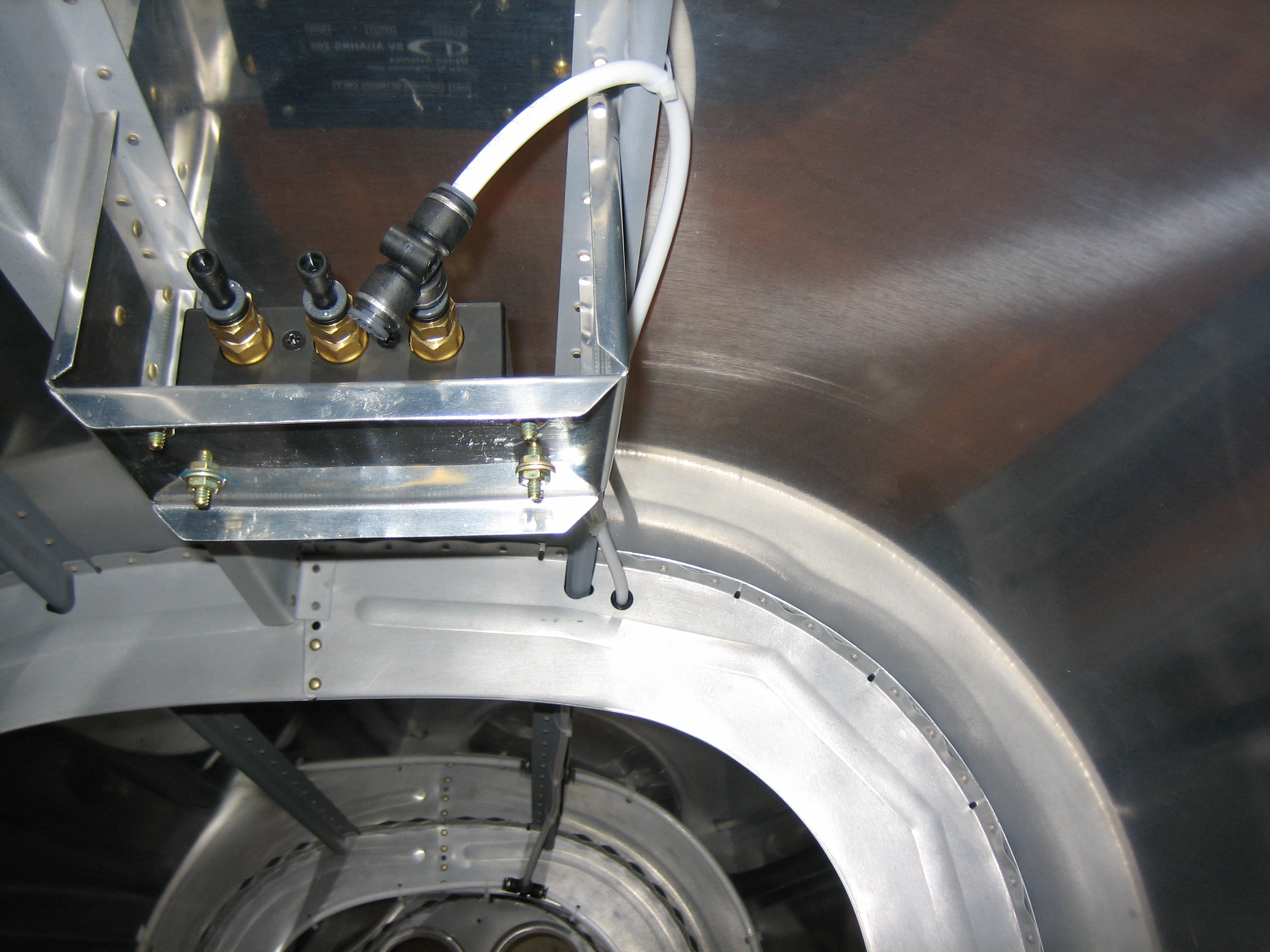
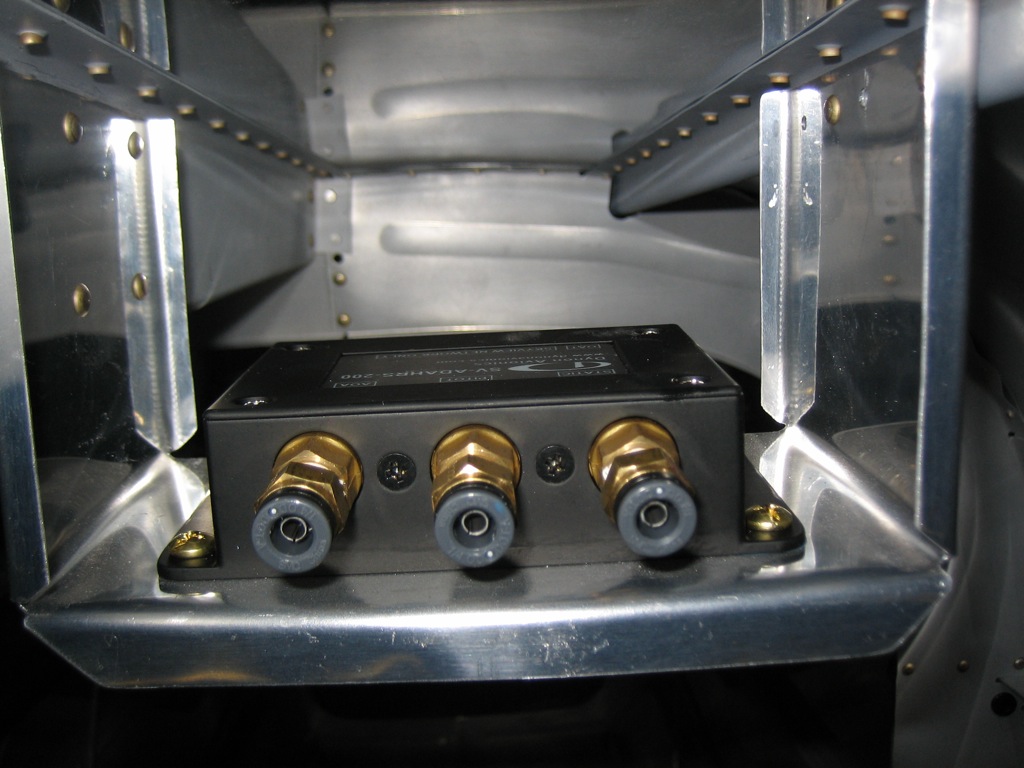
I stopped by OSH and picked up some #10 brass hardware and installed the SkyView ADAHRS. The ADAHRS contains a magnetometer, so there can’t be any ferrous metal near it so that it can get an accurate heading reference.
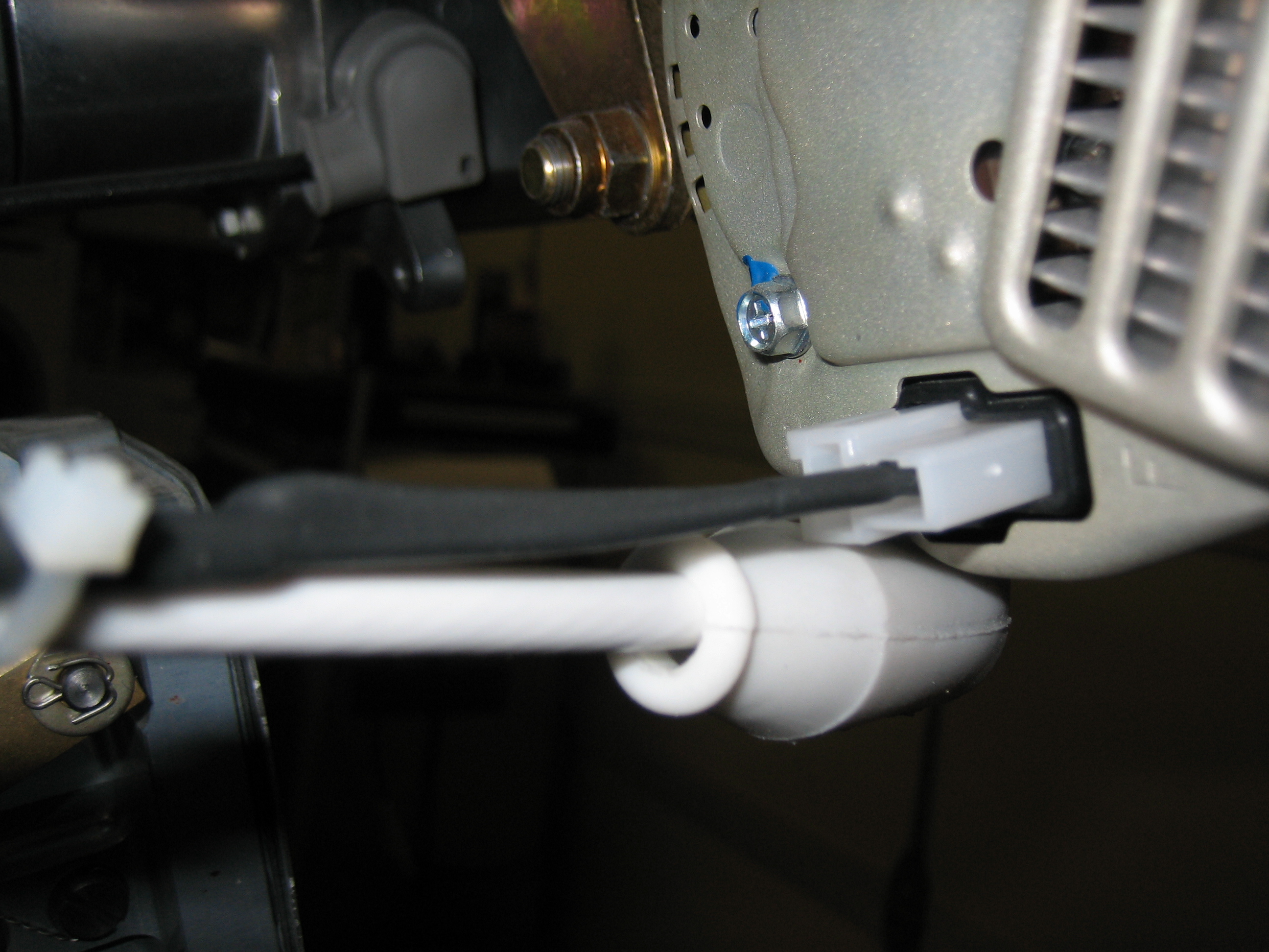
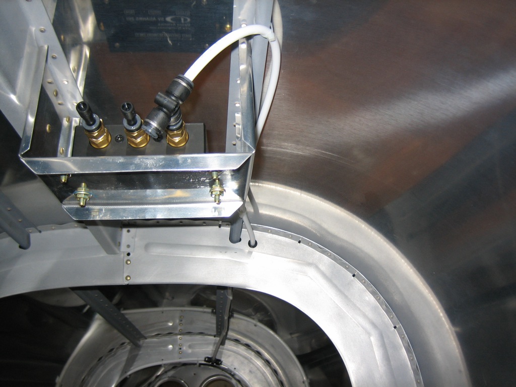
I crawled back in the tailcone (hopefully for the last time) to install the static tubing from the tee on F-708 (near the bottom of the picture) through F-707 and into the front of the ADAHRS. There is a tee installed here because the static line will also run forward to the TruTrak Gemini that I’m using as a backup EFIS.
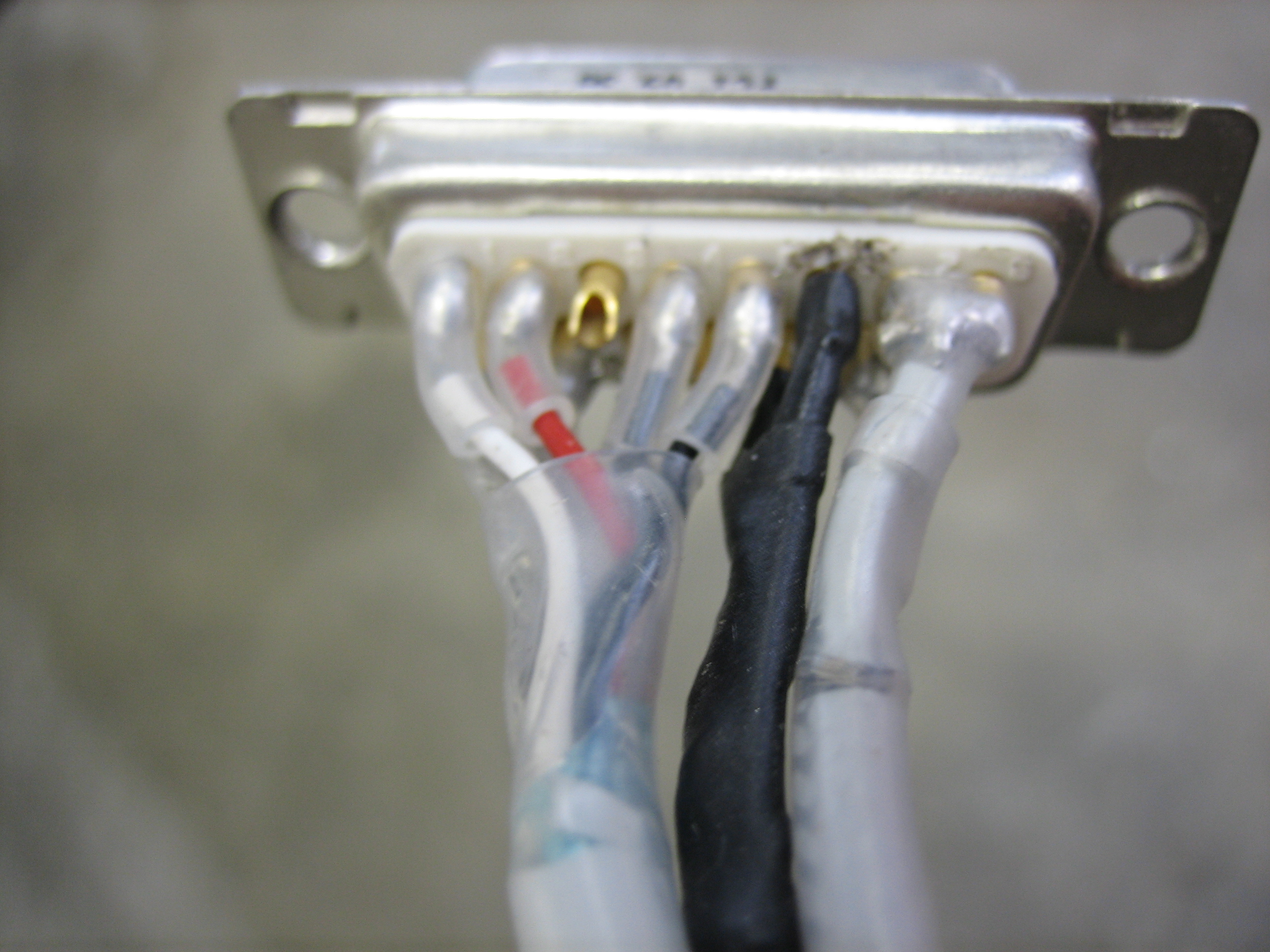
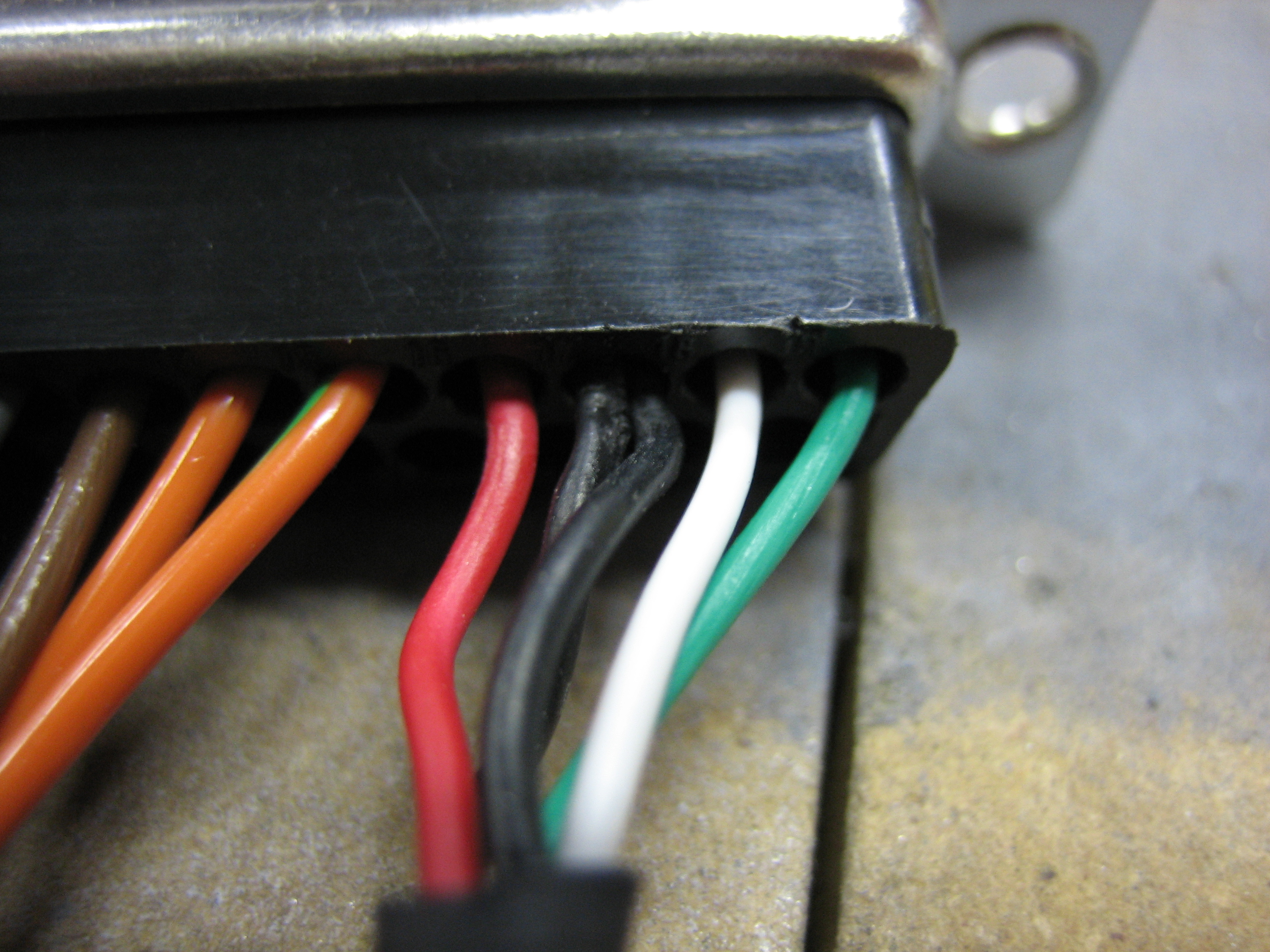
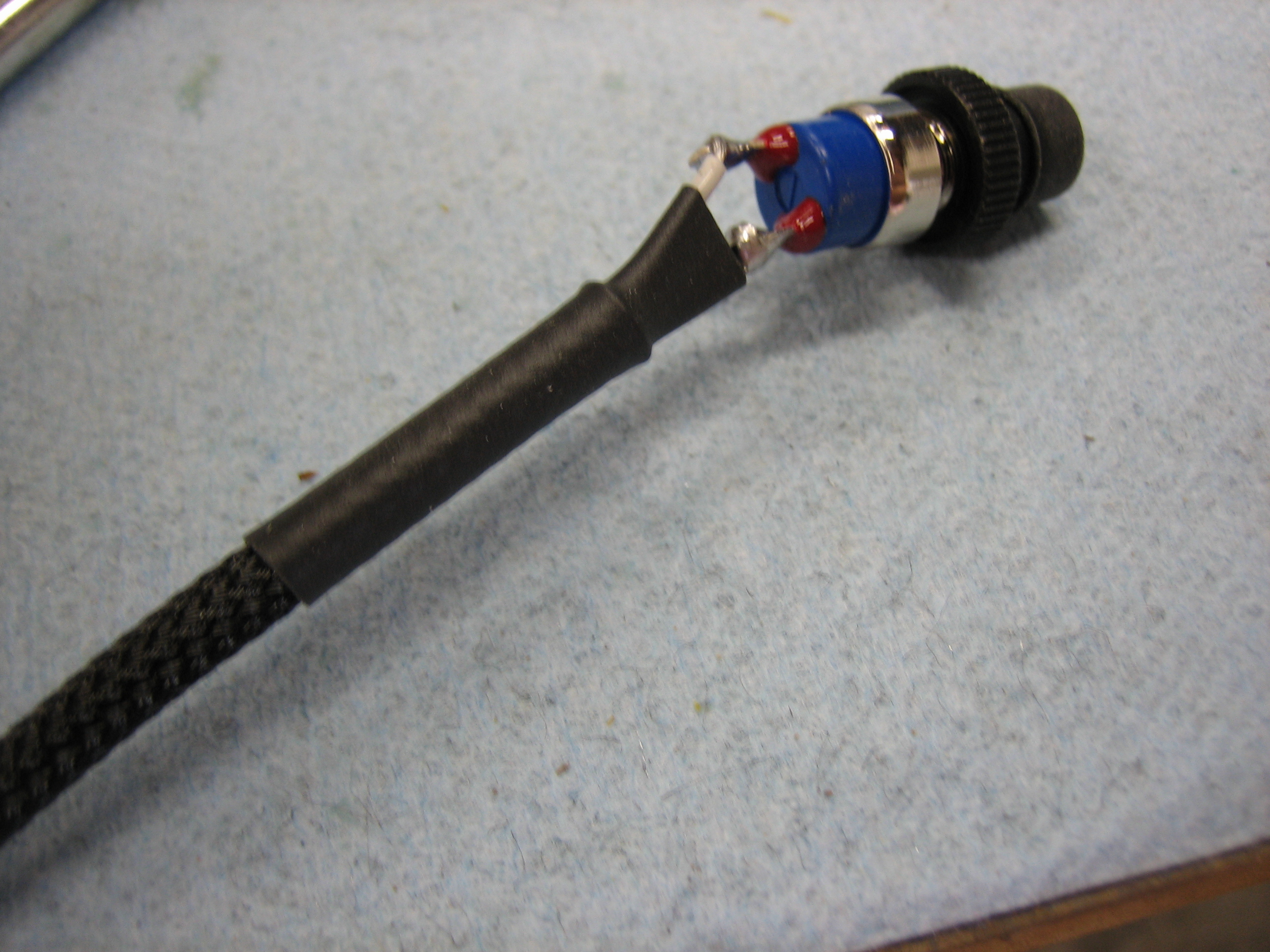
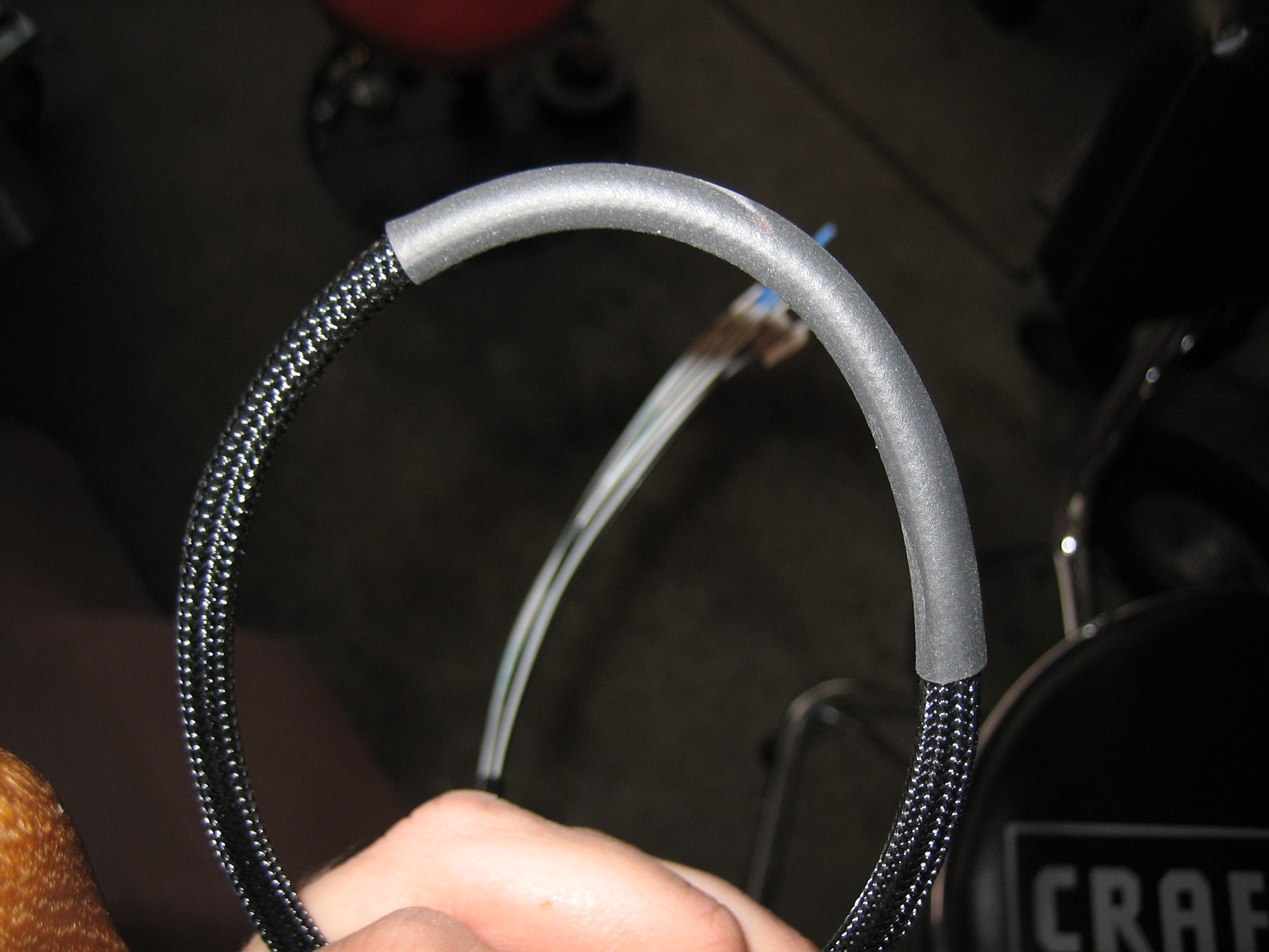
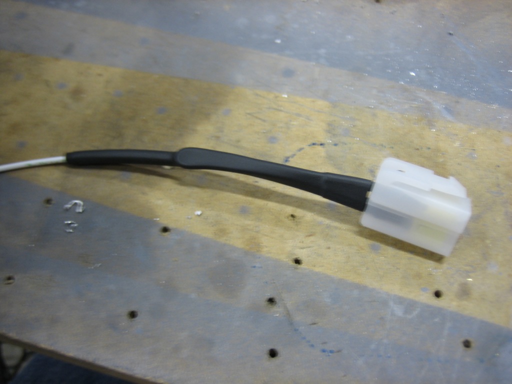
One of the things I got in my last order from B&C is the alternator field connector. I installed a jumper between the terminals and added some heat shrink.
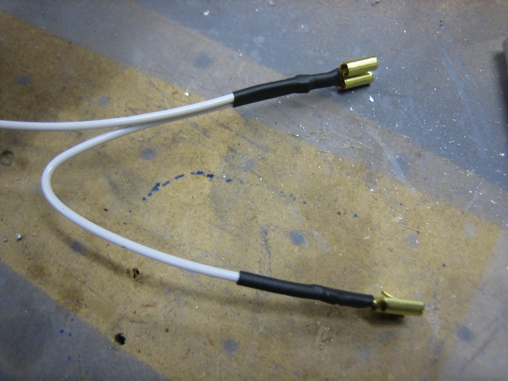
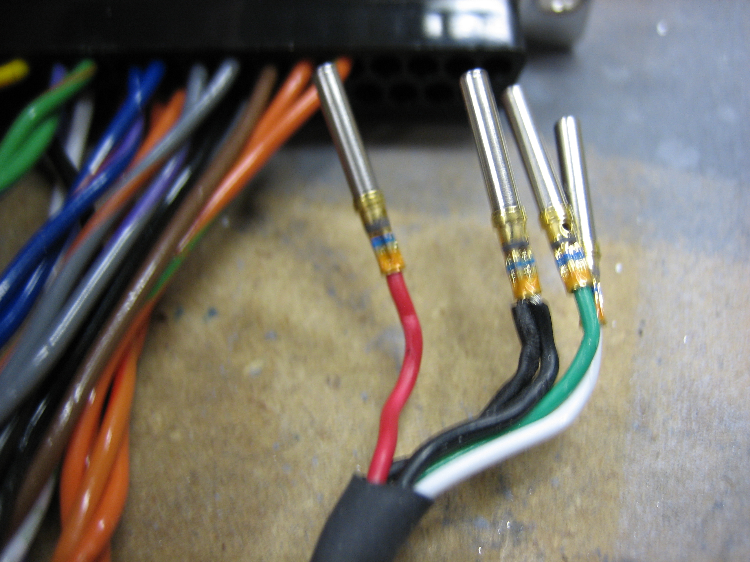
I added a couple of extra pieces to build up the thickness of the single wire.
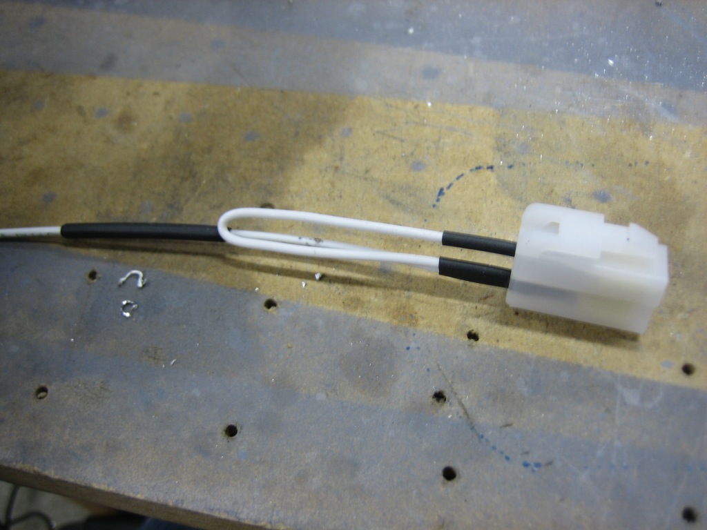
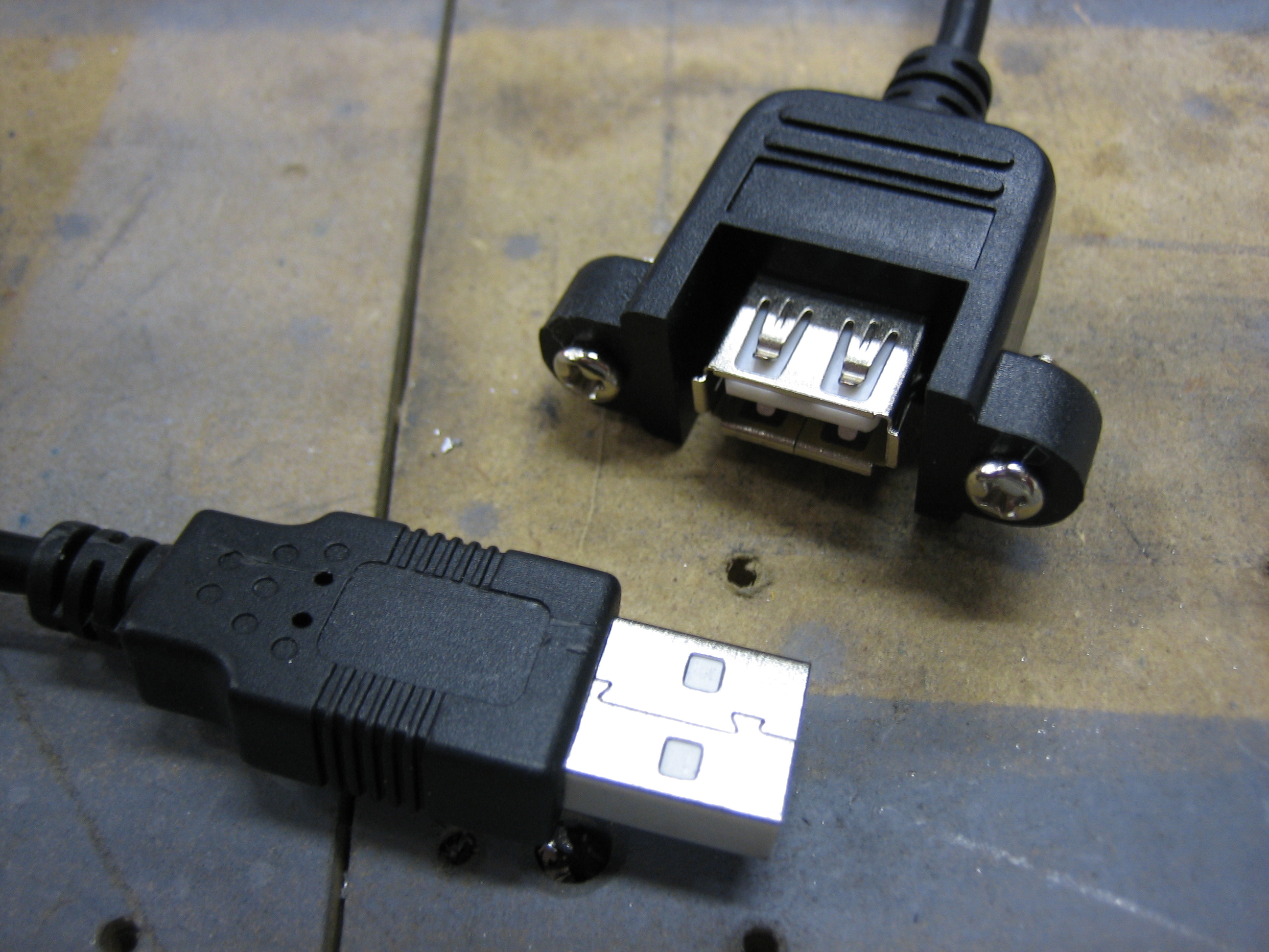
Then installed a larger piece of heat shrink over the whole thing.
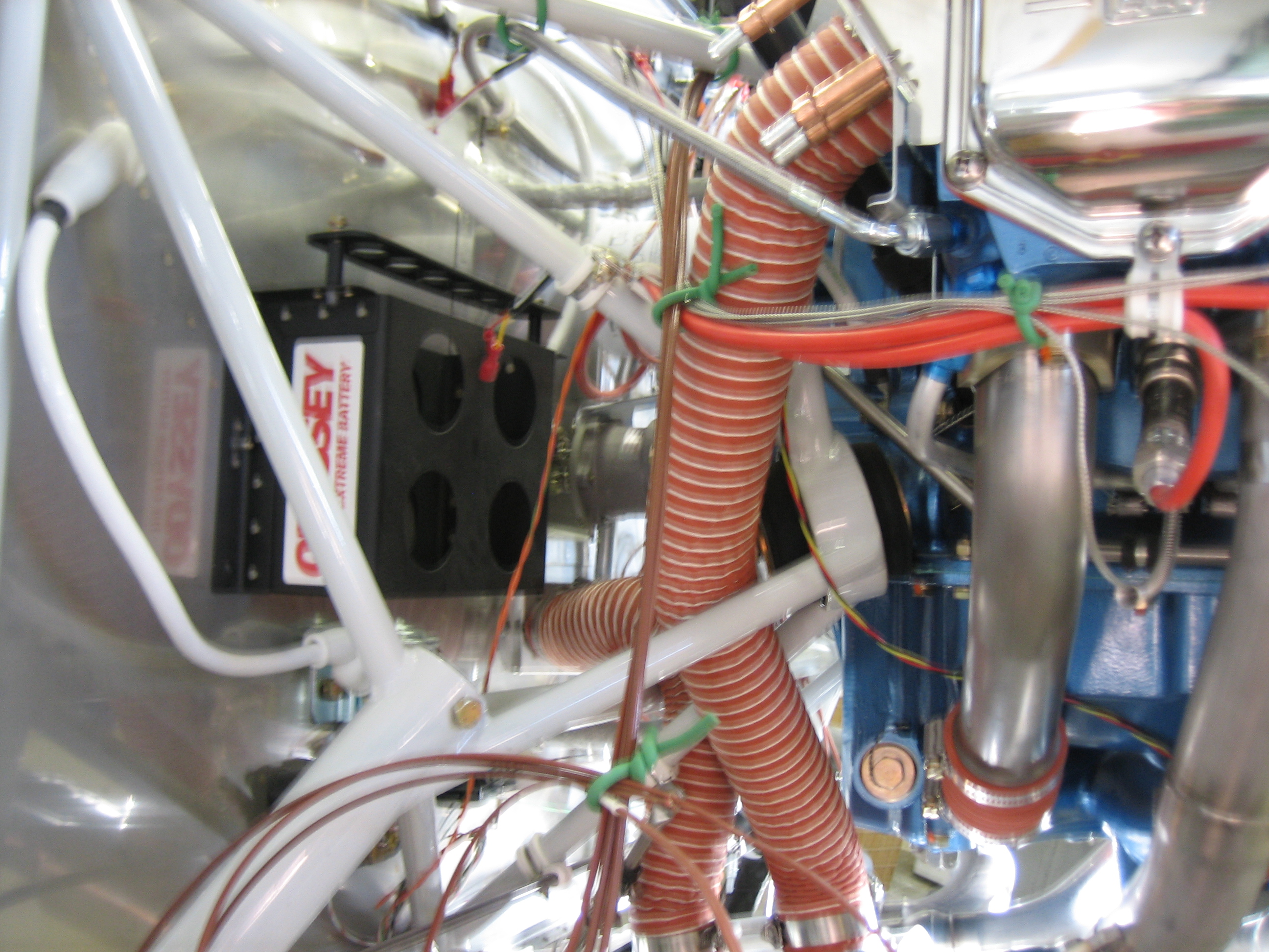
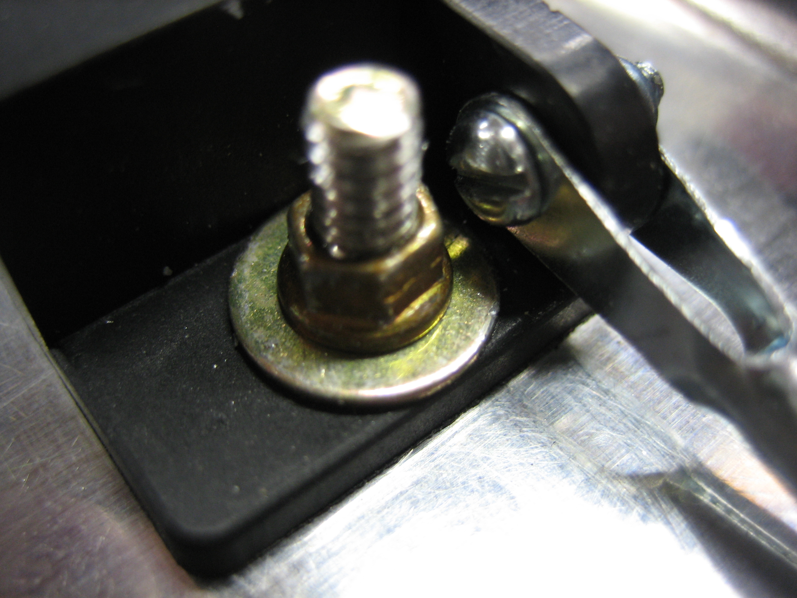
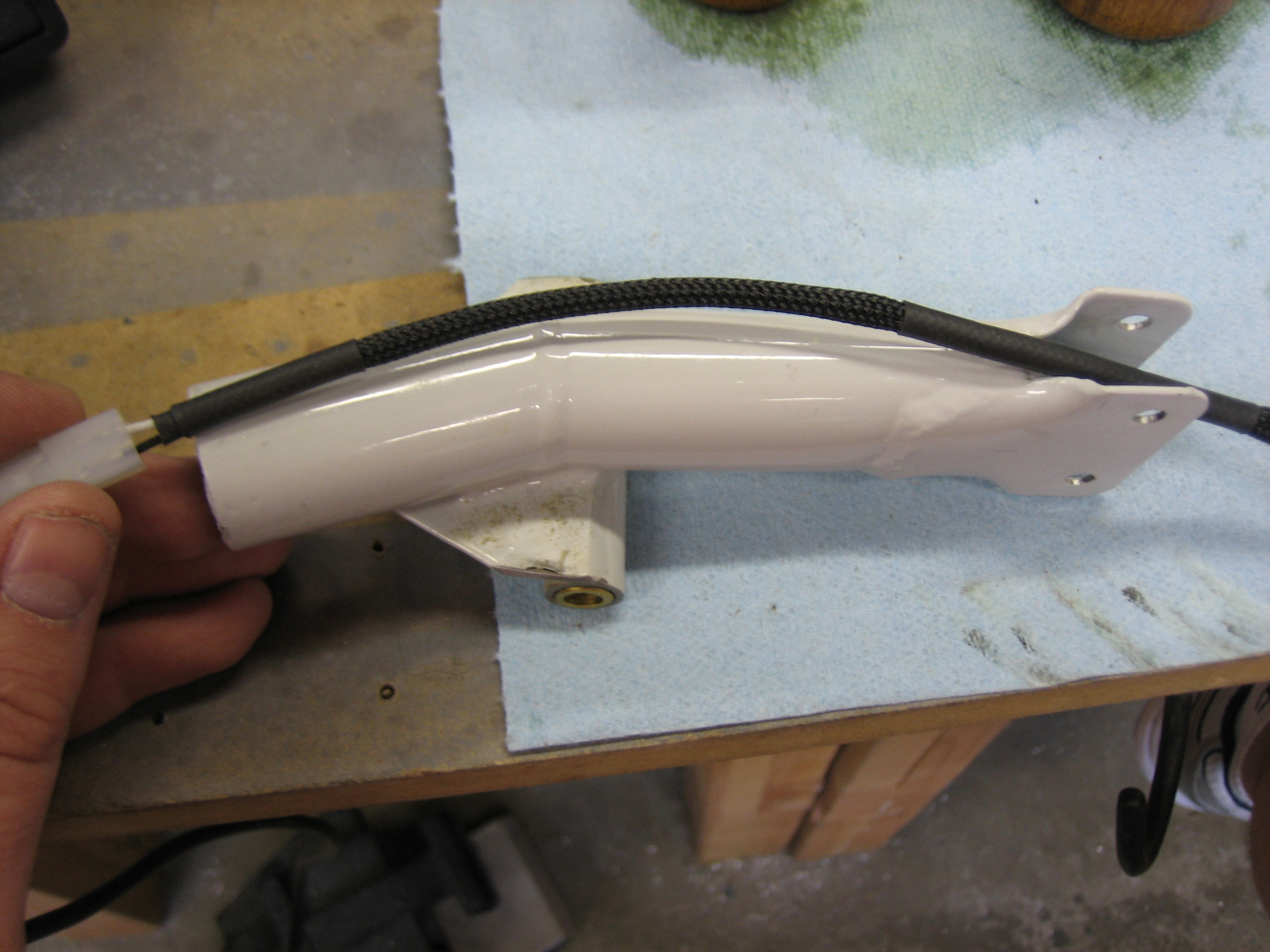
Here’s where it connects to the back of the alternator.
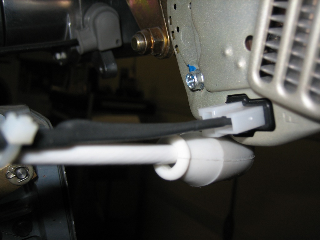
The wire will likely run along the alternator b lead along with the wires for the fuel flow sensor.