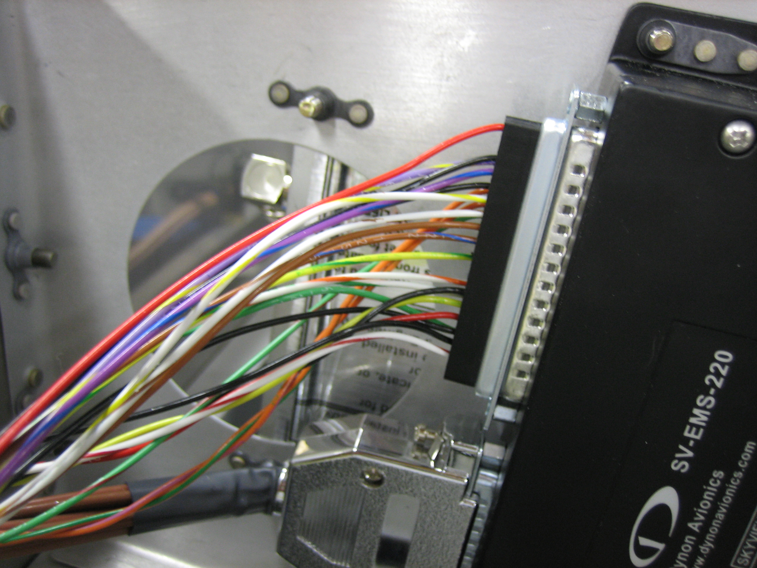
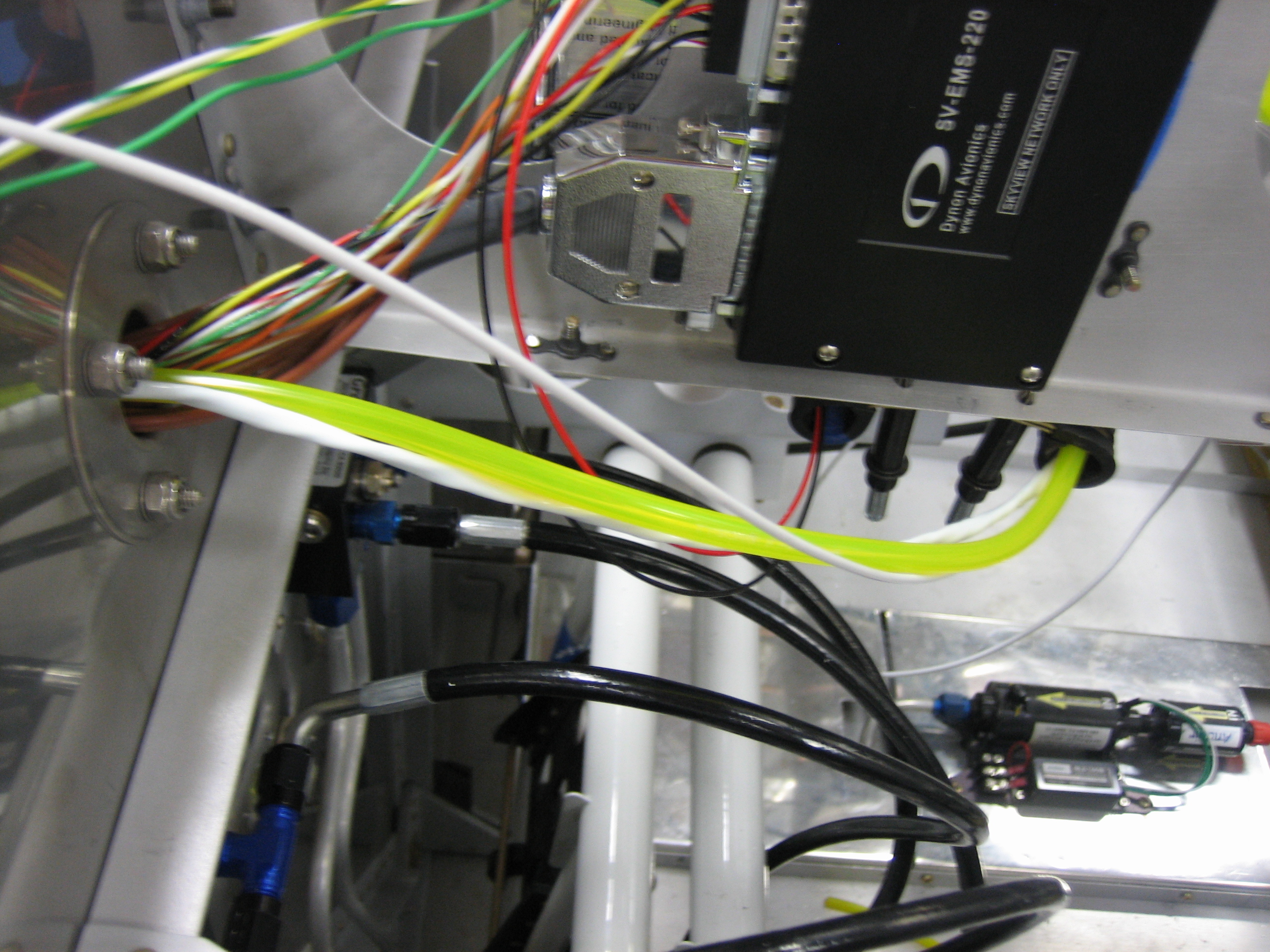
I removed all of the unused wires from DB-37 connector on the SkyView EMS. I ended up taking out a couple more after this picture was taken. This was a surprising amount of weight that I don’t have to haul around without benefit.
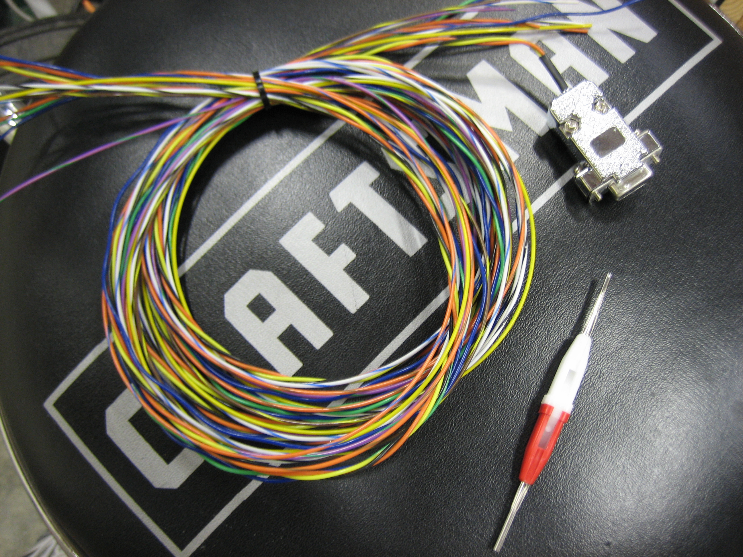
Here’s the remaining wires. I’m only using about half the pins in this connector now. Part of the reason is that all of the position sensors (aileron trim, elevator trim, and flaps) now connect to the VP-X.
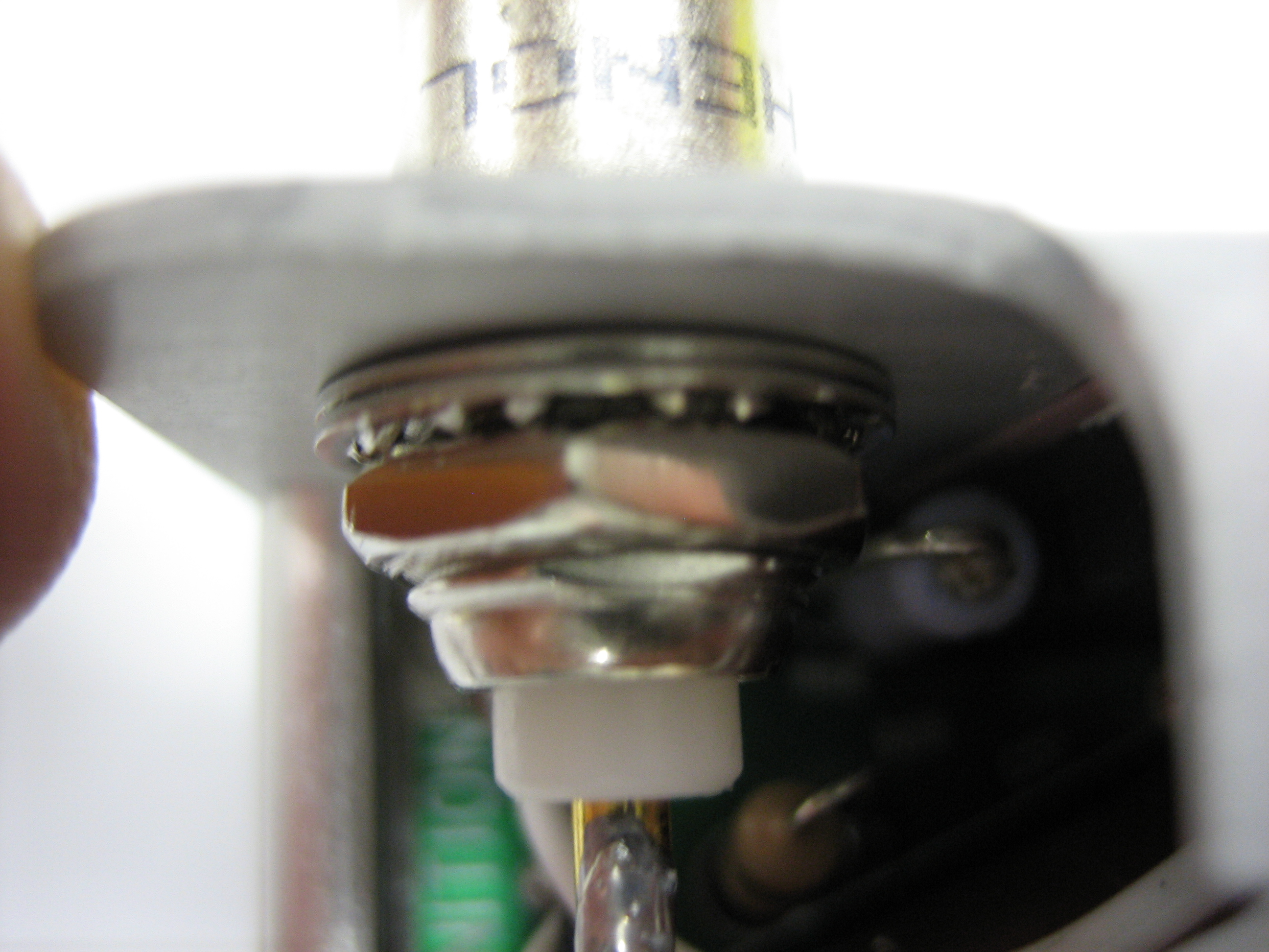
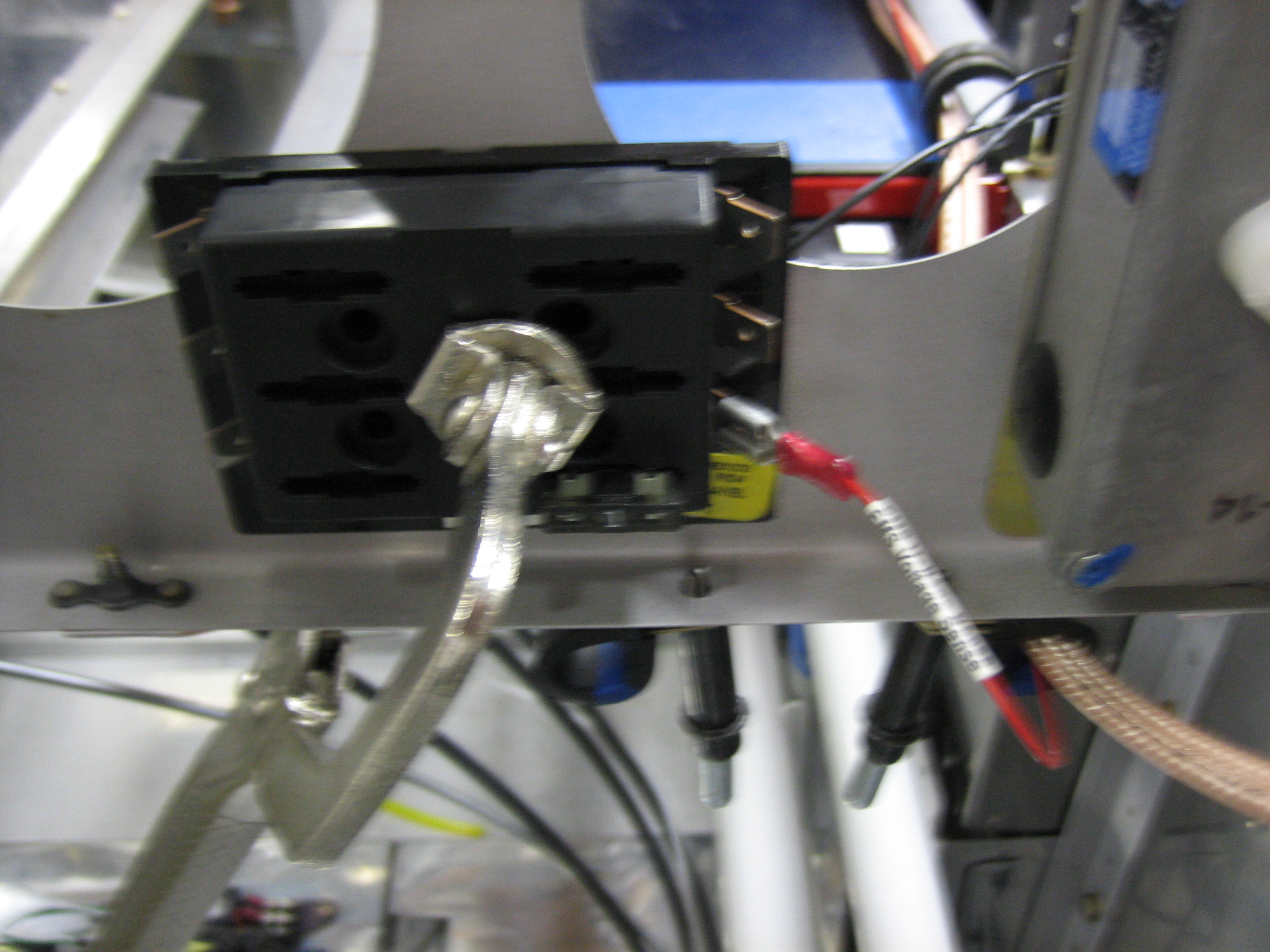
I noticed that one of the BNC connectors on the Light Speed ignition box was loose. I probably violated the warranty (which is likely expired now anyway), but I popped the cover off to tighten it up.
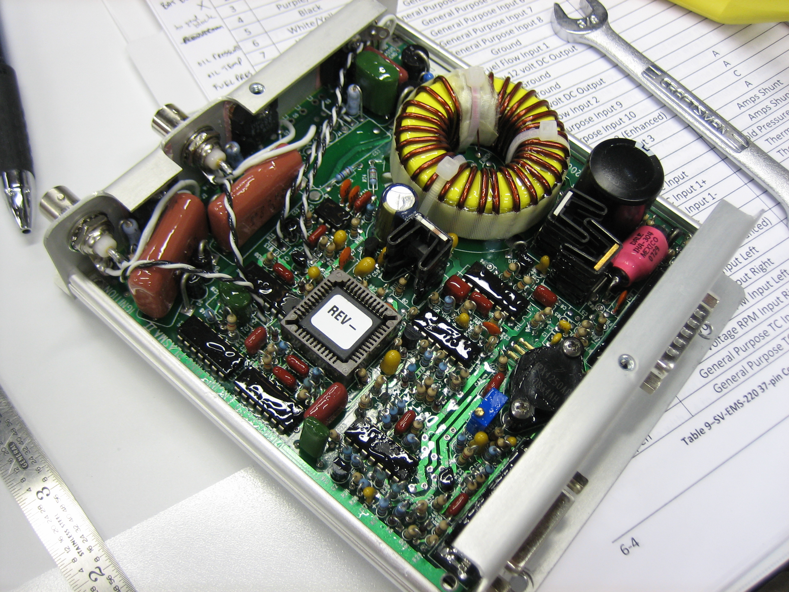
Here’s the connector in question. You can clearly see that the lock washer isn’t even compressed. They simply forgot to tighten it fully at the factory.
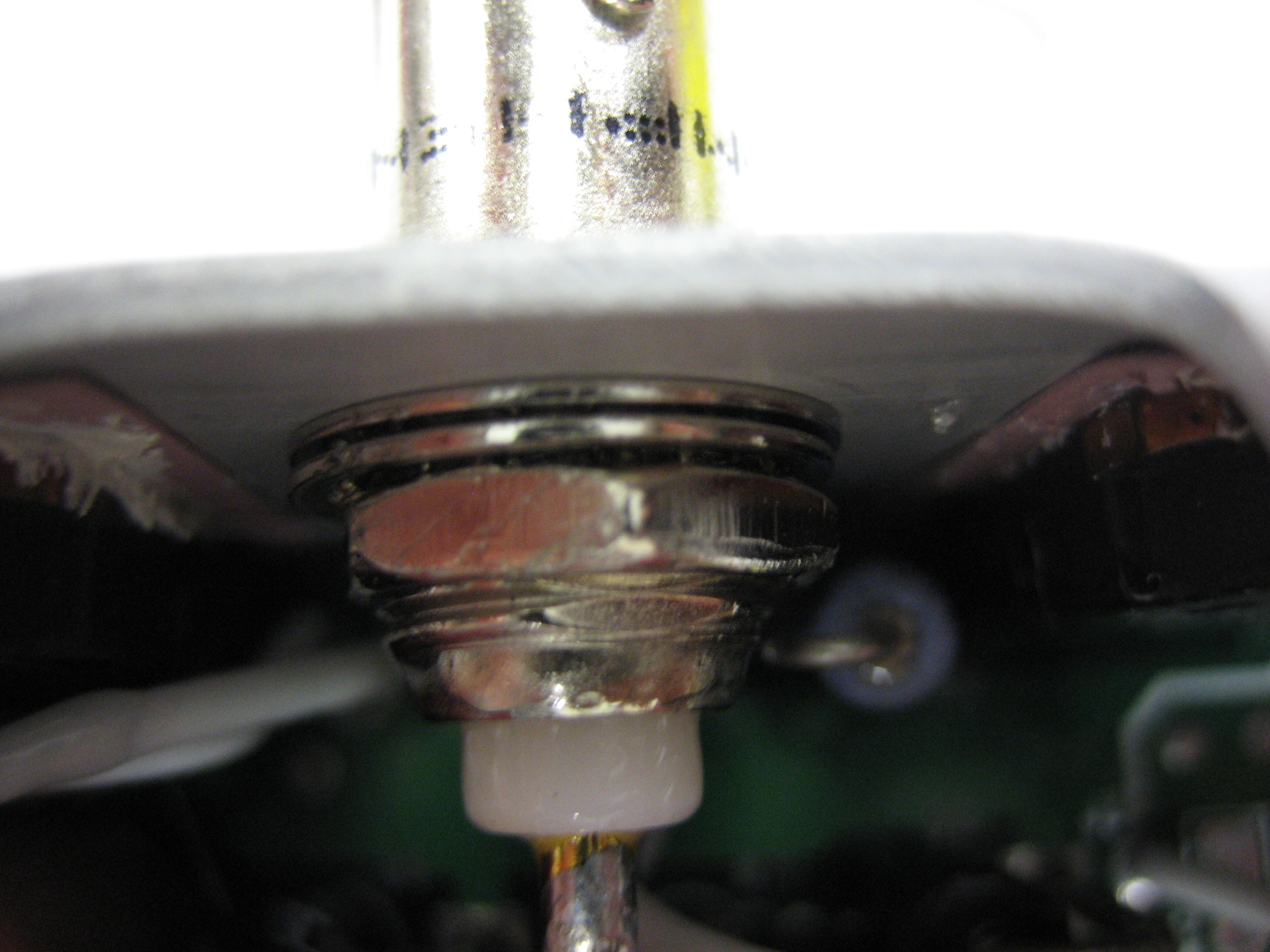
By comparison, the other BNC connector was tightened fully. Now they both look like this and are rock solid.
I decided to reroute the ignition sensor wire so that it takes a more direct route back toward the firewall. This also keeps the wire away from the snorkel (not yet installed).
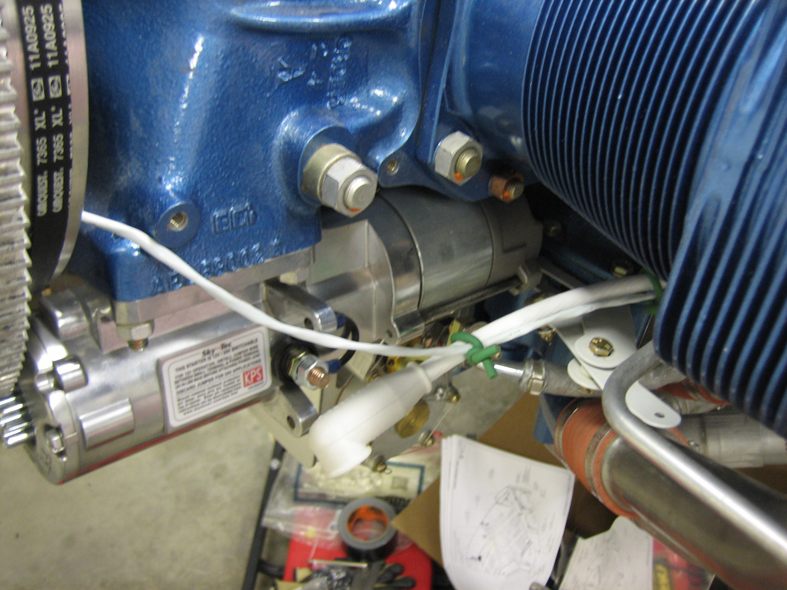
The wire follows the starter wire back to the engine mount then will get anchored where my finger is so that it will not interfere with the oil cooler.
It then turns up and follows the CHT/EGT wires through the firewall. It was a pain getting the connector through the pass-through. I had to remove most of the other wires as well as the connector housing to squeeze it through.
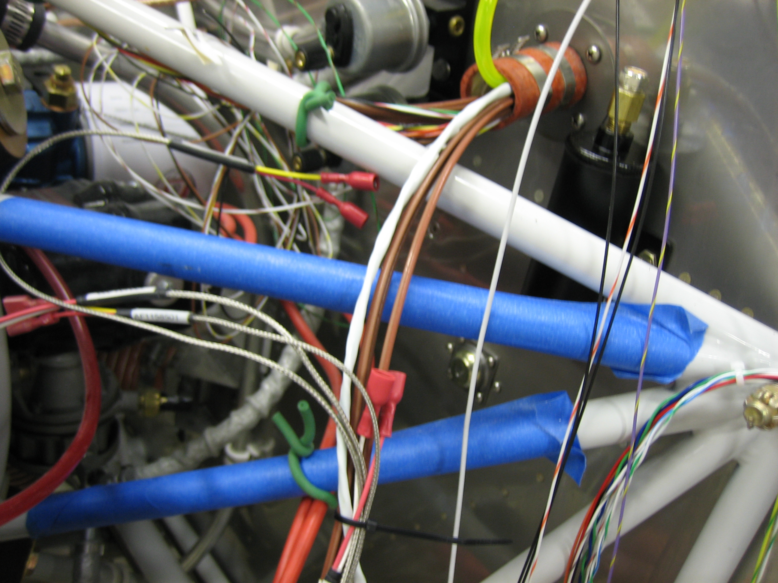
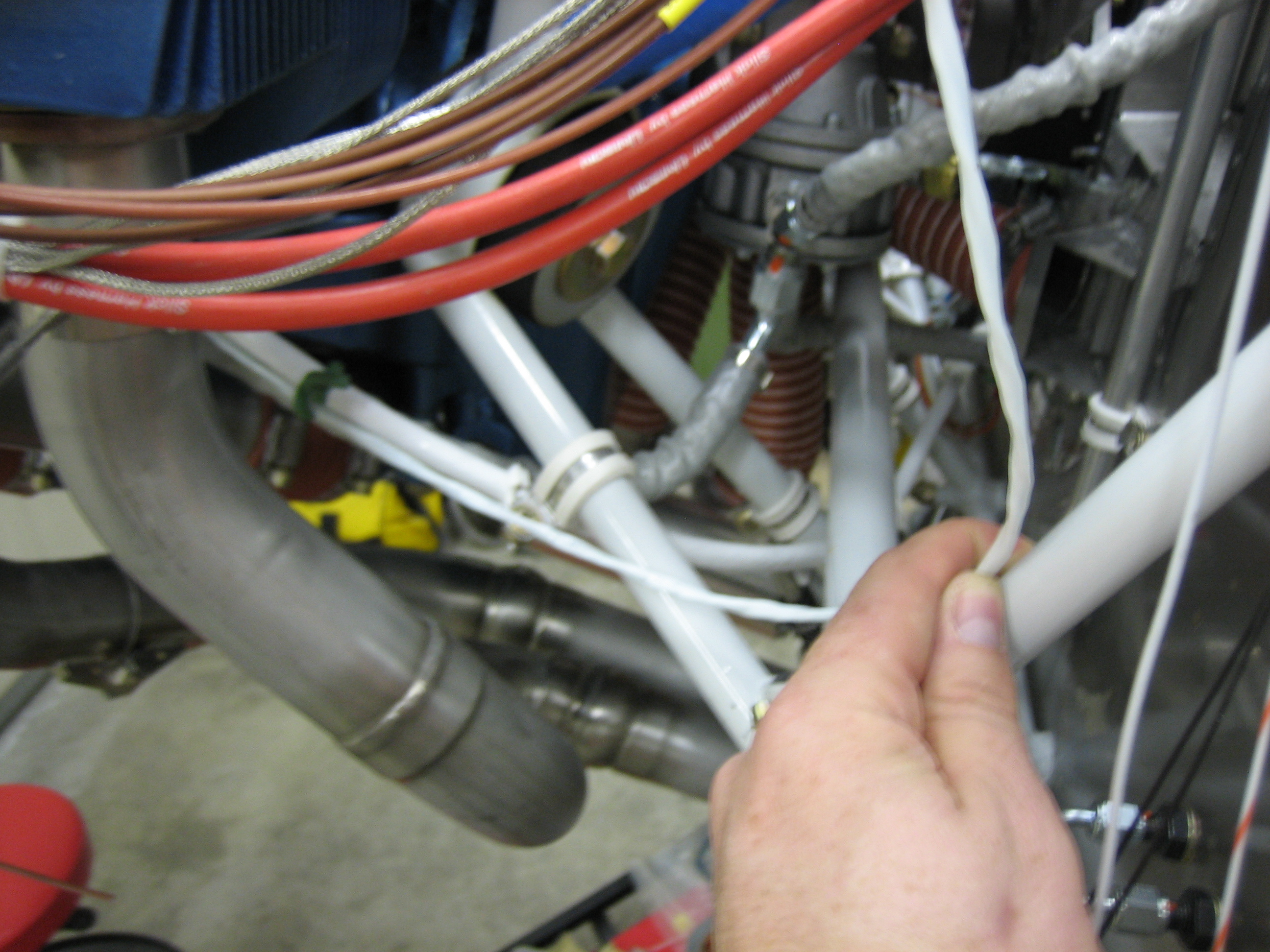
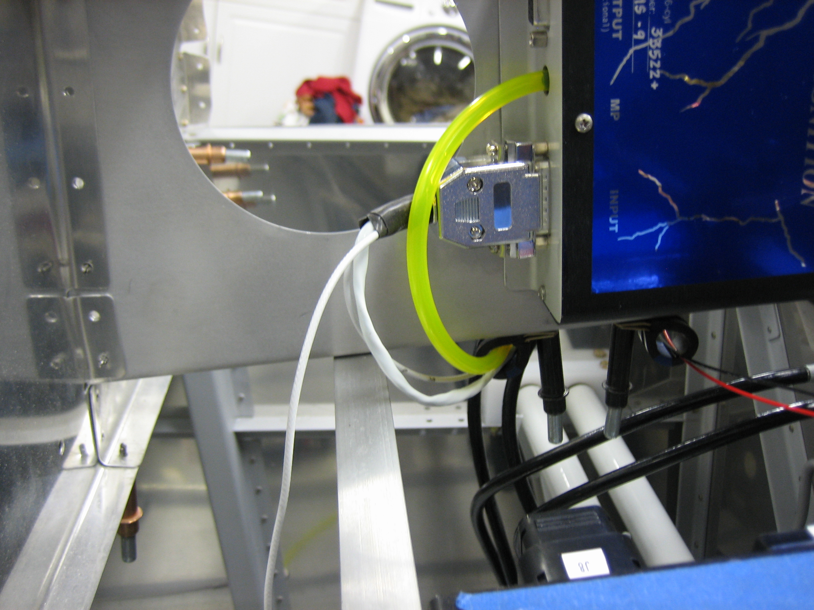
From there, it follows the manifold pressure back and through the aft adel clamp.
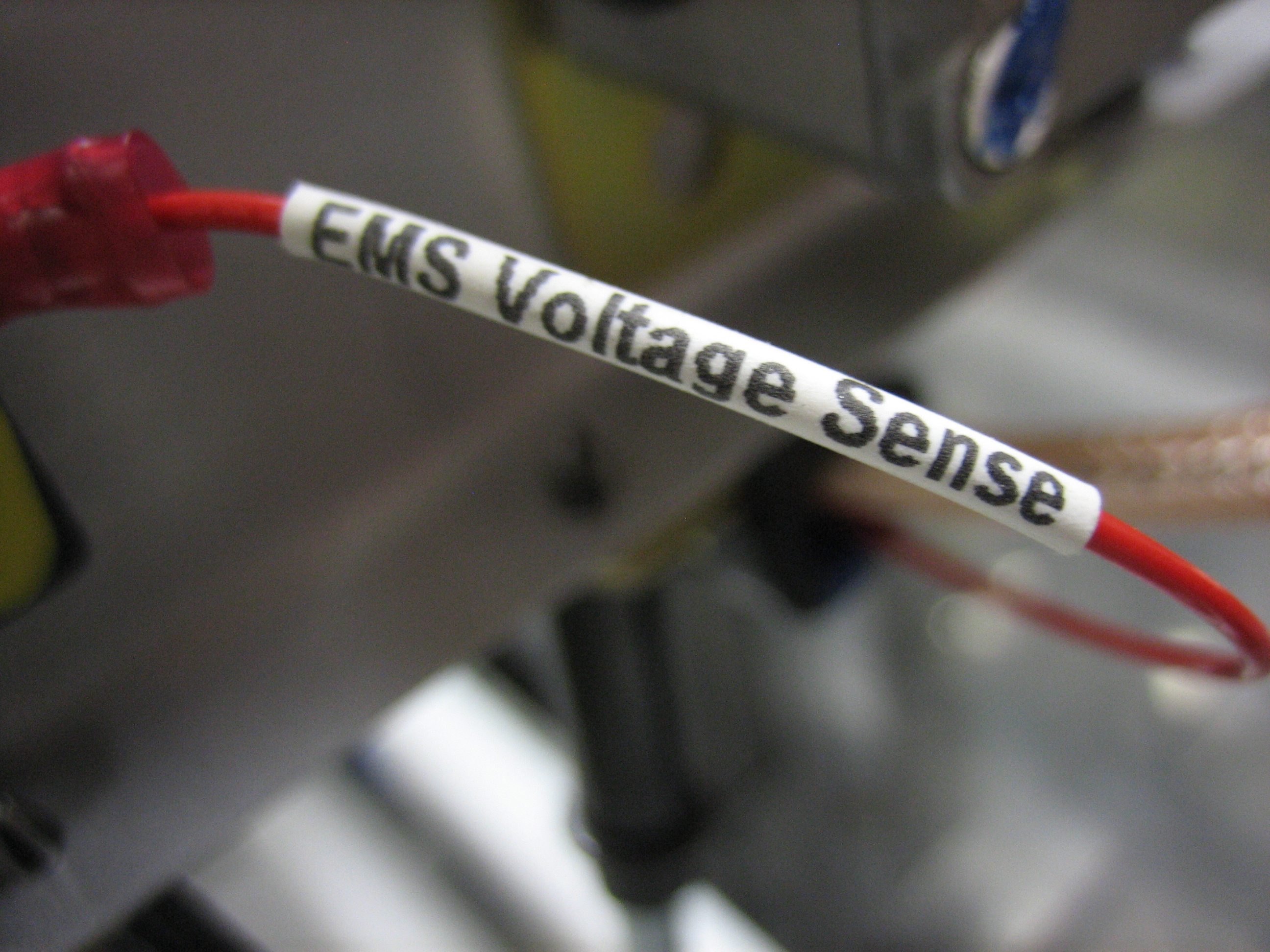
Both then turned upward and connected to the Light Speed ignition box. You can also see a red and black wire running through the right adel clamp. These are the wires from pins 1 and 3 of the EMS. The red wire connects to the battery bus and the black wire connects to the firewall ground block. Together, they’re used to measure battery voltage as well as provide a small amount of power to a couple of the engine sensors.
Both wires run along side the ignition wires. The black wire then separates here and connects to the ground block. You can also see that I connected the two VP-X ground wires to their appropriate pins on the J10 and J12 connectors. These are 18AWG (vs the 22AWG from the EMS) since they carry power for the flap and trim motors which can draw several amps.
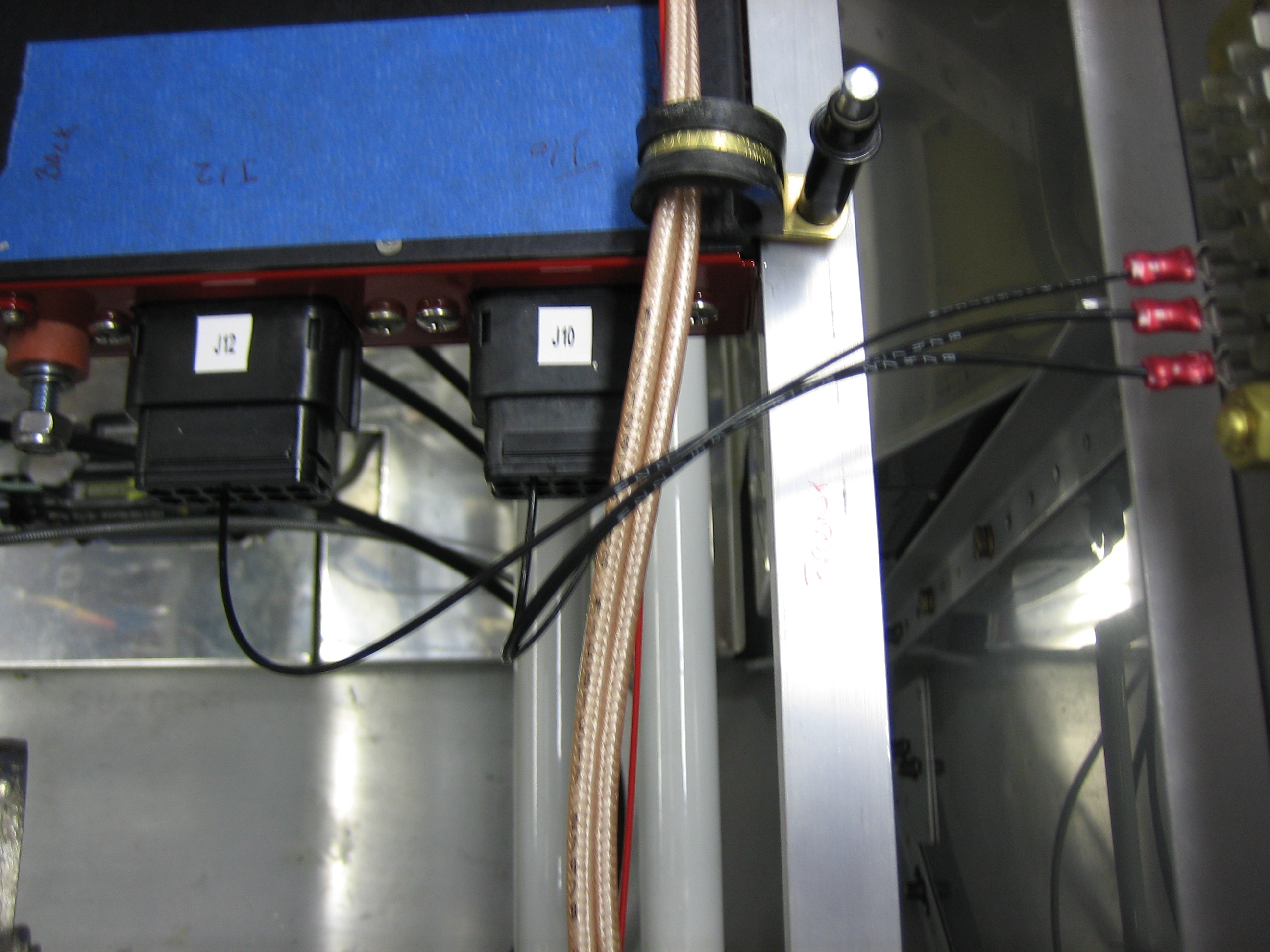
The red wire continues on through the front adel clamp and connects to the battery bus.
The label maker I’m using can print on heat shrink tubing. I’m using that to label certain wires. All ground wires in the plane will be black, so there’s no need to label them. All power wires will be labeled as well as both ends of signal wires.