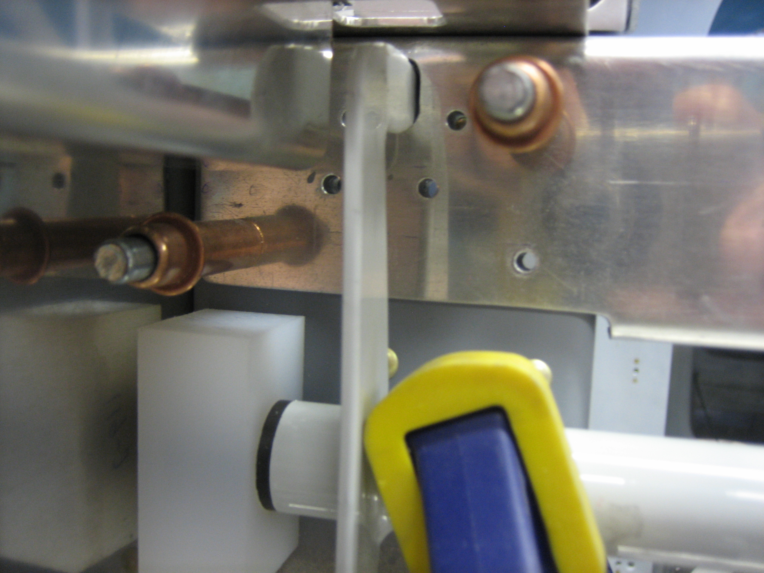
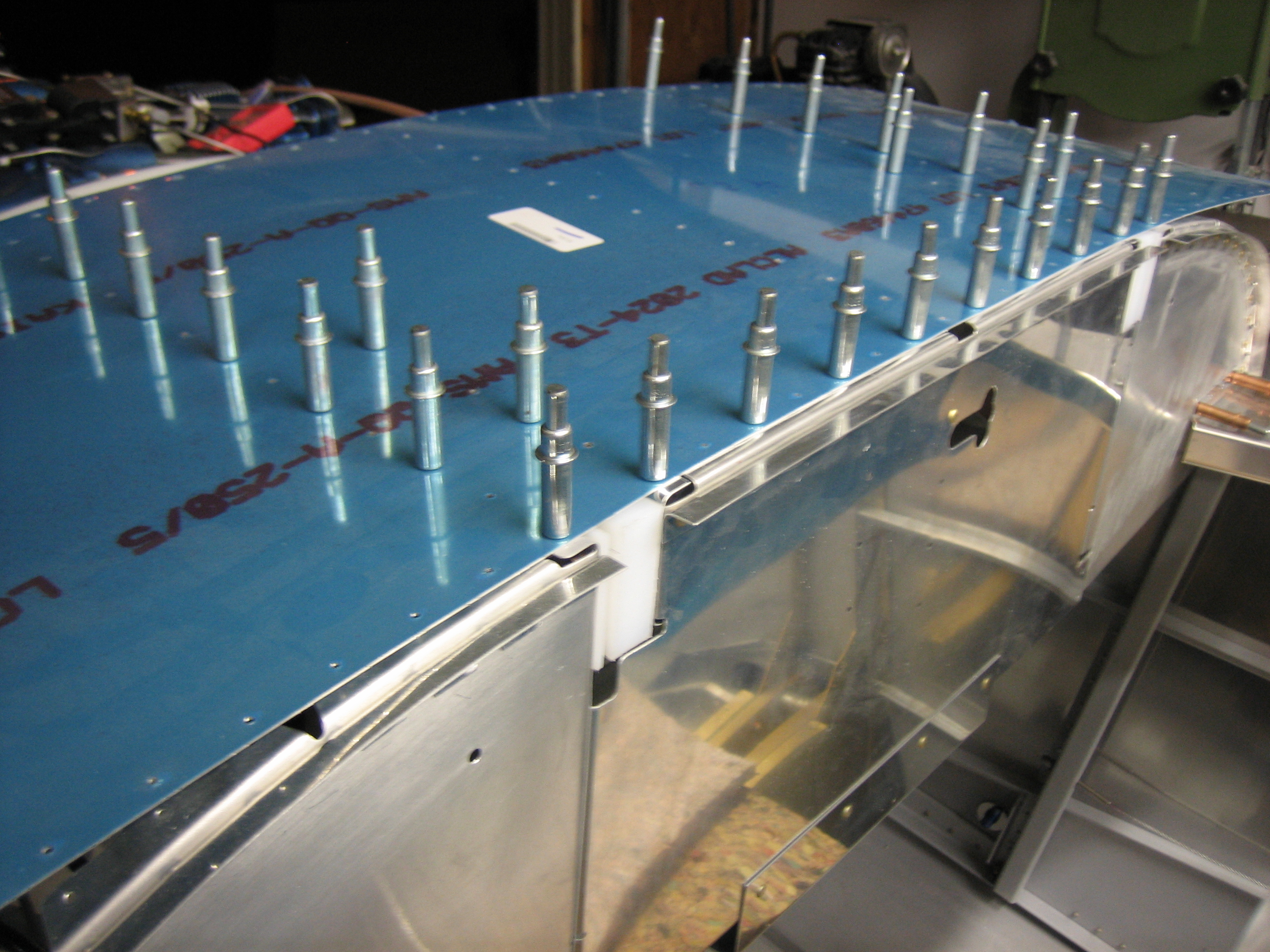
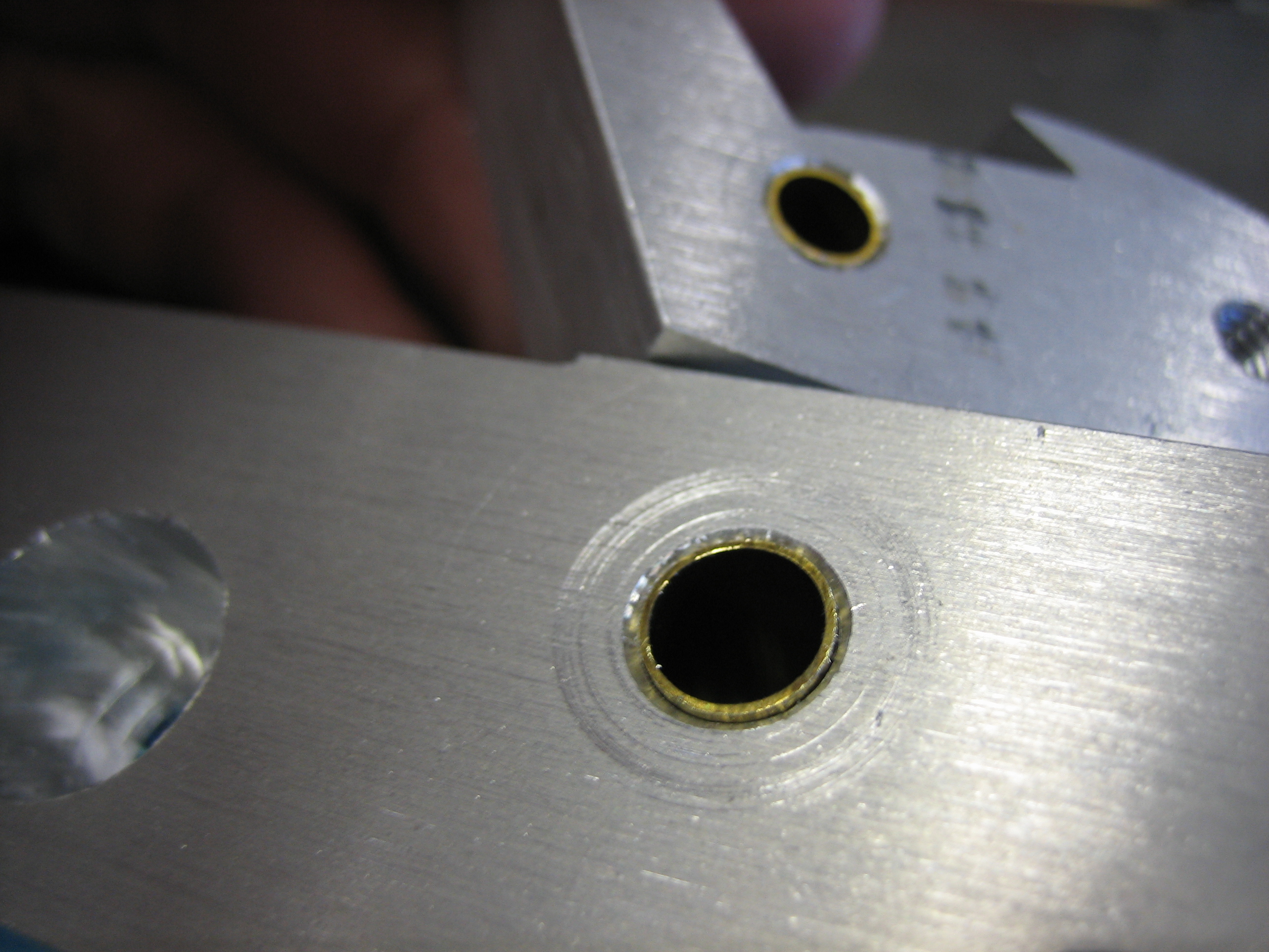
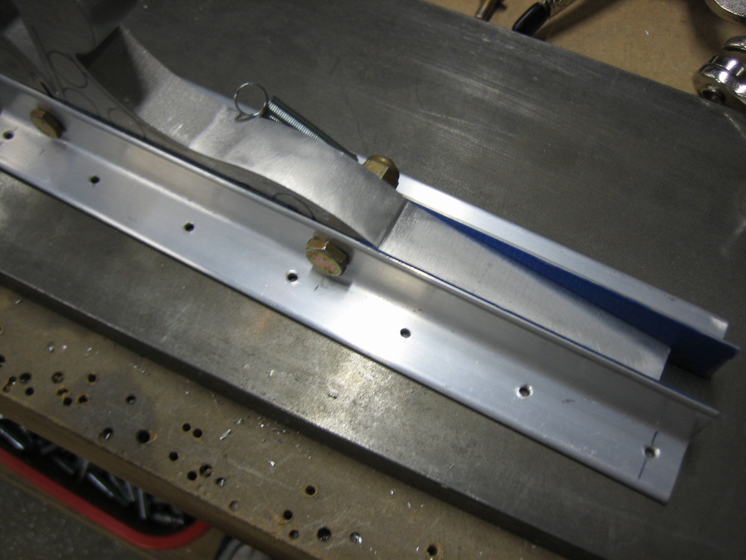
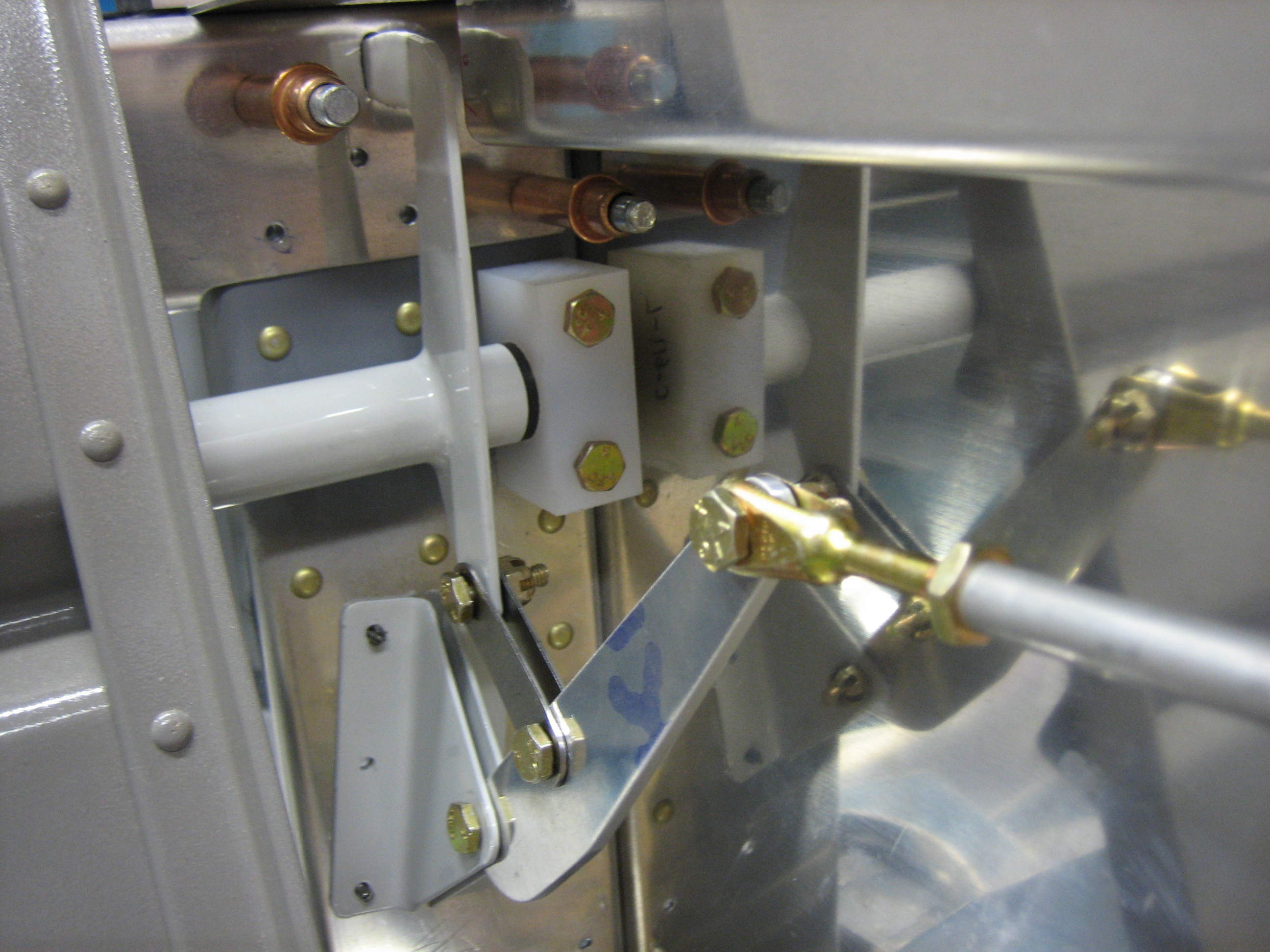
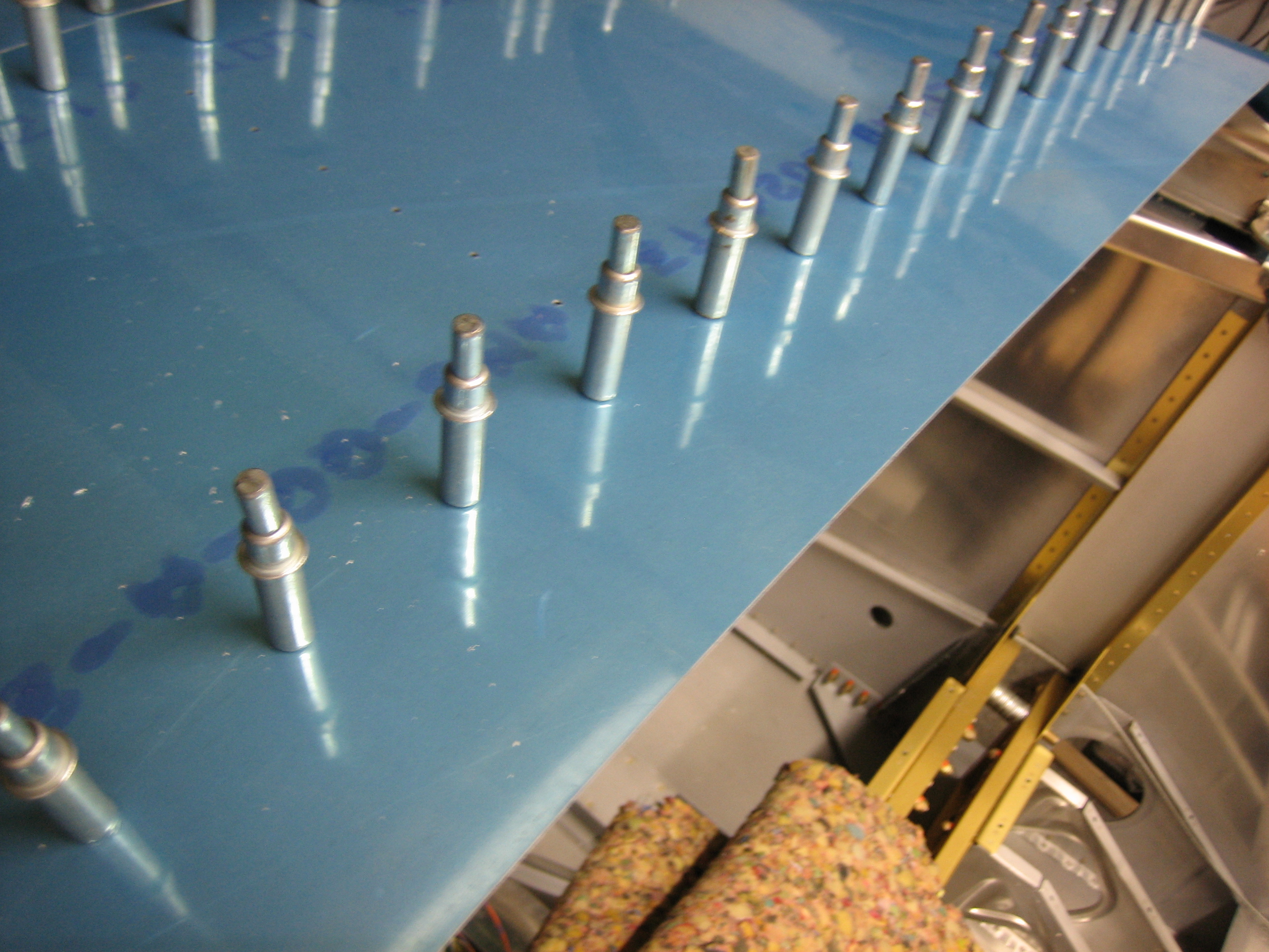
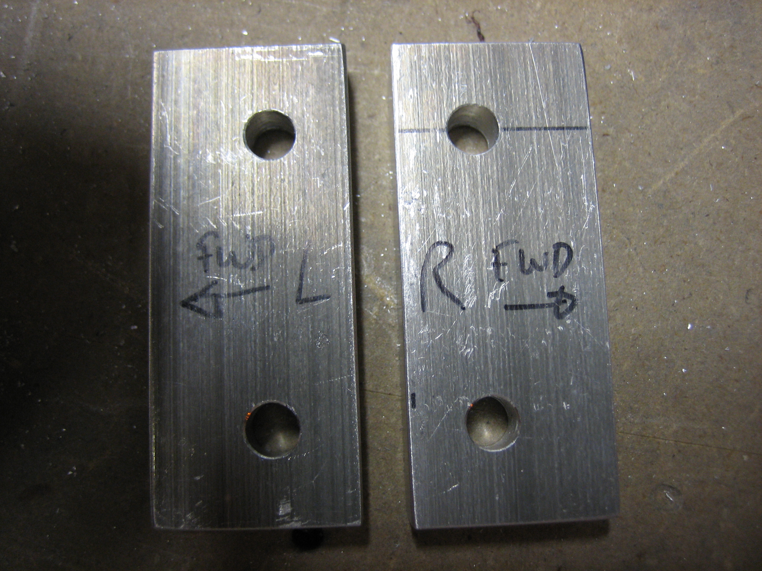
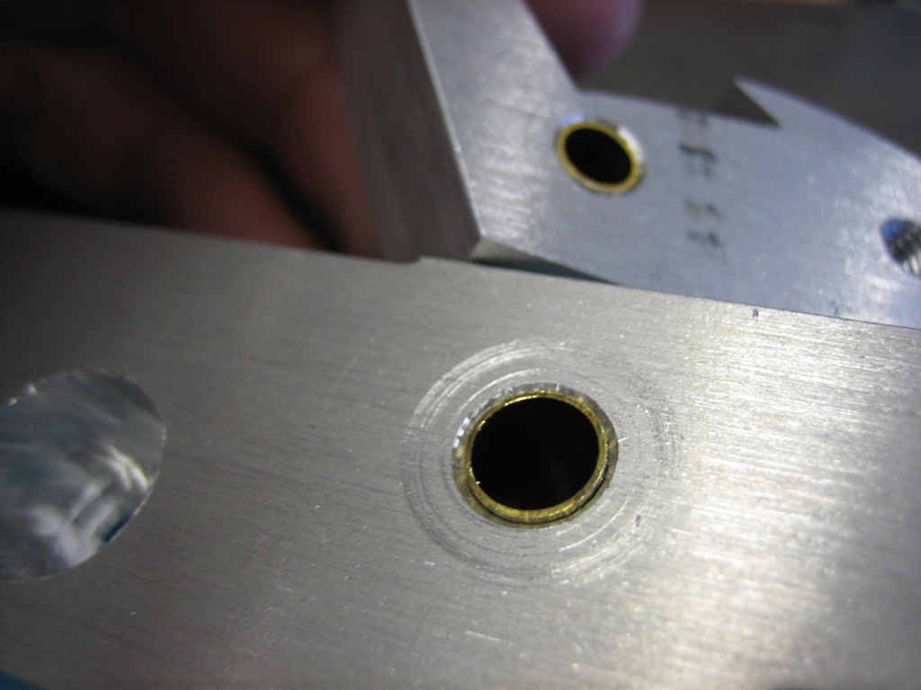
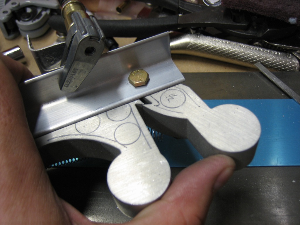
I stopped by the hardware store this morning and picked up some 7/32″ and 9/32″ brass tubing. I then drill out the latch pieces so that these are a press fit into the holes. This will allow the brass tubing to rotate around the bolt. This totally fixed the sloppy fit and the bolts are a slip fit through the holes now. I’m not going to install these permanently in the holes yet since I’m planning on having the latch components hard anodized.
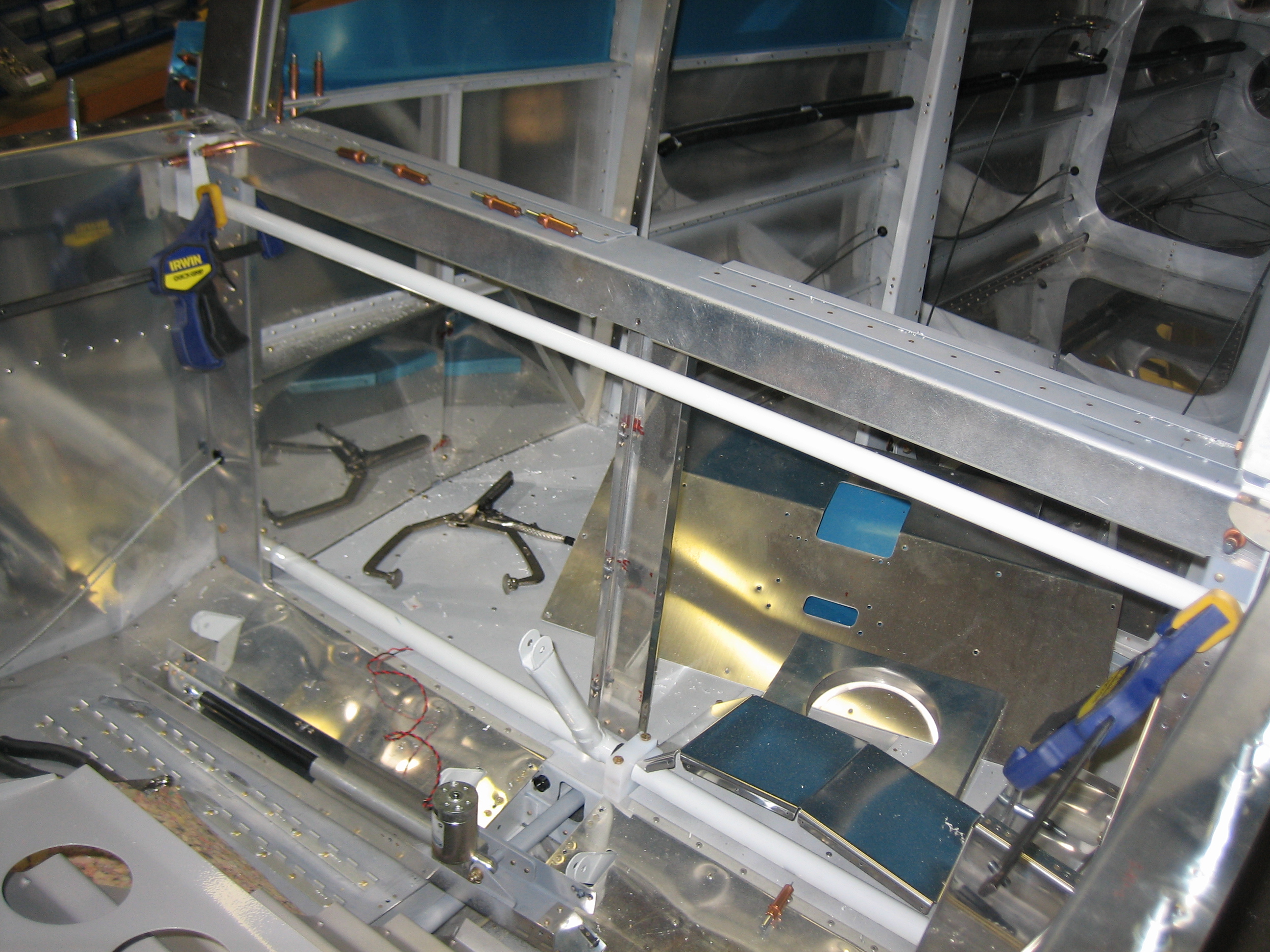
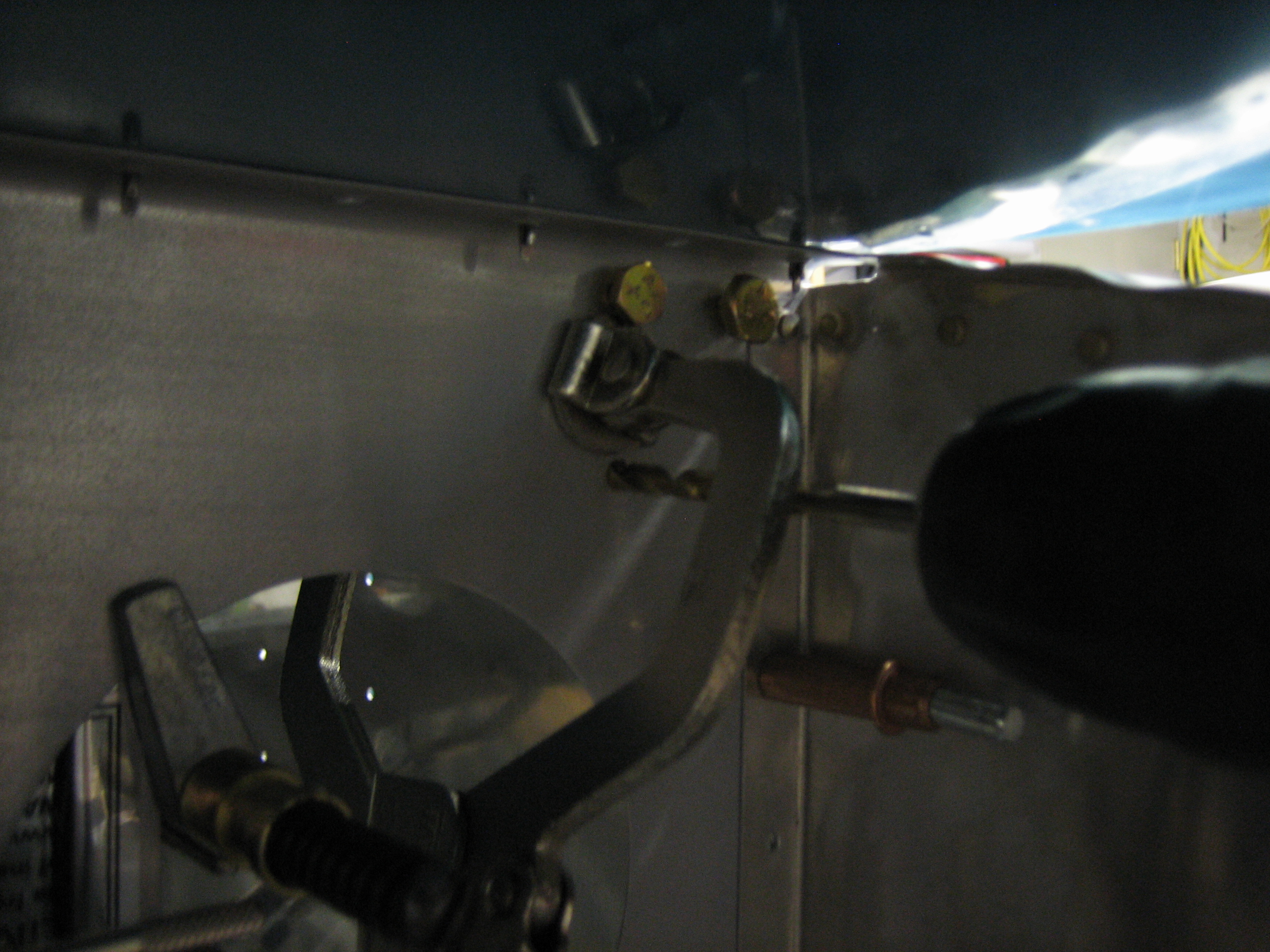
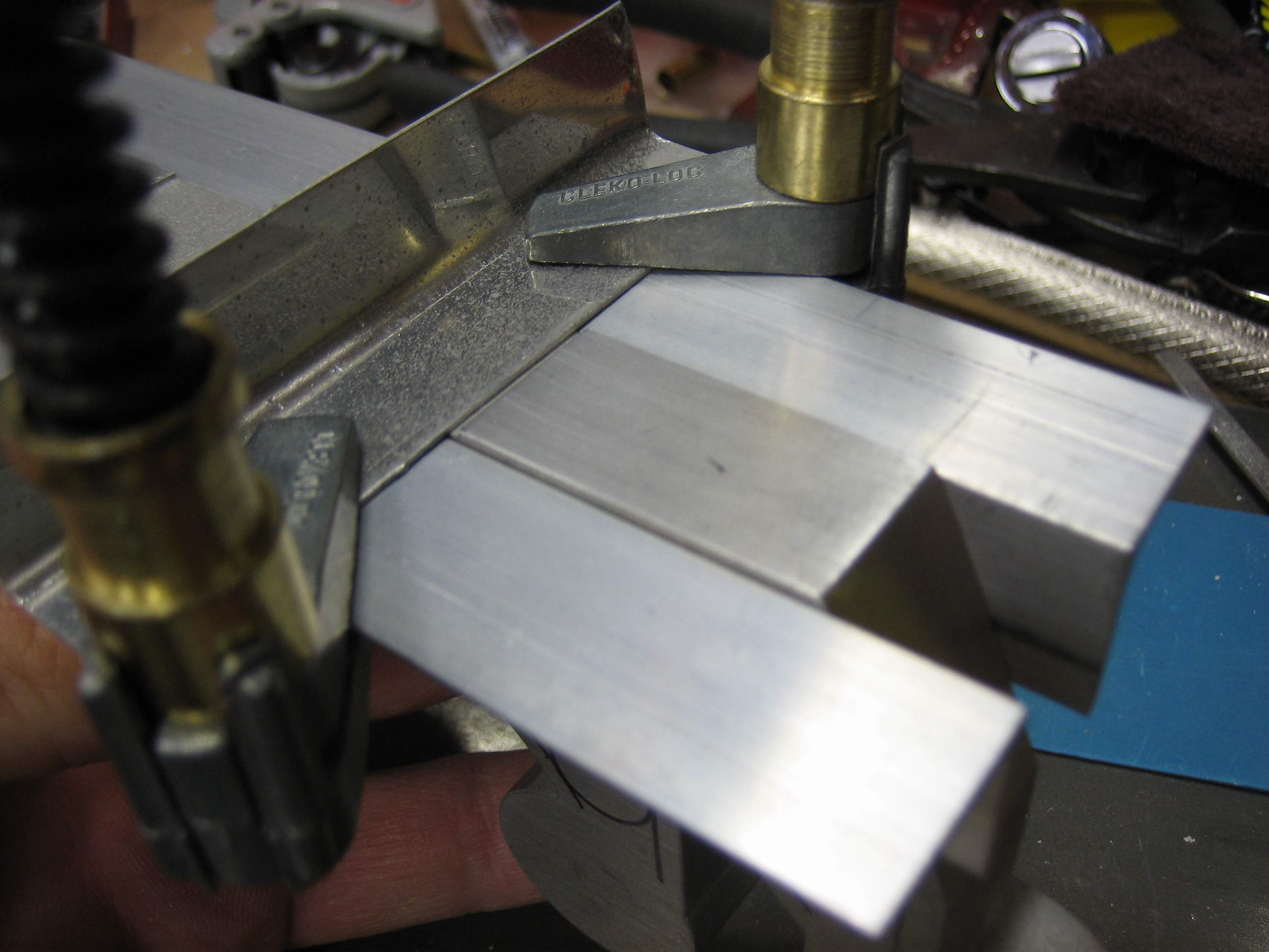
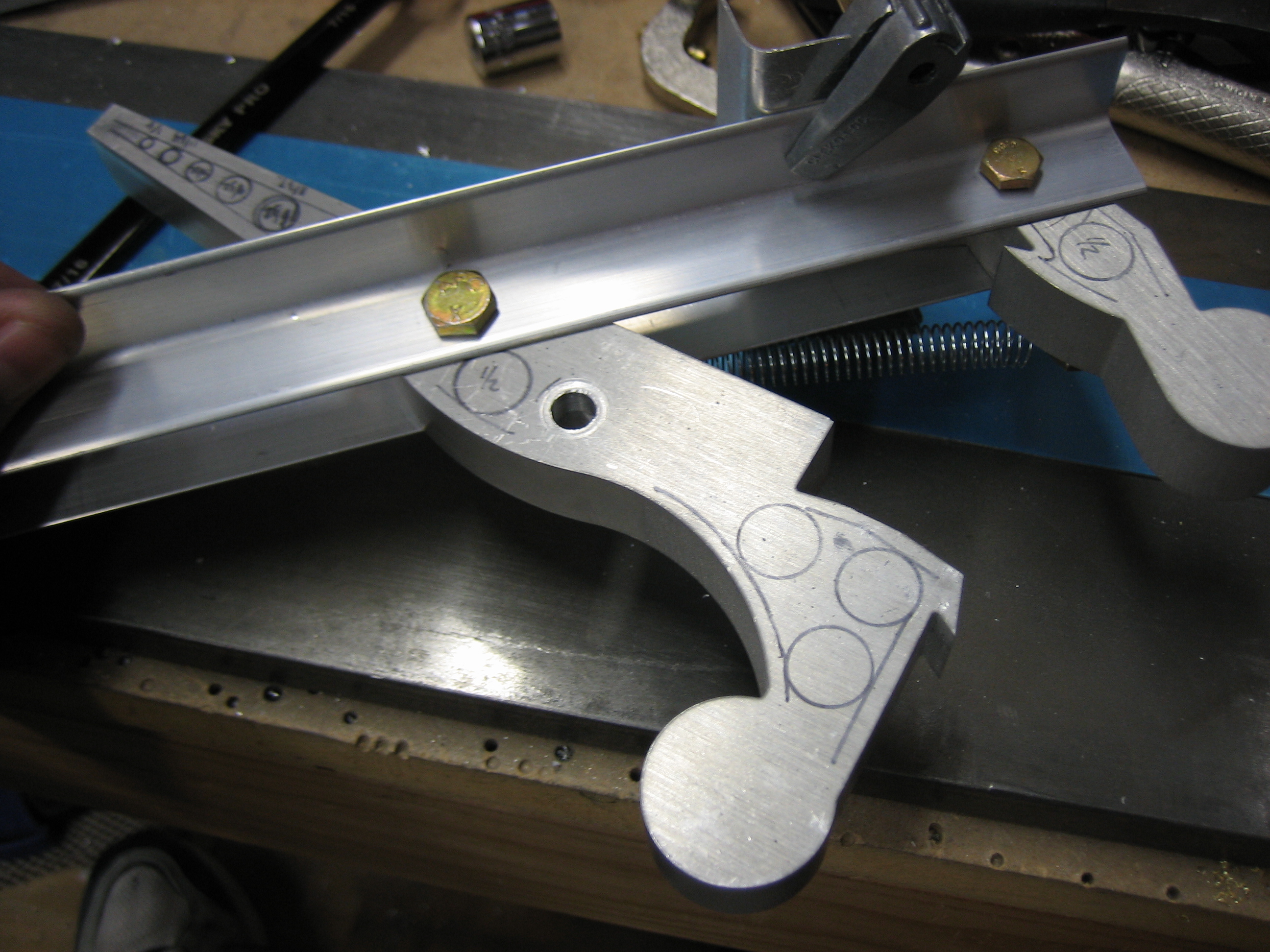
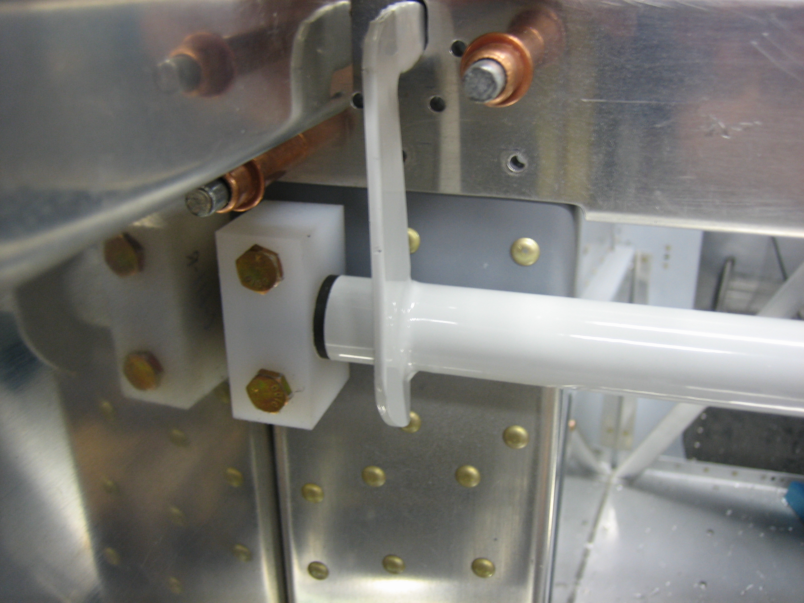
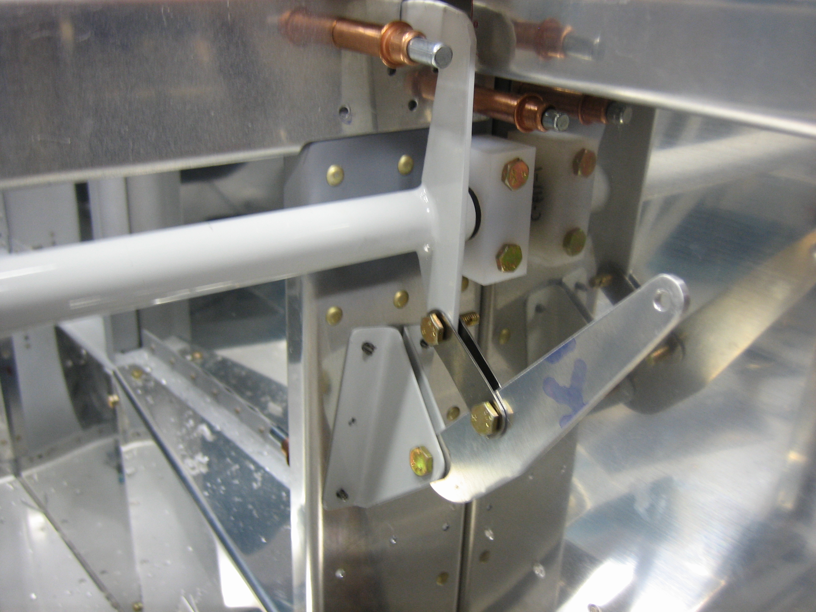
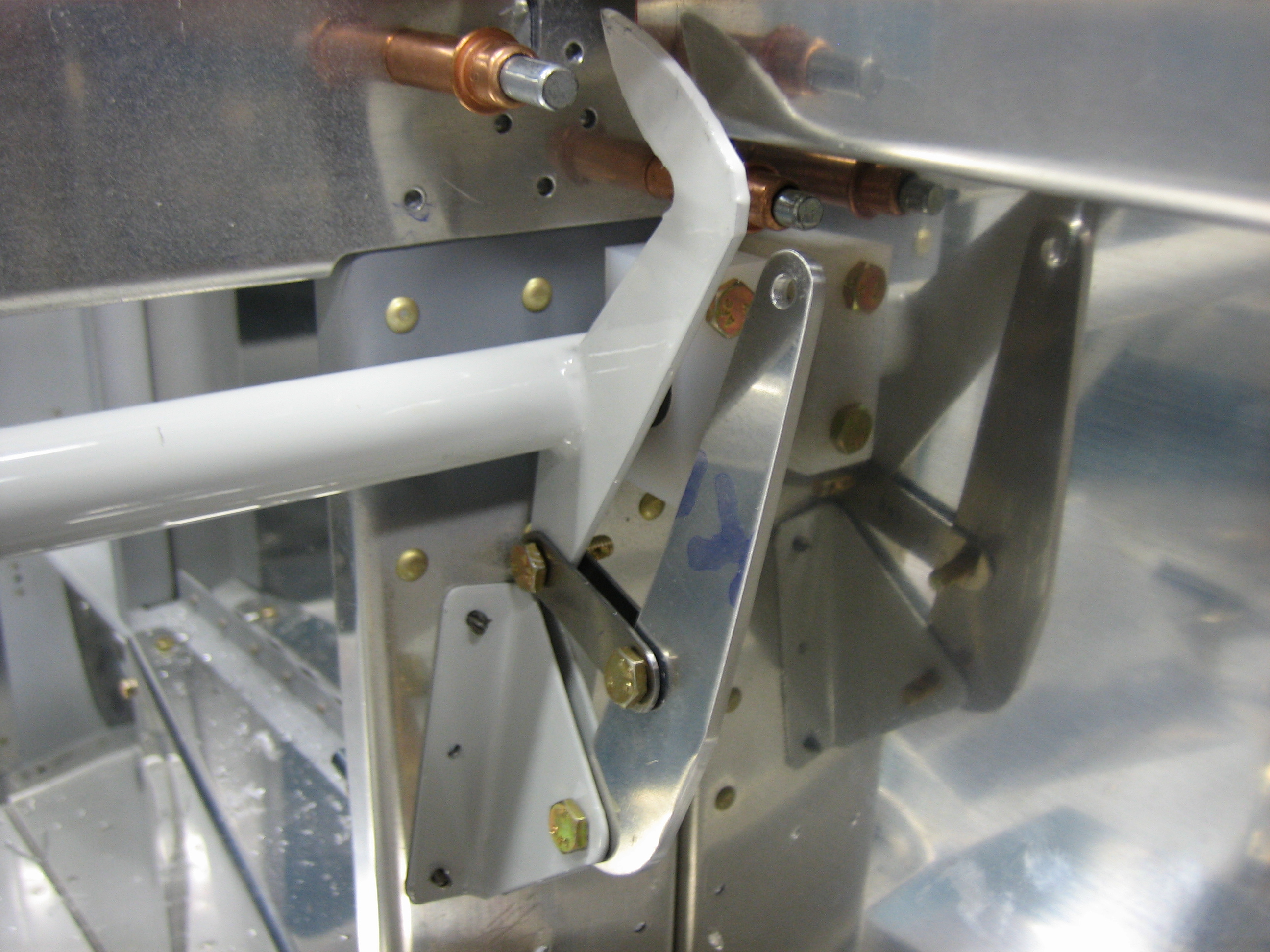
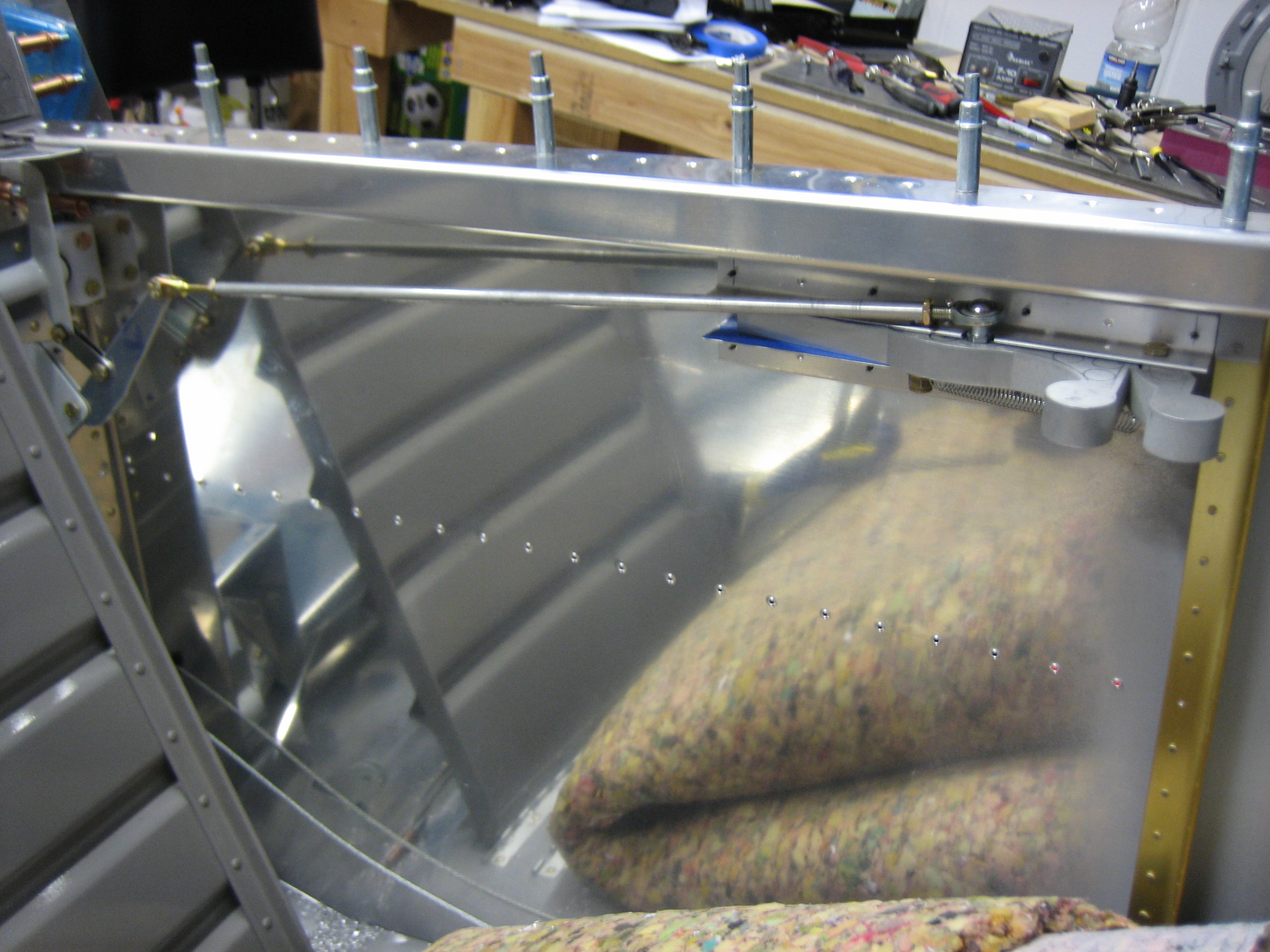
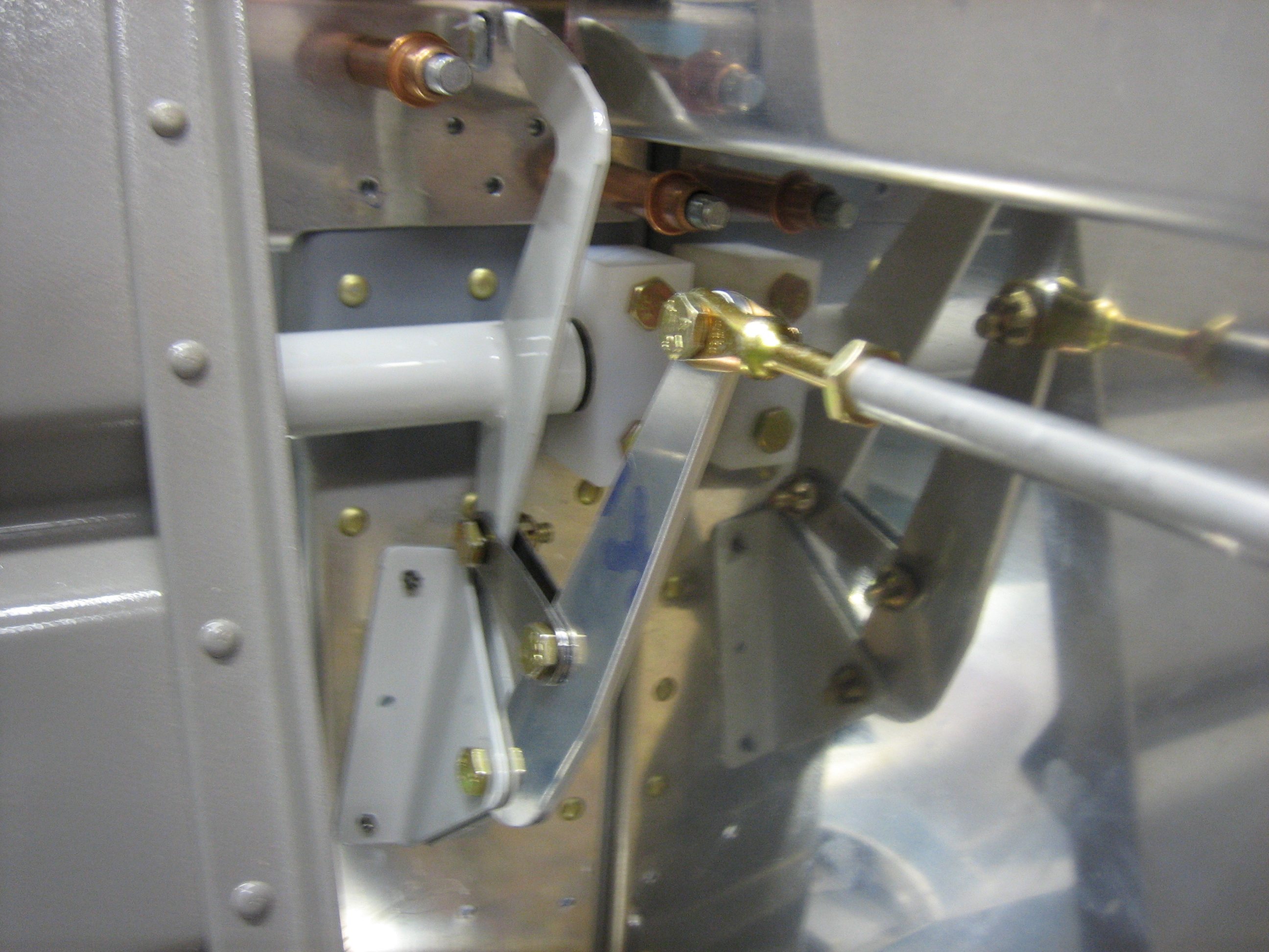
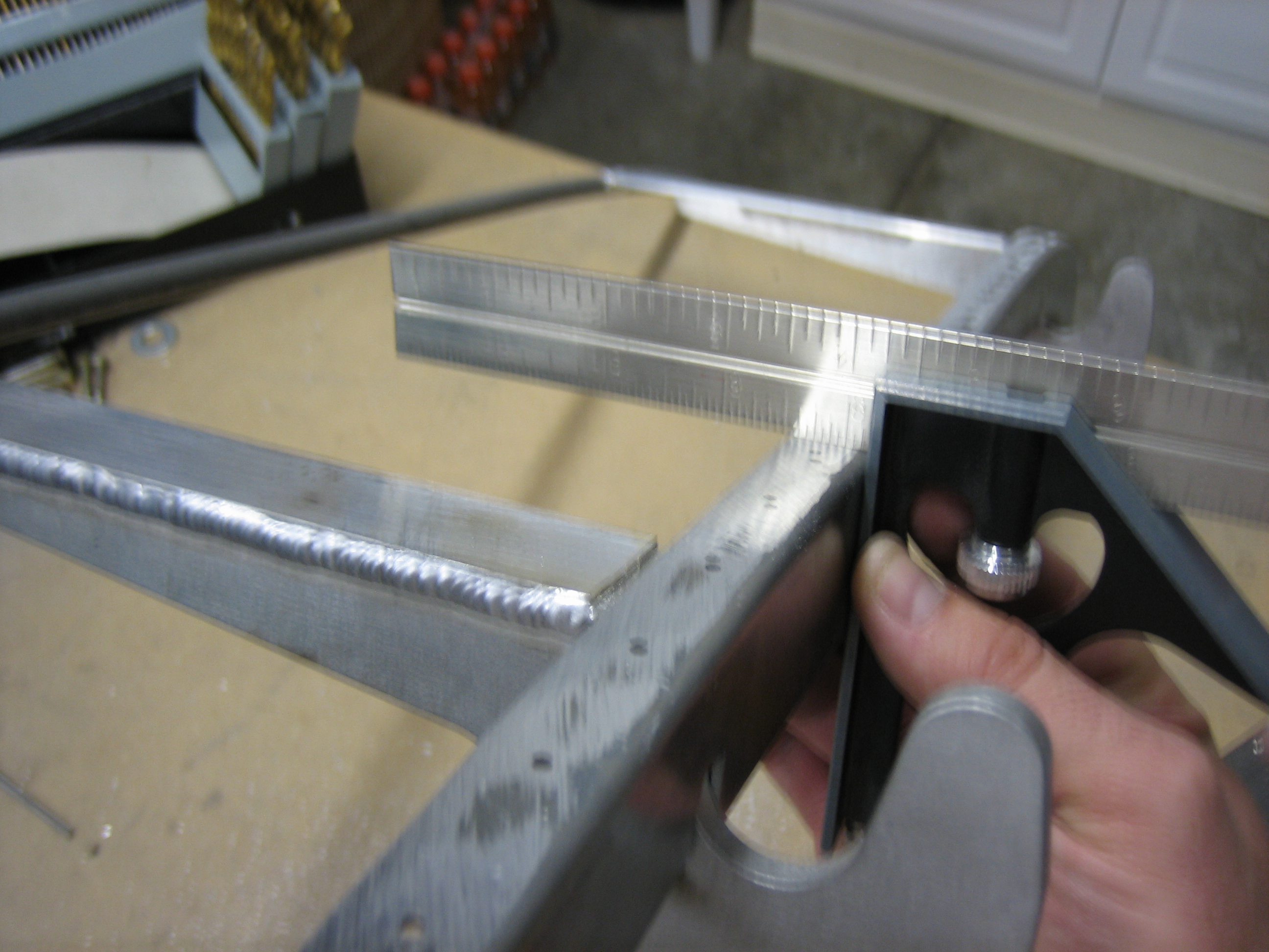
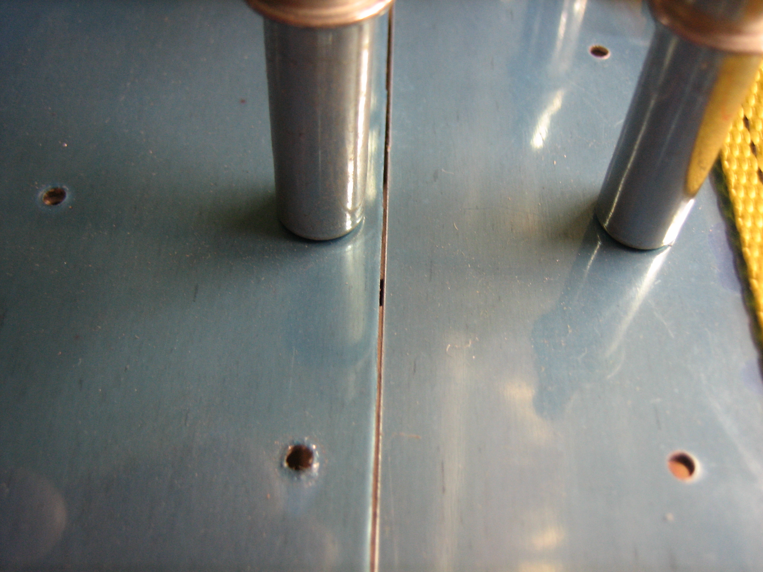
I also drilled the latch attach angles to the latch components. Here is the latch temporarily assembled so that I can check the clearances and movement.
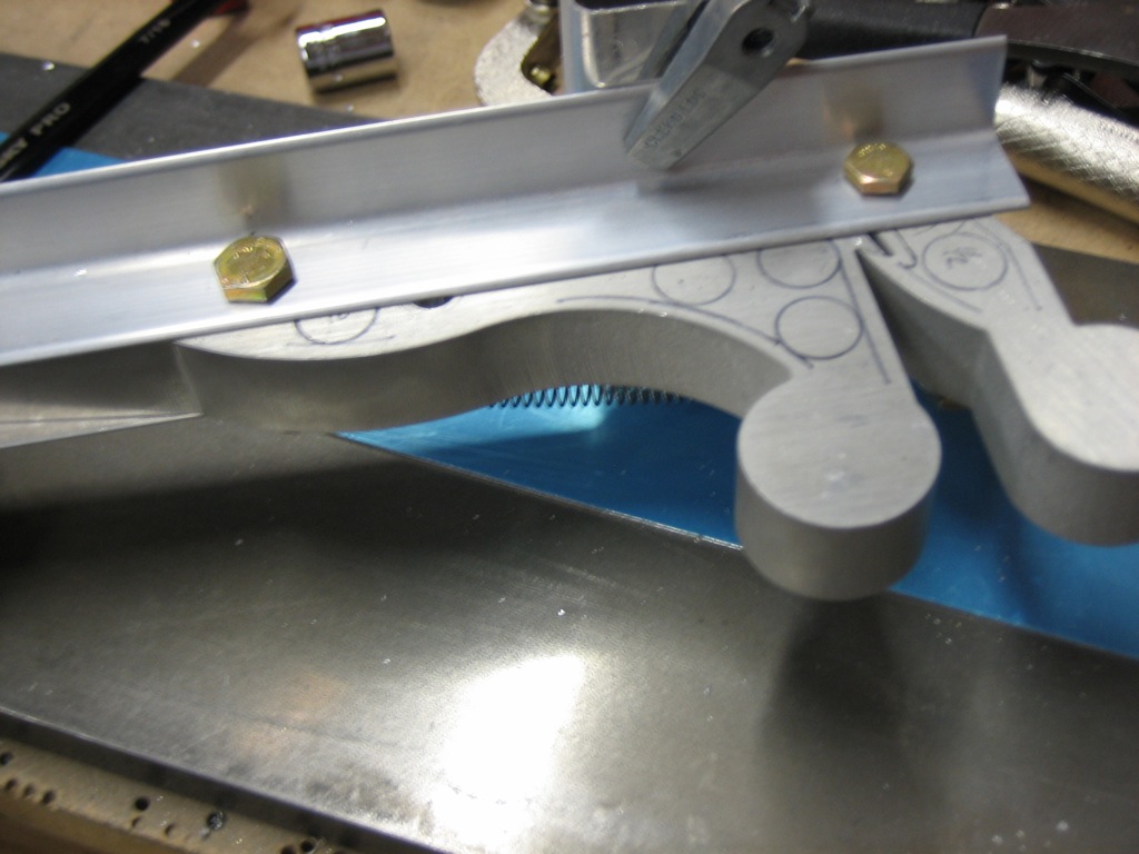
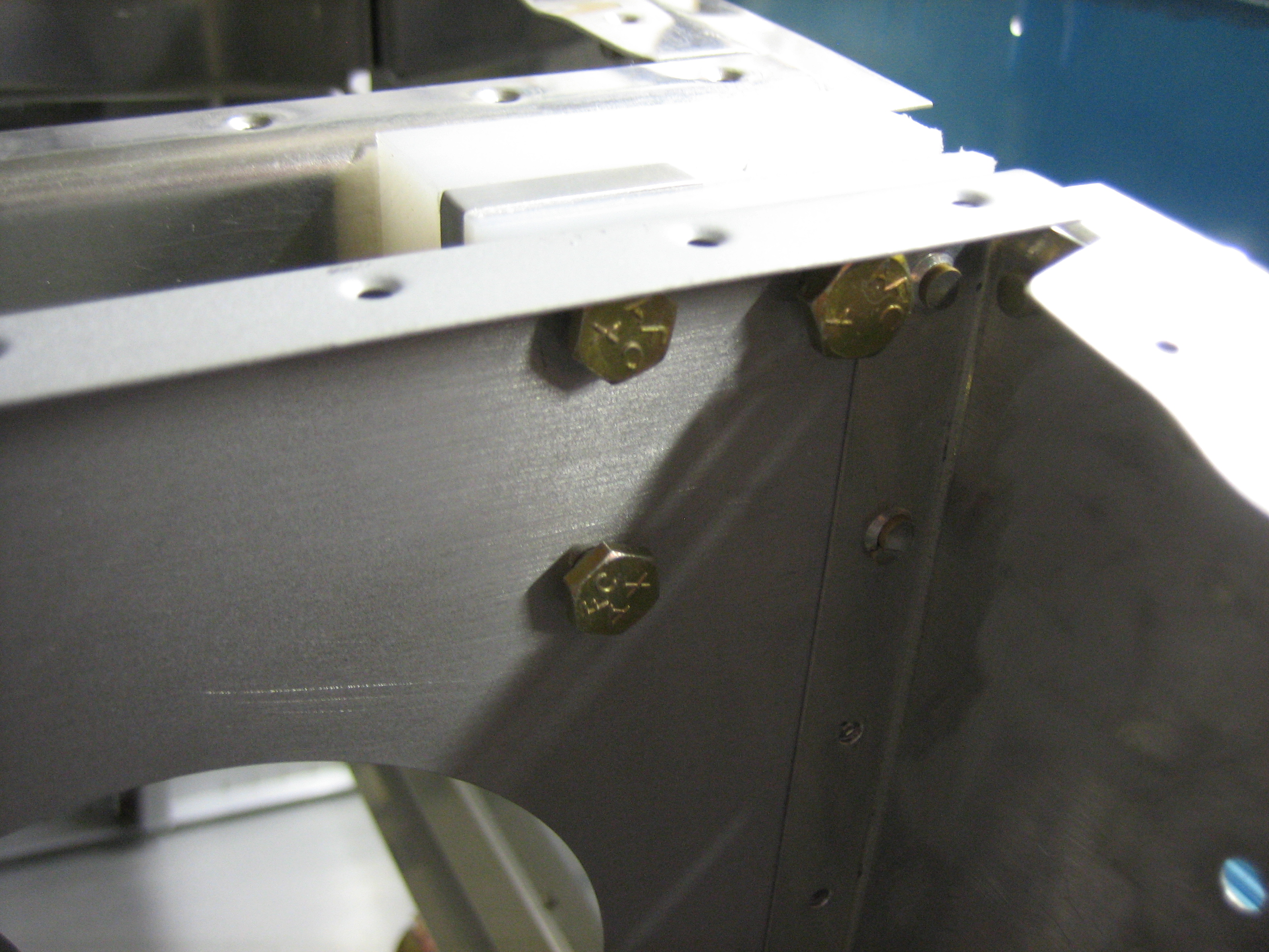
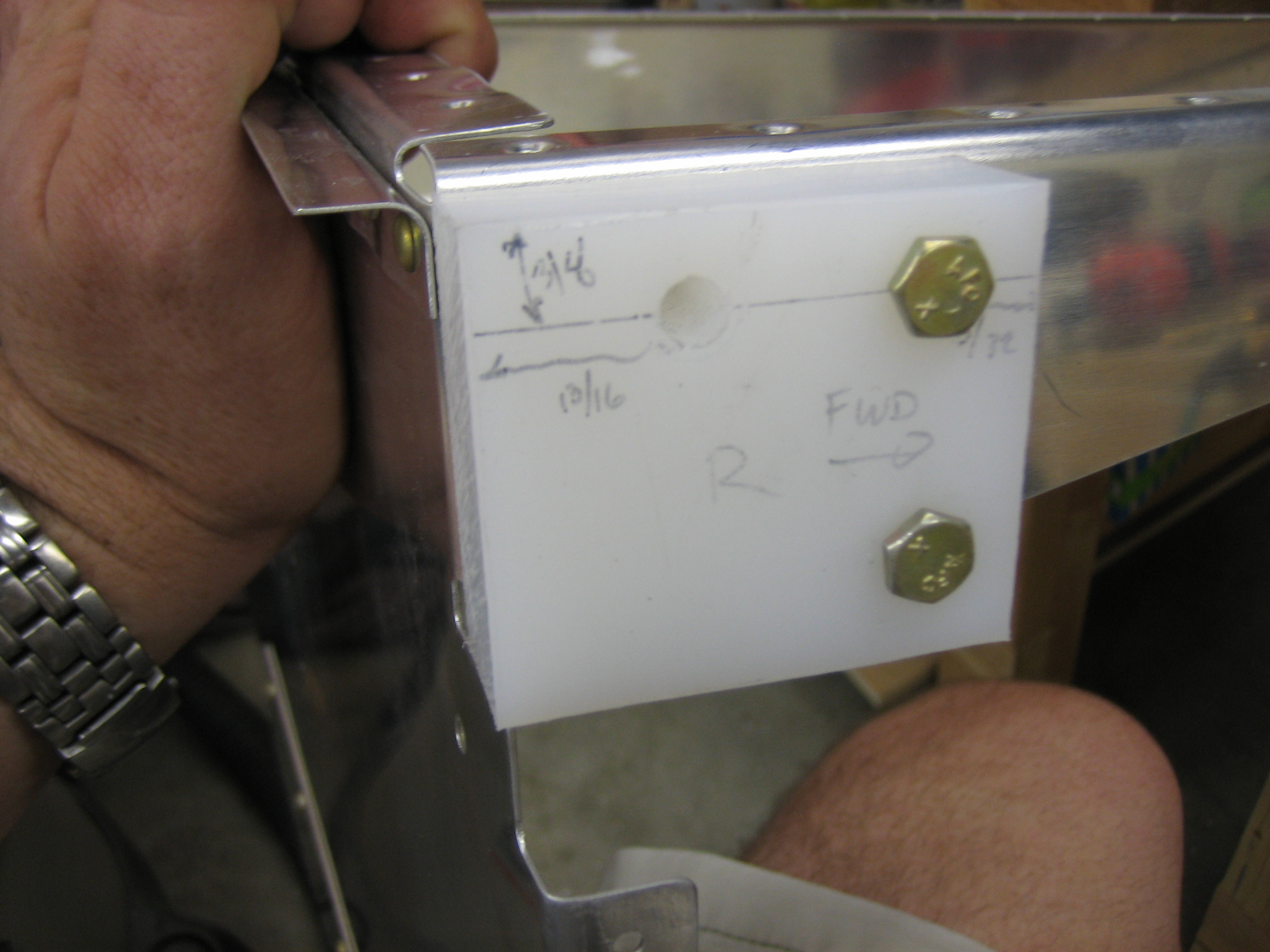
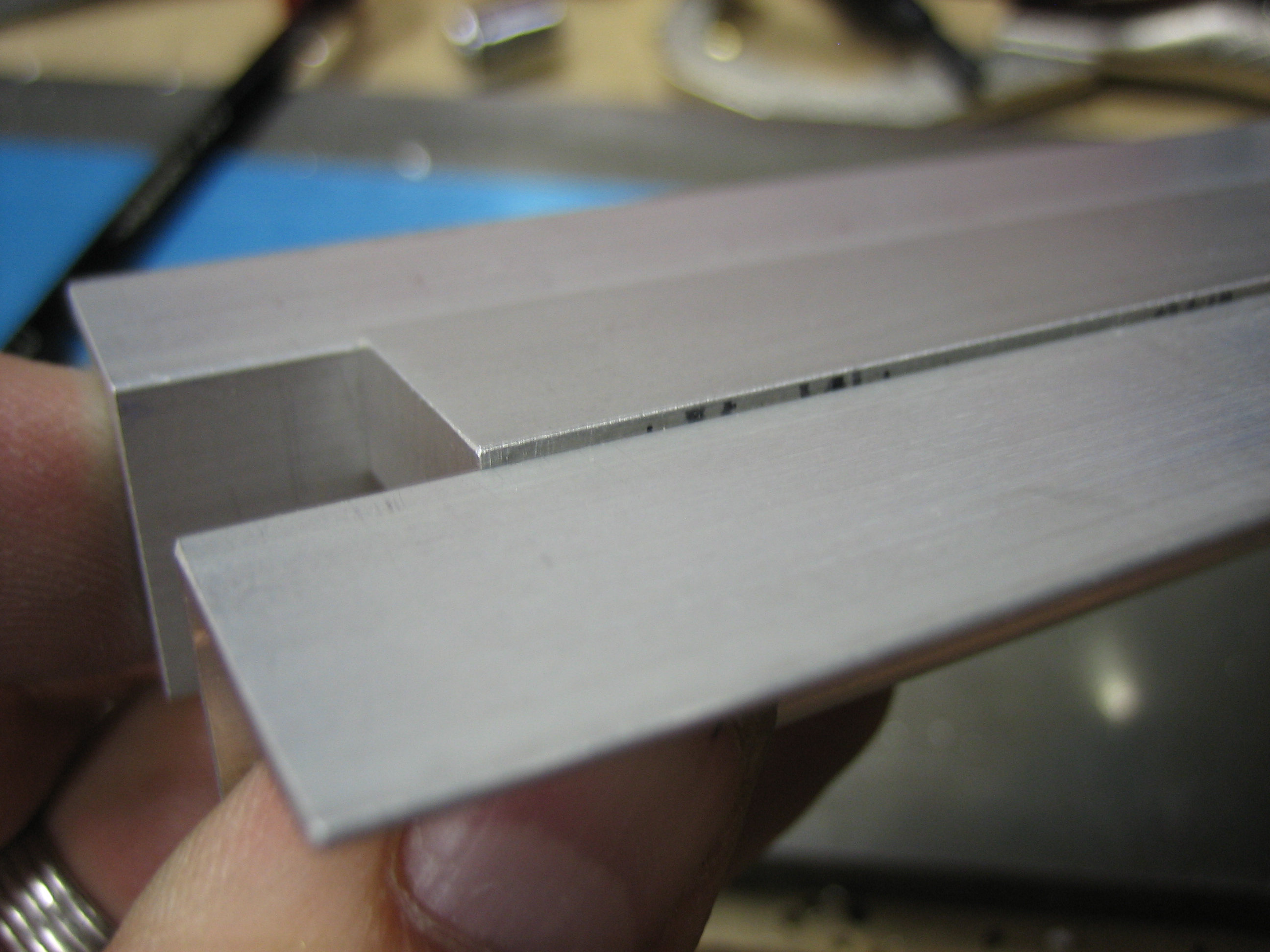
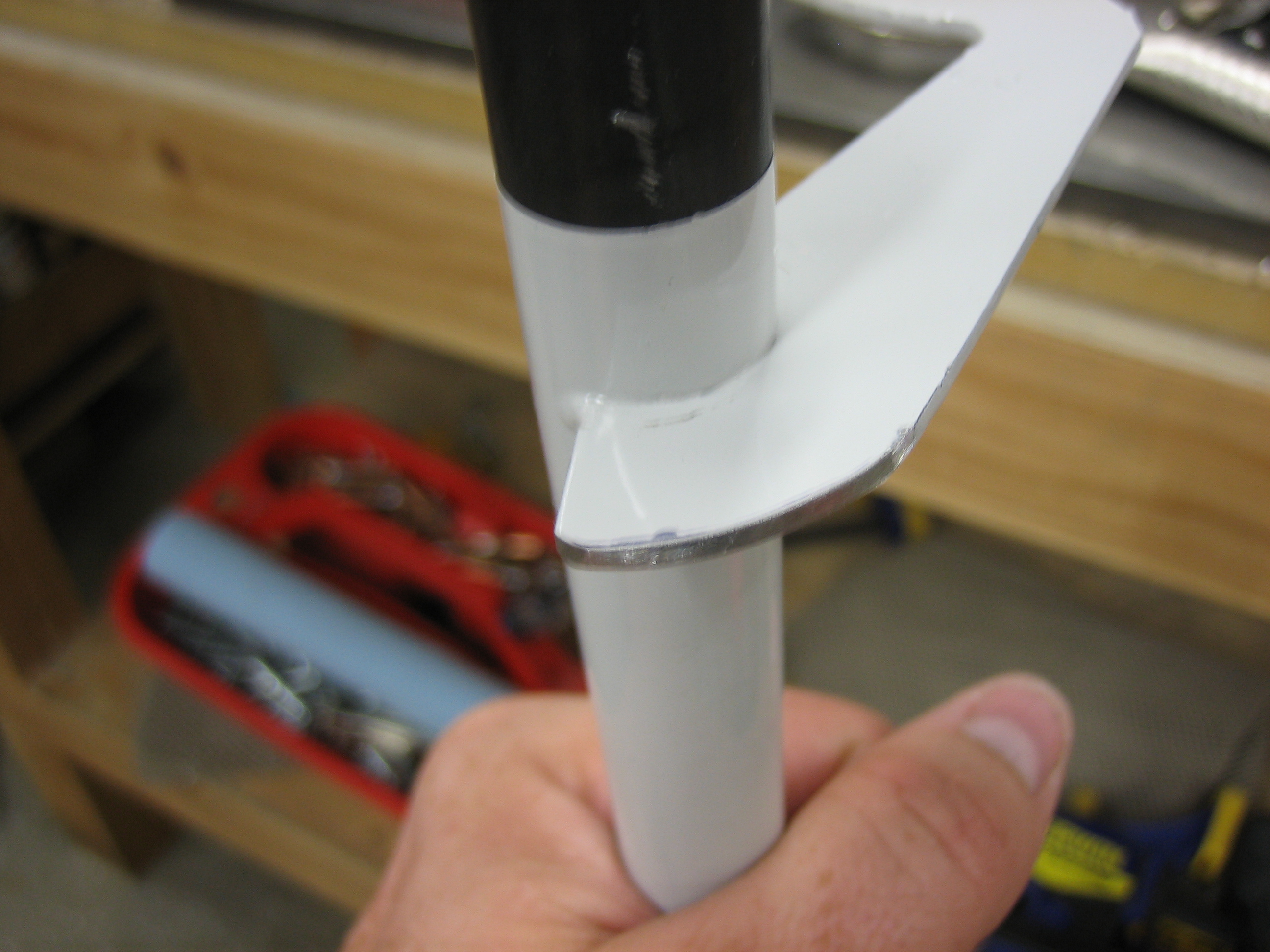
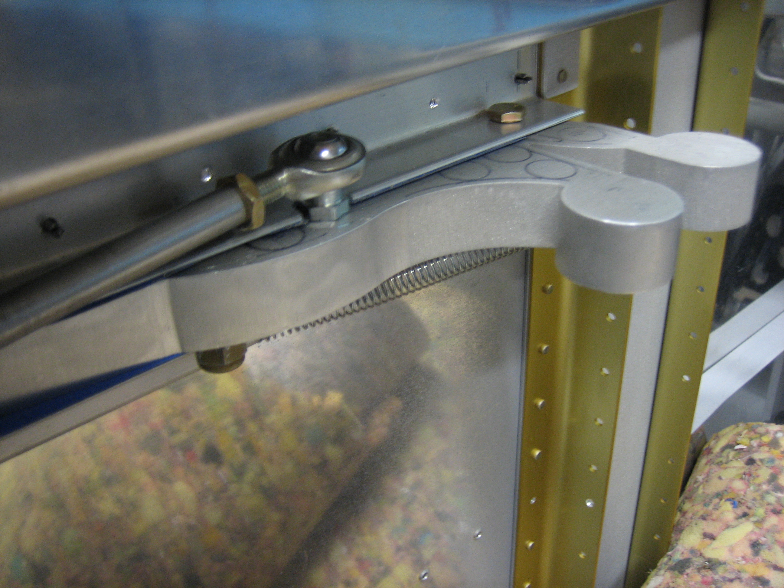
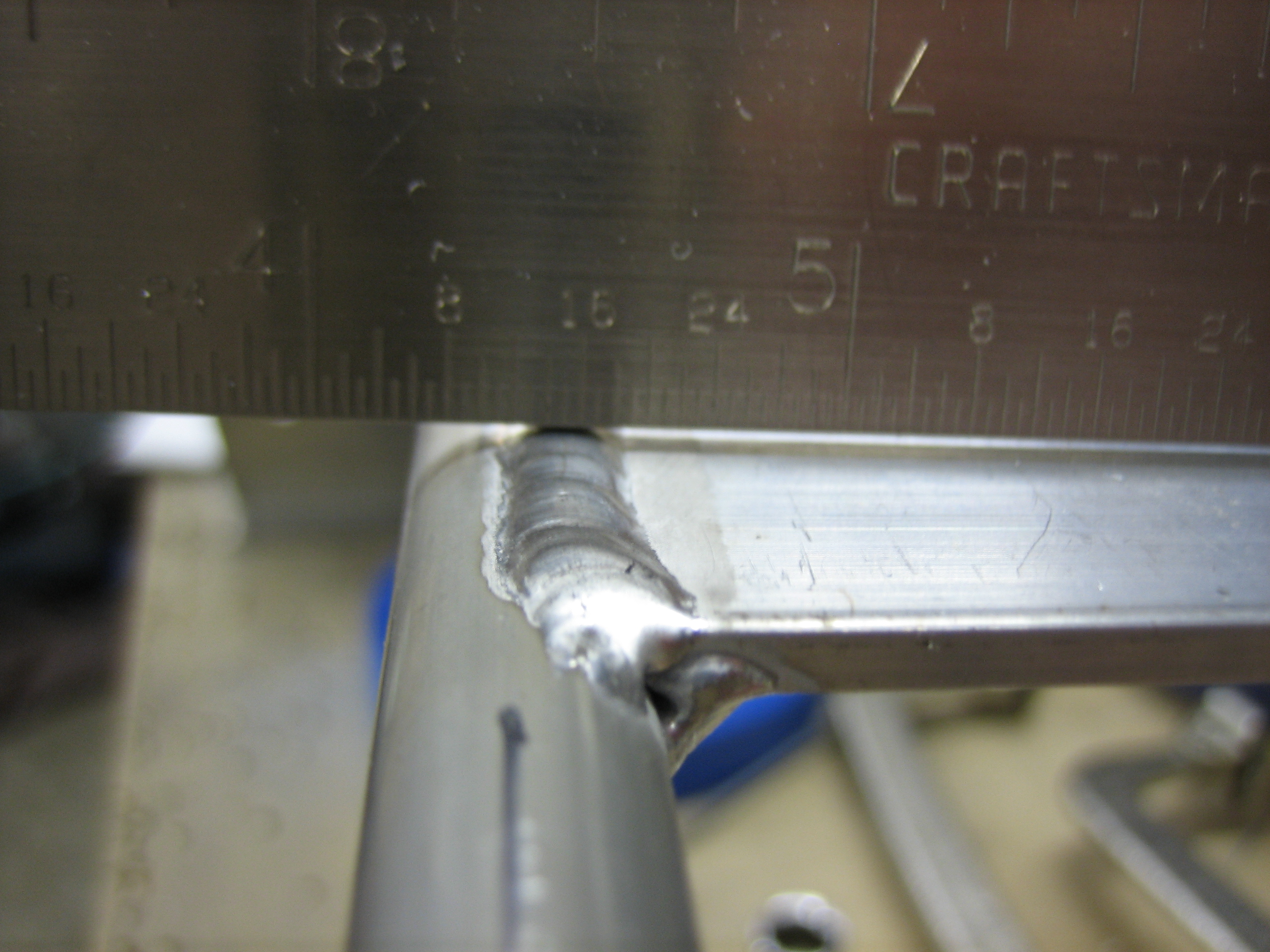
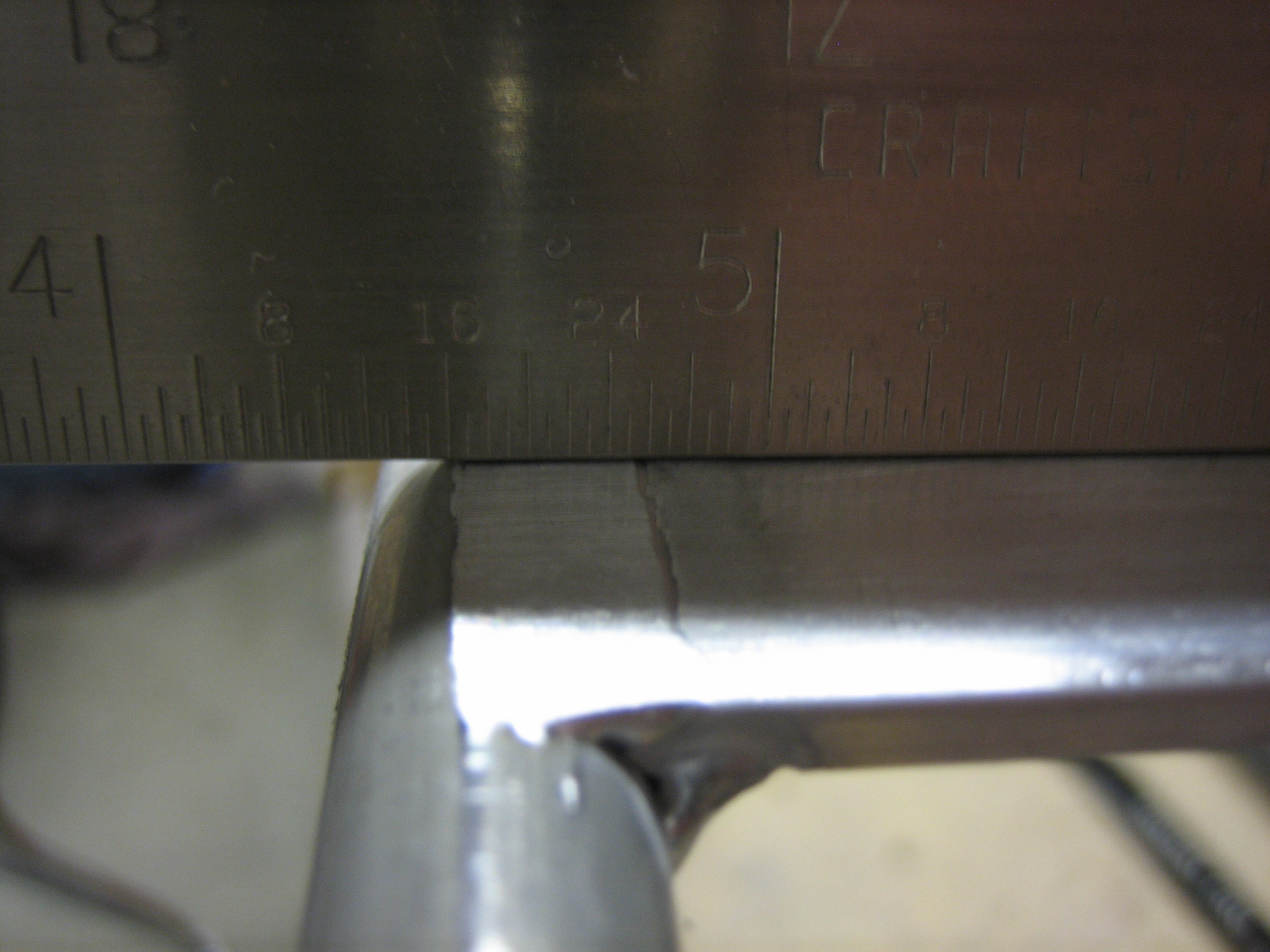
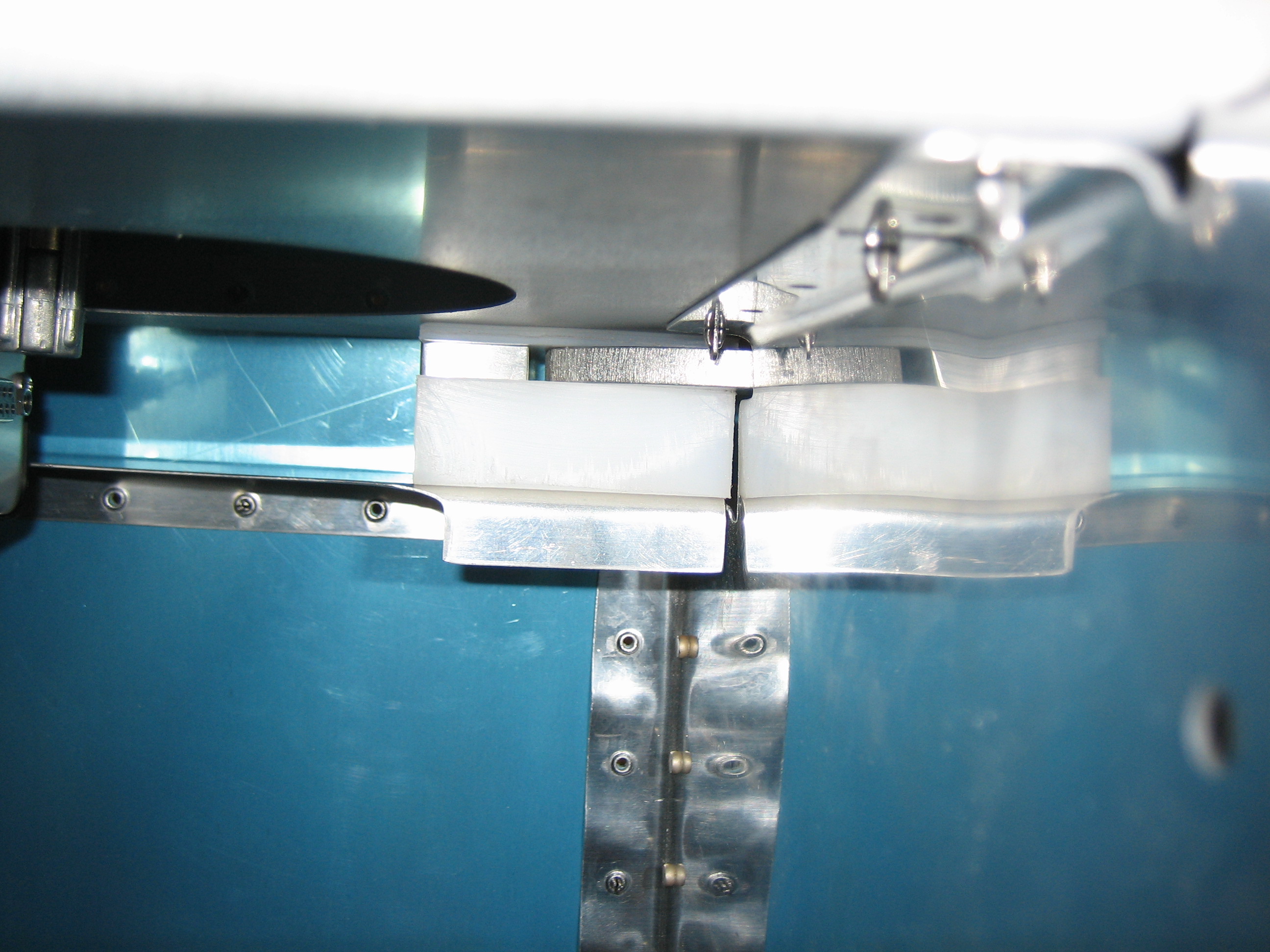
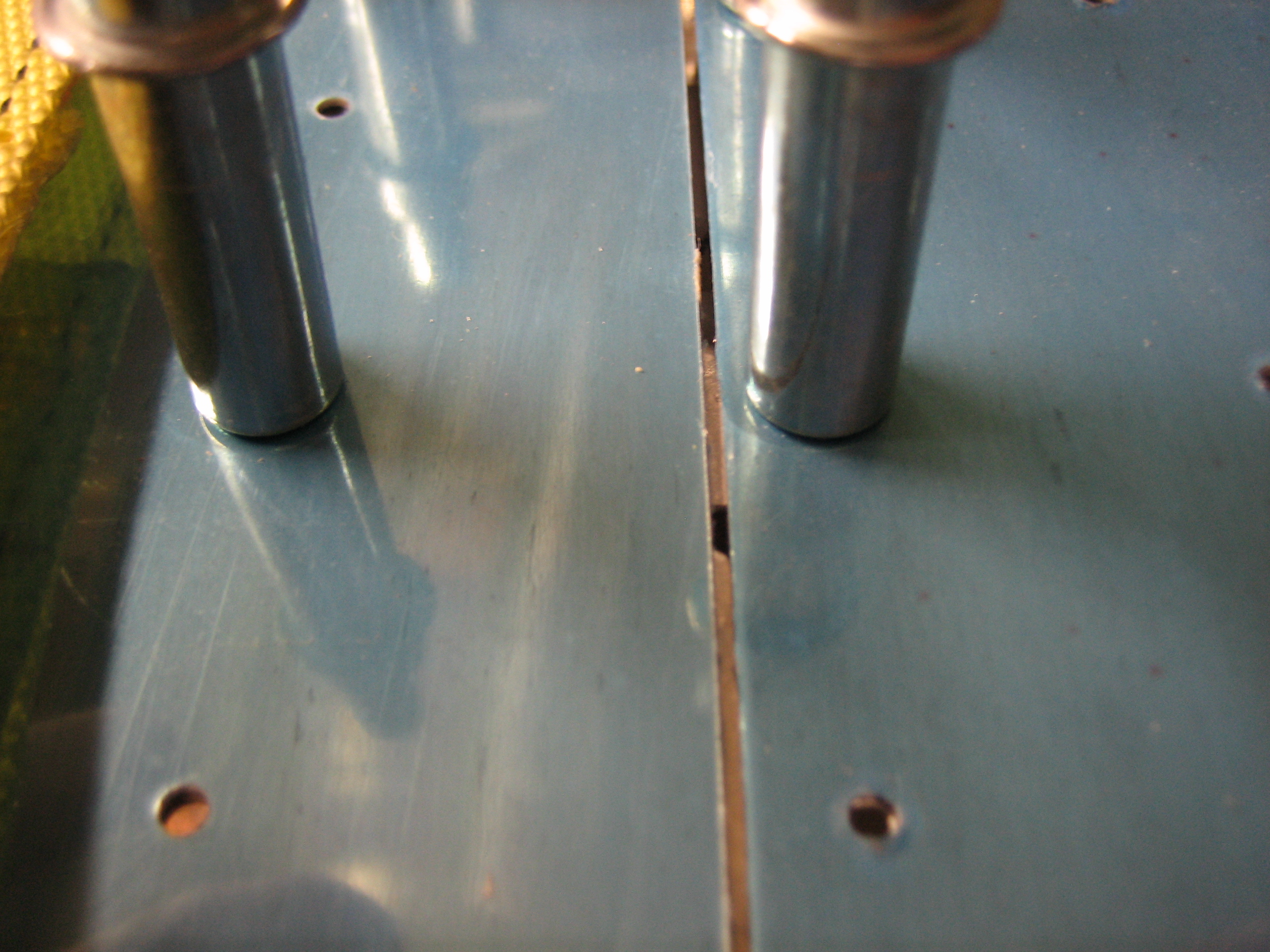
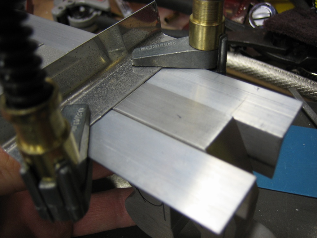
On the other side, you can see how the latch sits proud of the attach angles. This is because the attach angles will sit flush with the inside of the skin, but the latch components should be flush with the outside of the skin. The skin is 0.032″, but I positioned these currently 0.036″ proud of the angles. After I get them back from the anodizers, I’ll file the outside faces flush with the side of the plane since they’ll be painted the same color as the exterior.

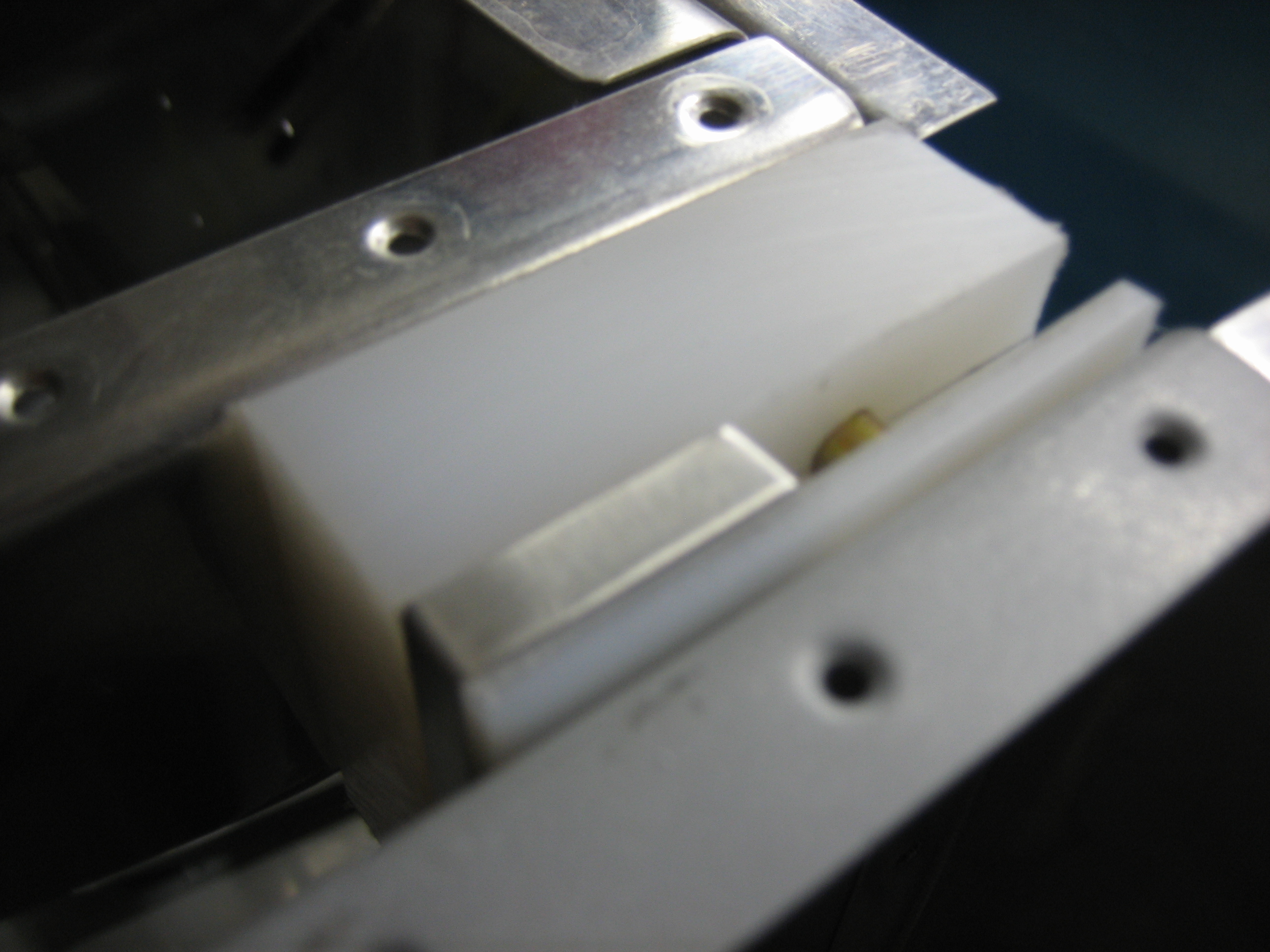
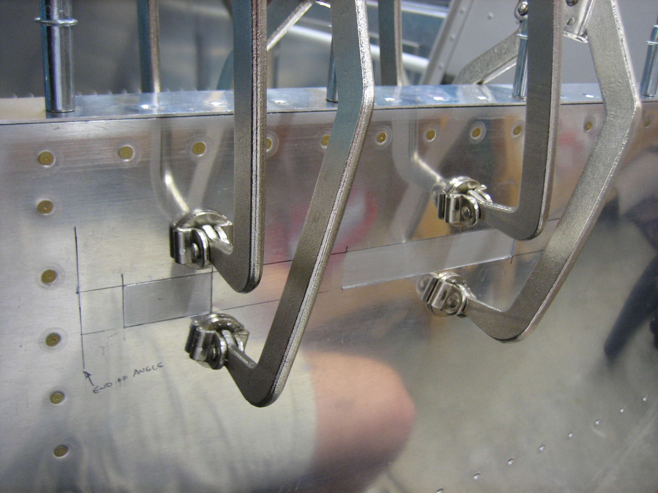
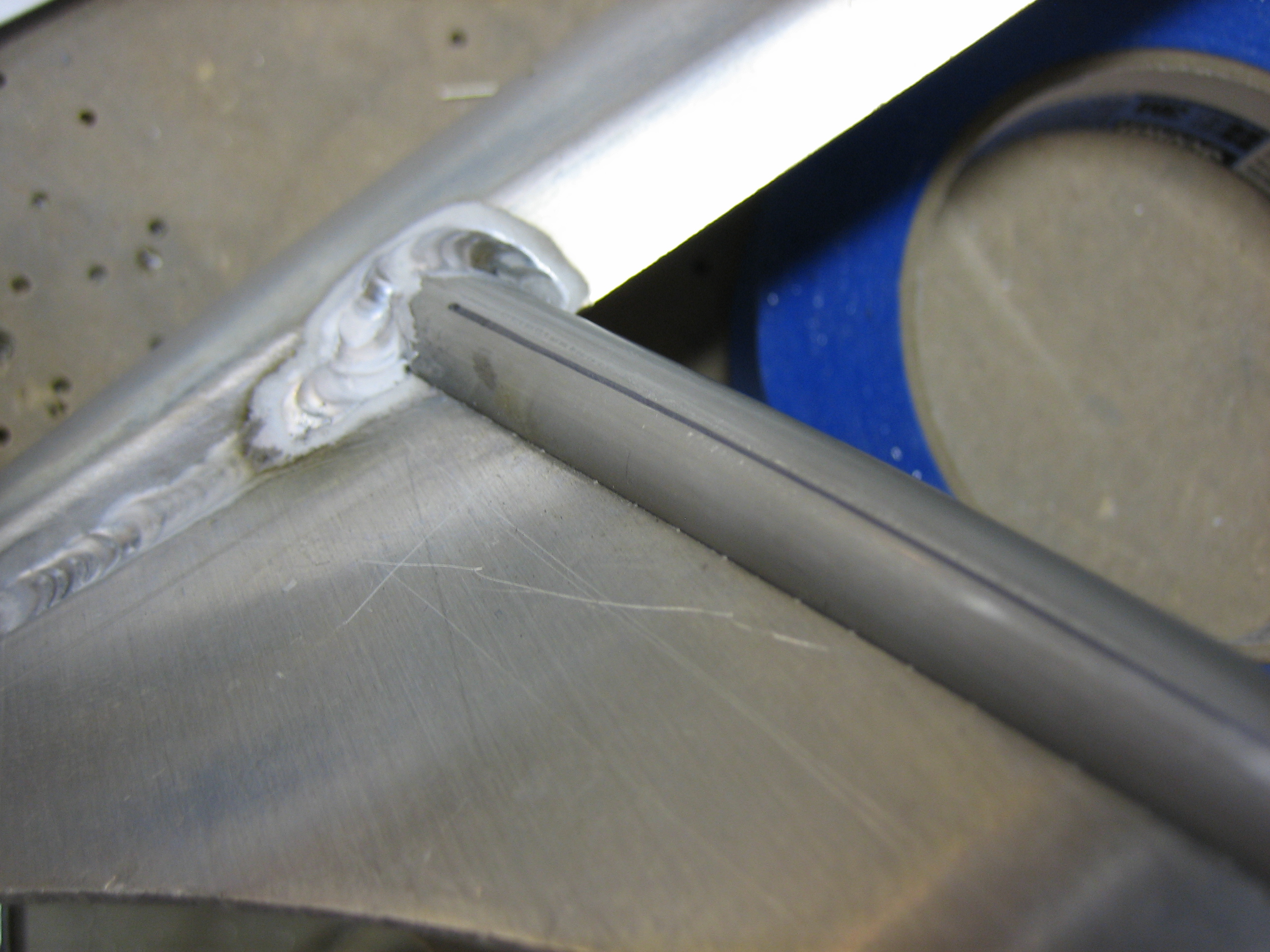
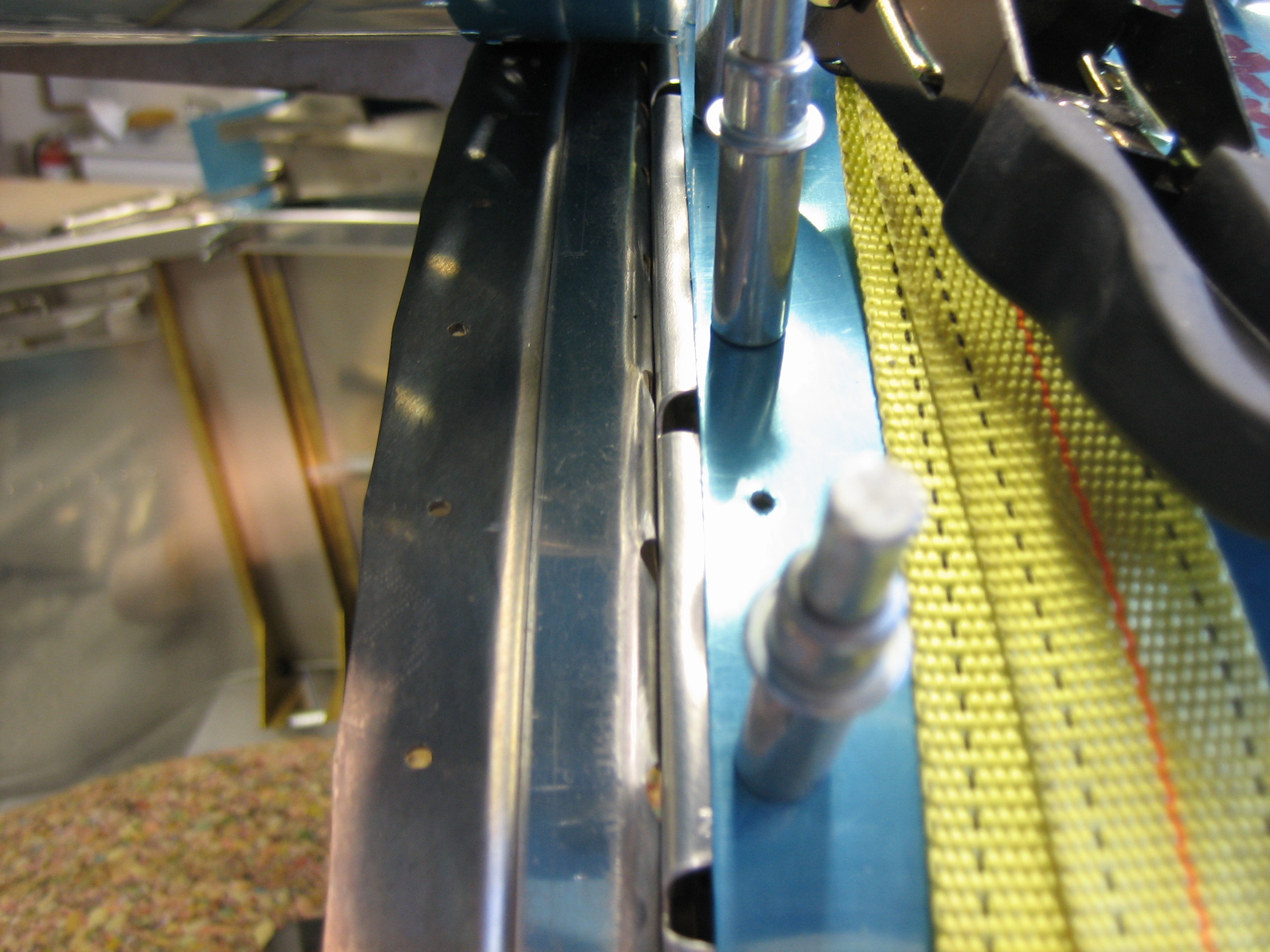
I’ve temporarily clamped a piece of scrap material across the outside face to simulate the skin since the skin acts as a stop for the forward catch.
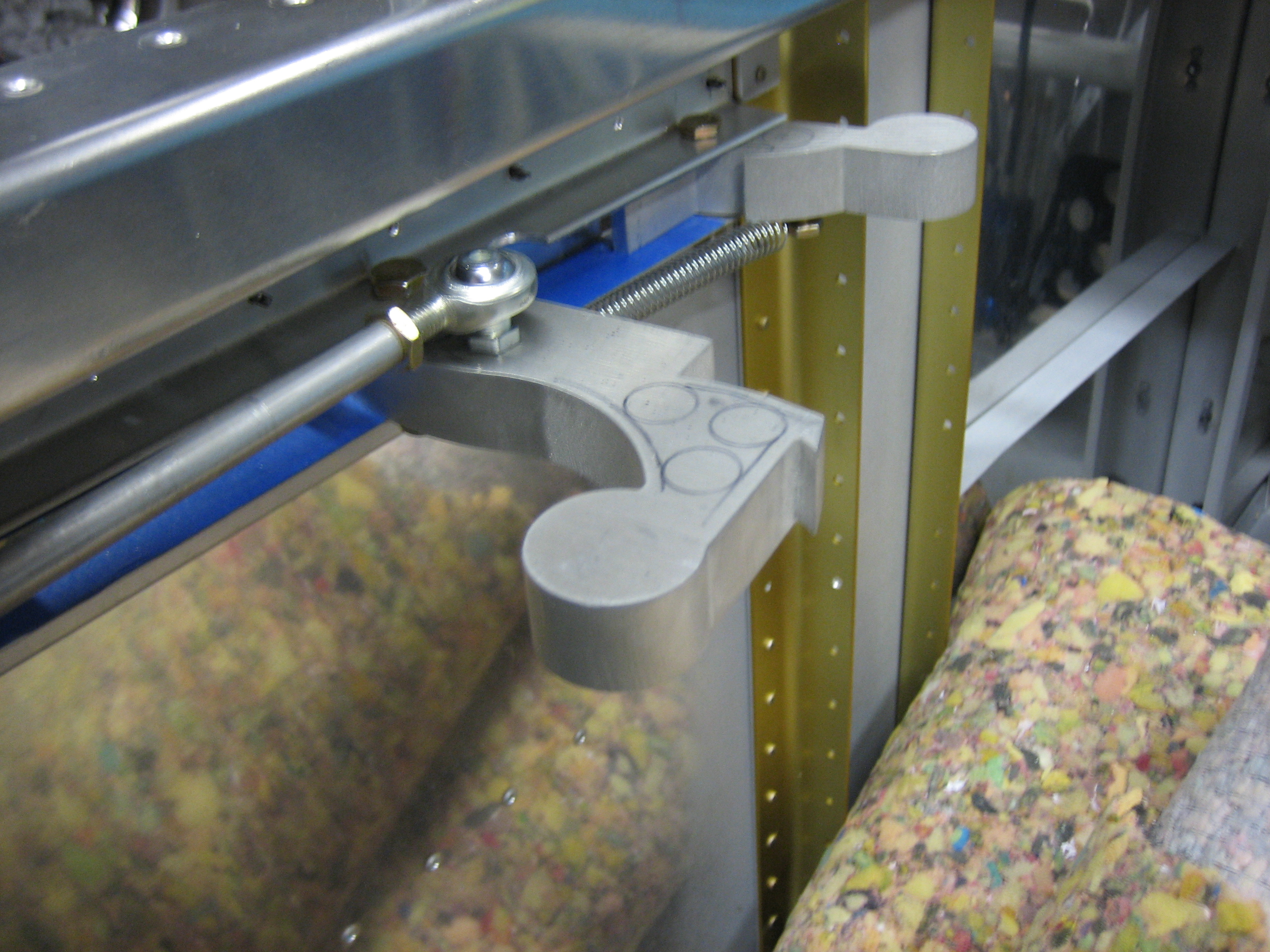
To open the latch, you push forward on the forward knob until the aft part is released.
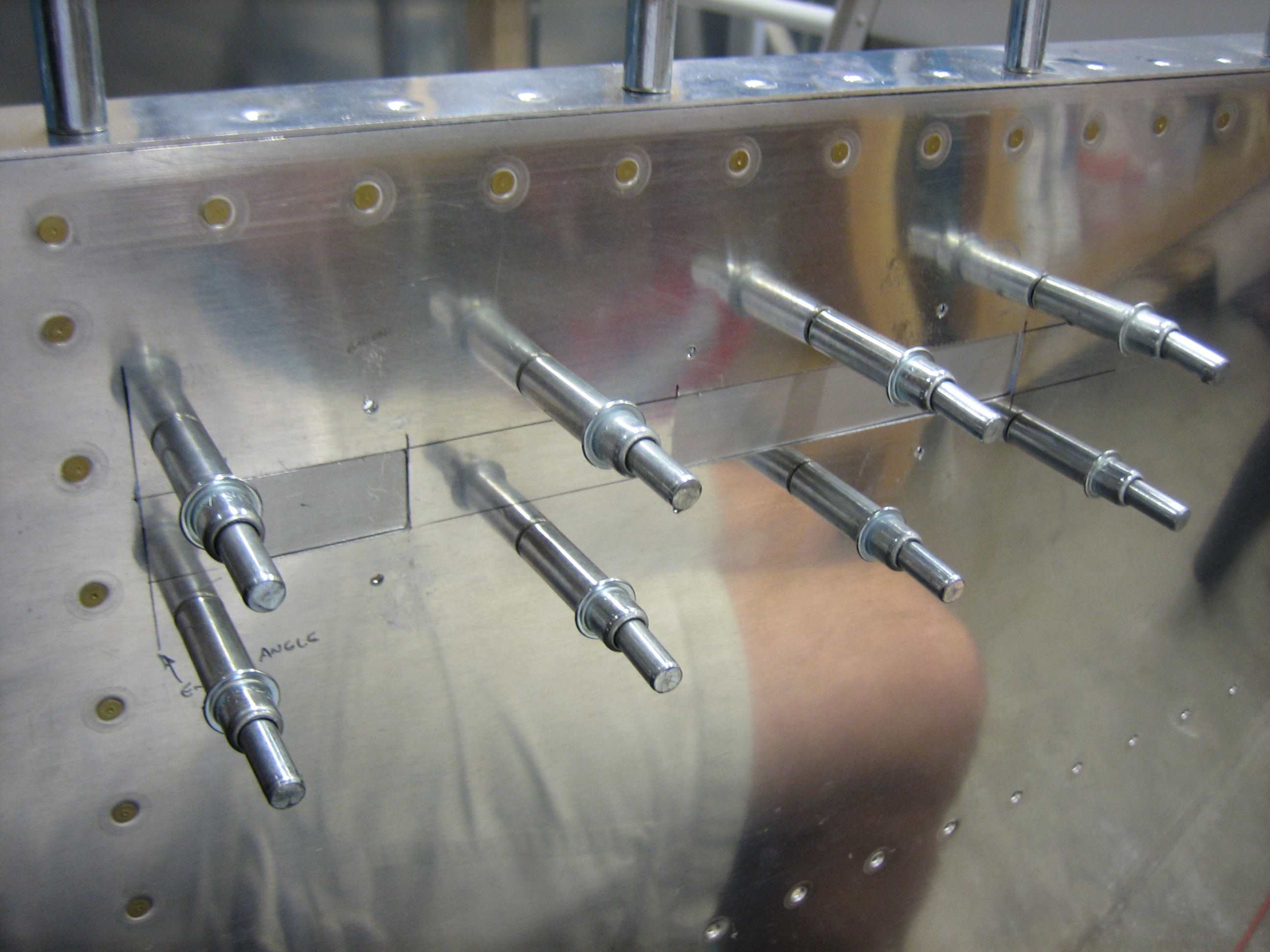
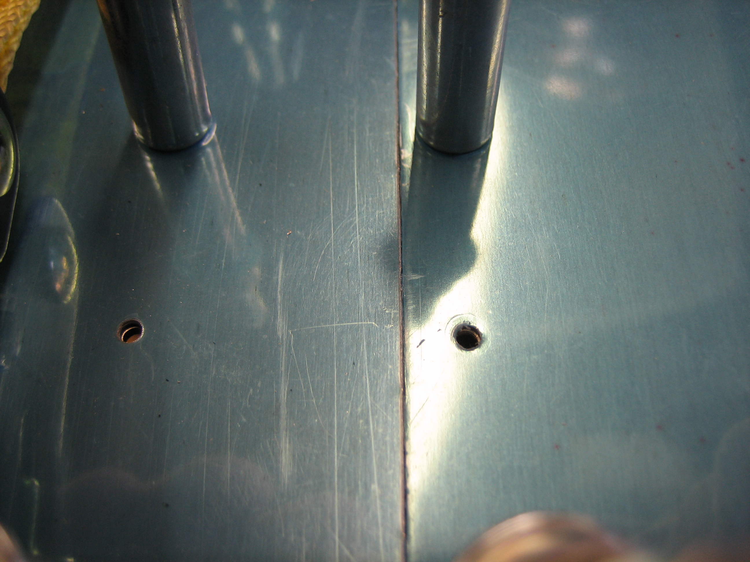
Once the latch is released, the aft part pops back.
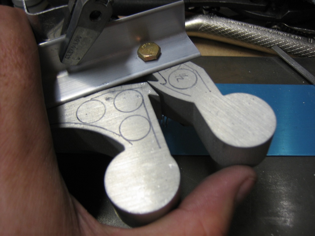
It can then be pulled aft to release the canopy.
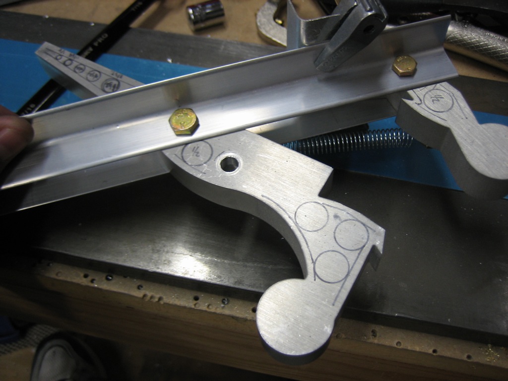
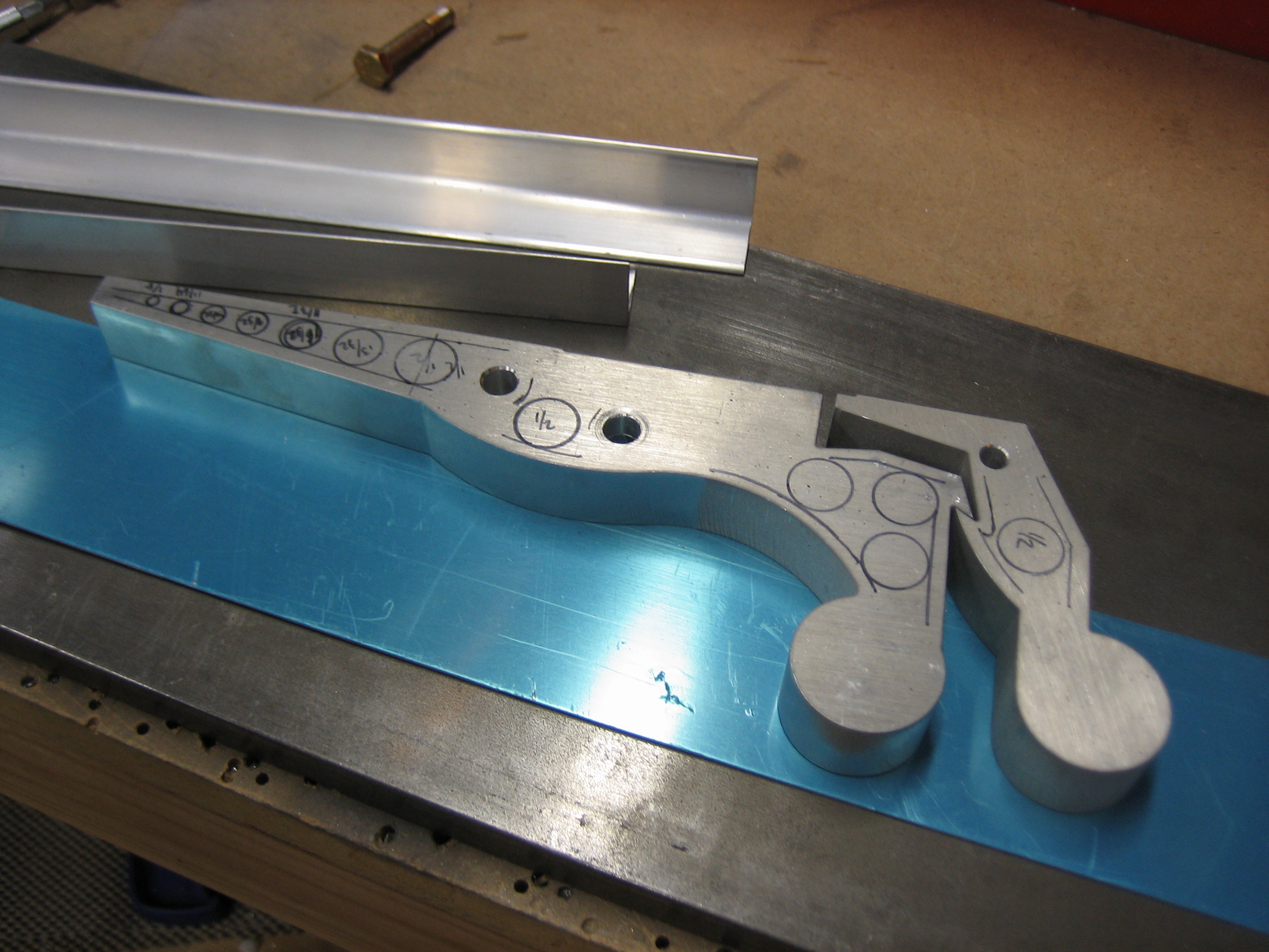
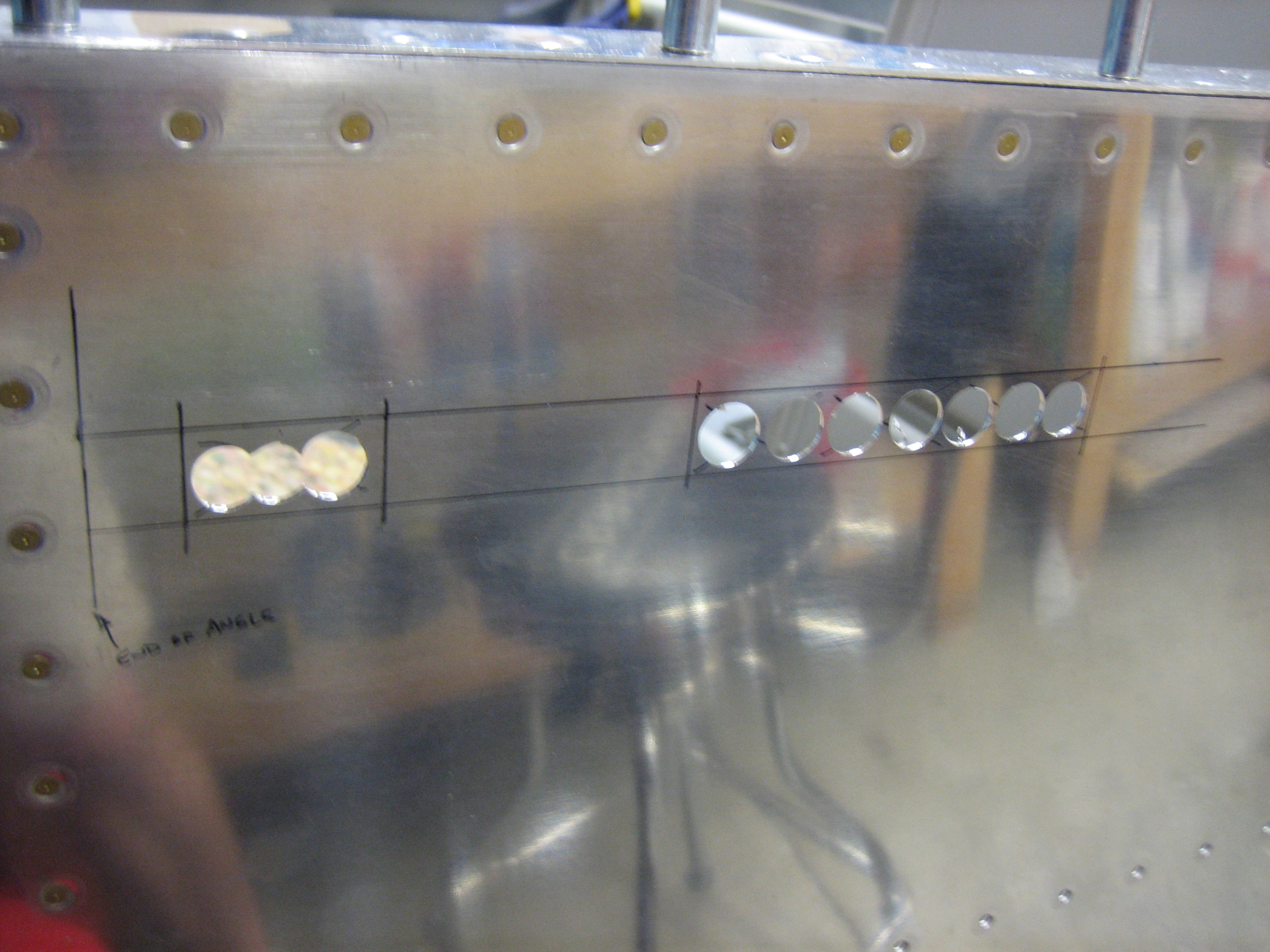
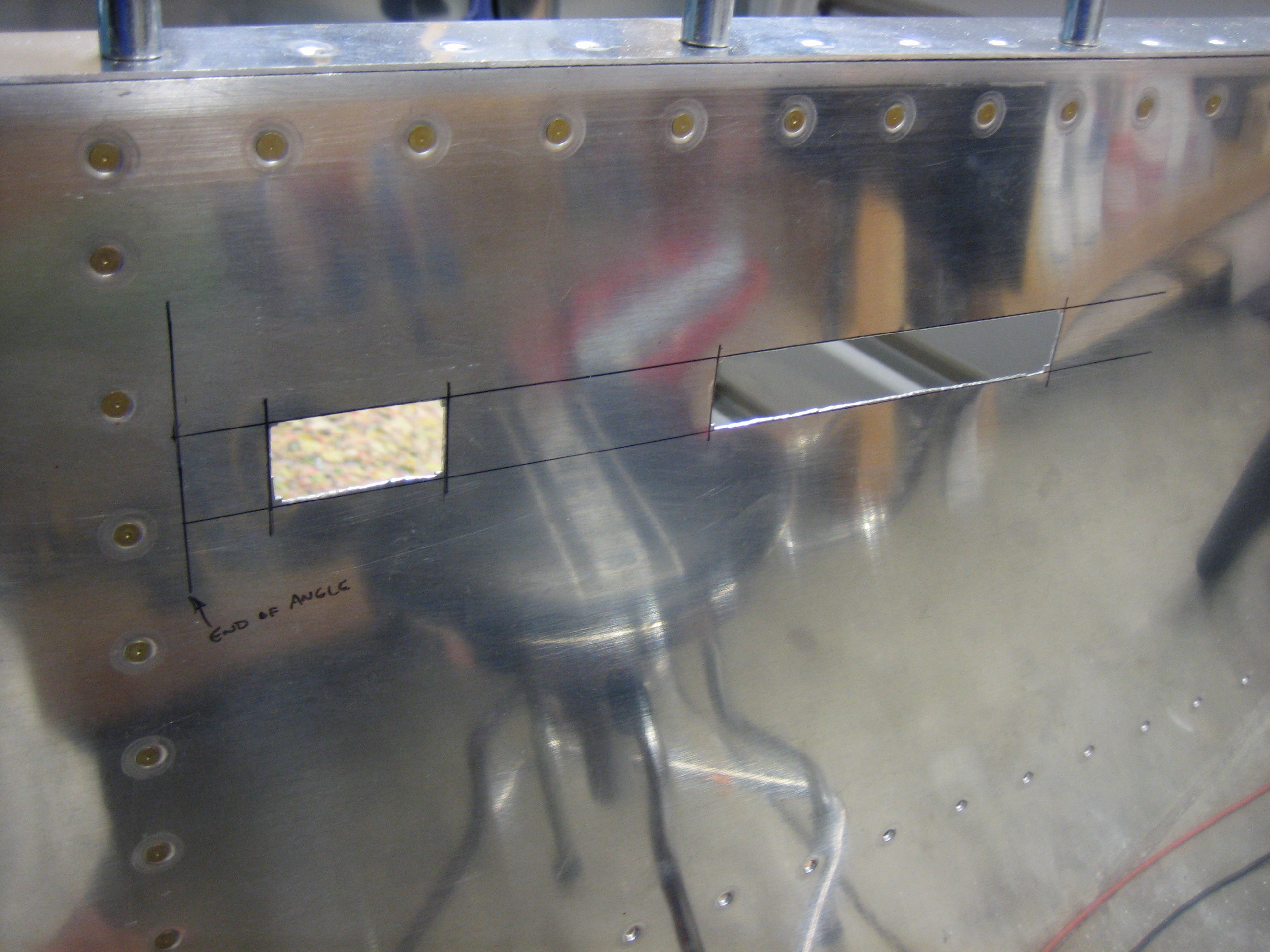
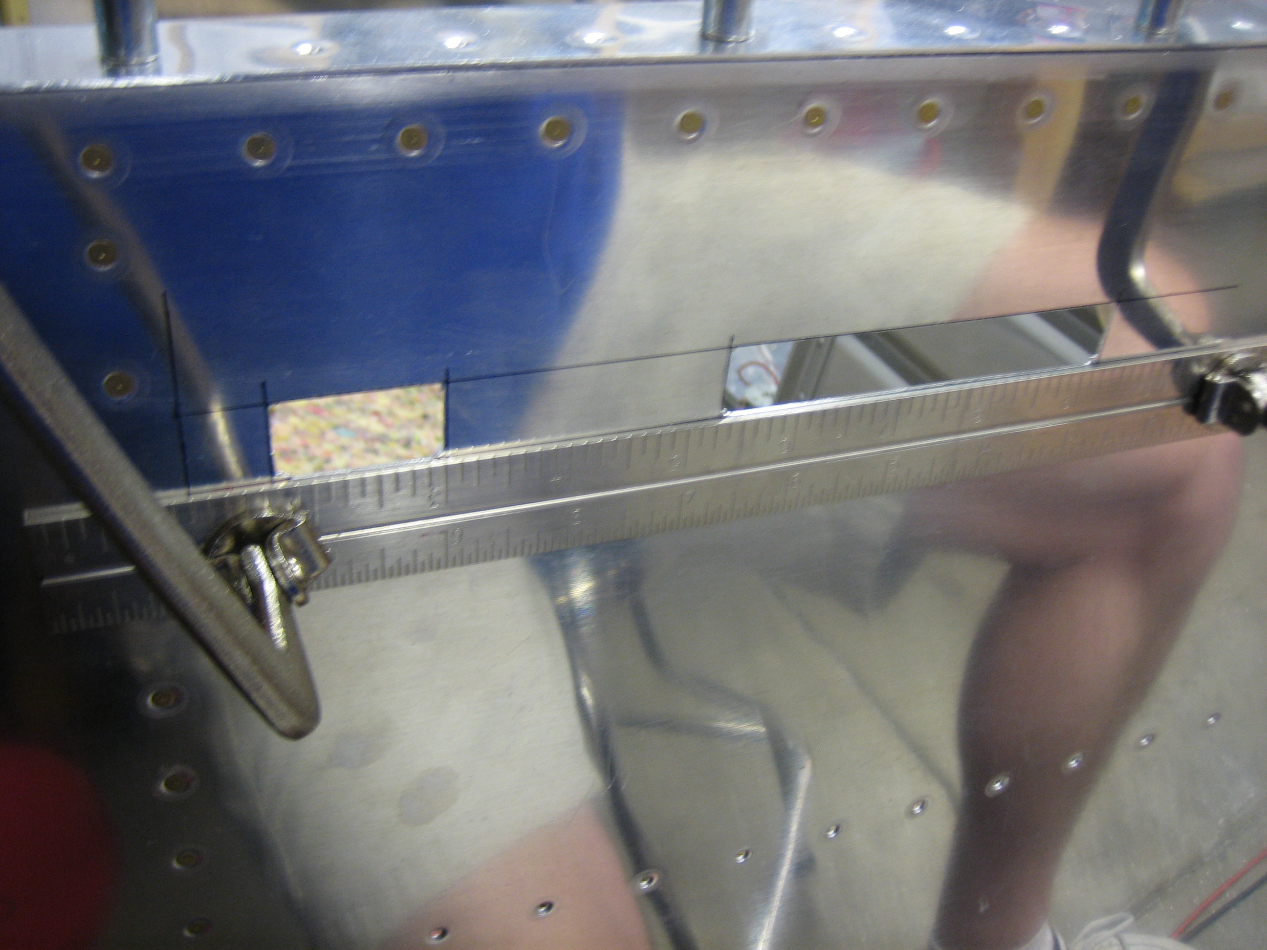
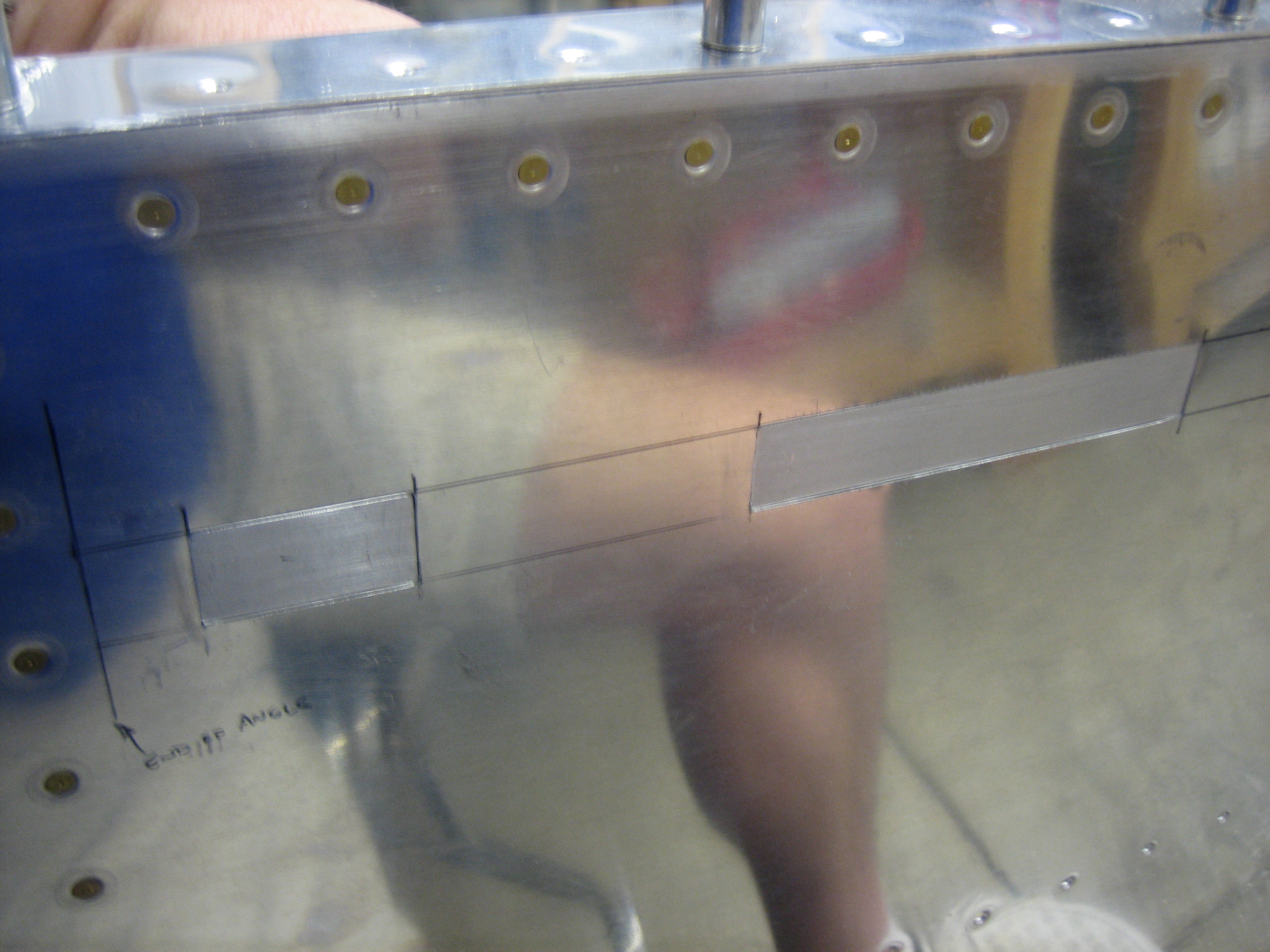
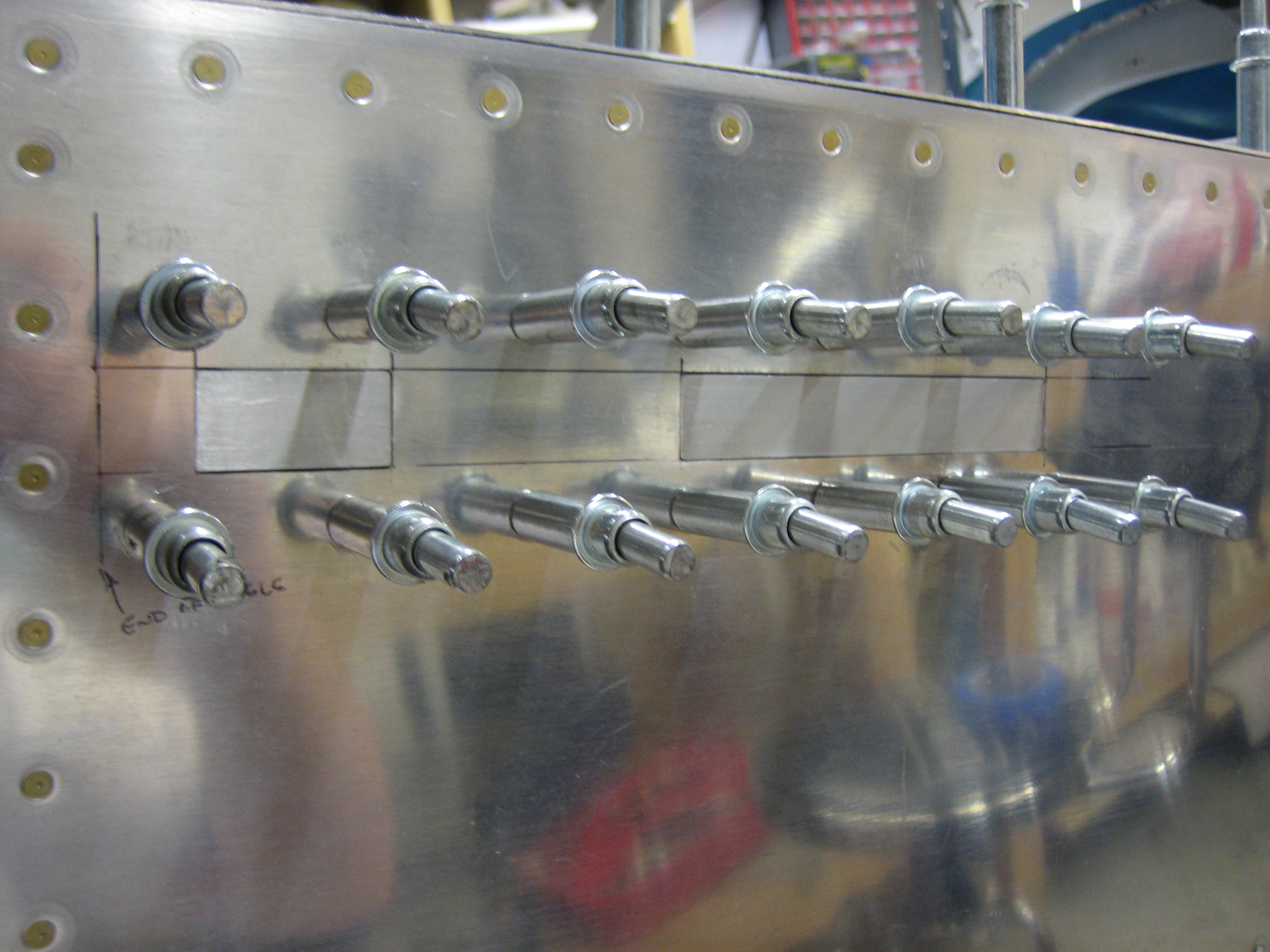
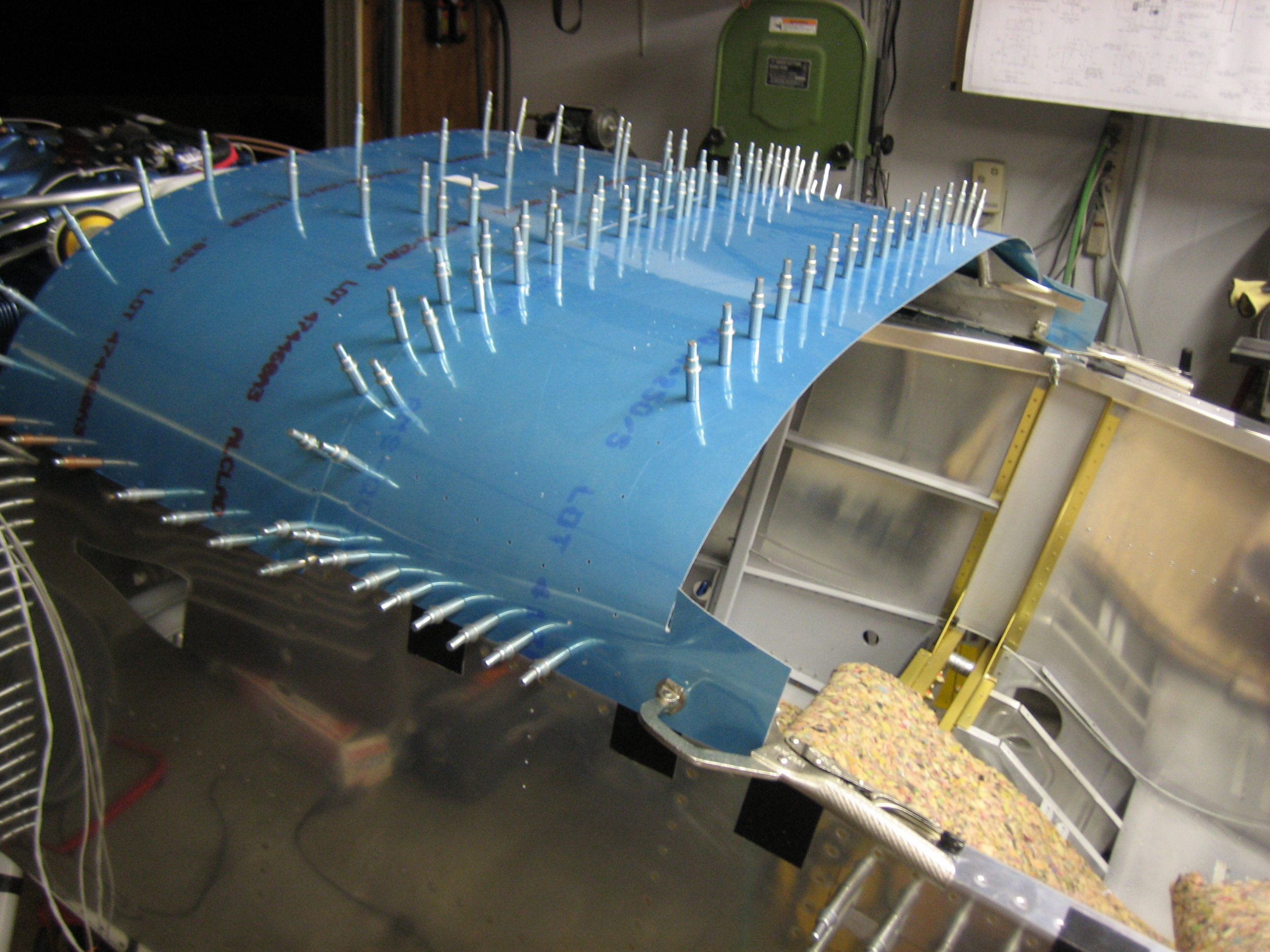
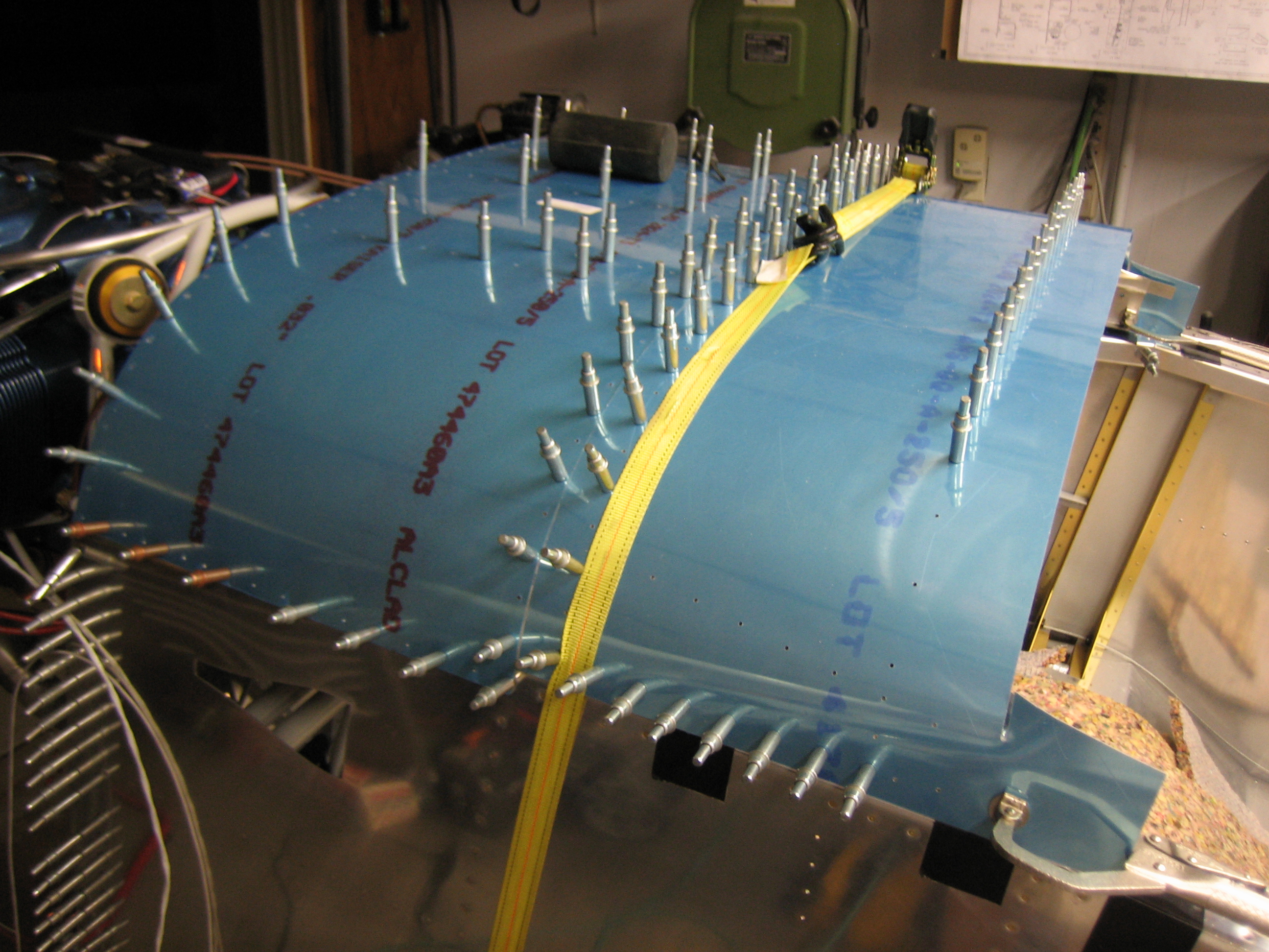
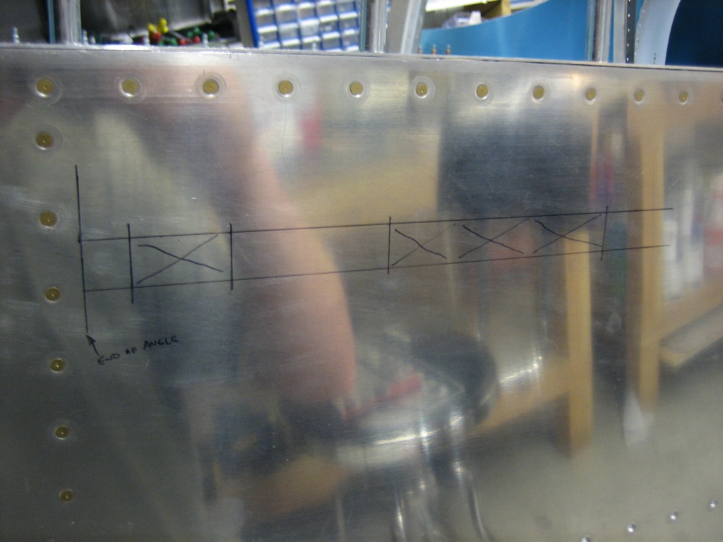
Finally, I laid out the cutout for the side skin. It’s late, and I want to do this when I’m fresh, so I’ll start this tomorrow.
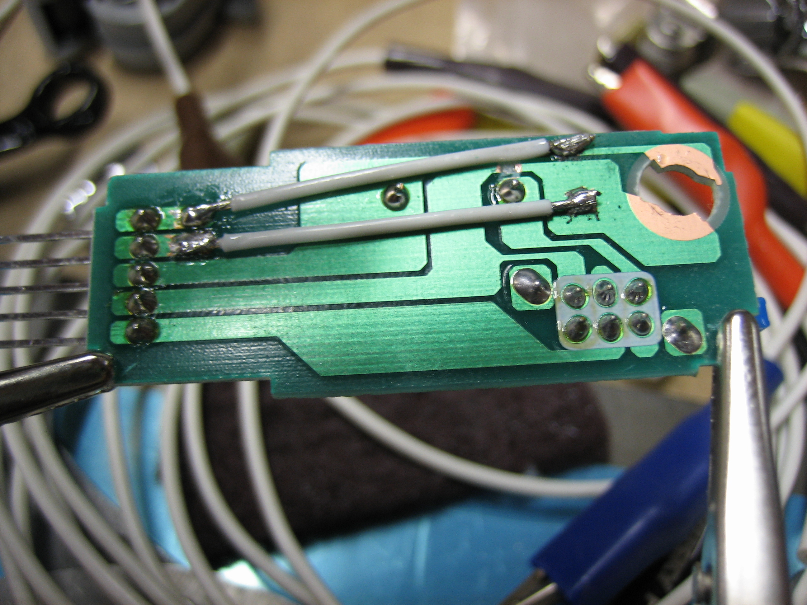
I wasn’t completely tired, so I wanted to figure out how the engine start switch will be wired. I don’t think I’ve mentioned it before, but I’m using the engine start switch from a Honda S2000. It has an integral light, but it’s really dim and can’t be controlled separately from power to the switch.
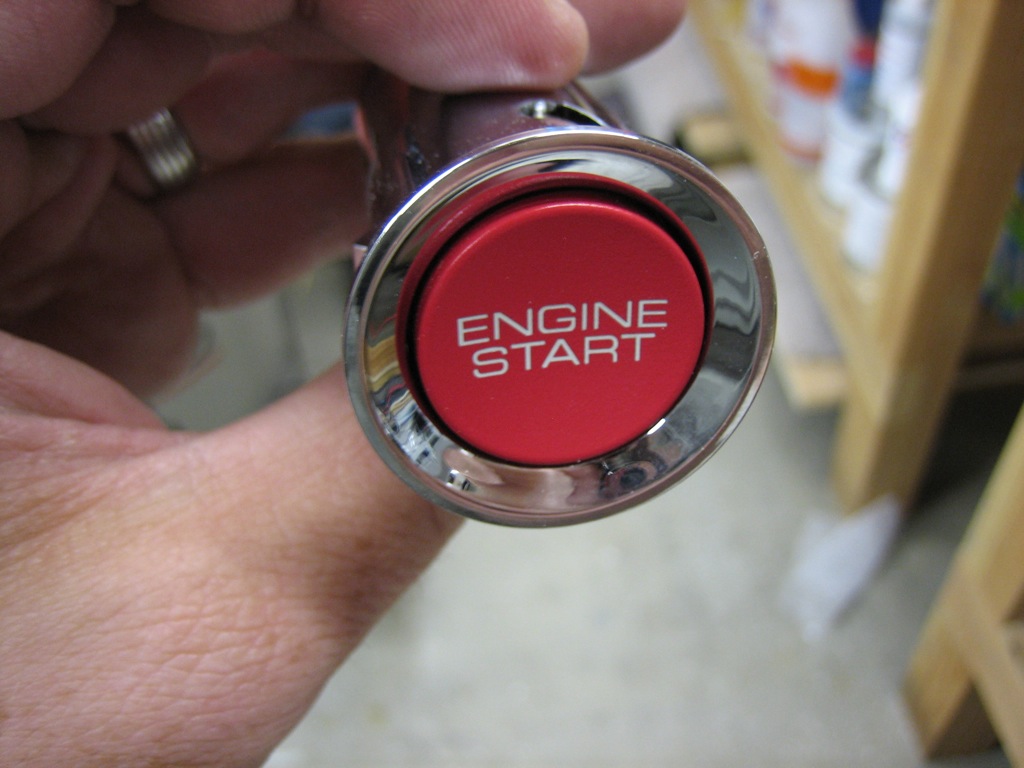
To solve this, I disassembled the switch, cut the traces to the light and wired them to the two unused pins on the connector. If I end up using the Vertical Power VP-X, it can turn on the light when the start button is enabled. I think I’m going to have to use a relay between this switch and the starter relay since I’ve heard the starter relay pulls about 4 amps and I don’t think this switch can handle that kind of current. I need to confirm this though.