Installed Princeton Capacitive Fuel Senders

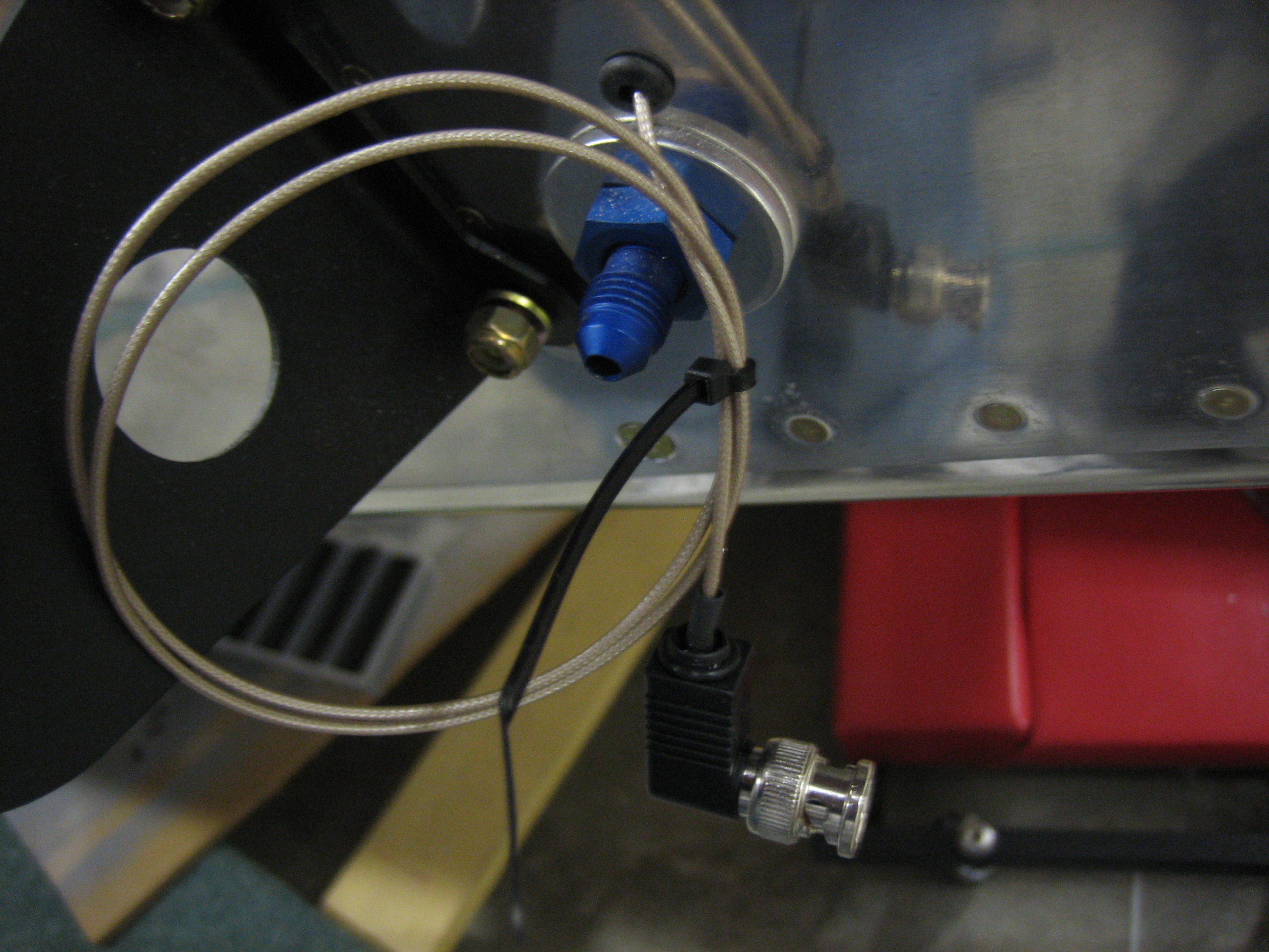
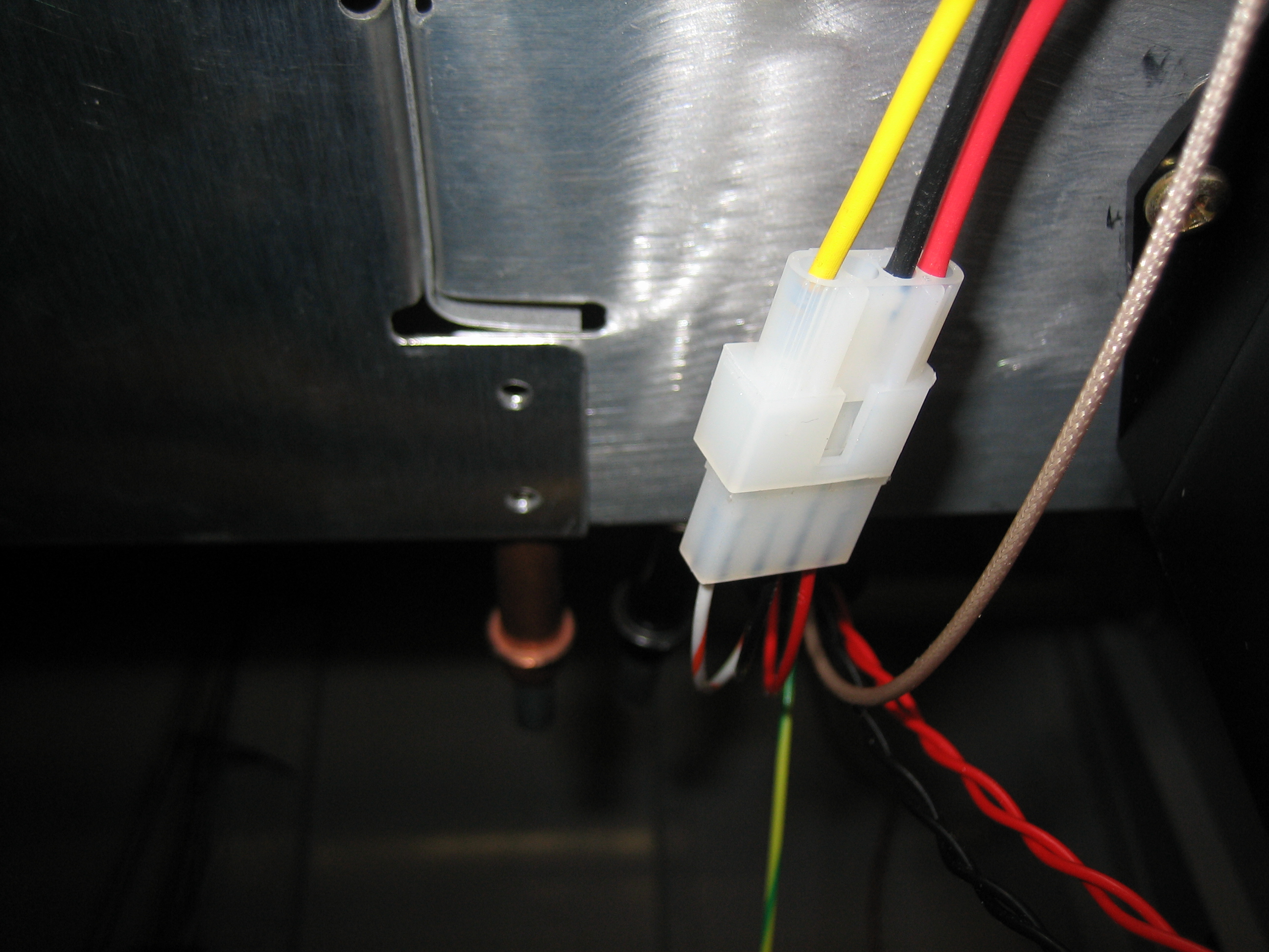
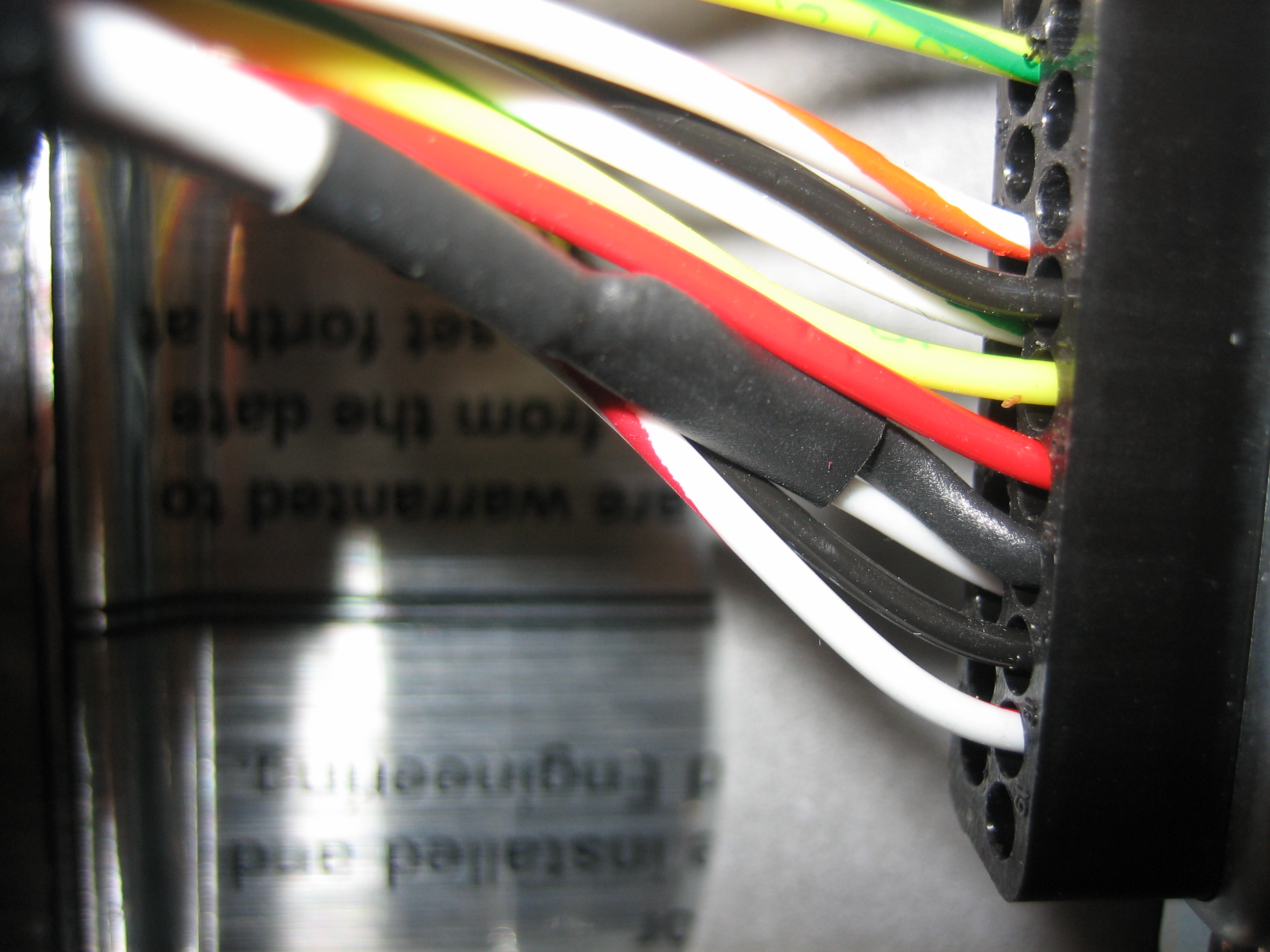
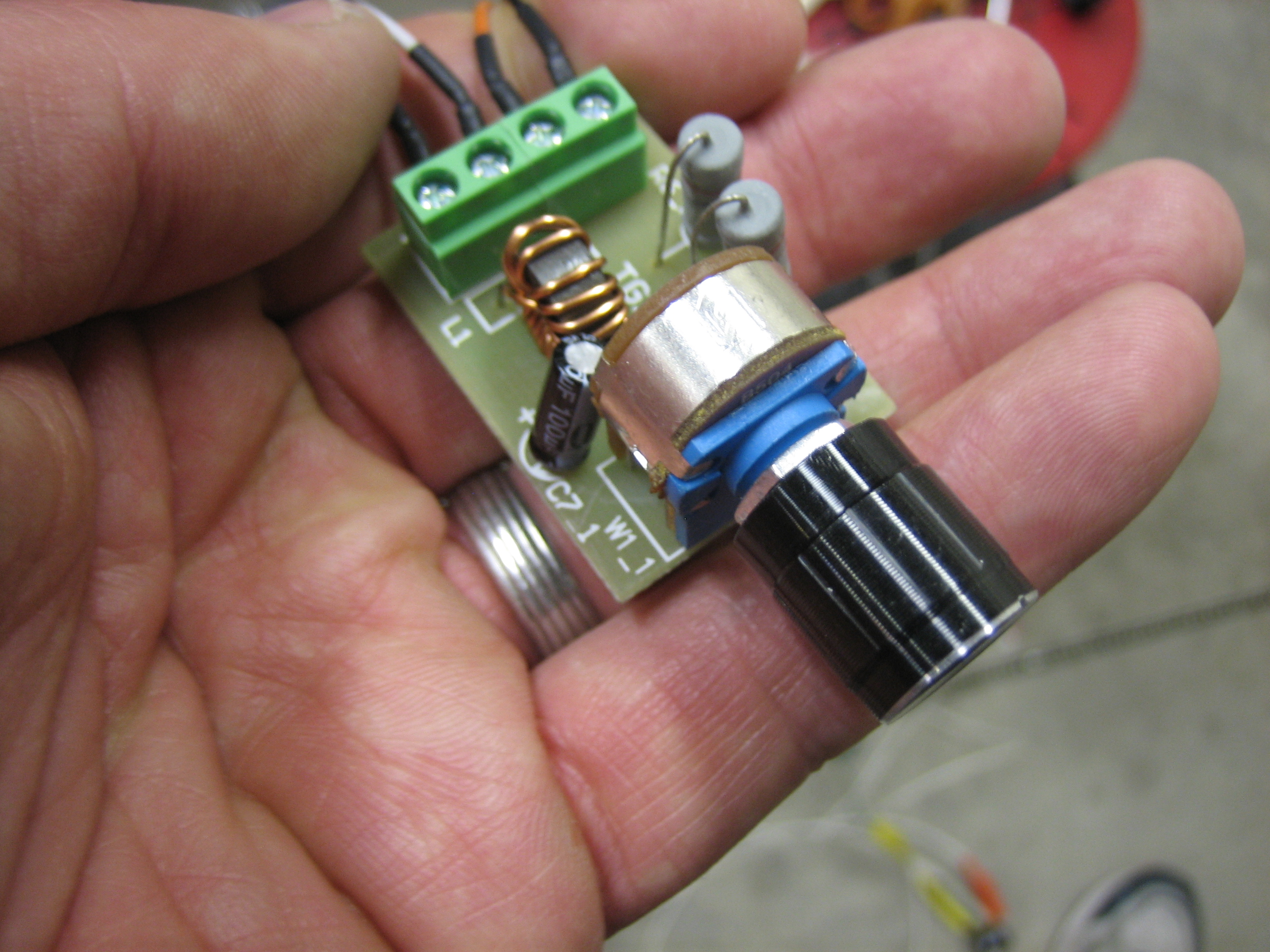
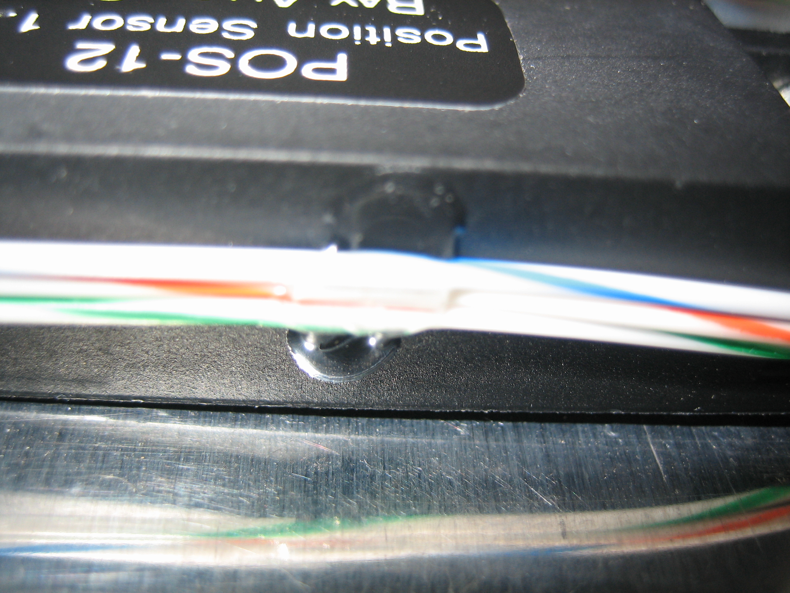
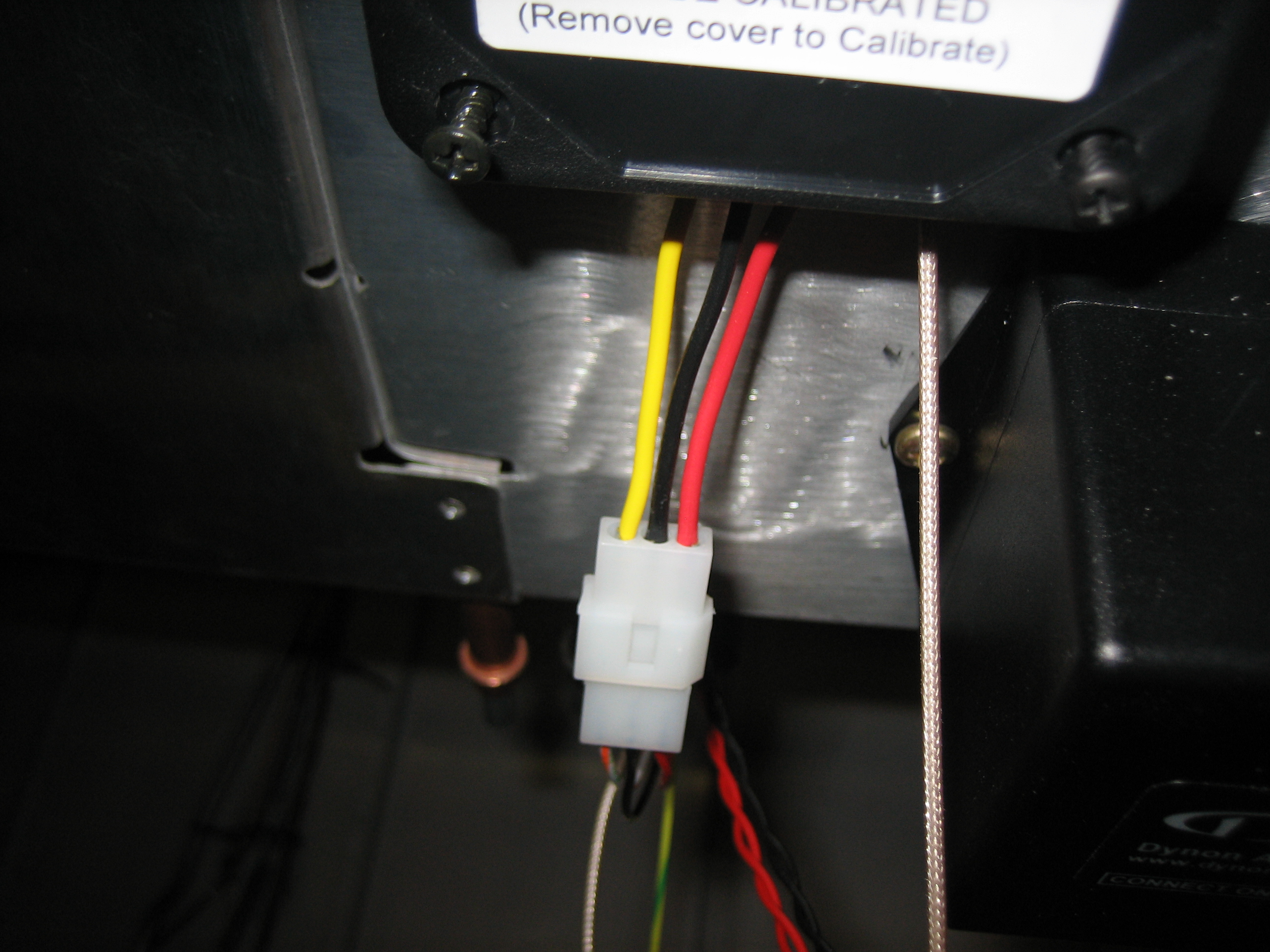
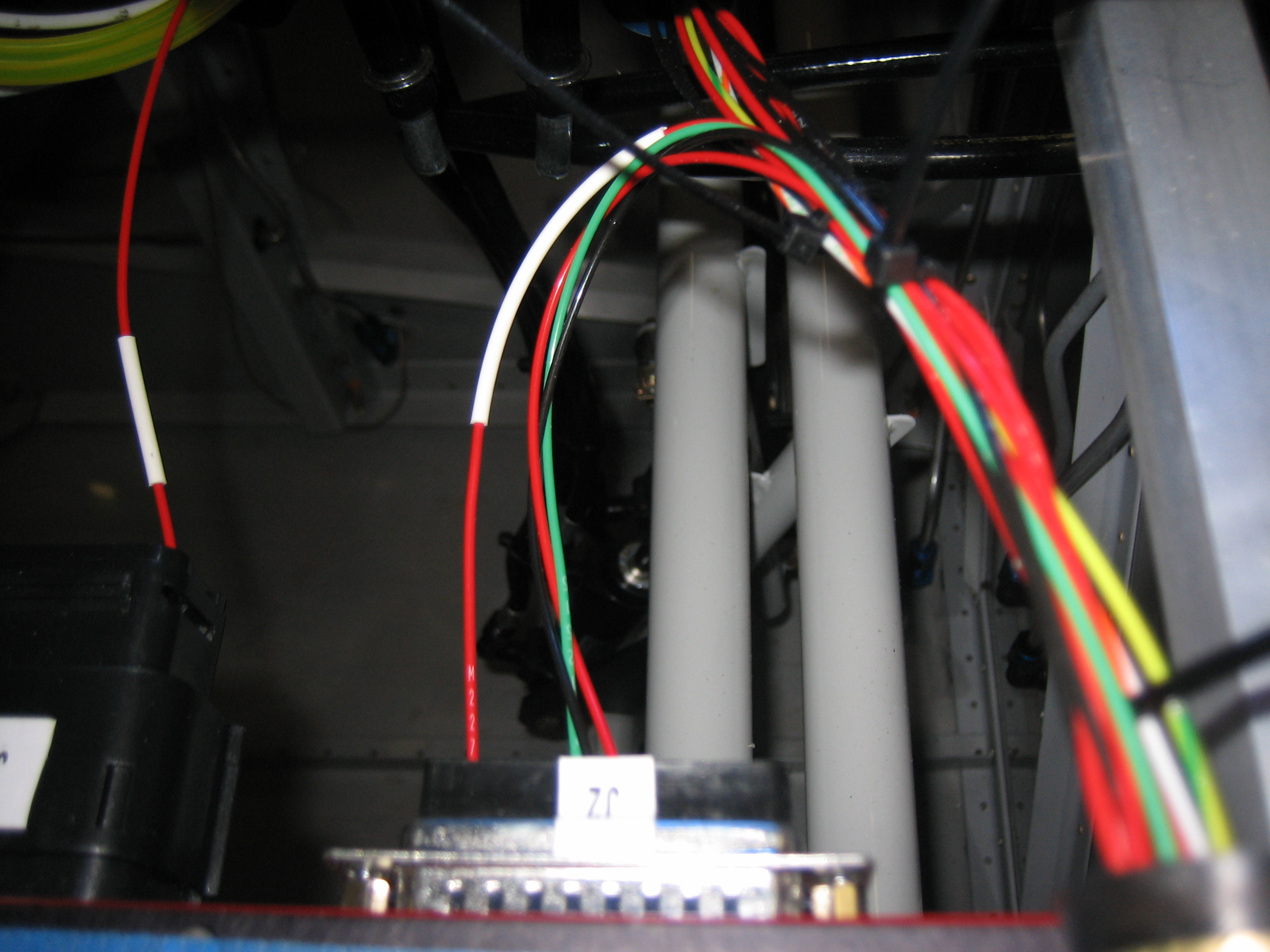
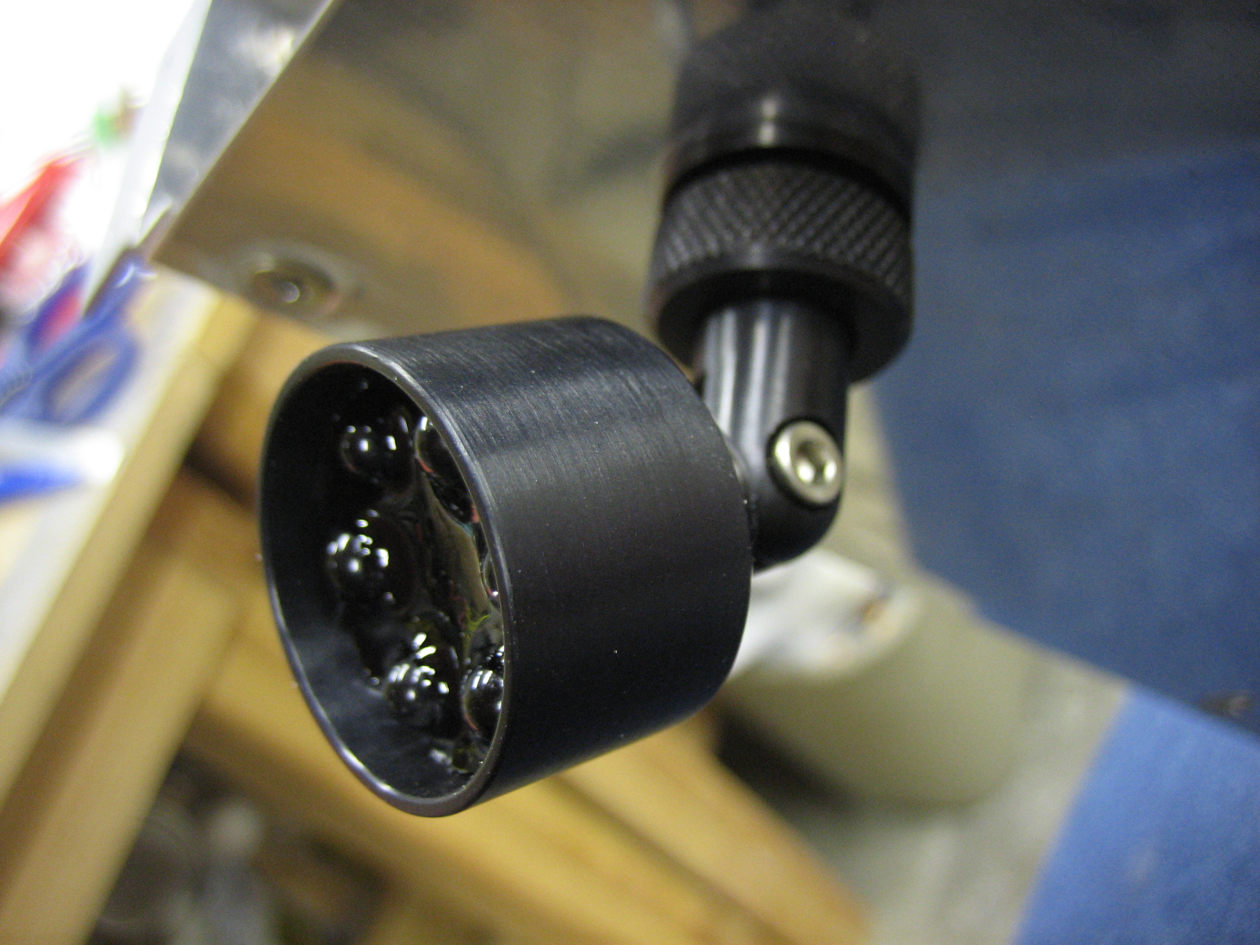
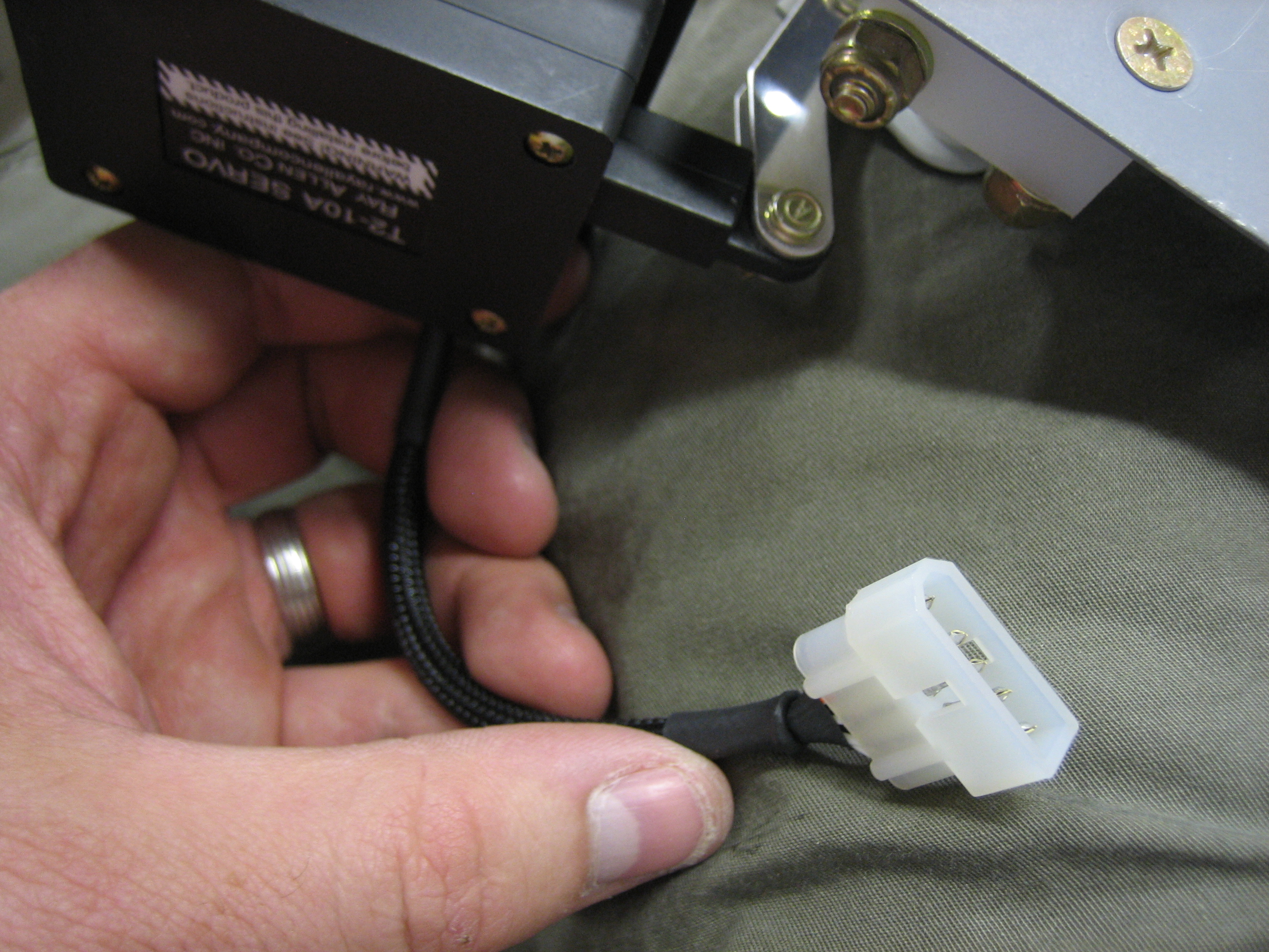
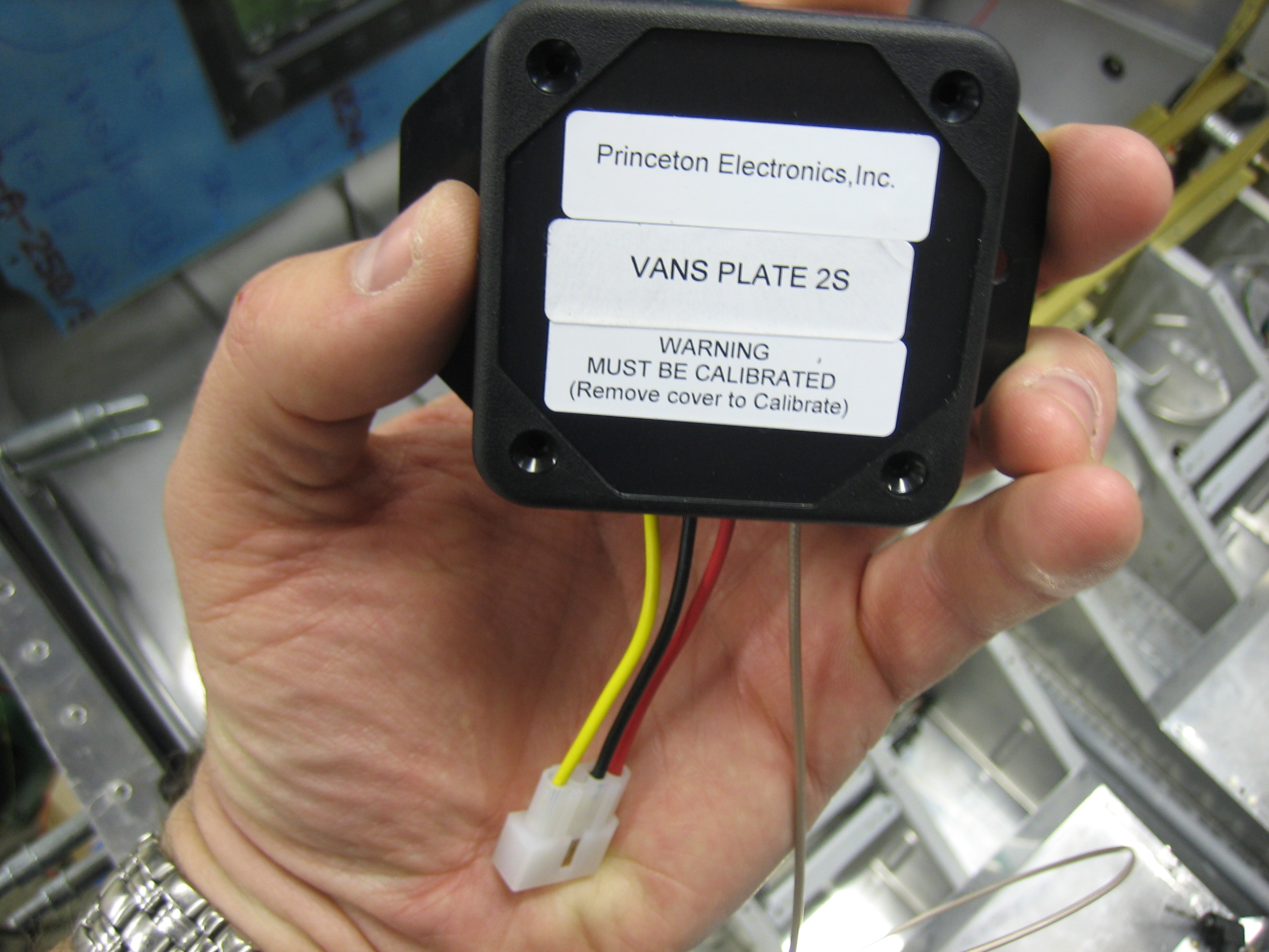
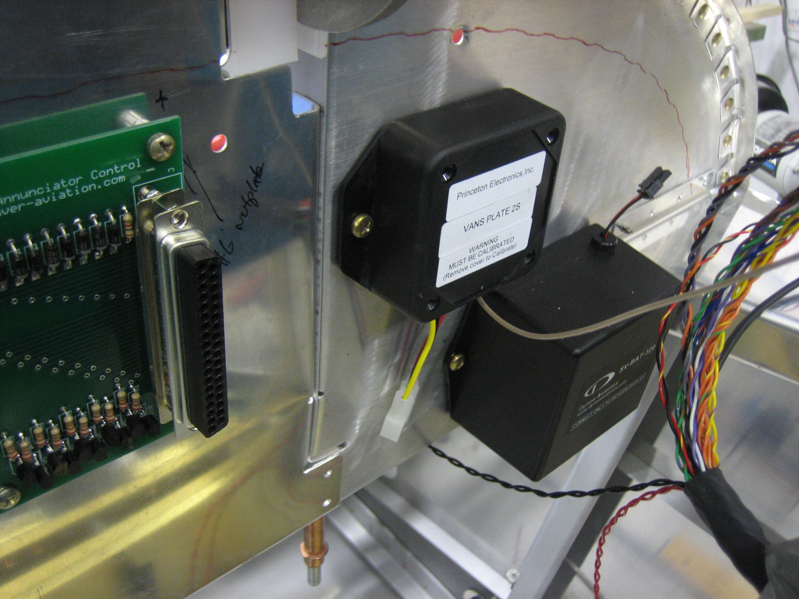
I received my capacitive fuel senders from Princeton Electronics.  They don’t have a website, but you can reach them at (616) 243-8800.  They have both 2 level and 5 level senders.  Both convert the capacitance range from 0-5 volts, but the 2S model only has calibration points for empty and full.  The 5S model has three intermediate points which is important if you want a linear movement on an analog gauge.  Since I’m using the SkyView which has numerous intermediate calibration points, it doesn’t matter if the sender is linear or not, so I’m just using the 2S sender.  I cut most of the wires off and installed some four position molex connectors on each sender so that they can be easily removed if necessary (well, except for the cable with the BNC connector).

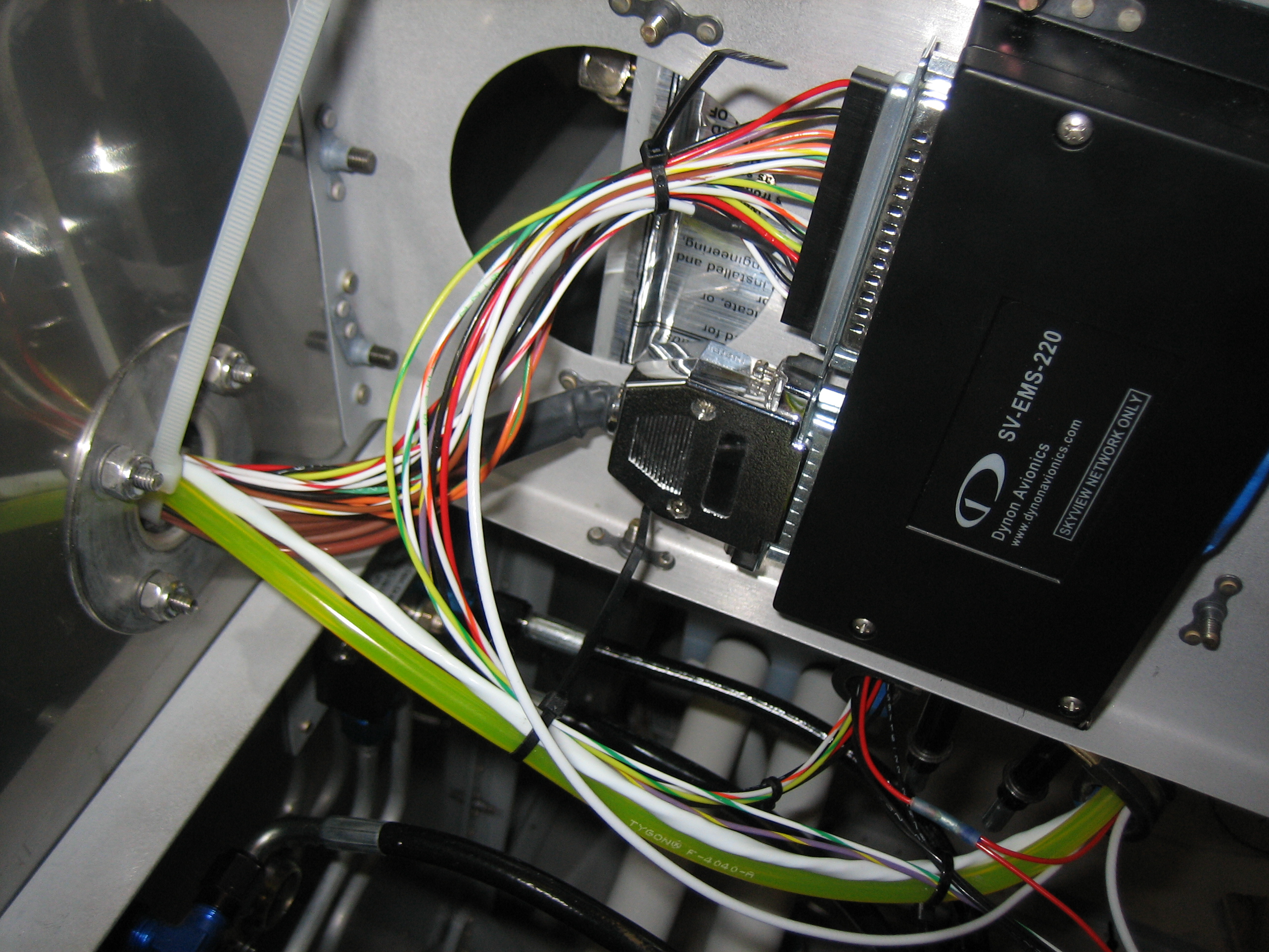
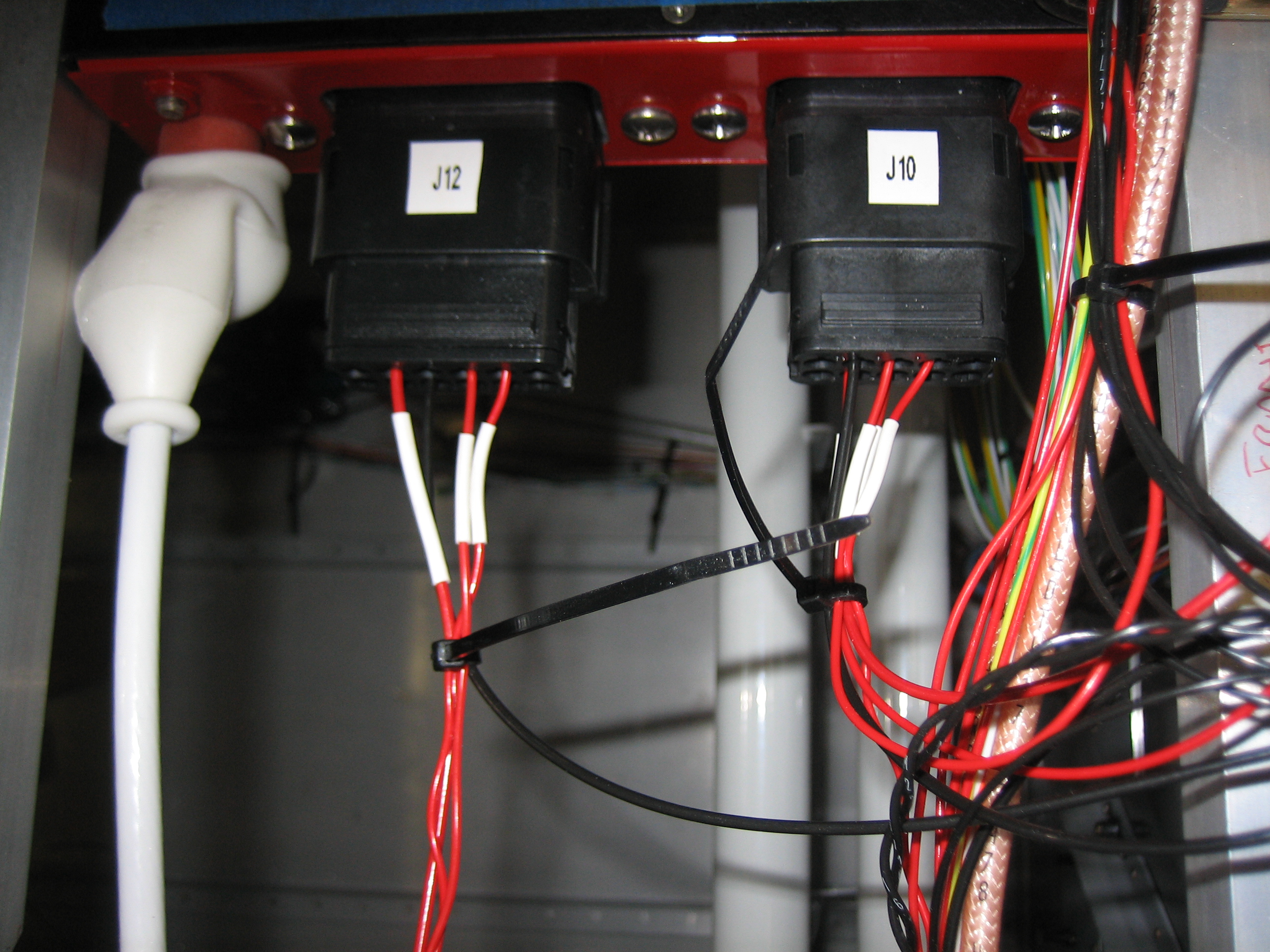
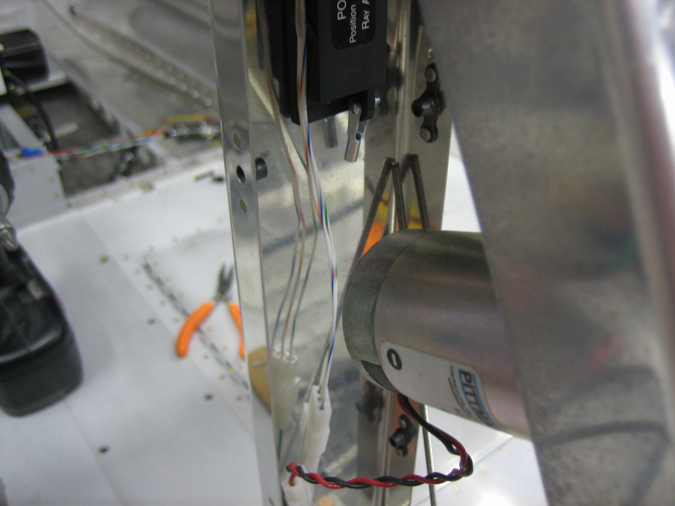
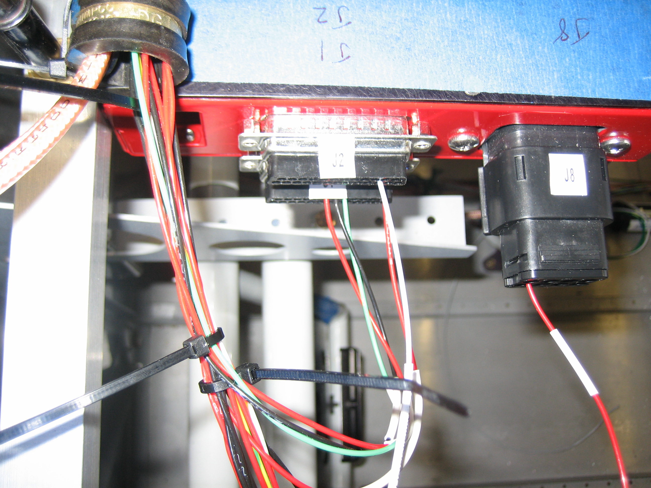
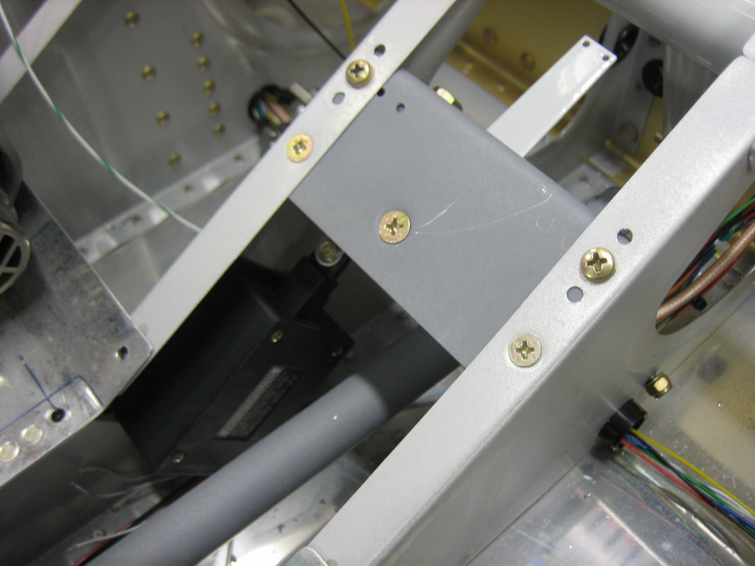
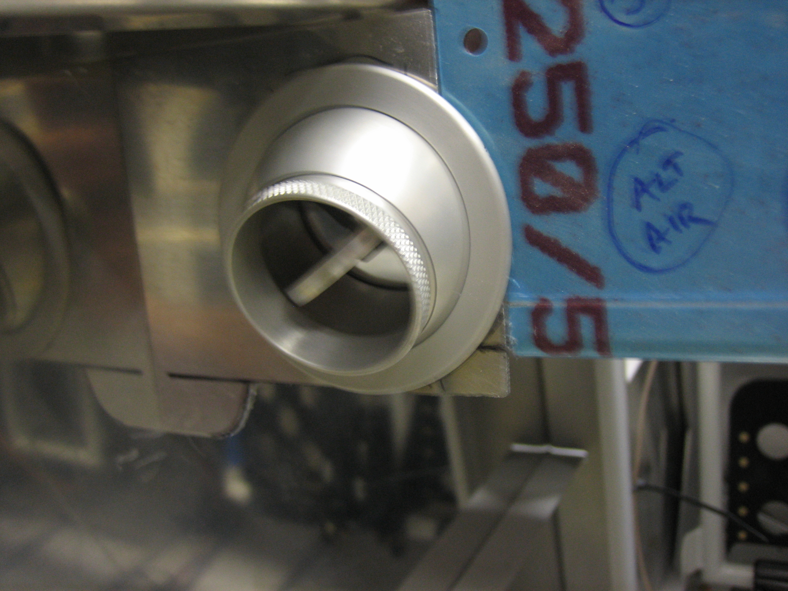
I installed the senders on the aft side of the subpanel since they need to be accessed during calibration.  This is the left sender.

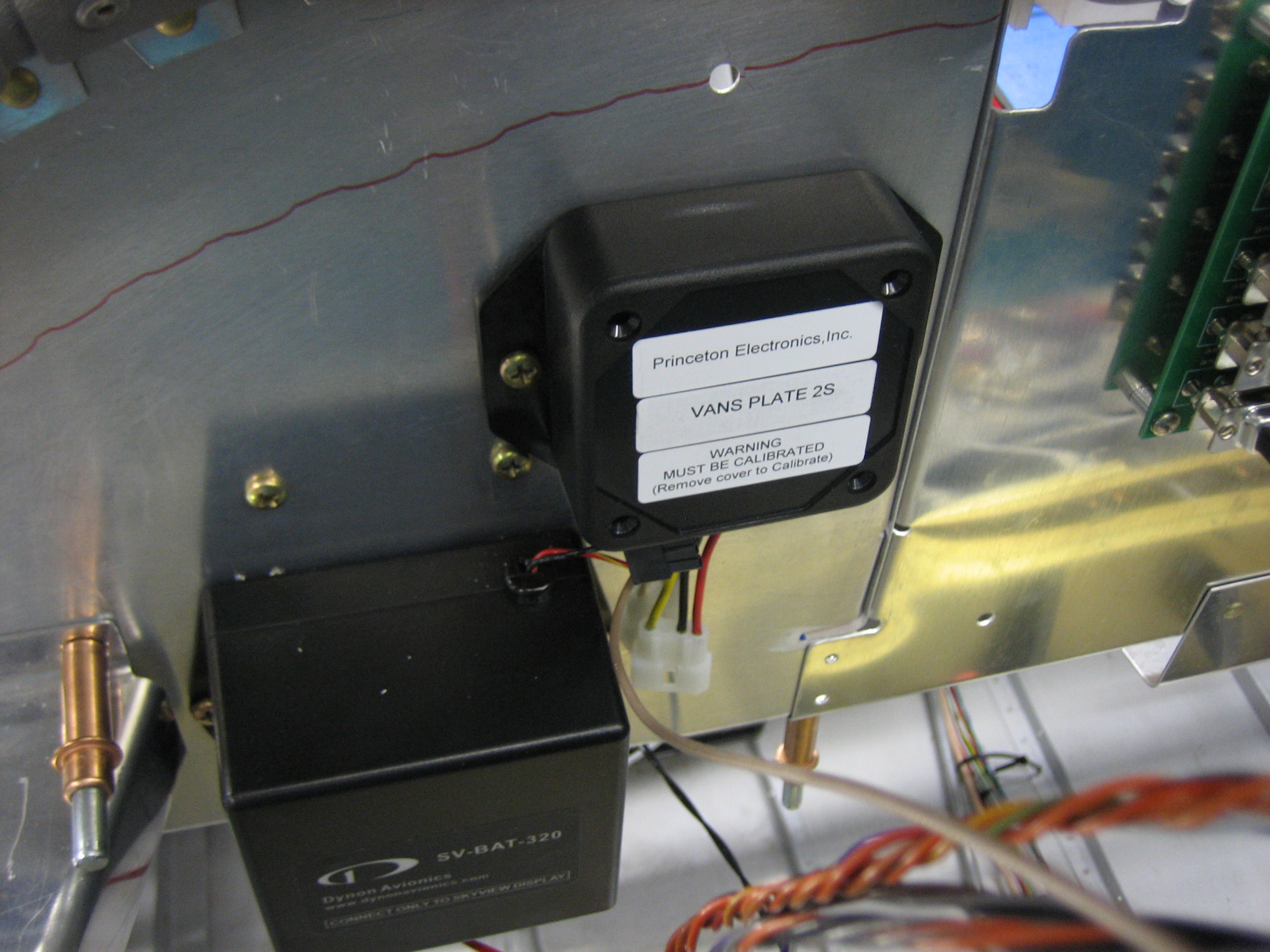
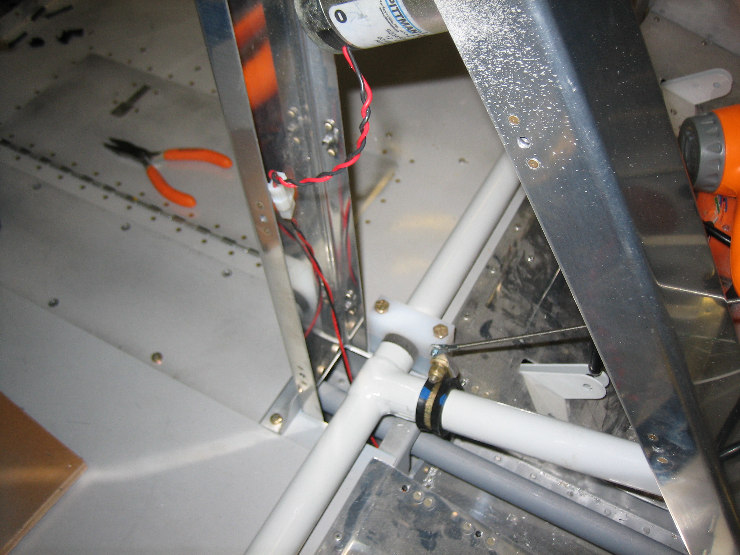
The right one is in the same relative position.

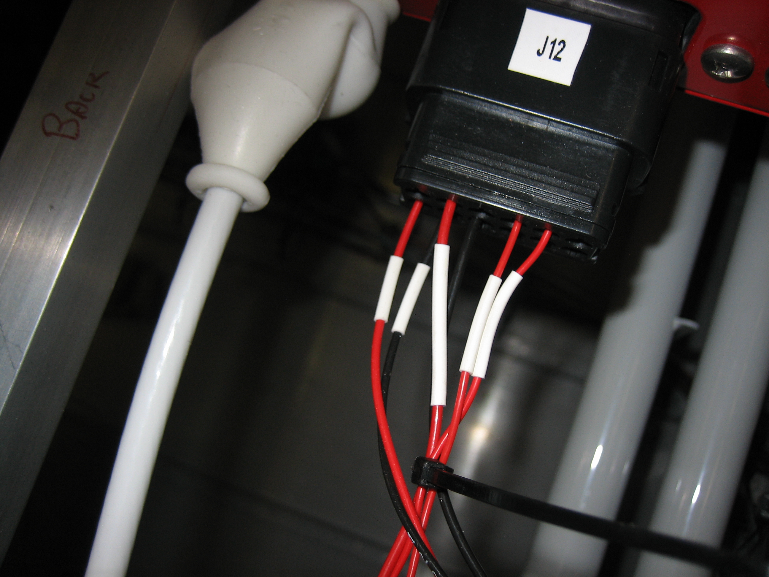
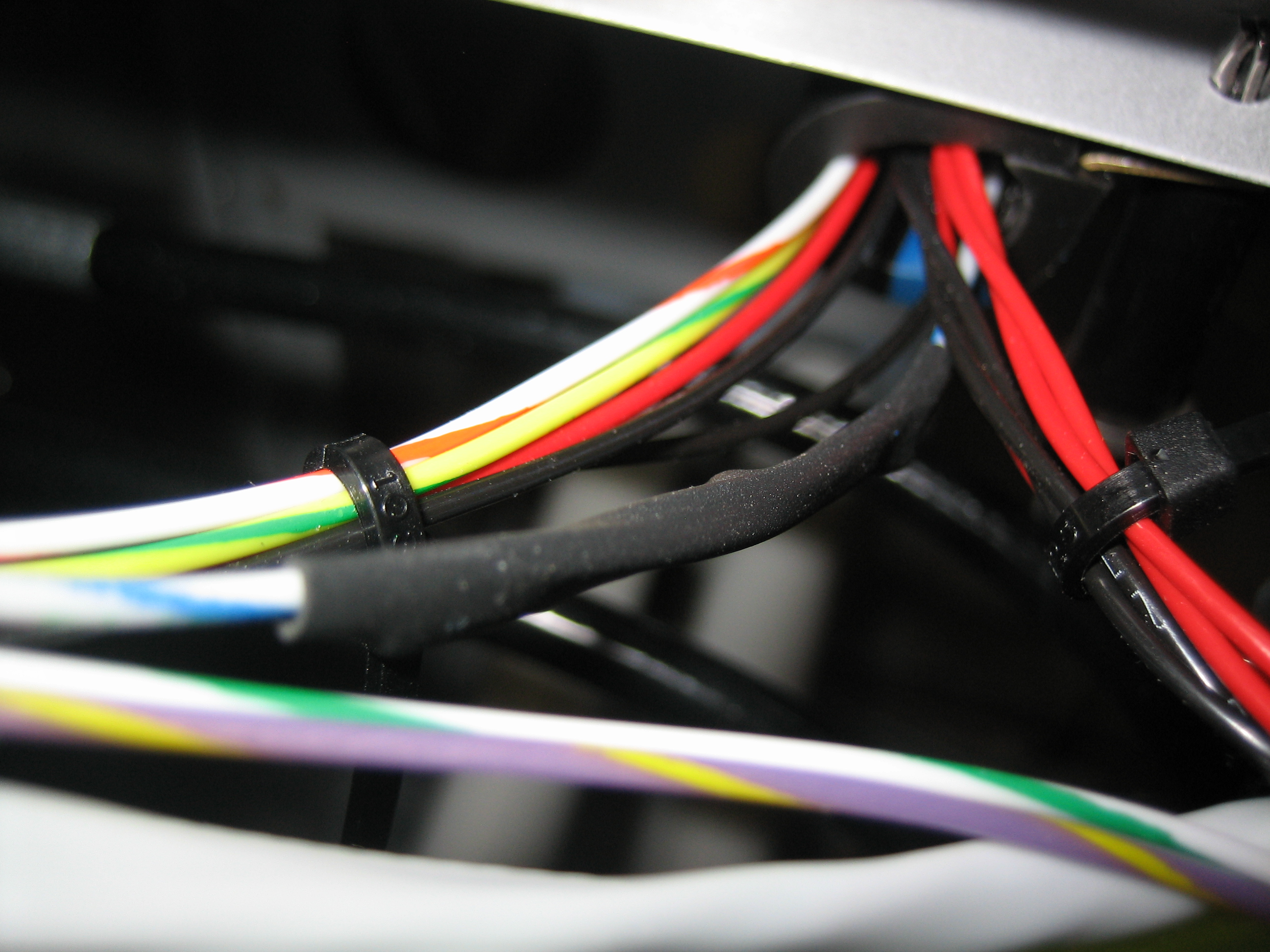
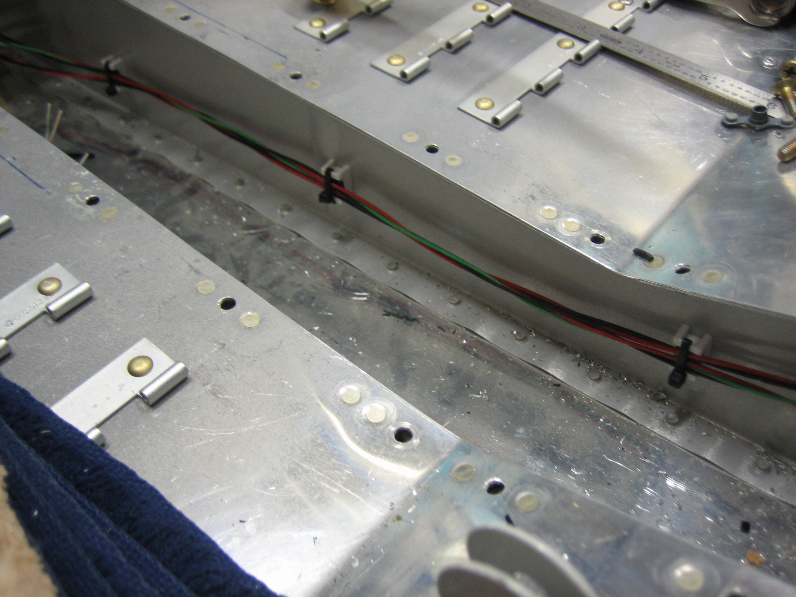
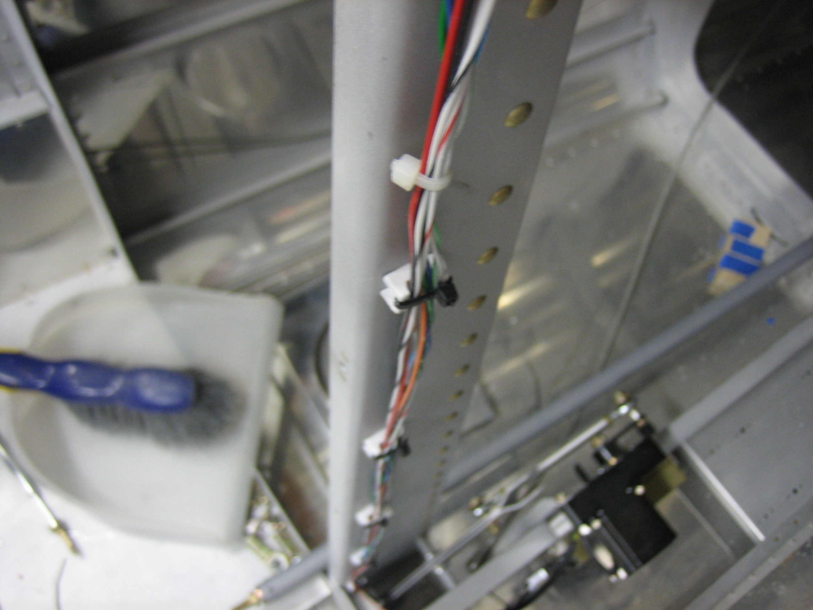
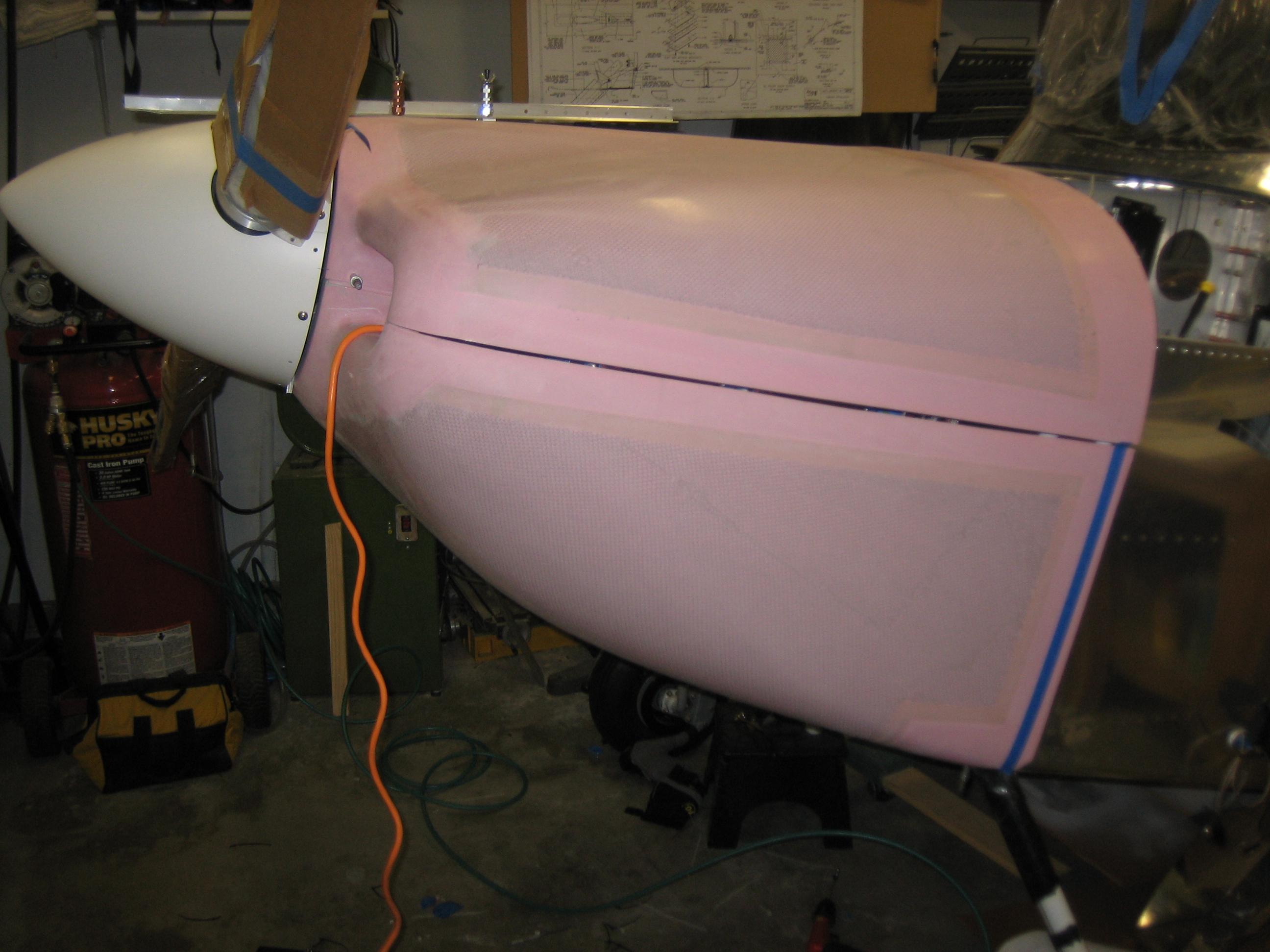
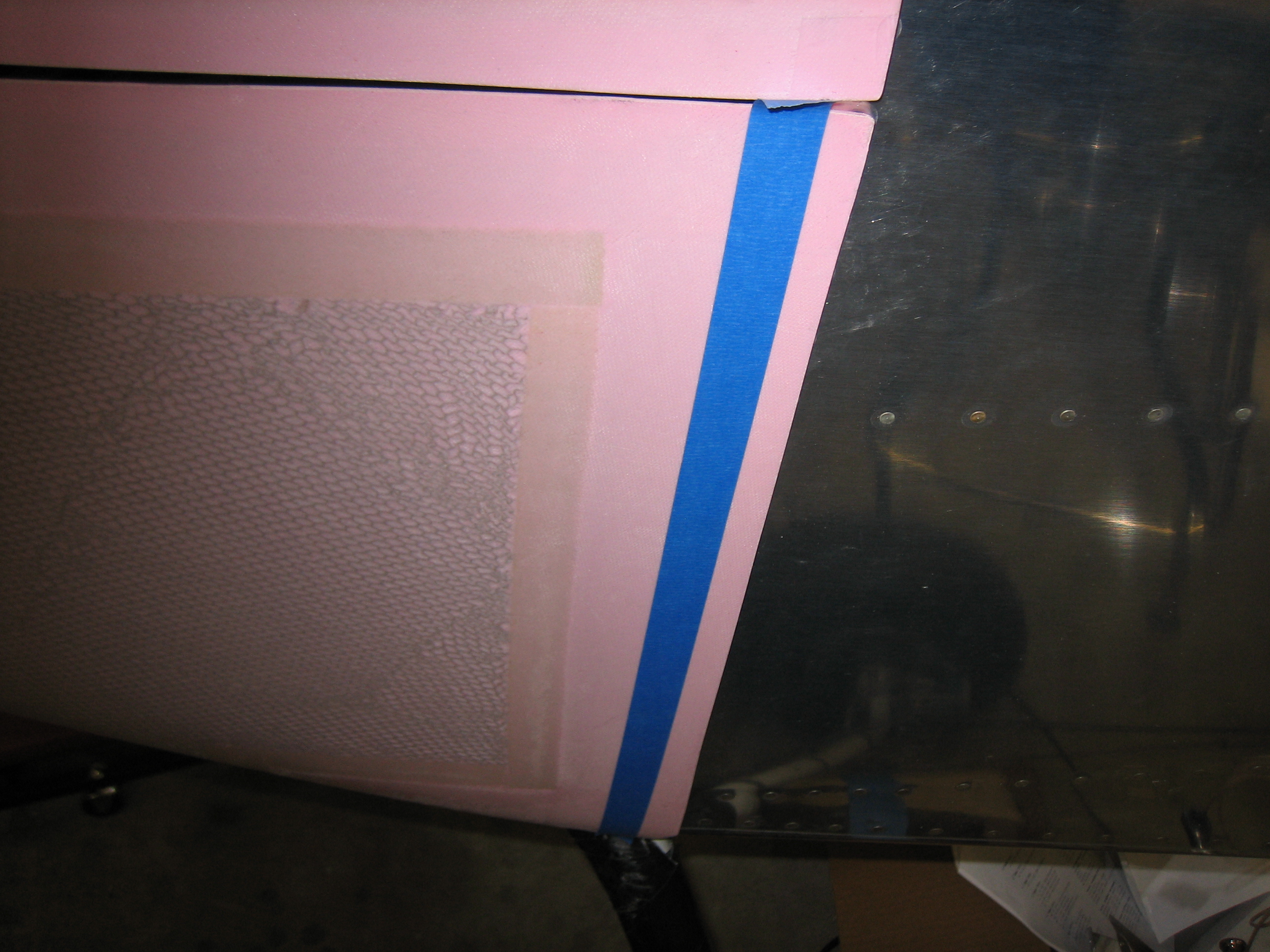
The cable to the fuel tank will get routed down the vent line, but I’m leaving it loose for now until I nail down the overall routing.

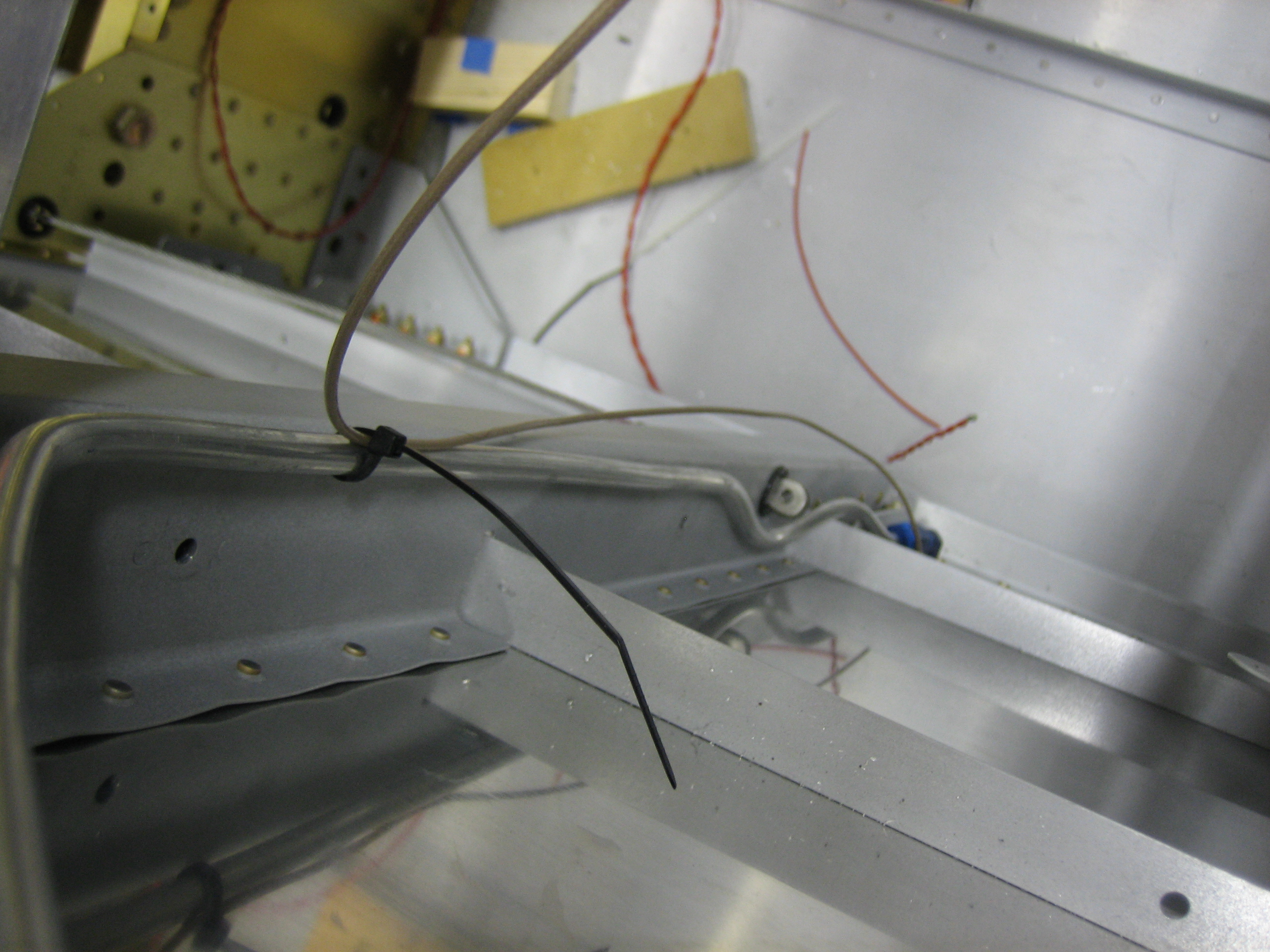
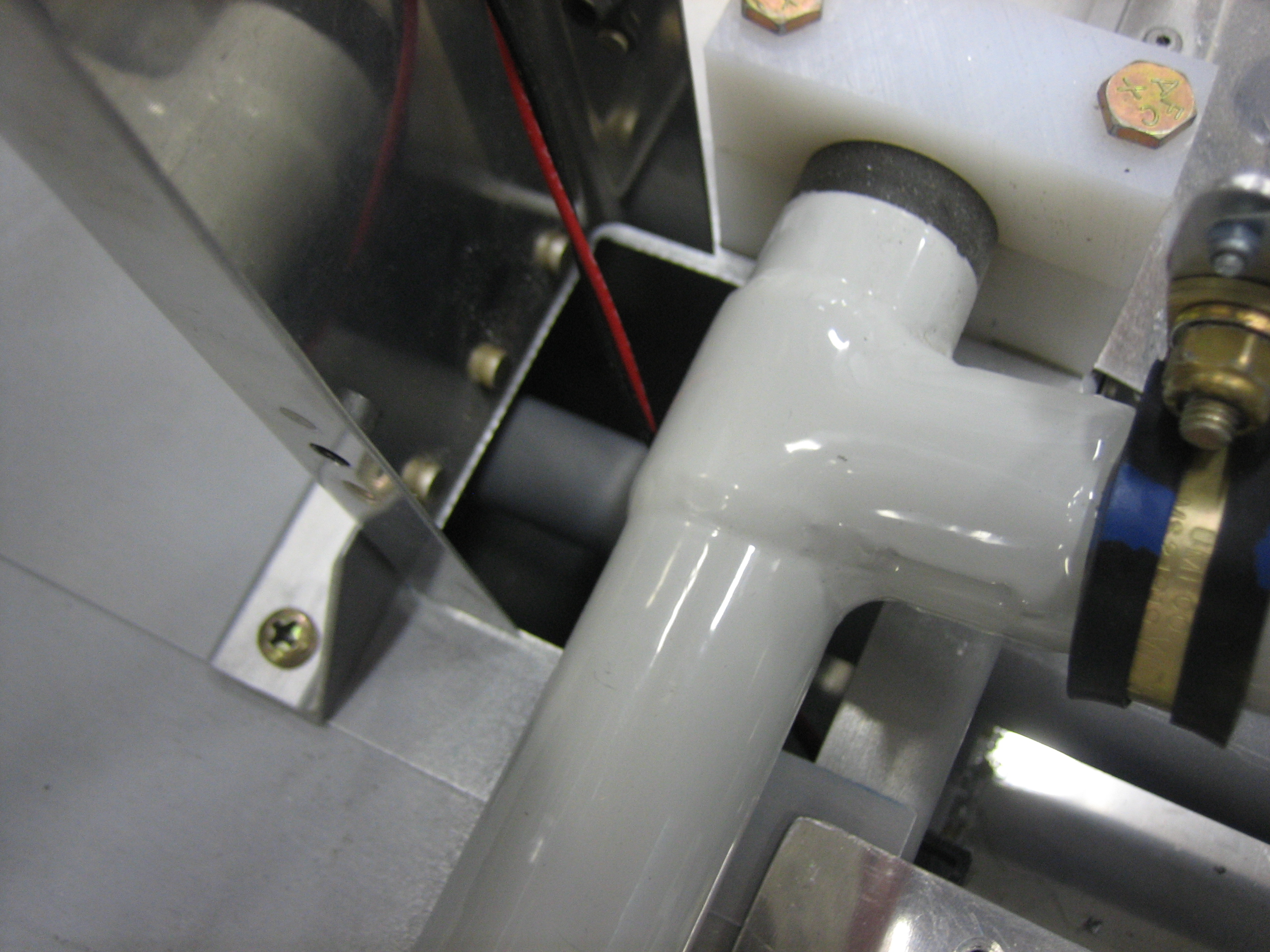
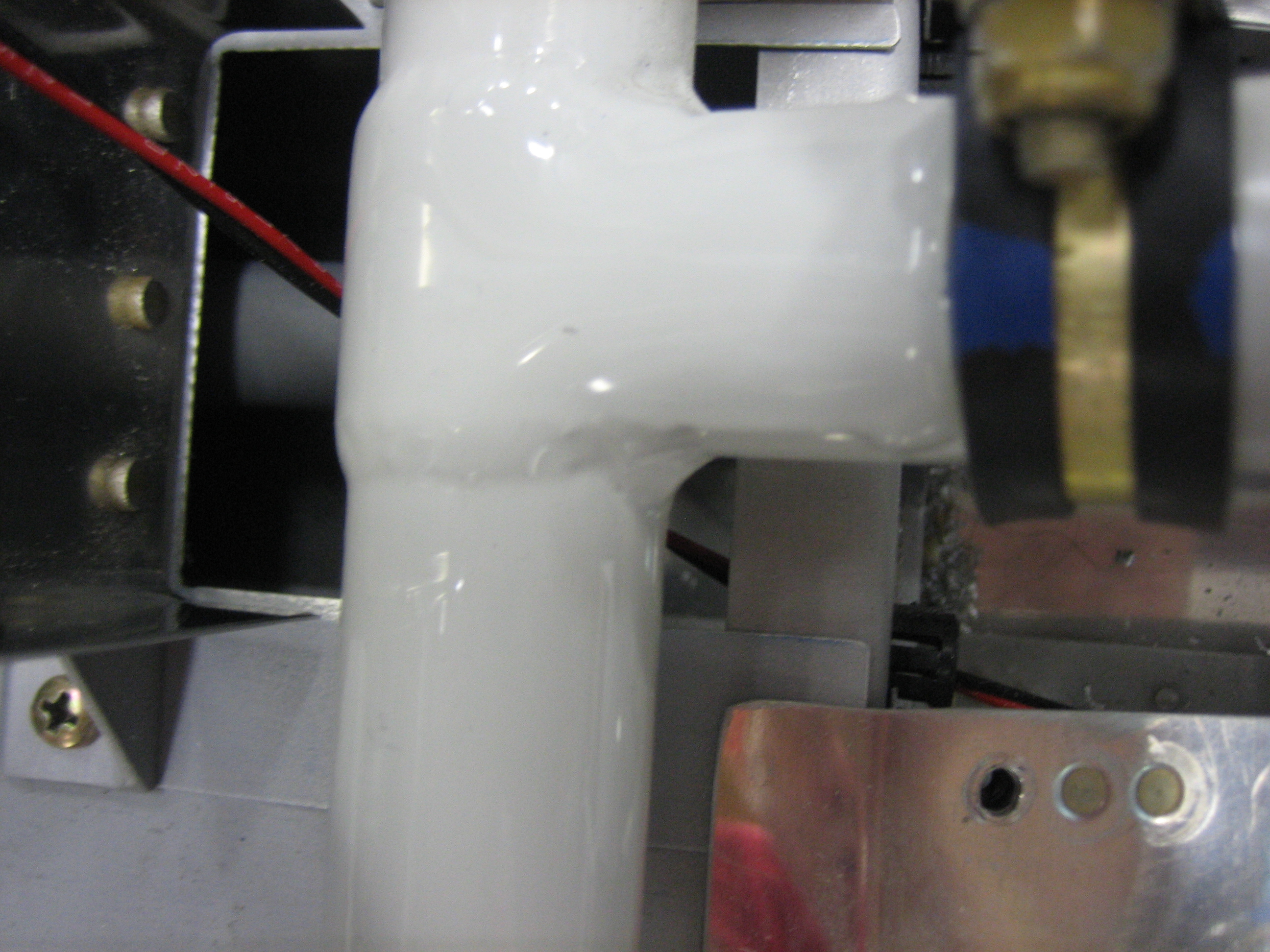
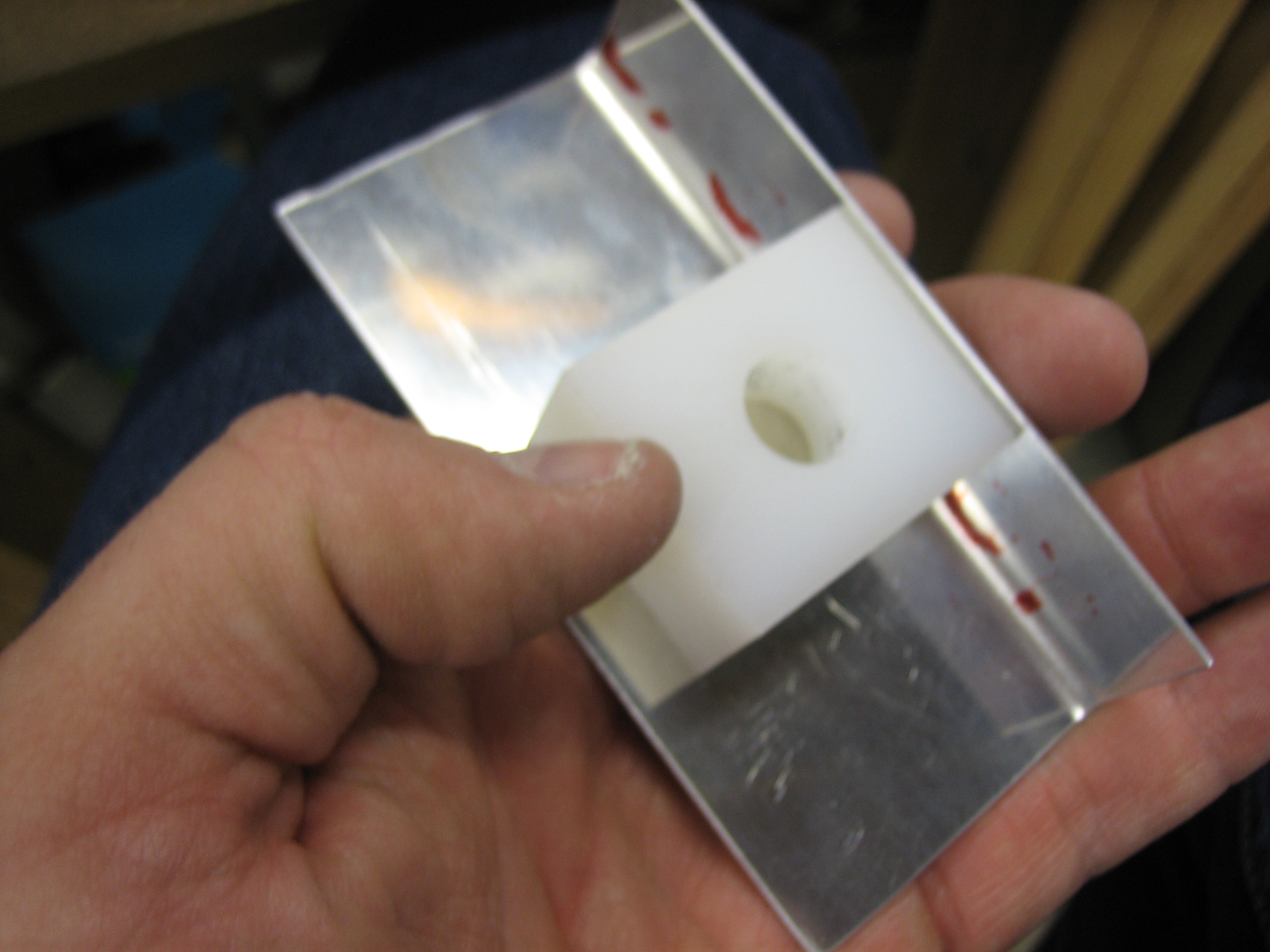
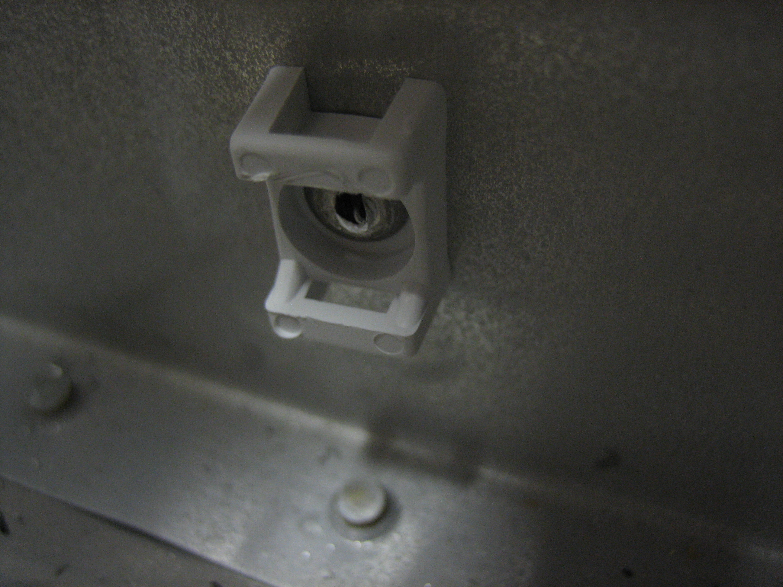
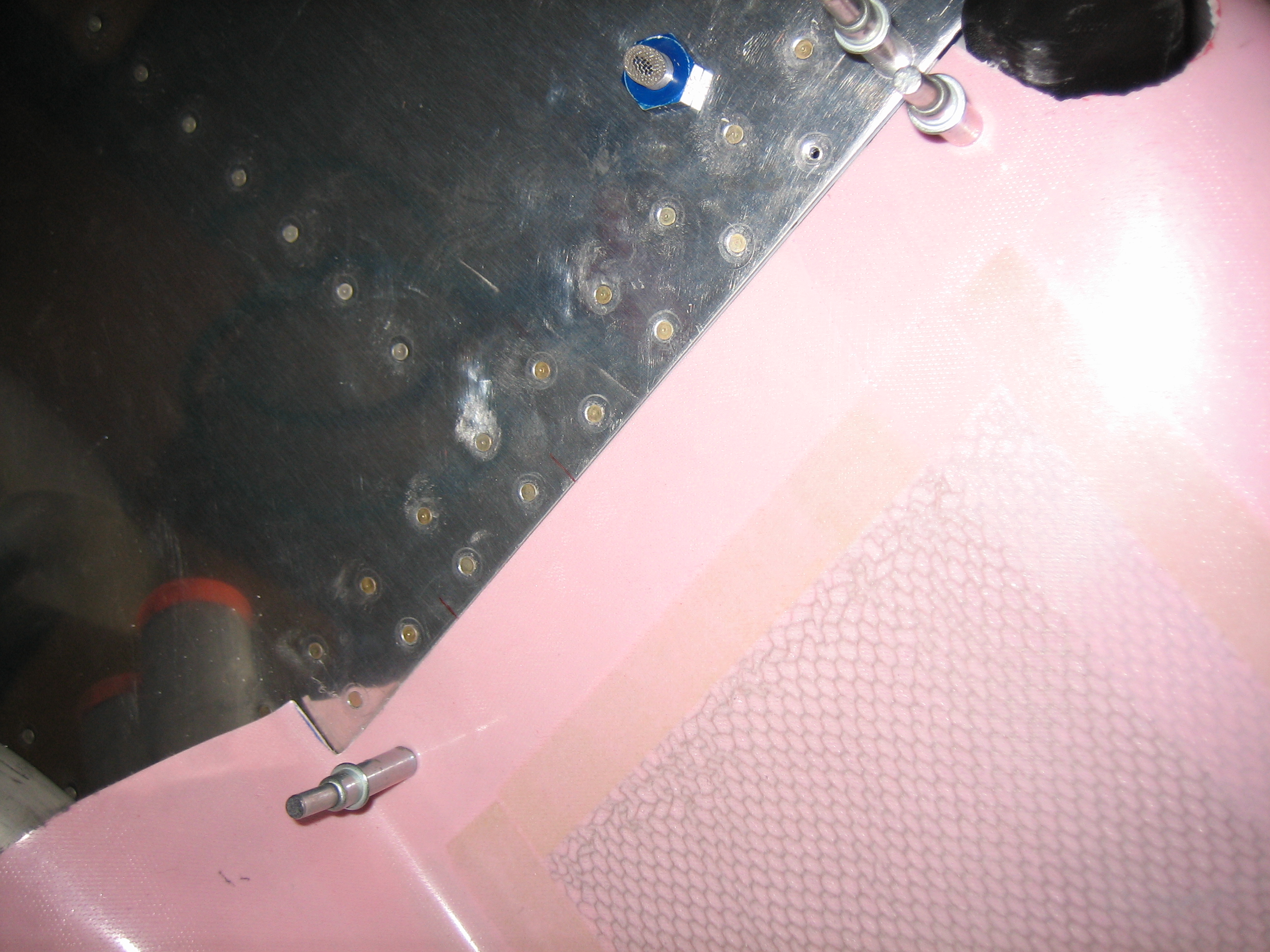
I drilled 1/4″ holes just above the vent bulkhead fitting and ran the cable with the BNC connector out through it.  This will get connected to the BNC fitting on the fuel tank which is wired up to the capacitive plates inside the tank.

Wired Up Fuel Senders and Finished EMS Wiring

I finished up the fuel sender wiring by running some wires from the other side of the molex connector.  The red and black wires go to power (VP-X) and ground respectively.  The striped wire is the included wire from the EMS running directly from the necessary pin.

I’m using a single pin on the VP-X (J8 connector) to power both senders.  The wire comes out of the connector and through the adel clamp on the right.  I then used a solder sleeve to split this wire into two: one that runs directly forward to the left fuel sender and one that goes through the left adel clamp and across the plane to the right fuel sender.

I grounded the two fuel senders as well as both SkyView screens (the two twisted pairs of the wires).  I’m down to 11 available spots on my grounding block which seems pretty tight.

I was down to just a handful of unconnected wires on the EMS, so I decided to finish that off tonight.  Two of the wires ran to the fuel senders.  One more ran over to the annunciator control circuit (not connected yet).  Another ran forward and will connect to the left ignition switch to get an RPM reading from the magneto.  Finally, I hooked up the low voltage RPM pins to the Lightspeed Ignition to get a second RPM source.

Here’s a closeup of the Lightspeed Tach line coming into the DB-37 connector.  It’s a shielded 22AWG wire.  I split the shielding out and put heat shrink over it and the split point and wired the center conductor to pin 35 and the shield to pin 16.

Cabin Lights and SkyView Wiring

I received some interior lights from pilotlights.net.  They were great to work with and even through in a couple of small bonus products with my order.  I’m trying to use all dual color (white/green) interior lights.  From the research I’ve done, everyone is moving away from the old standard of red for cockpit lighting at night.  Although it did fine at preserving your night vision, it makes reading maps really hard.  The military has moved to green, but research has shown that a really dim white light is actually best for preserving night vision while still giving you the best visual clarity.

Here’s the LED light strip I’m going to use under the glareshield (this is the 12V, high-power, dual-color white/green strip).  This is with just the white LEDs illuminated at full power.  It’s hard to capture with a camera, but this is definitely more light than you’d need in a cockpit.

Here it is with just the green LEDs illuminated.

And here it is with both (although I’m not going to wire it in the plane with the ability to light both colors at the same time).

Using one of the PWM dimmers (also from pilotlights.net), you can dim the light down pretty far, but not quite far enough.  A dropping resistor of 150? or so makes the range just about perfect.  You can dim almost down to off and the brightest setting is still plenty bright.

Here’s the PWM dimmer I’m using.  I bought three of these to replace the ones I purchased from periheliondesign.com.  The more I played with those, the less I liked them.  The lights flickered as you ramped up and down through the brightness range and putting the resistors to cap the low and high voltages wouldn’t expand the range of the dimming knob which means you would have to turn the knob a bit before it would come off the low dim setting and you’d hit the bright setting long before hitting the upper end of the knob’s range.  These PWM dimmers ramp smoothly across the whole range of the knob.  They also come with a much nicer machined aluminum knob instead of the plastic one on the dimmer from periheliondesign.com.

I also picked up this little four LED white light.  I’m going to put a dropping resistor on this and use it to cast a very dim light in the footwell.

I also went ahead and hooked up the four SkyView power wires to various pins on J10 and J12.  Each SkyView has one power wire going to bank A and one going to bank B for redundancy.

Wired Flap Position Sensor

I’m working quite a lot of hours at work now, so I’m not getting much time on the plane, but I want to make some progress on the plane every day that I can.  Since I got the flaps wired up last night, I decided to wire up the flap position sensor tonight.  These will be the last wires that need to run down the center tunnel.  I installed a three position molex connector for the position sensor.  I’m still not sure how I’m going to anchor these to the rear cover.

I didn’t want the wires from the position sensor to rub the screws that attach the side covers to the flap housing, so I used a small drop of E6000 to secure the wires to the side of the position sensor.

I also swapped out the four position molex connectors on the fuel senders for three position connectors.

I attached the two flap wires to J12, pins 5 and 6 (the lower left red and black wires).

And the three flap position sensor wires to J1, pins 17, 18, and 19.

Wired Flap Motor

I ran the wires to the flap motor tonight.  I put a two position molex connector on the wires so that the motor can be easily disconnected if it needs to come out.  There will also be a second connector here for the three pins from the flap position sensor.

I cut away a chunk of the forward end of the aft tunnel cover (basically the part that will be inside the flap motor housing.

This lets the wire that runs down the flap tunnel pass through the rear spar before coming up behind the flap weldment.  All of this will be secured by some wire tie mounts to keep it from coming in contact with the weldment.

Installed Starter Annunciator Input to VP-X

I spent most of the day working, but I had a little time so I snuck out to the garage for a bit. I cleaned up some of the wire runs and installed the wire from the starter contactor to the VP-X so that I’ll get a “starter engaged” annunciation on the EFIS.

I put a 1kΩ resistor inline with the wire.  Unfortunately, I didn’t see the note that this was to protect the wire and should be close to the contactor, so I’ll have to replace this wire.

Started Aileron Trim

I replaced the wire from the starter contactor to the VP-X so that I can add protection for the wire close to the contactor.

I also got an order from Aircraft Spruce with a replacement cabin/baggage light.  The one I had had both red and white lights, but as I mentioned earlier, I’m using all white and green interior lights, so I ordered this unit.  I wish this was offered in a natural aluminum anodized finish since this will be the only black anodized aluminum in the cockpit, but it’s not that big of a deal.

Afterward, I decided to get started on the aileron trim.  First up is to fit the bushing block into the bracket.

I radiused the corner so that it nestles tight into the bracket.

Next, I used the sanding drum on my Dremel to notch the bushing so that a cotter pin can be inserted through the shaft.

I drilled various holes in the bracket on the right so that it can be installed between the seat ribs.  I also cut down the shaft of the bracket so that it sits below the surface of the bushing.  This is because the open end of the shaft shown here sits up against the bottom of the bracket on the right.

Mounted Aileron Trim

I drilled the bracket shaft with a #53 bit and installed the cotter pin.  This is a snug fit, so there is zero slop in the bracket.

Here’s the whole mechanism assembled.  The servo pushes on the bracket and will turn it around the shaft.  Spring linkages will connect the other bracket arm to the control sticks to bias the neutral point.

Here’s a closeup of the linkage between the servo and the bracket.

The bushing block is bolted to the mounting flange with one #10 screw and one AN3 bolt through the holes I drilled yesterday.

The hole for the #10 screw was dimpled in the mounting flange and the bushing was countersunk since the seat pan gets installed right above this and there wouldn’t be clearance for a bolt head.  The other hole can just use a normal bolt since there are no space considerations.

Finally, I mounted the bracket between the seat ribs.  I had to remove the elevator pushrod to get the angle drill in here to drill the servo to the skin.

Installed Cable Clamps and Aileron Trim Connector

I got an order from Avery Tools today with some cable clamps that can be attached with screws or pop rivets.  I’m using these in lieu of the adhesive cable clamps in areas where the detachment of the clamp could interfere with the controls.  I’ll likely end up installing these in any spot where it’s fine to drill a hole through the structure.  I really wish I knew about these back when I installed the conduit under the seats and baggage floors instead of the adhesive cable clamps.

I installed several of these along the forward center tunnel to keep the flap motor and flap position sensor wires away from the elevator pushrod.  Jeez, do I need to vacuum in here or what?

I also installed a set of these up the center baggage wall support to secure the network cable to the ADAHRS.

Finally, I slipped some sleeving over the wires to the aileron trim servo and installed a five position molex connector I picked up at Fry’s this morning.

Started Fabricating Vent Brackets and Worked on Cowl

I started fabricating one of the brackets that will be used to mount the air vents.  These are fabricated out of 0.063″ stock which is the same as the instrument panel.

Here’s how it fits in the plane.  You can see how it nestles nicely up against the instrument panel and the flange of the vent overlaps both.  I’ll cut off the lower right of the bracket at the small horizontal black line and let the bracket follow the curve of the vent around to the bottom.  I left the bracket a little tall on the left side for now since I had Classic Aero Designs fabricate the side panels to the original height of the vent brackets.  I don’t know if they’ve cut these parts yet, so I’ll see if they can still change them.  If so, I’ll cut this off straight.

I reinstalled the cowl so that I can continue the fitting.  I had previously put this on hold while Van’s evaluated whether the flanges on the cowl sides were cut too short but haven’t gotten back to it until now.

I had previously cut the aft edge of the bottom cowl to length, so I carefully lined up the cowl all around and drilled a couple of holes on each side to the stainless steel hinge to lock the bottom in position.

I put a work light inside the cowl and marked the approximate cut line on the sides.  It’s too late to run the cutoff wheel tonight, so this is a good place to stop.