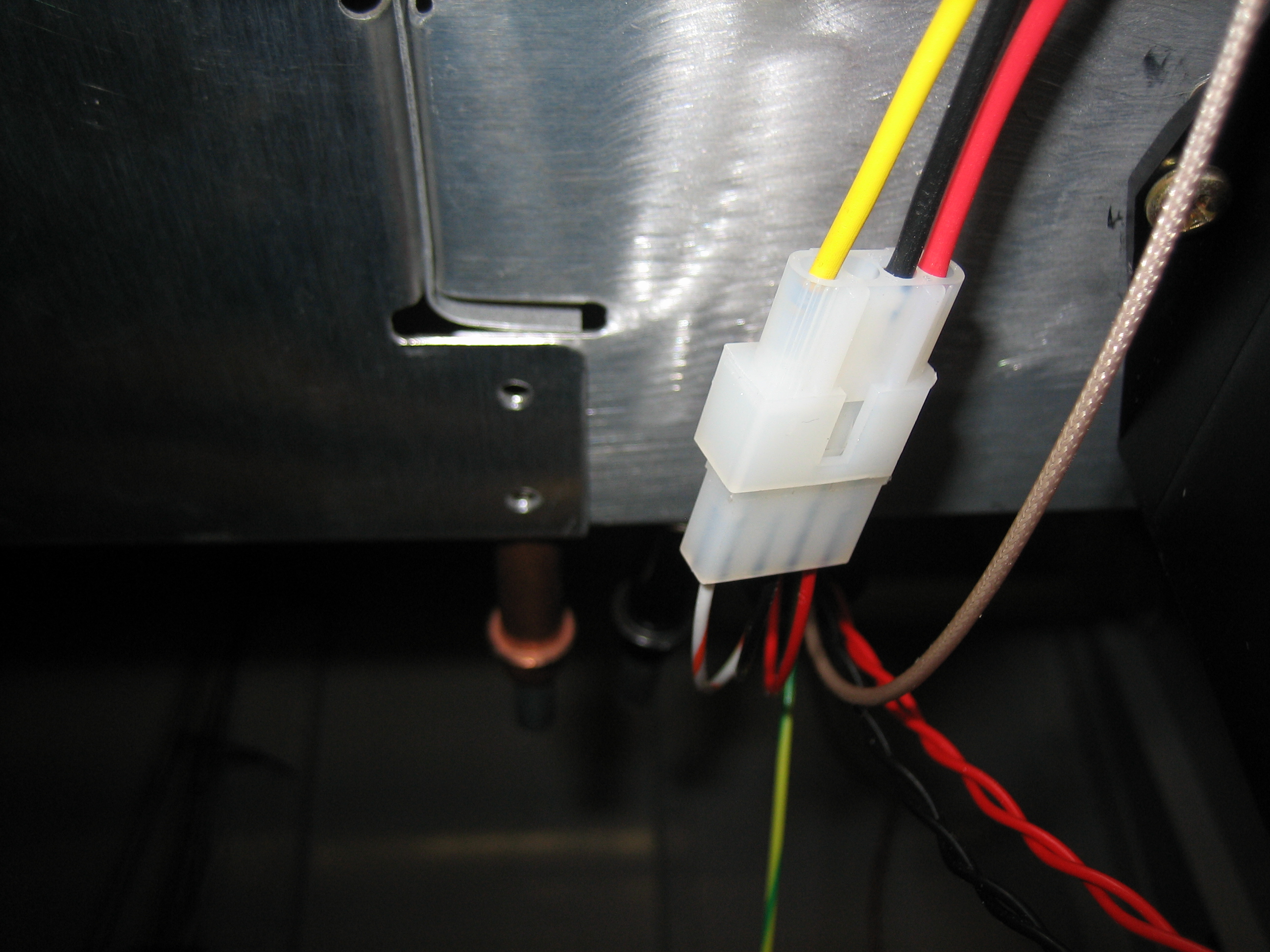
I finished up the fuel sender wiring by running some wires from the other side of the molex connector. The red and black wires go to power (VP-X) and ground respectively. The striped wire is the included wire from the EMS running directly from the necessary pin.
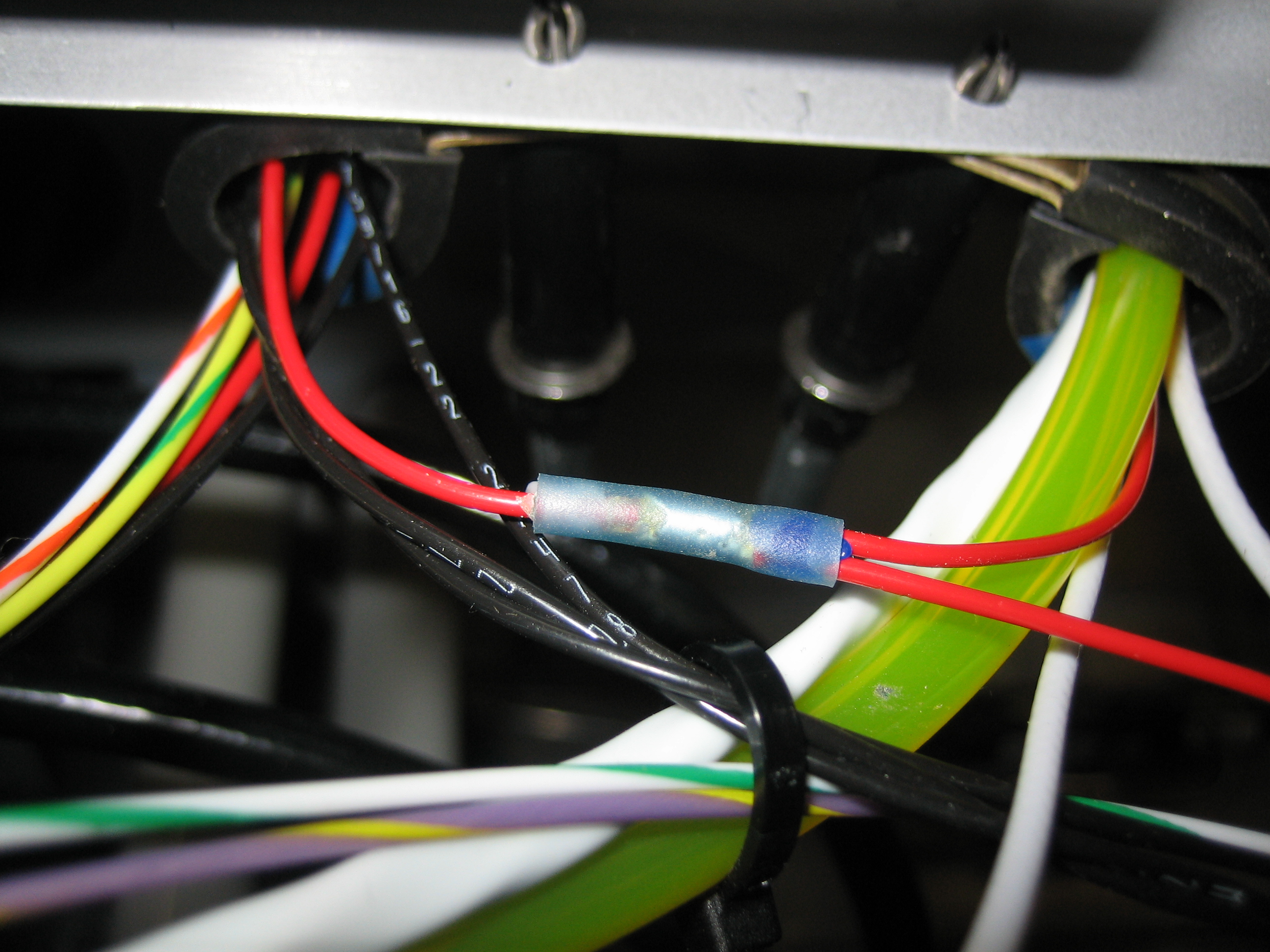
I’m using a single pin on the VP-X (J8 connector) to power both senders. The wire comes out of the connector and through the adel clamp on the right. I then used a solder sleeve to split this wire into two: one that runs directly forward to the left fuel sender and one that goes through the left adel clamp and across the plane to the right fuel sender.
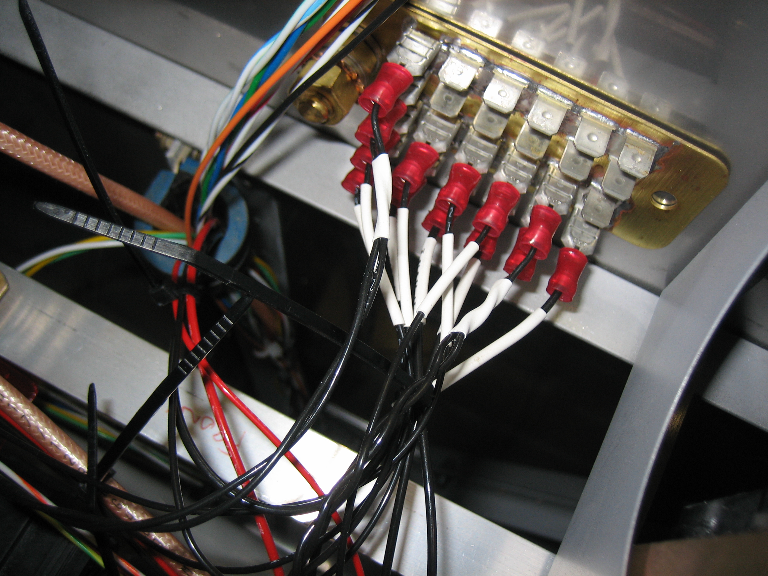
I grounded the two fuel senders as well as both SkyView screens (the two twisted pairs of the wires). I’m down to 11 available spots on my grounding block which seems pretty tight.
I was down to just a handful of unconnected wires on the EMS, so I decided to finish that off tonight. Two of the wires ran to the fuel senders. One more ran over to the annunciator control circuit (not connected yet). Another ran forward and will connect to the left ignition switch to get an RPM reading from the magneto. Finally, I hooked up the low voltage RPM pins to the Lightspeed Ignition to get a second RPM source.
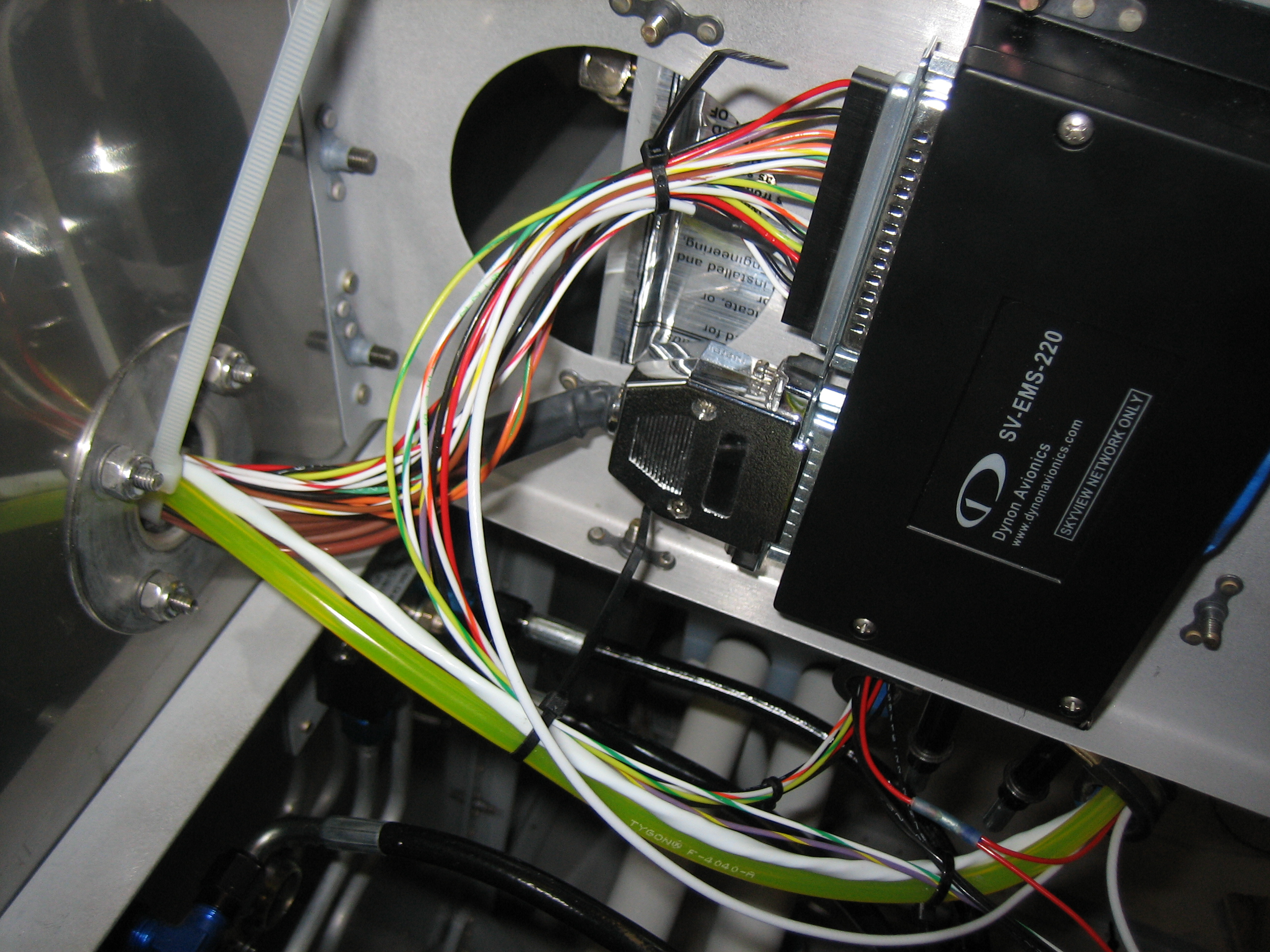
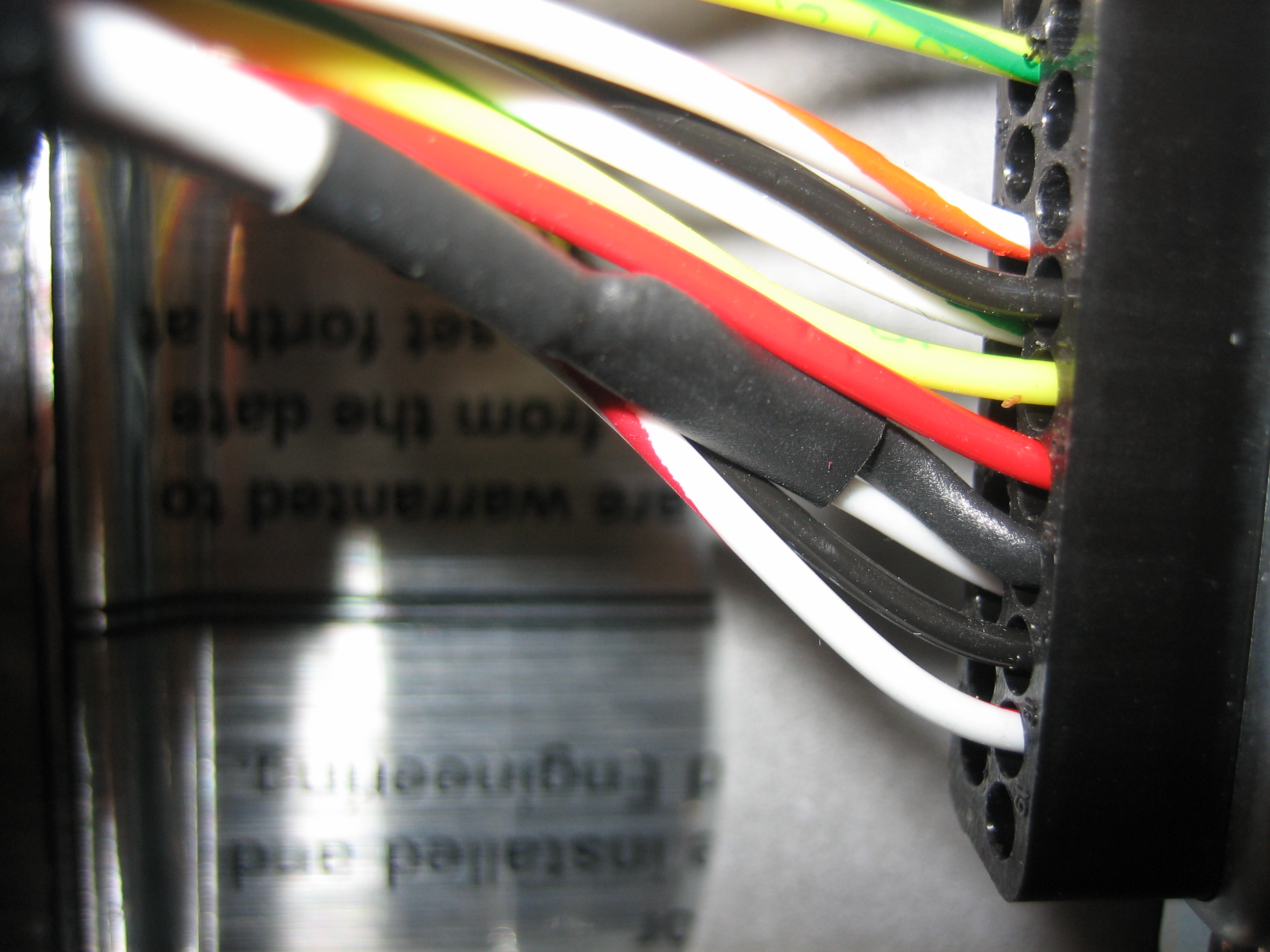
Here’s a closeup of the Lightspeed Tach line coming into the DB-37 connector. It’s a shielded 22AWG wire. I split the shielding out and put heat shrink over it and the split point and wired the center conductor to pin 35 and the shield to pin 16.