The RV-7 was designed before the days of composite constant-speed propellers, and was further designed for the 200hp, angle-valve IO-360 motor. Taking Van’s advice to build the lightest plane possible, I opted for the WhirlWind Aviation 200RV composite prop and the much lighter IO-375 motor. This meant I was approximately 70lbs lighter in the nose than the plane was designed for. This put my C.G. much farther aft than typical, and it was in fact easy to load the plane aft of the aft C.G. limit.
I spoke with Van for a bit at a party last year, and he indicated that the easiest change to make (short of just bolting on some weight) would be to switch to an aluminum constant speed propeller. When my 200RV prop started slinging grease back in the spring, it seemed like the perfect time to do the swap.
I ordered the Hartzell C2YR-1BFP/F7497 through Van’s. This is a 74″ prop and not normally recommended for the RV-7 due to being 2″ longer than the 72″, recommended prop. However, I spoke with someone at Hartzell, and he indicated that there were advantages in thrust with the 74″, and the extra weight only helped my situation. The only downside for me is reduced ground clearance. The 200RV had 8 3/8″ under normal gear compression in a level attitude, so this prop should have 1″ less, or 7 3/8″. In a hard landing, or if I inadvertently raised the tail too far, this would be reduced. However, I virtually always fly off hard surface runways and generally do tail-low wheel landings, so I’m not particularly worried about the reduced clearance.
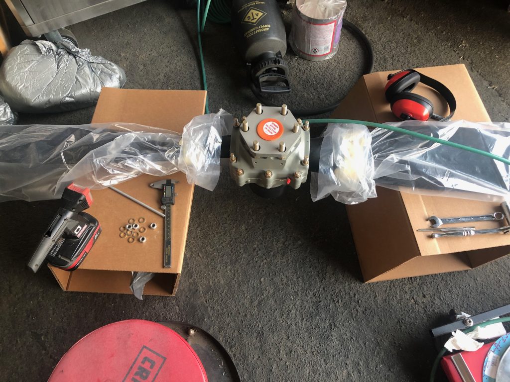
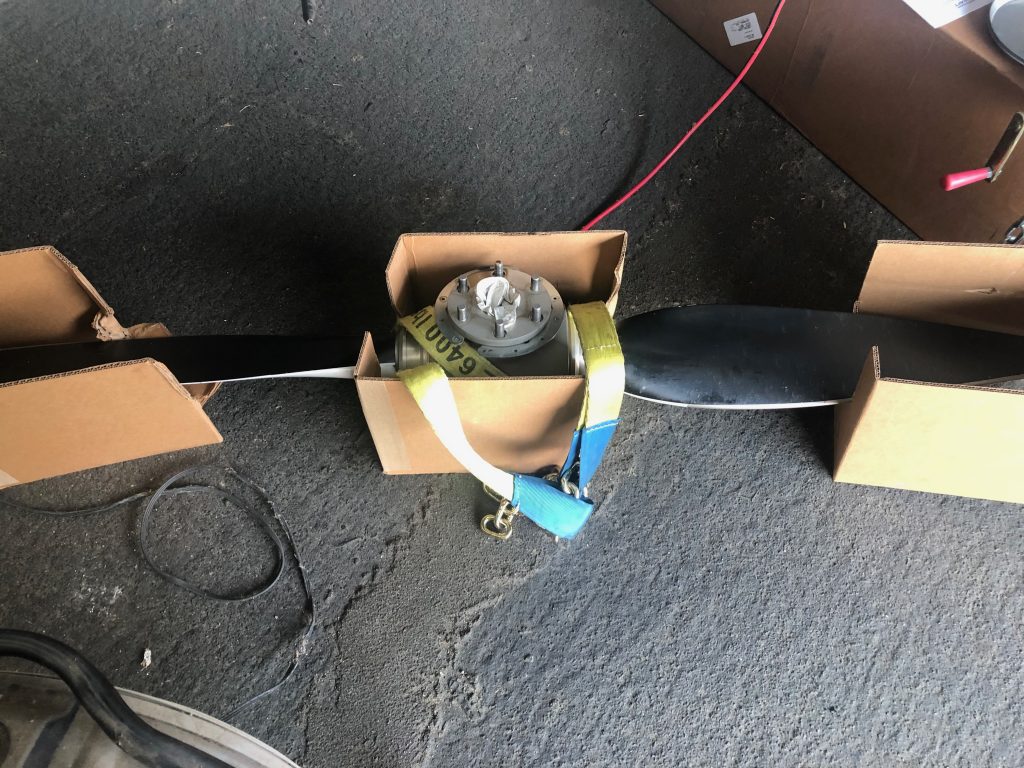
The prop shipped 4-6 weeks later and pretty quickly landed at the UPS hub in San Jose, CA where I live. Unfortunately, UPS then lost track of it for three weeks! Eventually, it turned up in a trailer full of packages that apparently sat unopened that whole time. I dropped by their hub and picked it up and brought it to the hangar where I opened it and got it ready to mount on the plane.
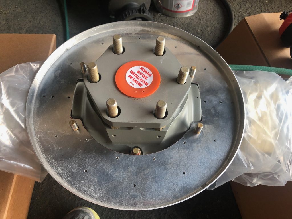
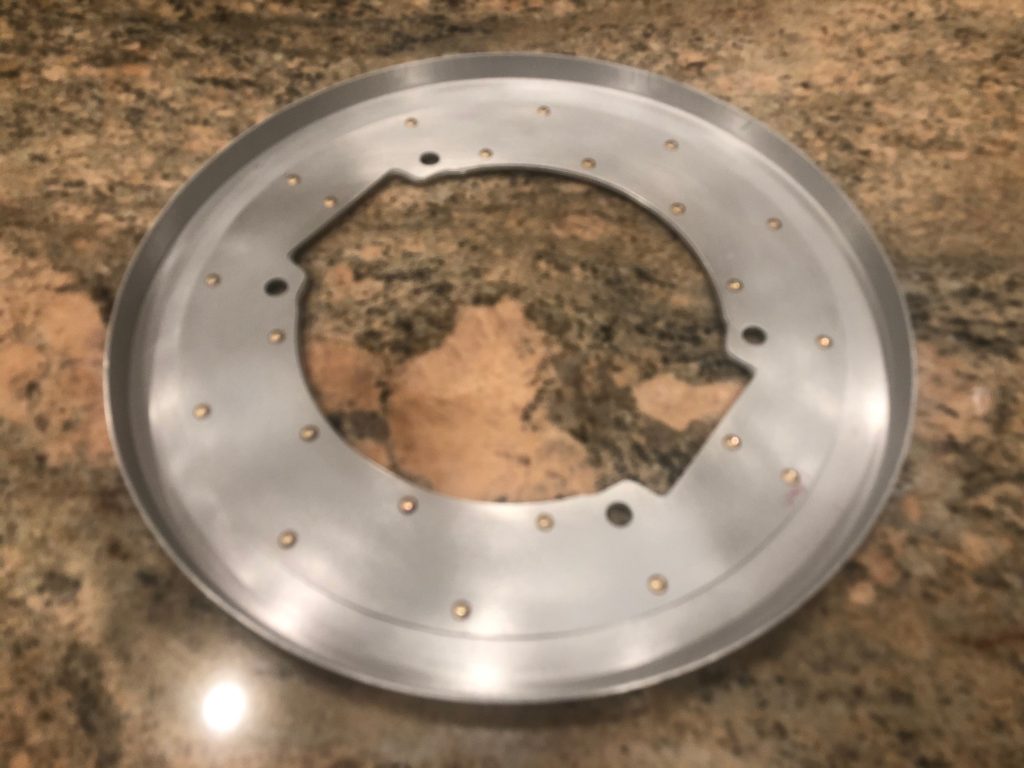
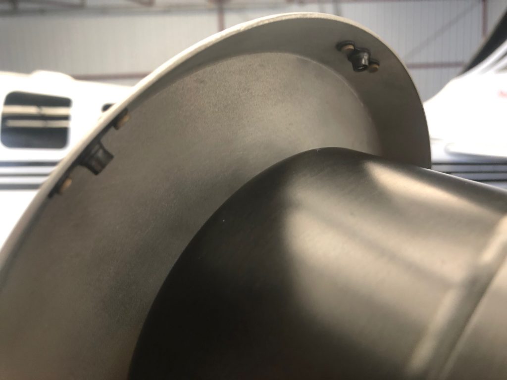
The first step is fitting the rear spinner bulkhead. This needs to be cut to match the doubler and then relieved further to fit on the propeller without touching the hub itself.
My buddy Michael was kind enough to let me drop by his place and shoot some of the Stewart Systems primer on the front and rear bulkheads, then I riveted the two parts of the rear bulkhead together.
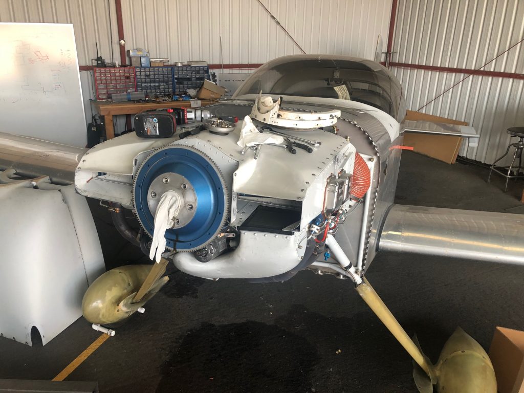
When everything was ready with the new prop, I pulled the old prop from the plane.
I’ve had some back pain recently, so I used this lifting sling with my shop crane to get the old prop off and install the new prop on the plane. This was far easier that trying to hold the prop with one arm while manipulating the bolts with my other hand.
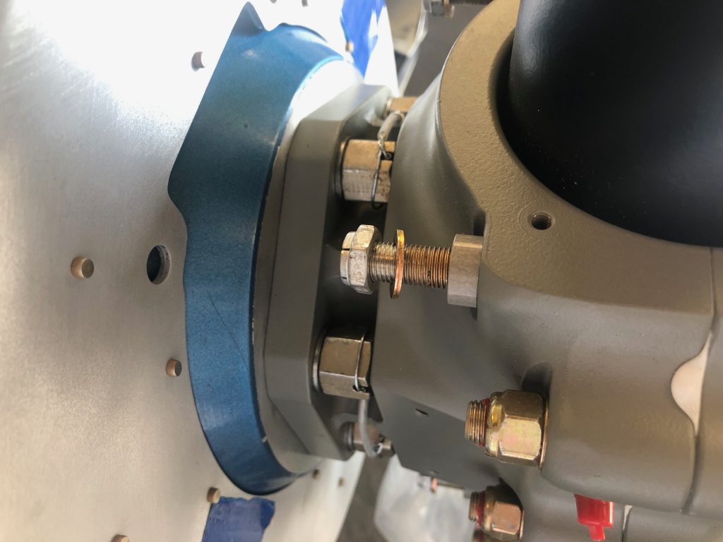
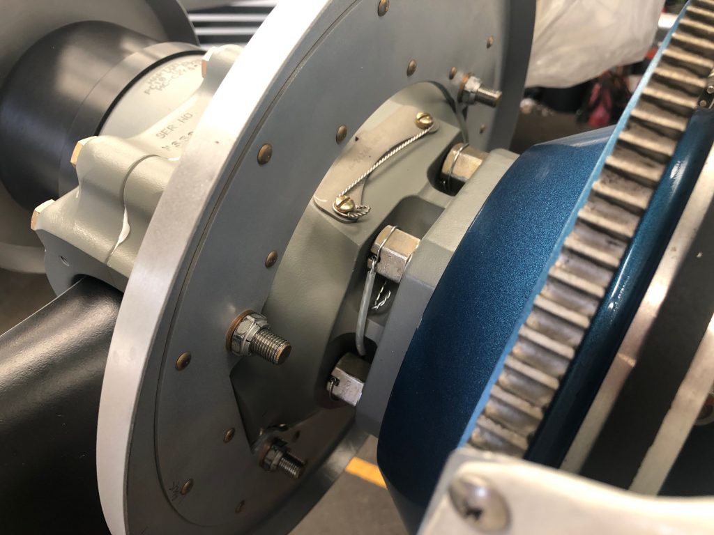
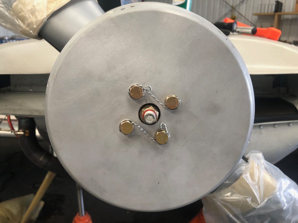
I taped the new bulkhead to the flywheel while installing and safety wiring the new propeller.
I then installed the rear bullhead to the hub retaining bolts and torqued them to spec.
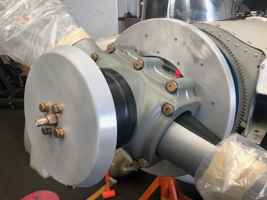
I temporarily installed the front bulkhead so that I could begin fitting the spinner.
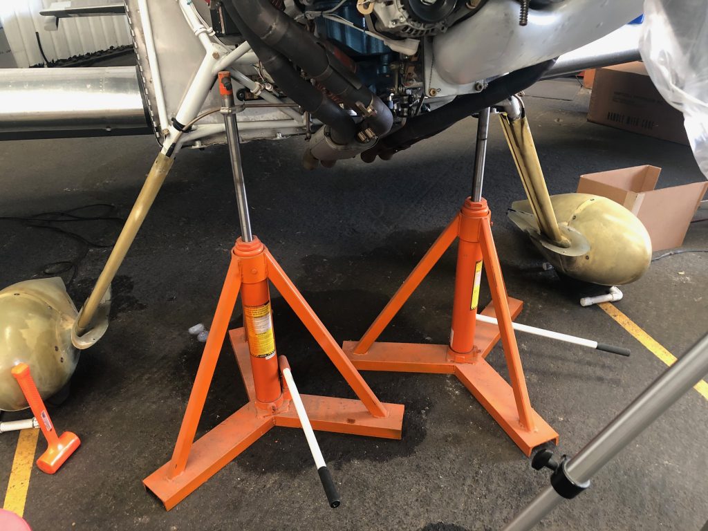
I needed to be able to turn the engine freely when fitting the propeller, but I needed it to be fairly stable. I used the same technique I did when fitting the wheel pants, and jacked the plane up by the engine mount. I then removed the lower spark plugs so that the engine could spin freely.
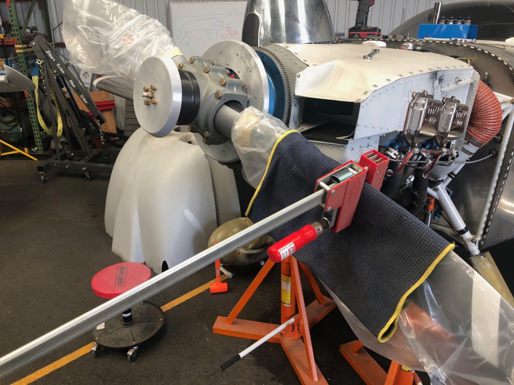
When fitting the spinner, I also needed to be able to cycle the blade from the fine pitch stop to the coarse pitch stop. I ended up using some padding and one of my Bessey clamps which worked perfectly. Here is the propeller at the fine pitch stop.
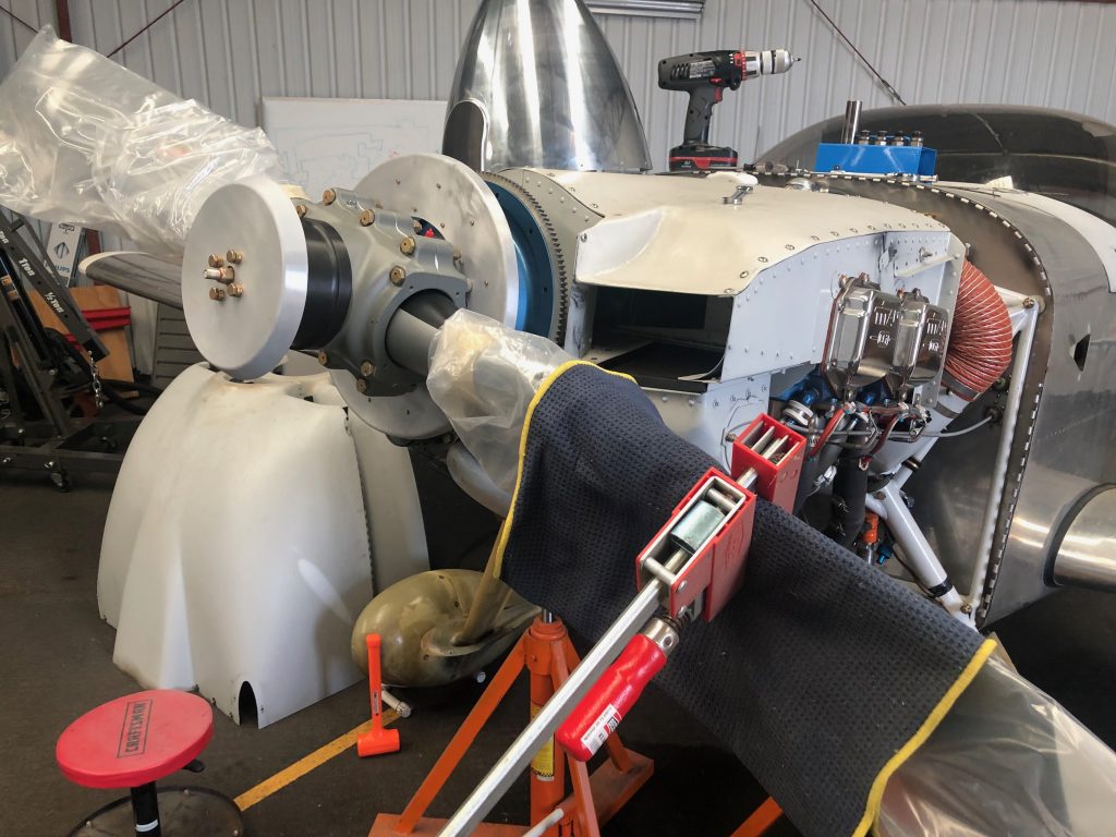
By just pushing down on the clamp (and holding the propeller tip to prevent it from rotating the engine), it was easy to twist the blade to the coarse pitch stop.
I’m using the Cummins Spinners spinner for this propeller. I emailed Alan back in the spring to inquire about purchasing one of these, but there was no response. Others online said that hadn’t been able to get ahold of him for over a year and a half! I gave up hope and ordered the spinner kit from Van’s, but just before install, I received an email out of the blue from Alan saying he had a spinner ready to ship! It took a couple of weeks to get here from Australia, but it’s worth it for the look of a polished spinner on the plane.
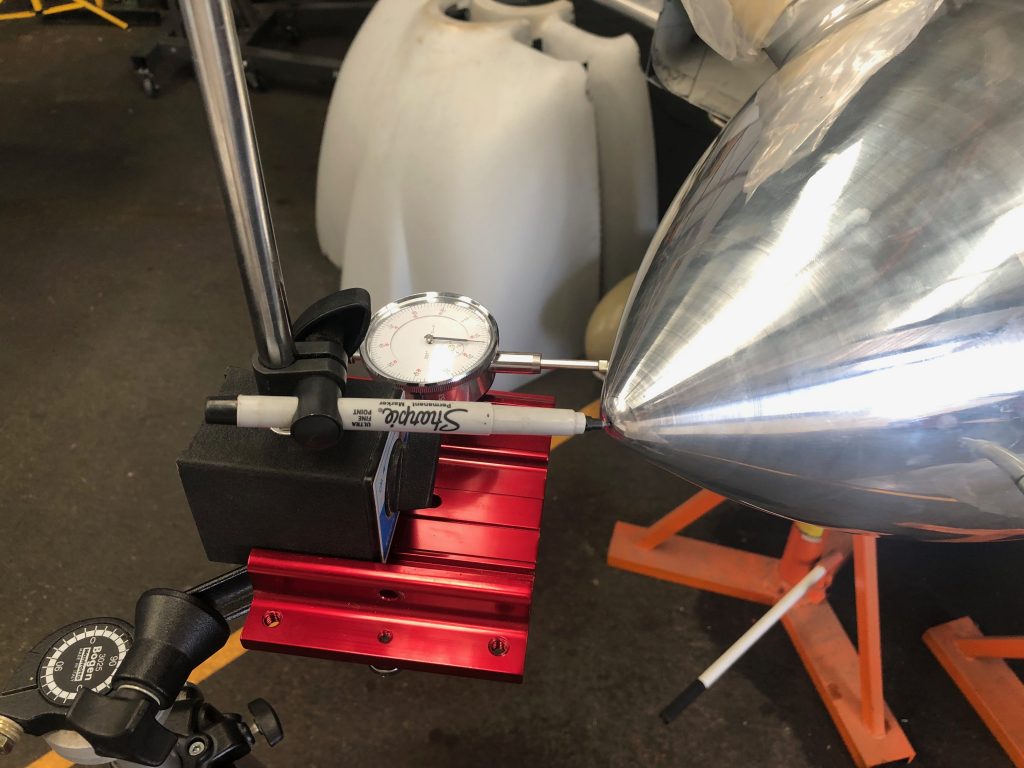
To ensure the spinner was centered, I used a combination of a marker at the tip and a dial indicator on the side to measure wobble. I think it’s impossible to get this to 0″, but I feel like I got pretty close. You couldn’t see any deviation with the marker tip and the dial indicator showed +/- 0.003″ deviation. Since the spinner is 0.065″ aluminum, that’s only about 5% of the thickness of the spinner!
After drilling all of the holes, I set the nut plates on the front bulkhead.
…then safety wired it in place.
My buddy Greg found a metal polishing place about 45 minutes from my house, so I dropped the spinner off and had them polish it to a mirror finish.
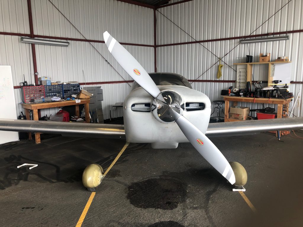
Interestingly, the prop clocks at a different location when the engine’s stopped. The old prop would be level after shutdown.
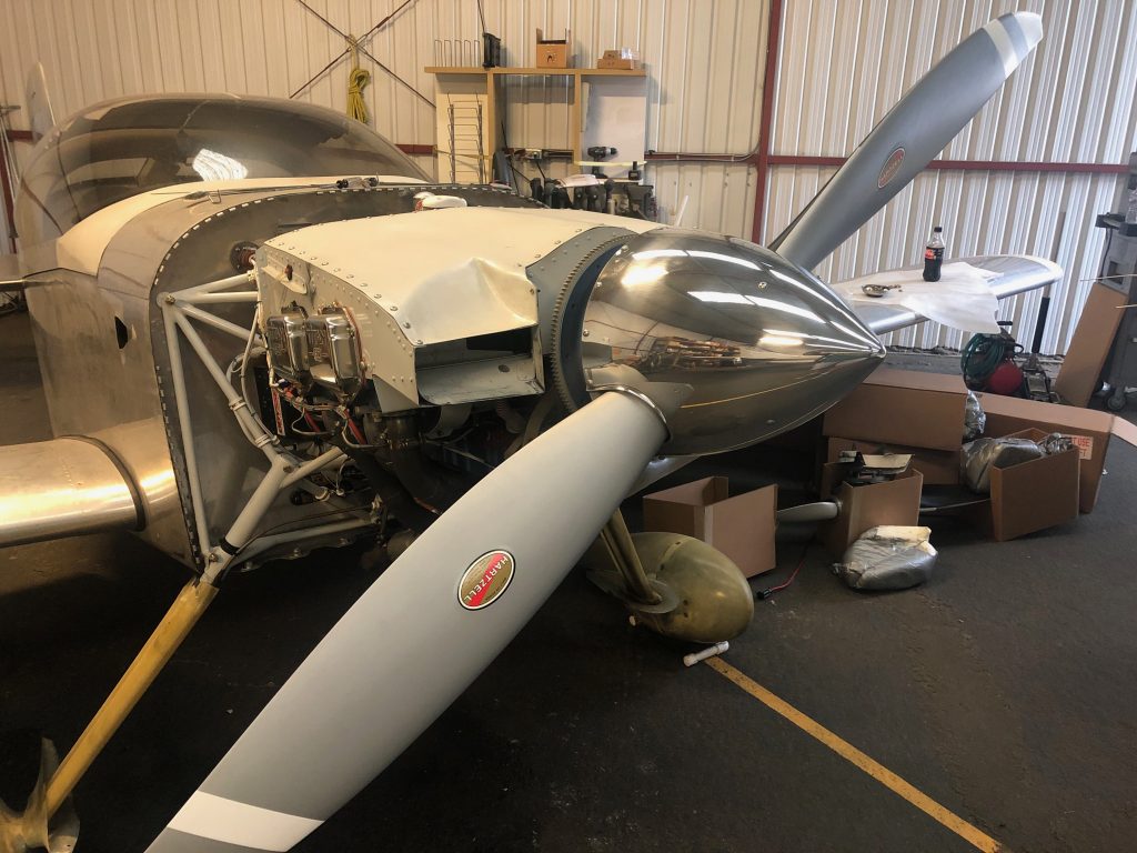
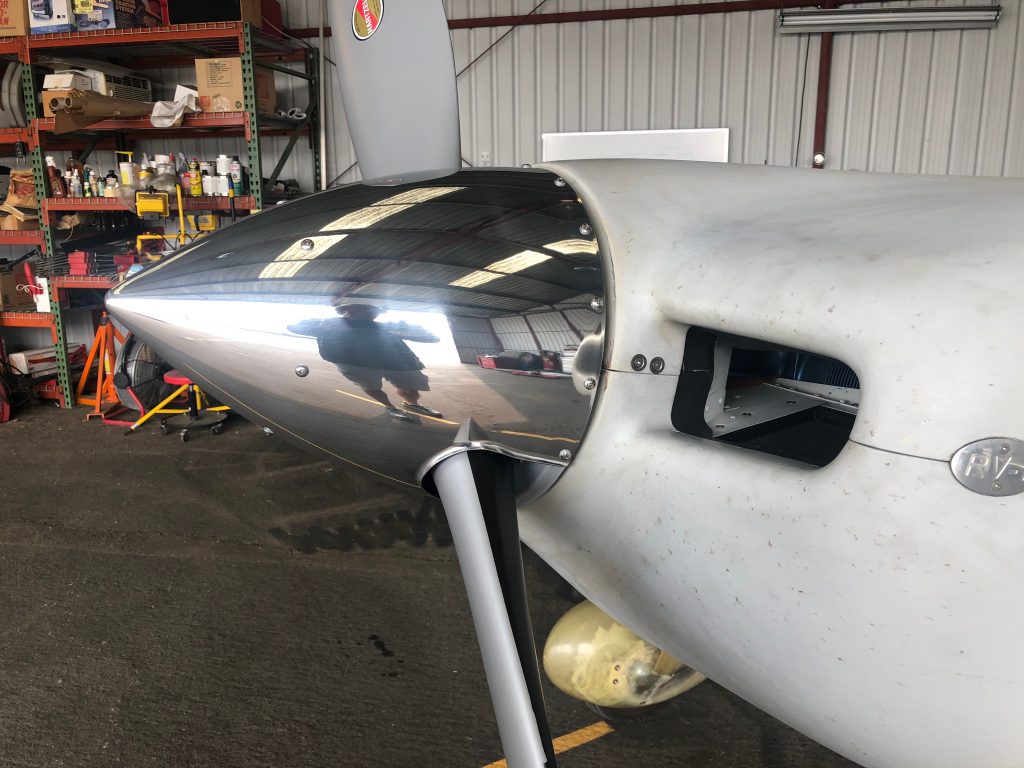
It looks like I’m going to need to raise the prop a small amount due to engine mount sag. You can see the misalignment of the spinner and cowling clearly here. The spinner sure does look sharp though.
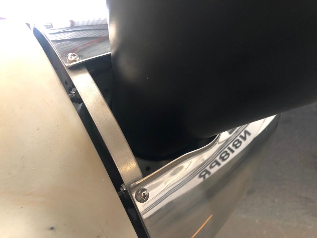
I also need to fabricate filler pieces to fit behind the blades, but that can happen down the road a bit.

