Fired Up Audio Panel and GTN 635

I stopped by the avionics shop this morning and had them swap a couple of audio inputs in the harness before I started wiring it into the airplane.  After work, I installed the connectors in the back of the trays and ran all of the ground lines.  I temporarily hooked up the power lines to the battery buss and installed some fuses to fire them up.  The map page showed No GPS Position, but that wasn’t surprising since I hadn’t connected the GPS antenna.

I installed a BNC connector on the COM antenna cable and a TNC connector on the GPS antenna.

I also plugged in the SD card and updated all of the databases.  They’re all current (at least for a few more days).

Even in my garage, the GTN had no problem acquiring 6-7 satellites within just a few minutes.  Subsequent restarts allowed the GTN to locate itself much faster since it already had an idea where it was.  The red X over the COM frequencies is because I didn’t plug in the fuse for the COM power line.

I had to fire up the SkyView screens to get an idea what the whole panel will look like.  The SkyView and GTN aren’t talking to each other yet, but there are only a handful of wires to hook up to make that happen (ARINC and serial).  The only other GTN wires that need to be hooked up are the serial outputs to the transponder and ELT as well as the dimming wires.

Finished Wiring SkyView Network

With the screens in place, I started hooking up the serial ports to the interconnect bus I made.  The top connector is for the left SkyView screen.  The next one down is for the right SkyView screen.  The third is for the other accessories in the aircraft (SkyView GPS, transponder and ELT).  The fourth will be for the GTN 635 and the bottom one will be for the audio panel.  I haven’t hooked up the SkyView audio outputs or dimming input/output since the SkyView install manual says not to until they’re supported in software.  When this is eventually supported, all I will have to do is plug the appropriate wires into the appropriate holes to hook them up.

I also finished fabricating the SkyView network cables.  Here is the connection between the EMS and the ARINC-429 box with a tee over to the left SkyView screen.  If you look closely, you’ll notice that the connector on the ARINC box (on the right) has thumb screws, while the one on the EMS has small screws that need a screwdriver.  I’ve swapped most of the thumb screws for small screws, but left a few where access is restricted.

I bypassed the VP-X temporarily and fired up the SkyView screens.  Initially, the left screen was running 2.6 (I think) and the right screen was running 3.1.1, so not everything was working properly.

The left screen was showing proper attitude, but no synthetic vision.

The right screen was showing a position fail indication, but that was expected since the serial ports haven’t been hooked up on the right screen yet.  The engine monitor seems to be working properly.  The manifold pressure is showing 29.7 inches of mercury.  The oil temp, #1 & #3 EGT/CHT temps and battery voltage are also indicating correctly

After a software update and reboot, the left screen has a valid GPS fix which caused the PFD to start showing synthetic vision.

The right screen still has the position fail indicator though.  Time to hook up the serial ports.

You can see that all of the connections on the top two connectors are identical.  The SkyView installation manual says that all of these connections should be shorted together between the two screens.  By hooking them up to the same pins on separate connectors, this happens automatically.  For example, the rightmost pins on the top and bottom row of each connector are for the #1 serial TX & RX lines.  Since both displays are connected to these pins on different connectors, their TX & RX lines are shorted together.  On the third connector down, you can see the transponder serial lines are connected to these same pins.  This allows both displays to send and receive data to/from the transponder.

After hooking up all of the serial lines from the right screen, both displays now have position data.

Mounted SkyView Screens

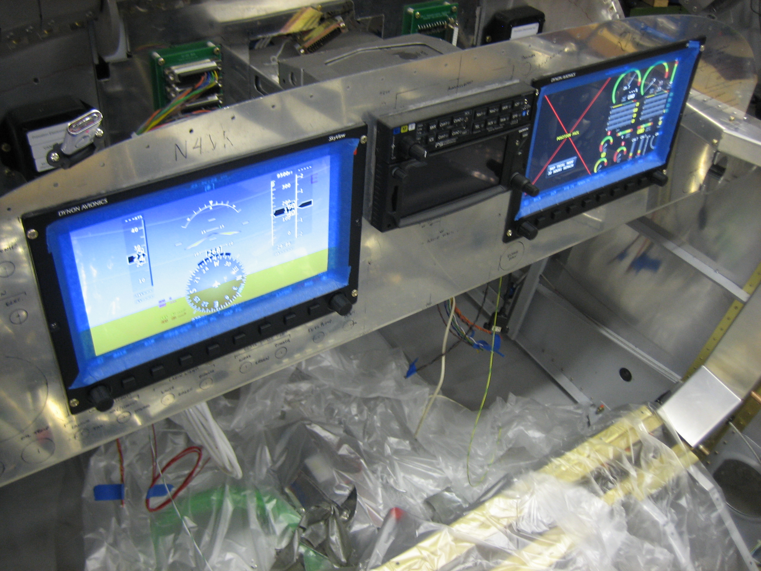
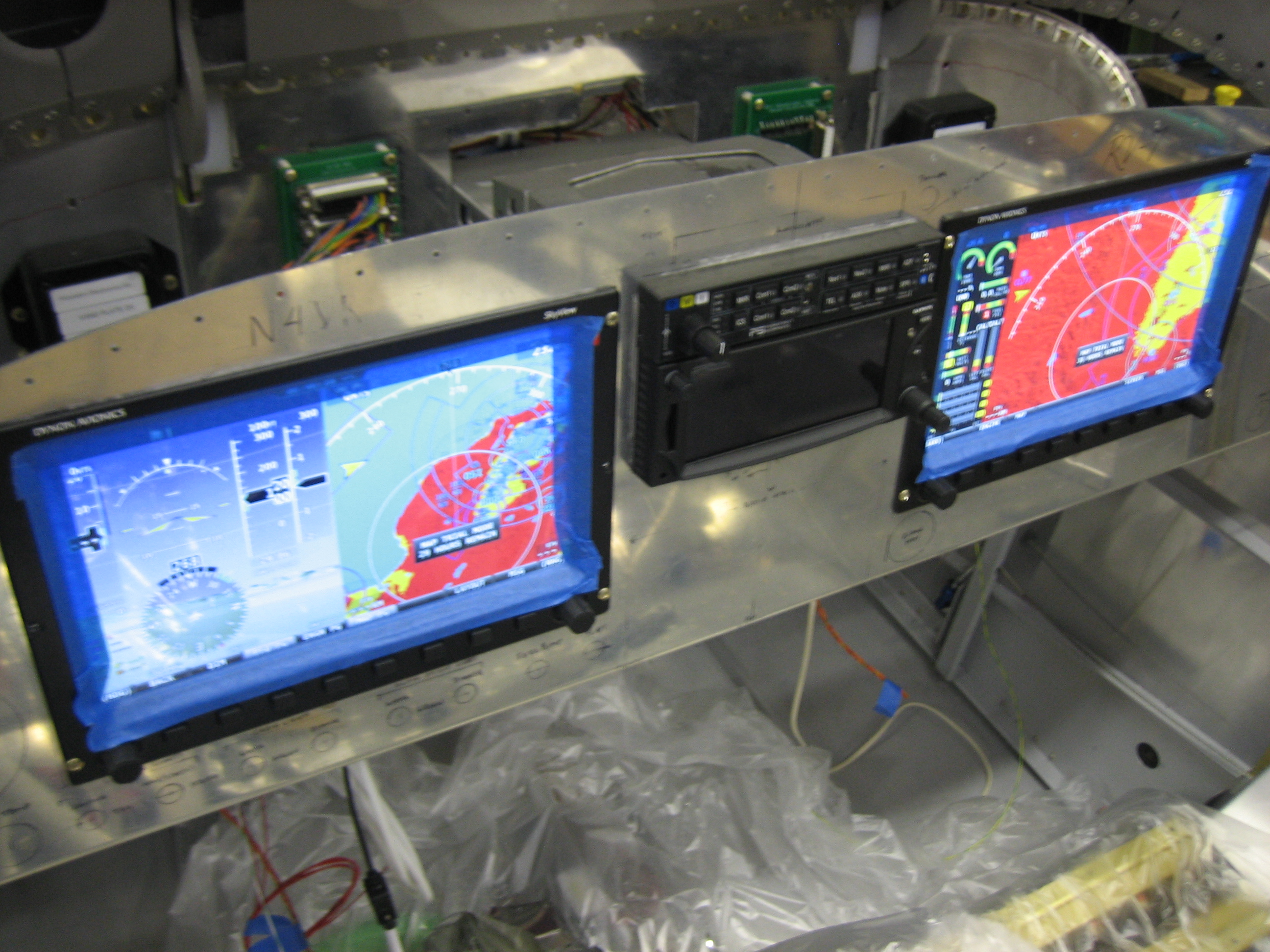
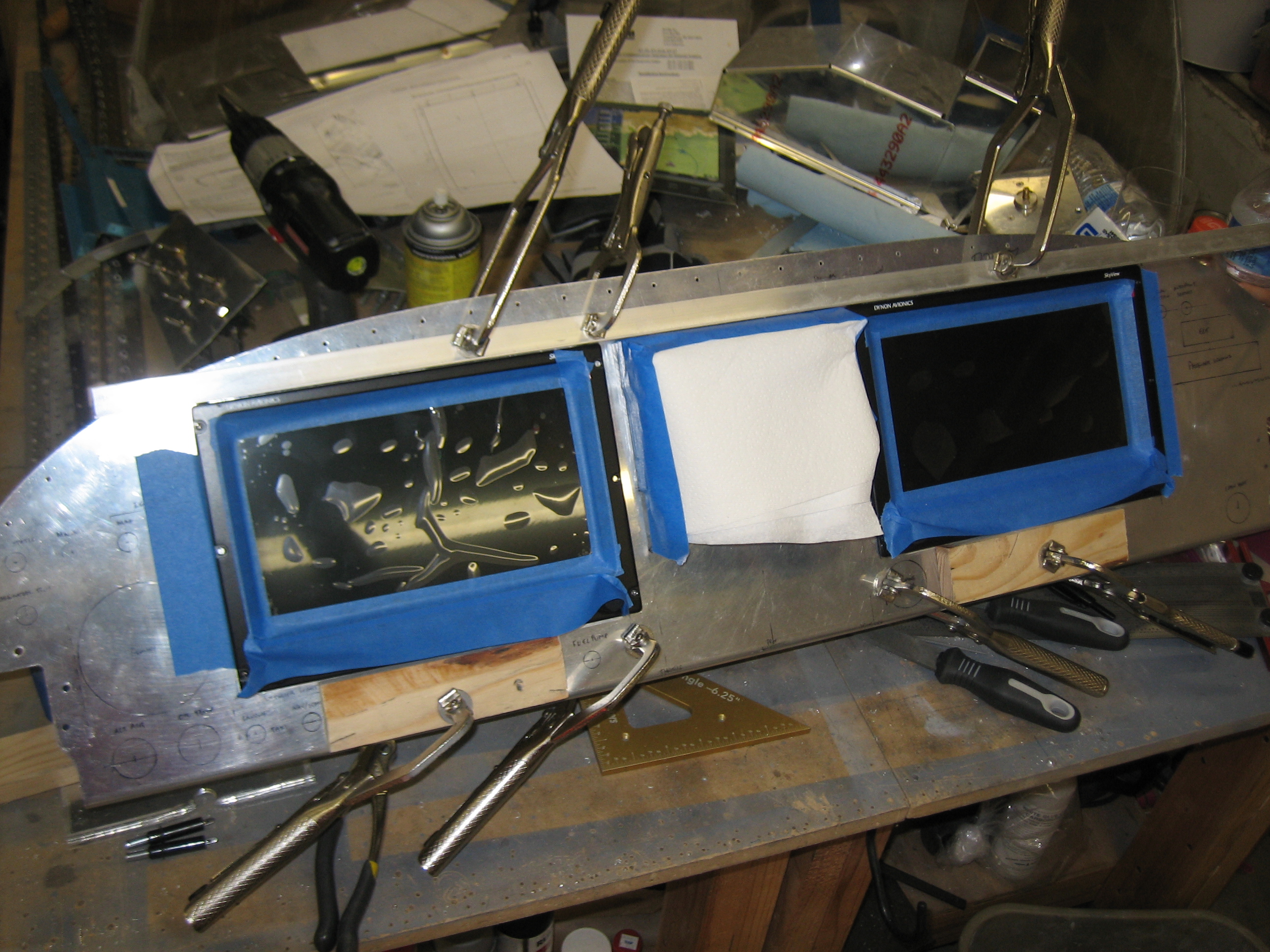
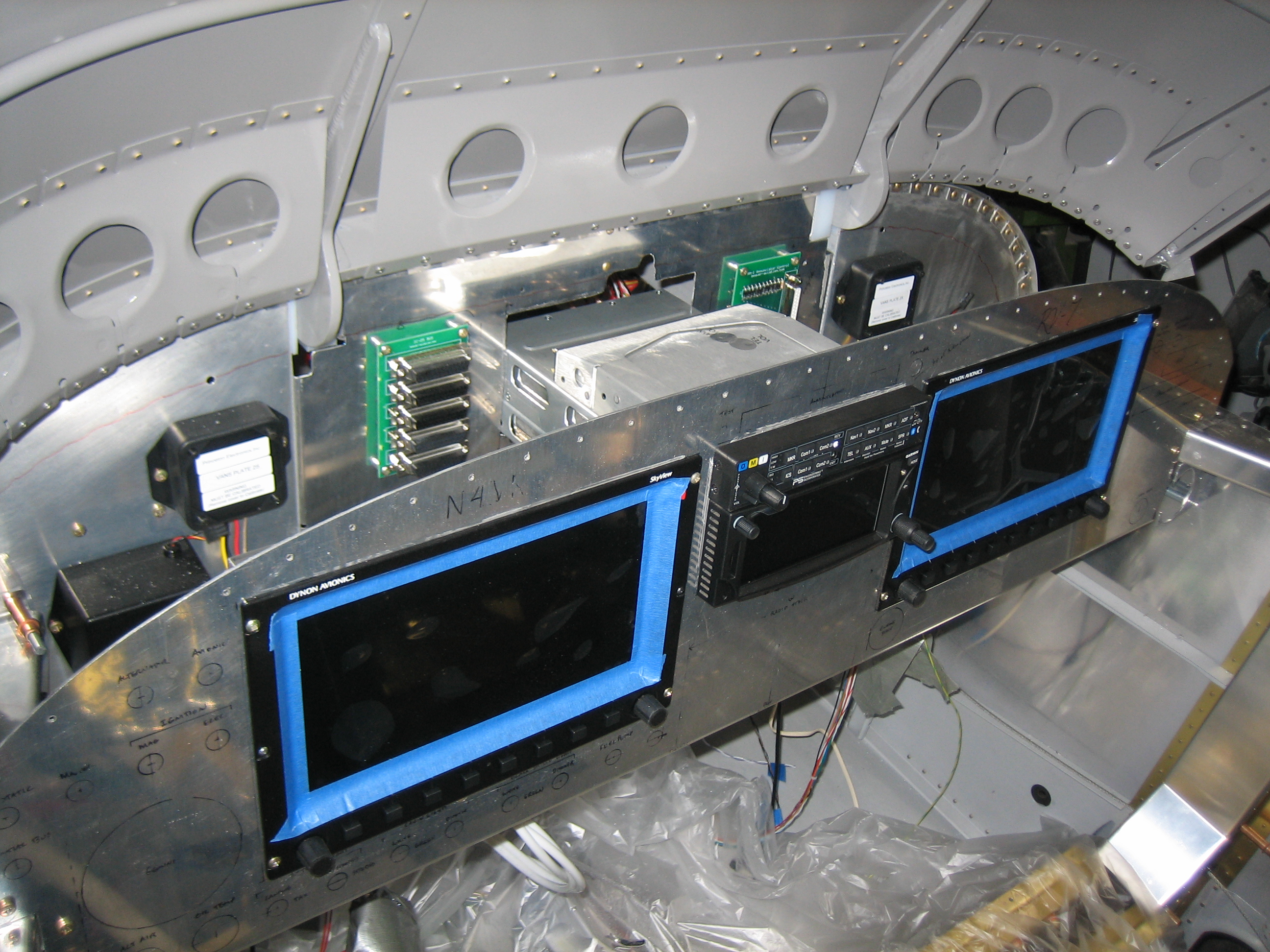
After enlarging the SkyView screen holes slightly, I clamped a straightedge along the top of the radio stack and made sure it was aligned with the bottom edge of the panel, then pushed the SkyView screens up against the straightedge and moved them as far inboard as they could go.  I used a couple of wood blocks to hold the SkyView screens in position while I drilled a couple of the mounting holes to lock in the final position.  You can see I used some extra tape and a paper towel to keep any metal shavings out of the avionics.

I fit the panel in the plane to determine where the ribs need to be mounted.

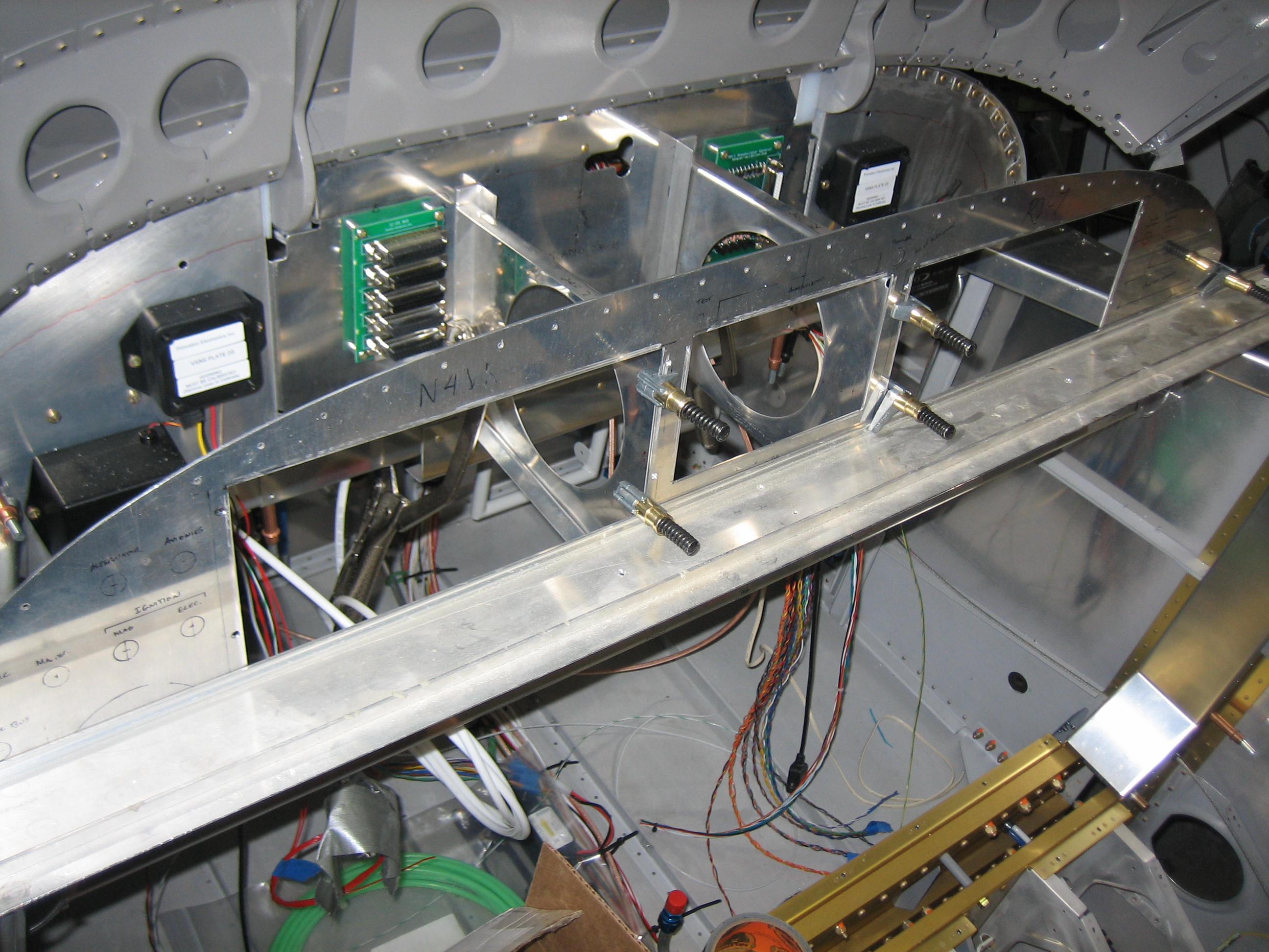
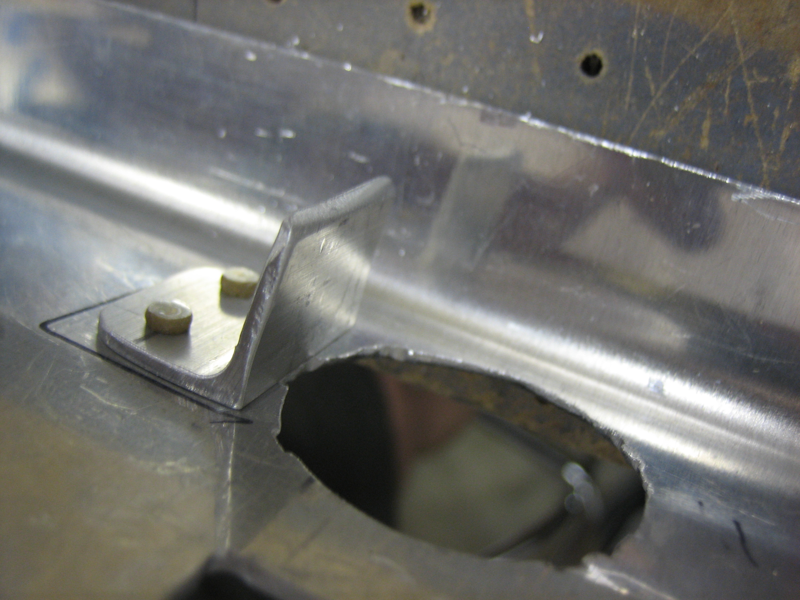
I’m going to use some 1/16″ angle to attach these ribs to the subpanel.  Some additional 1/16″ angle on the other side of the subpanel (mounted horizontally) will be used to box in the hole in the subpanel to strengthen it.

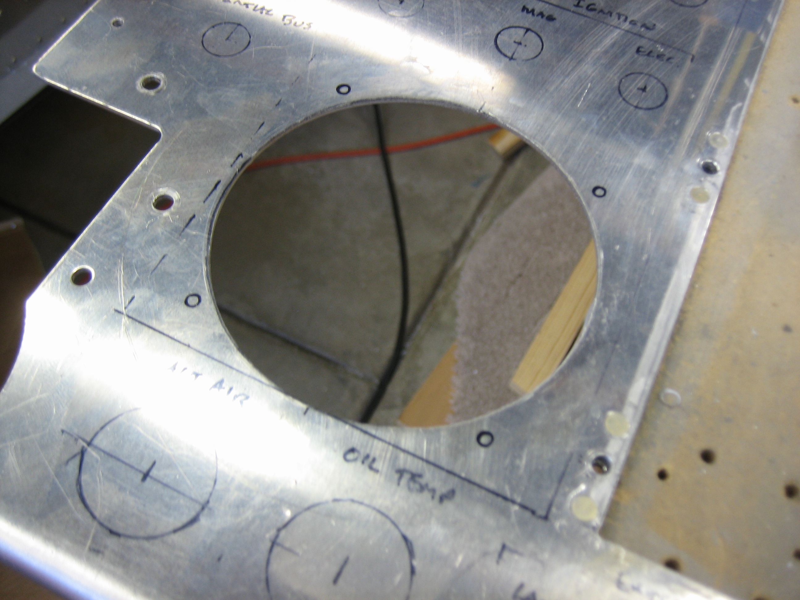
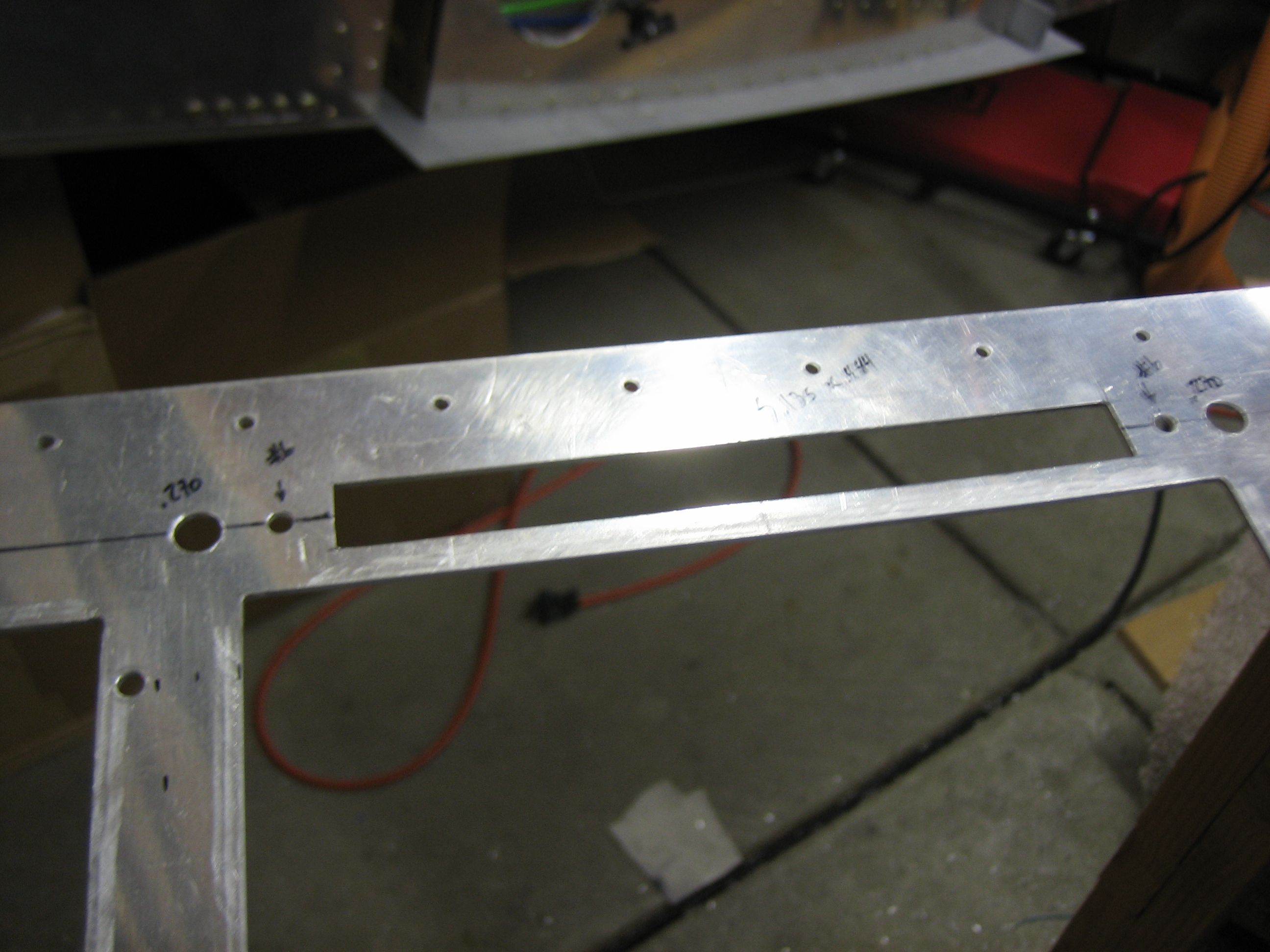
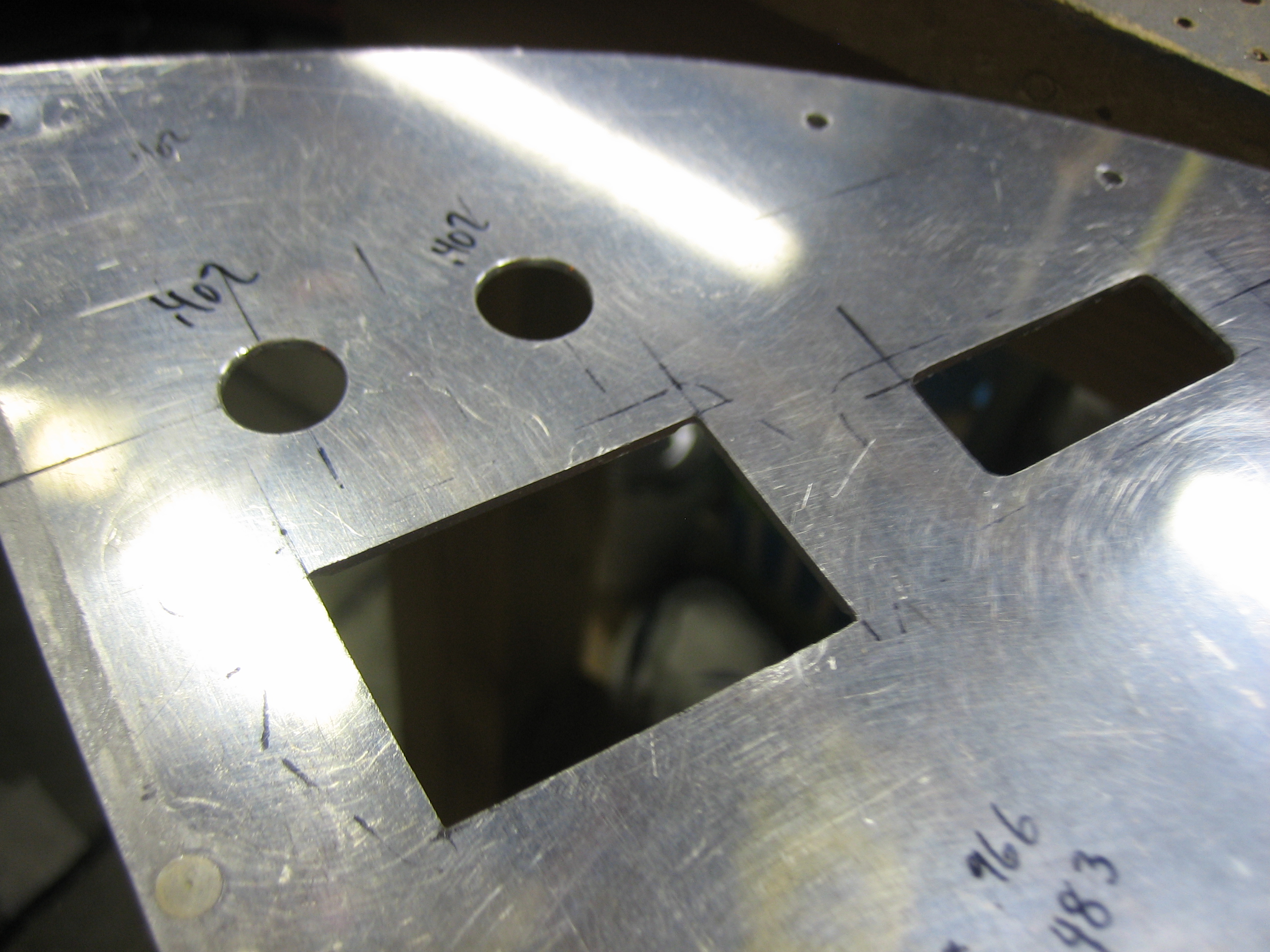
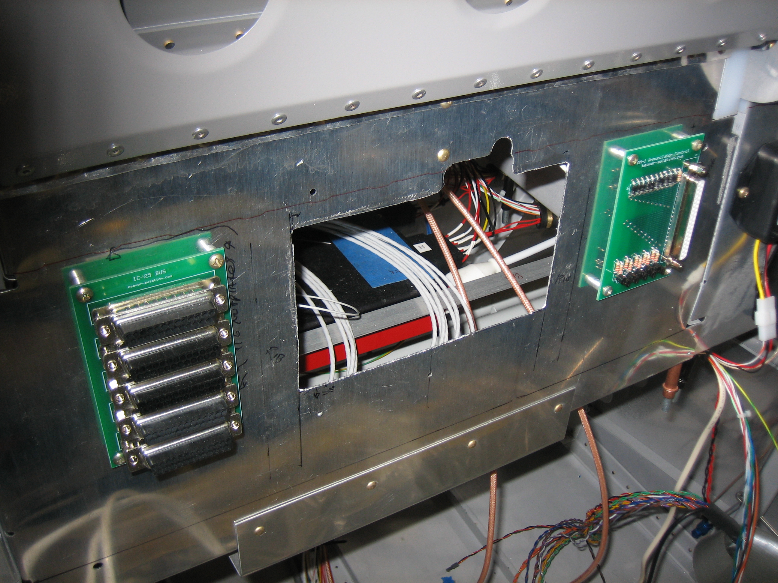
A few minutes with various nibblers and snips and I have this hole in the subpanel.  The sides and bottom edge are aligned with the sides and bottom edge of the radio stack hole in the panel.  The top edge is 5/16″ lower than the top edge of the hole in the panel since the audio panel tapers down in the middle and is pretty short.  Only the wiring harness will need to go through this hole.

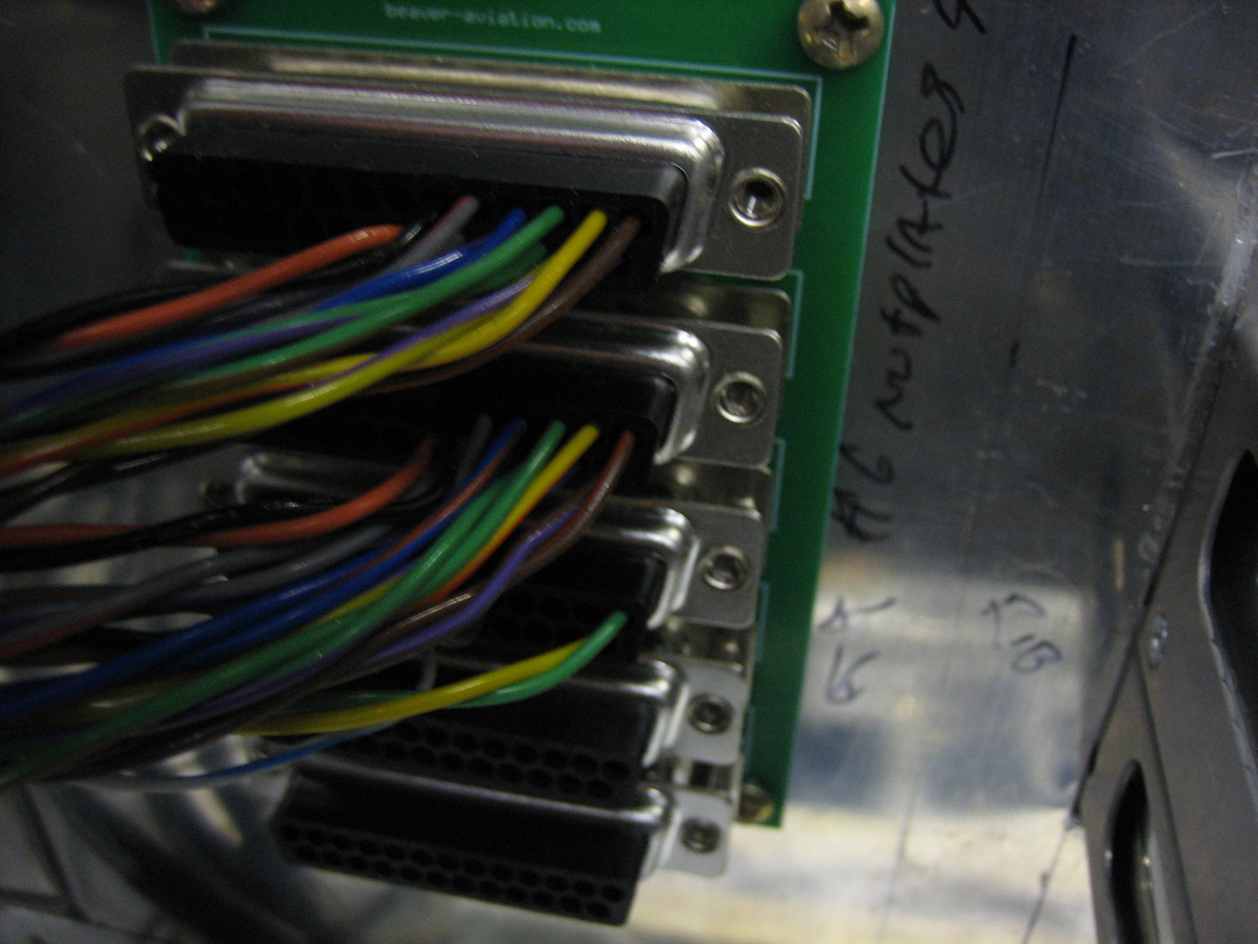
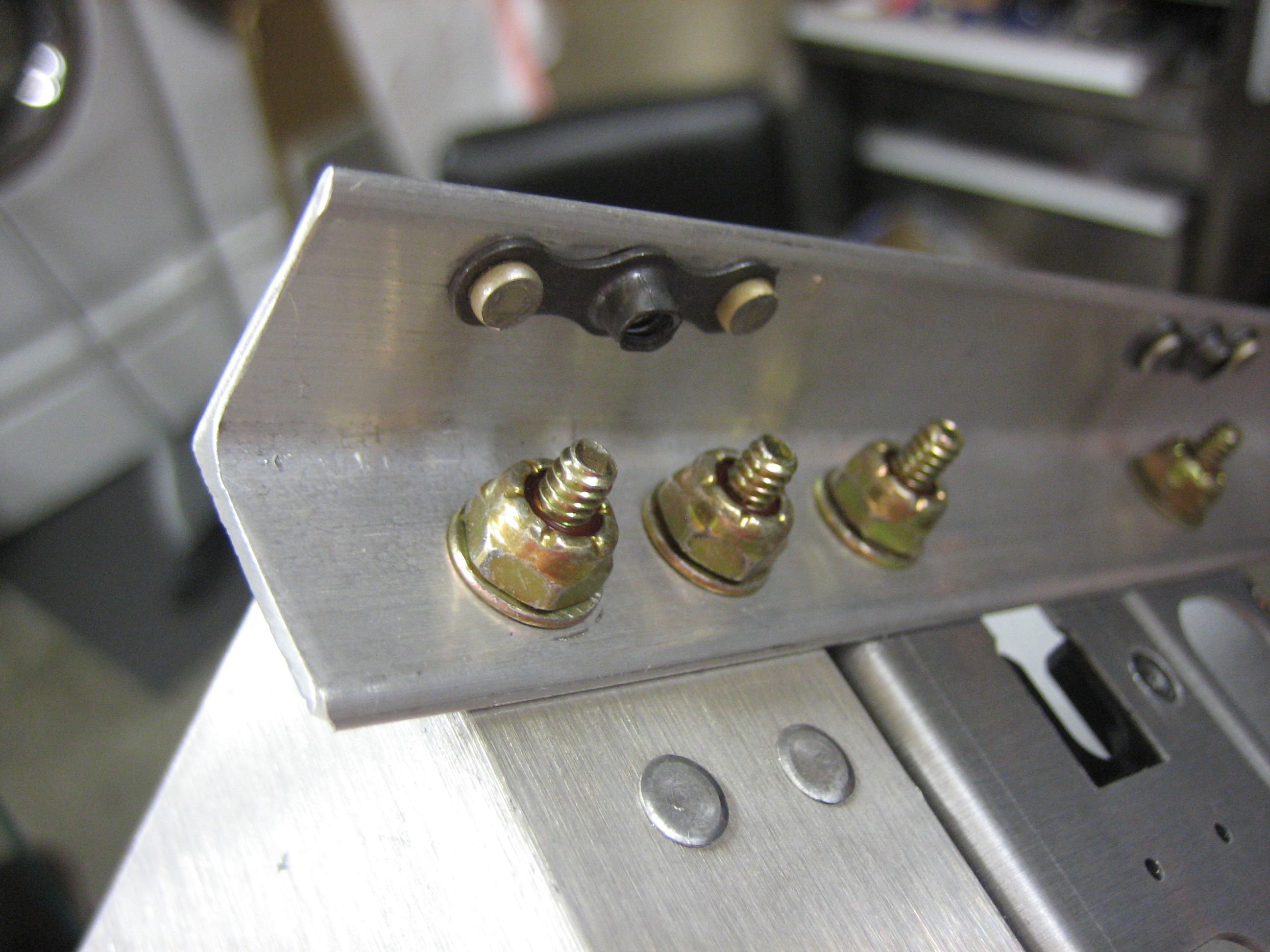
I installed #6 nutplates in the outer SkyView mounting holes.  You can also see in this picture that I filed a radius into each corner of the screen cutout to avoid a stress riser.

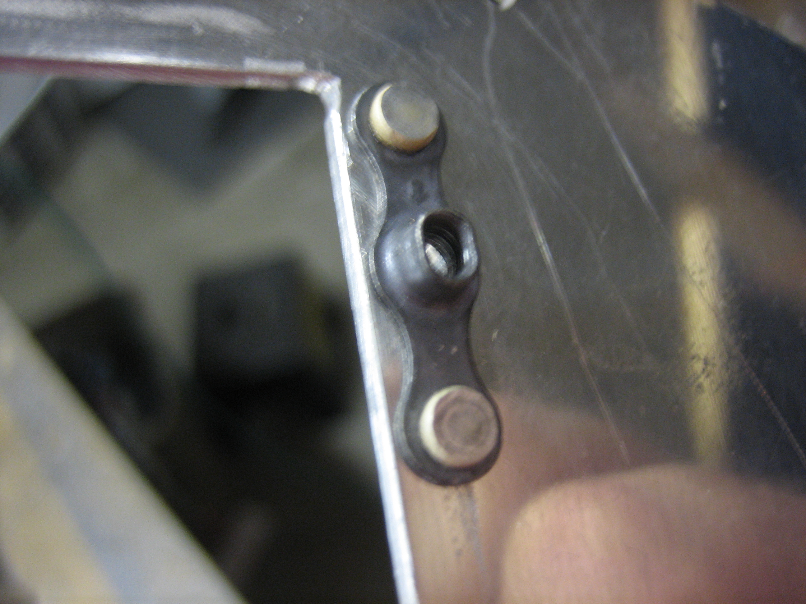
For the radio stack, the nutplates are installed in the mounting rails.

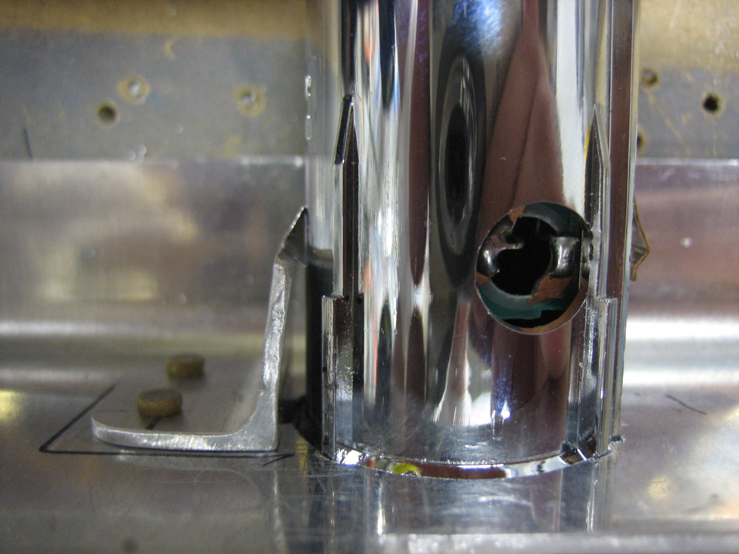
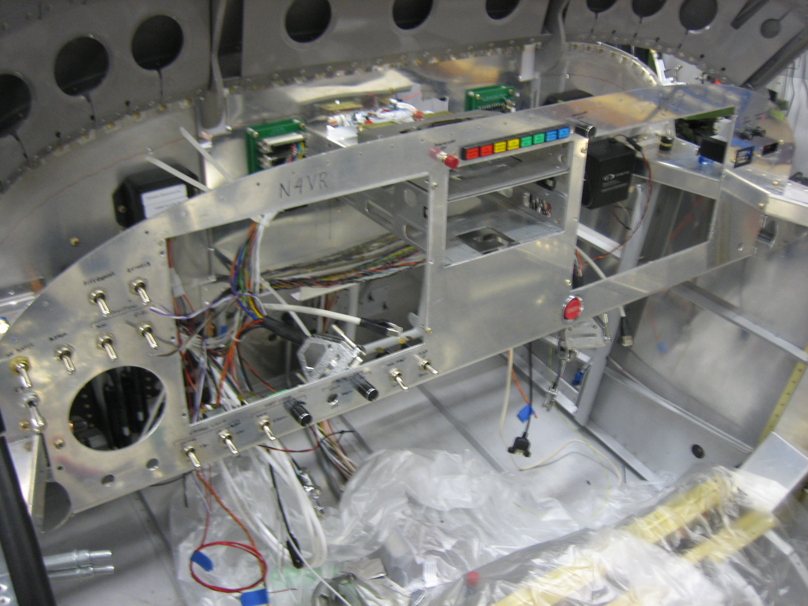
I test fit the panel in the plane.  The hole in the subpanel is a little right, but it’s in exactly the right spot.

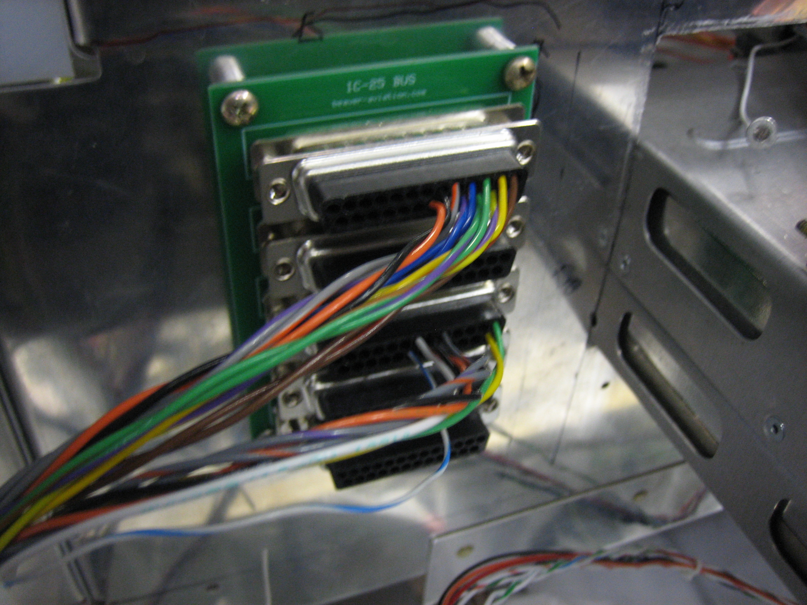
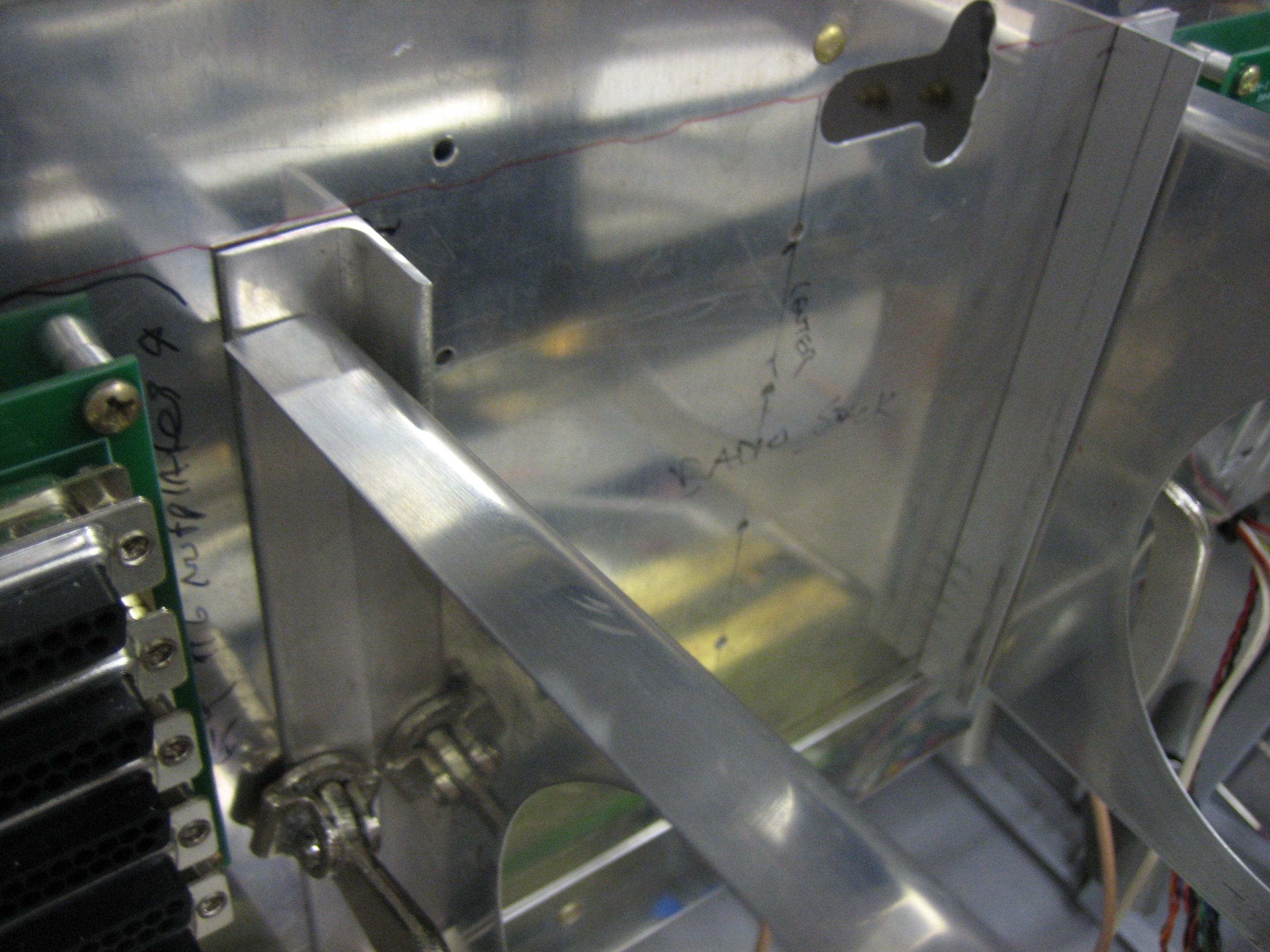
You can see how tight the sides are, but the opening on the top will be perfect for the wiring harness to slip through.

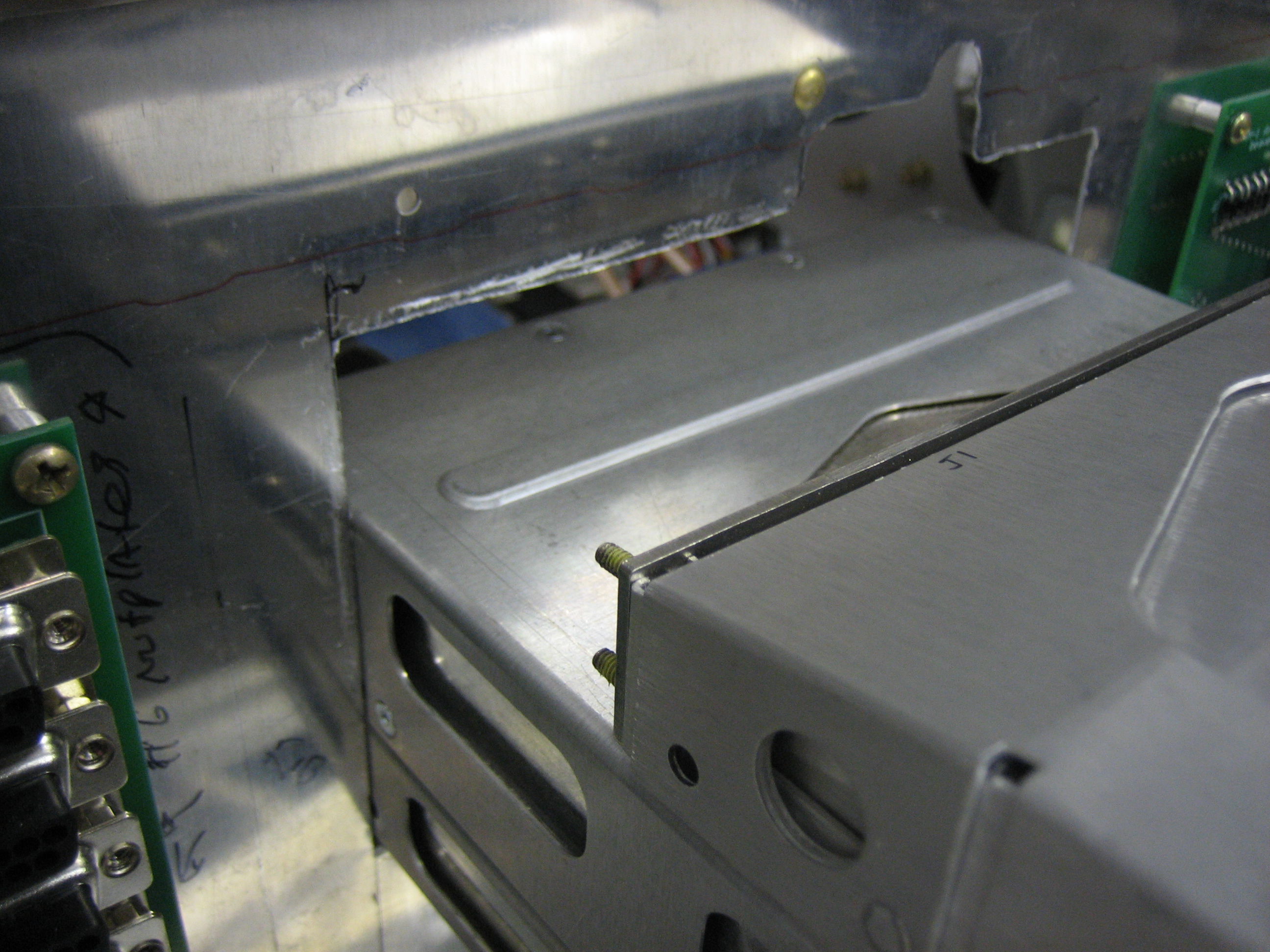
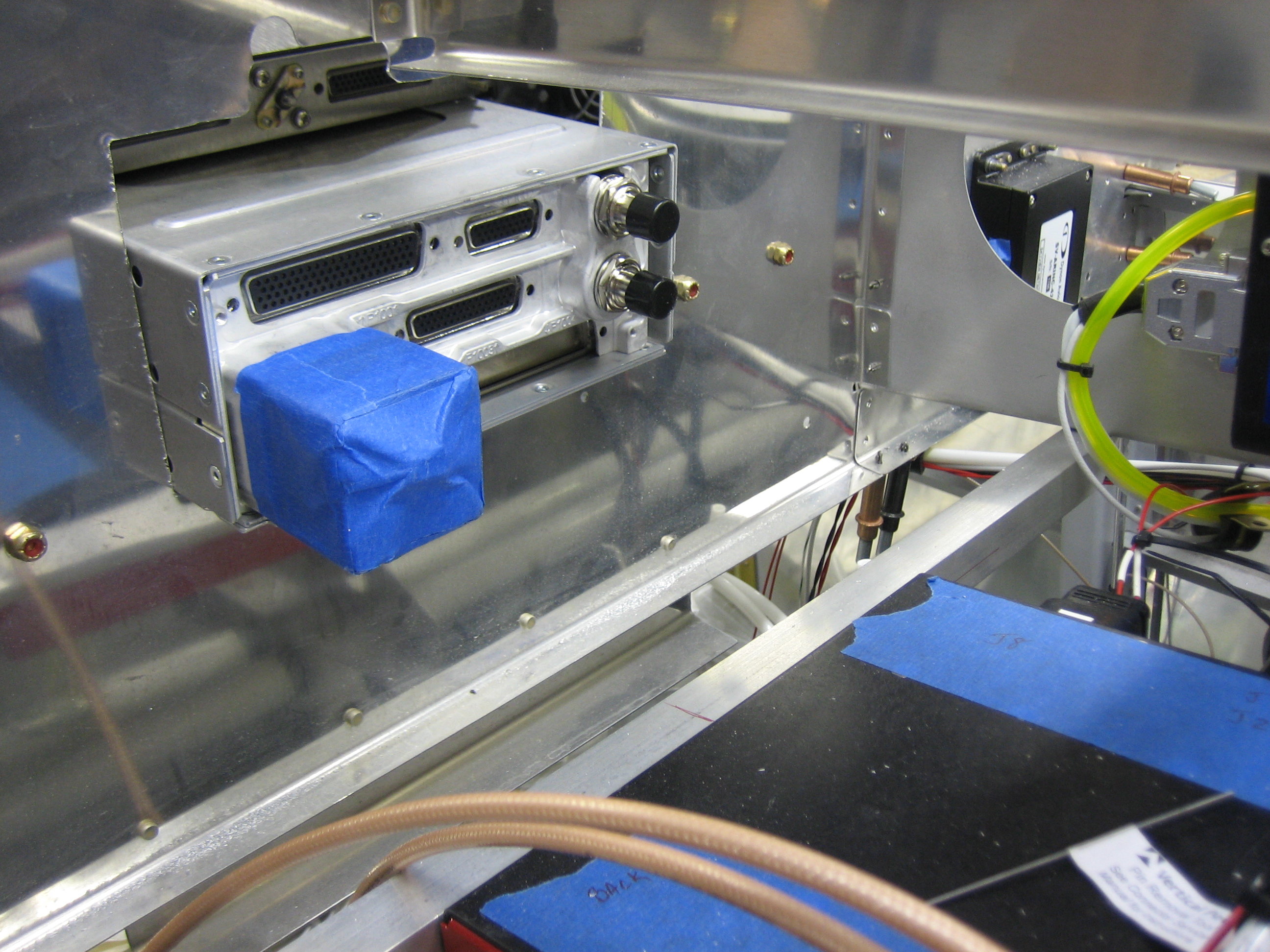
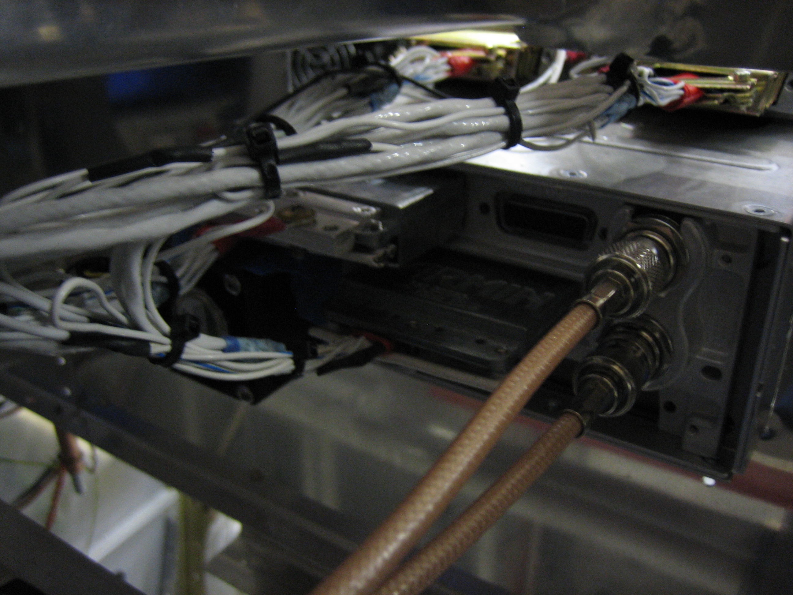
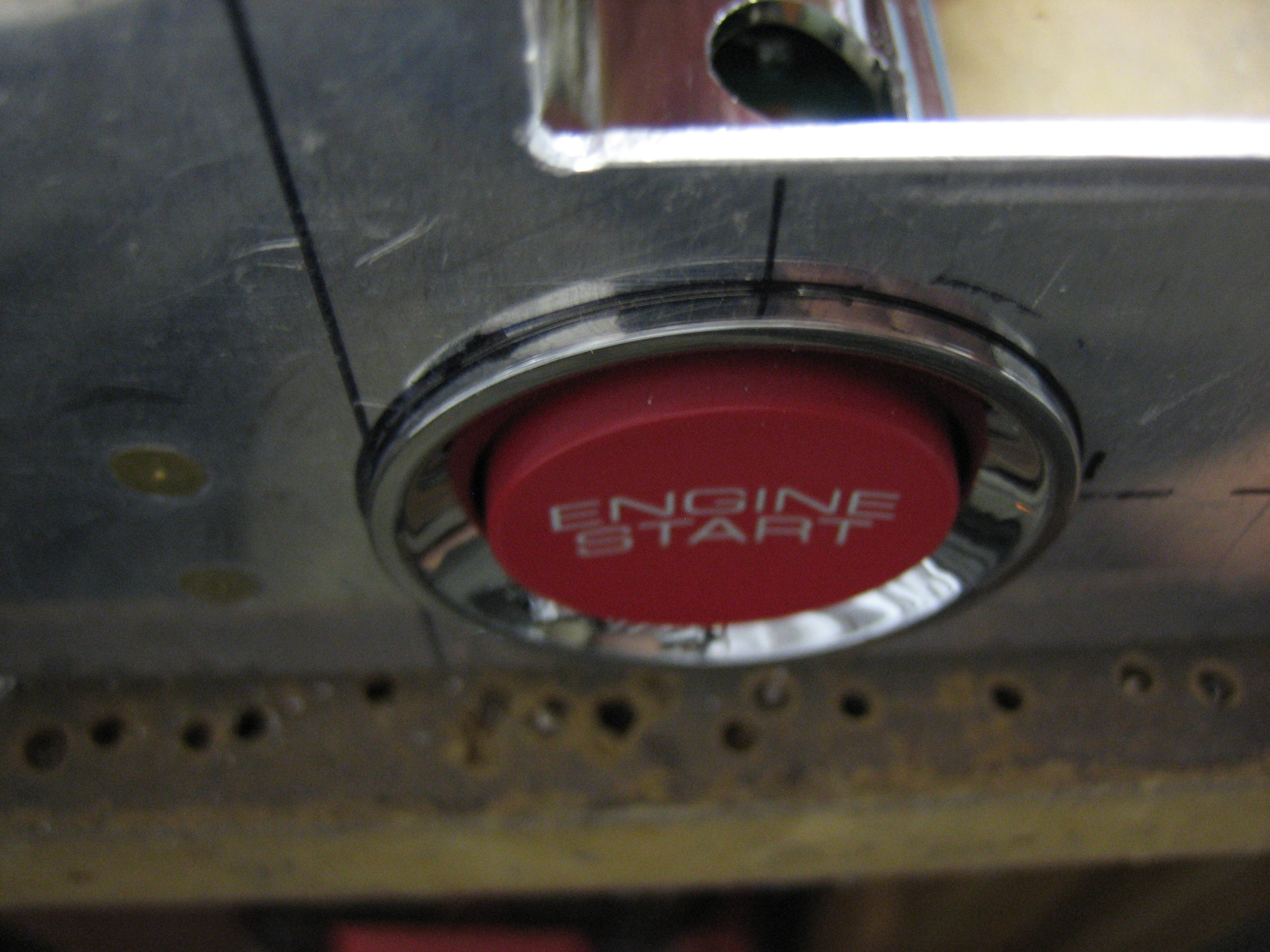
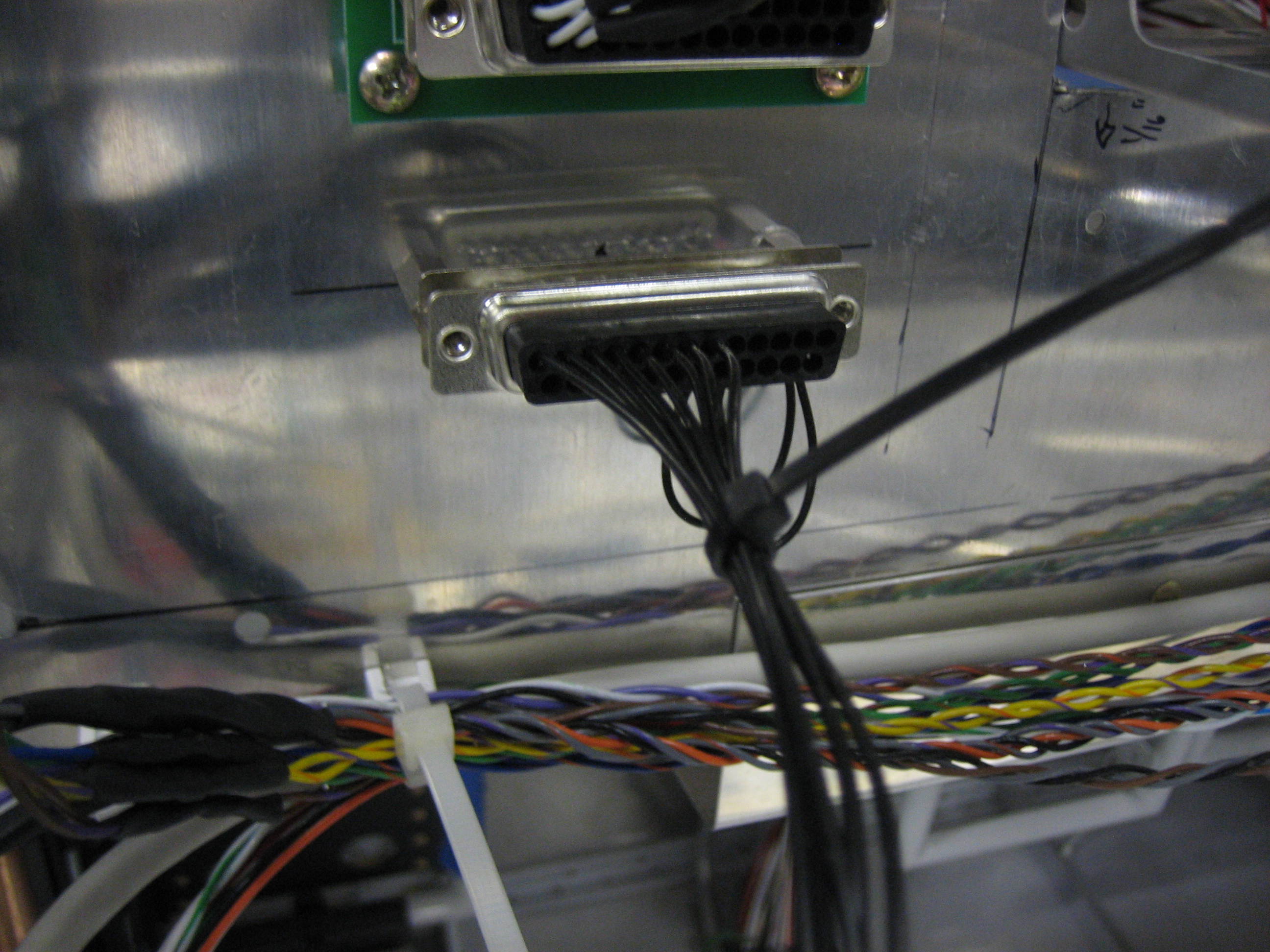
The clearance on the front side of the subpanel is great.  Plenty of room for the connectors to stick out and for the wiring harness.

Cut Holes for SkyView Screens

I extended the hole for the radio stack downward by 3/32″ and then cut the holes for the SkyView screens so that the top edges of the screens are aligned with the top of the audio panel.  The holes need a little more filing since the screens are a pretty tight fit right now, but they’re close.  Once I’m happy with the fit, I can drill the mounting holes which will simultaneously lock in the position of the SkyView screens and radio stack mounting rails.  Everything else will be mounted relative to these items.

Started Cutting Panel

I wanted to get started cutting the panel tonight.  First up though, I needed to fill two of the holes that are normally used to attach the panel to the ribs.  Since I’m moving the ribs inboard, these will no longer be used.  The top holes on each side (and the one in the middle that is normally used for the canopy ejection handle) all fall within avionics cutouts, but the bottom holes on each side will be visible beneath the SkyView screens.  I countersunk the holes and installed AN426AD5-4 rivets in them.  When I prep the panel for paint, I’ll sand/fill this so that it will be invisible.

I then cut out the hole for the avionics stack.  The hole is really tight vertically now (and just right horizontally).  I’ll extend the bottom edge of the hole down 1/16″ or so to make a little more room.

Along the side, you can see that the avionics are completely flush with the panel.  Once I move the stack down a tiny bit, I’ll line up and cut the holes for the SkyView panels.

Fabricated Avionics Stack Mounting Brackets

After carefully aligning the trays, I drilled some 1/16″ angle to them so that they can be mounted to the instrument panel.

The 1/16″ angles are set back by the thickness of the instrument panel.  Using a piece of scrap here the same thickness, you can see that the faceplates of the radio will be flush with the front of the panel once installed.  Next up will be to cut the hole in the panel and subpanel for the avionics stack.

Received Avionics Stack

I picked up my avionics stack from Aerial Avionics today.  They’re a local company, but they were willing to match a price quote from I got from Stark Avionics.  I got a PS Engineering PMA 8000BT audio panel and a Garmin GTN 635 GPS/COM.

They built the wiring harness as well.  I went through the whole thing so that I could fully understand all of the interconnects.  Other than installing an unnecessary marker beacon antenna cable (which I removed), everything looks perfect.  Despite what looks like a rats nest, these are nicely organized and grouped together according to where they need to be routed in the airplane.  The only mistake I made was forgetting to request that they use red wires for power and black for ground like I’ve done with all of the other avionics in the plane.

Finished Tailcone Wiring (For Reals)

I thought I finished all of the tailcone wiring a couple of weeks ago, but I had forgotten about the OAT probe and ELT antenna cable.  I drilled a new hole in the vertical rib for the antenna cable to avoid too tight of a bend radius.

On the right side of the fuselage, the cable follows the tubing run and then jumps over to the tailcone wire bundle and follows it into the conduit.

I also installed a couple of adel clamps under the seat.  This one supports the wires and tubing as they come out of the front end of the right conduit.

I installed another one on the other side of the same rib to keep the tubing from interfering with the aileron pushrods.

I also installed a couple of zip-tie bases in the aft flap cover to support the flap motor and position sensor wires.  There are not installed permanently right now, but I wanted to anchor them so that I could determine the final wire length.

Finally, I recreated my upper left switch layout with some scrap aluminum to make sure I was happy with the spacing.  I spent a few minutes playing with it and I think it’s perfect.  The spacing I settled on was 1 1/4″ horizontally and 1 9/16″ vertically.

Ramp Crossing Bends and Instrument Panel Prep

I trimmed the forward ends of the ramps to within 1/2″ of the final dimension and them marked them for the crossing bends.  These bends allow the ramps to follow the slope of the cowl inlet.  The ramp on the left side is pretty deep since the air filter will be installed here.

The ramp on the right side is quite a bit shorter since the #1 cylinder is farther forward.

From the back side, you can see that the ramp follows the slope of the cowl inlet.  The ramp will get trimmed to be exactly flush with the inlet and a piece of baffle seal material will bridge the gap to prevent air from leaking.

I also trimmed off 1/2″ from the top of the Experimental Air throttle bracket so that I can have a little more knee room.

I’m going to have this TIG welded to the bottom of the instrument panel, flush with the front of the panel.  I’ll grind the weld flat so that this will be a seamless transition once painted.

Trimming Baffles

No pictures tonight, but I went through a few iterations trimming the baffles.  The cowl is quite a bit lower, but still not all the way down.  I probably have at least 1/2″ to go if not more.

I also started trimming the ramps.  I have no idea why they give you so much extra material; you have to cut quite a bit of it off before you can even start bringing the lower cowl up into place.