Resumed Work on Baffles

With the cowling fit, I resumed work on the baffles.  After a little trimming where the baffles fit around the rocker arm covers, I got everything mounted to the engine except for the part behind the spinner.
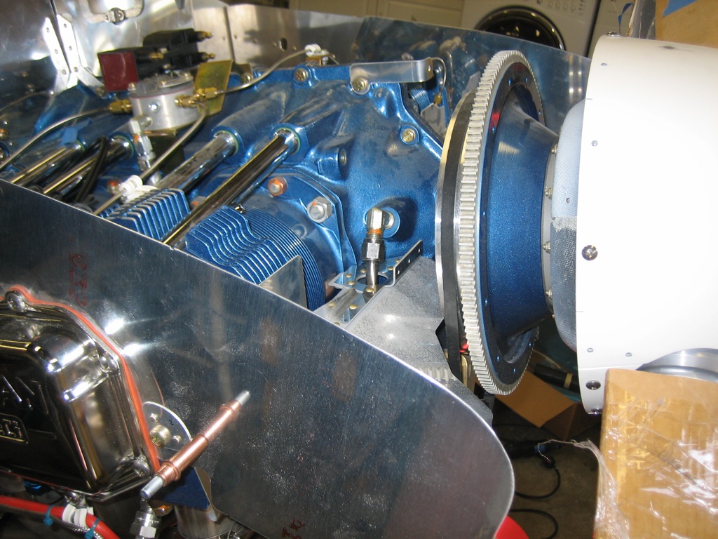
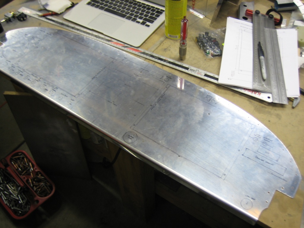
I had previously cut off the flange from the aft baffle support since it pushed the aft baffle walls too far back.  I fabricated I replacement from some 1/16″ angle stock and riveted it to the baffle support.
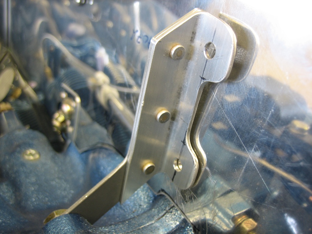
To ensure the aft wall is in the right spot, I clamped a straightedge across it.  I then clamped the bracket to the wall and drilled the holes.
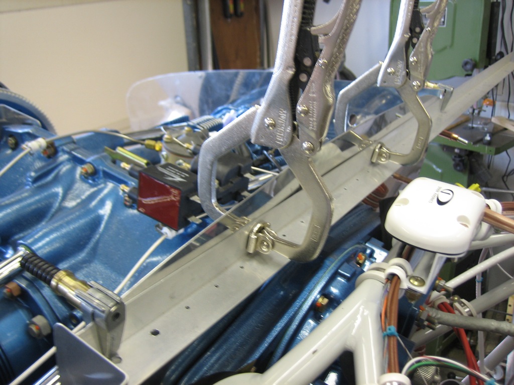
With the aft baffle wall bolted to the support, the back wall becomes very rigid.
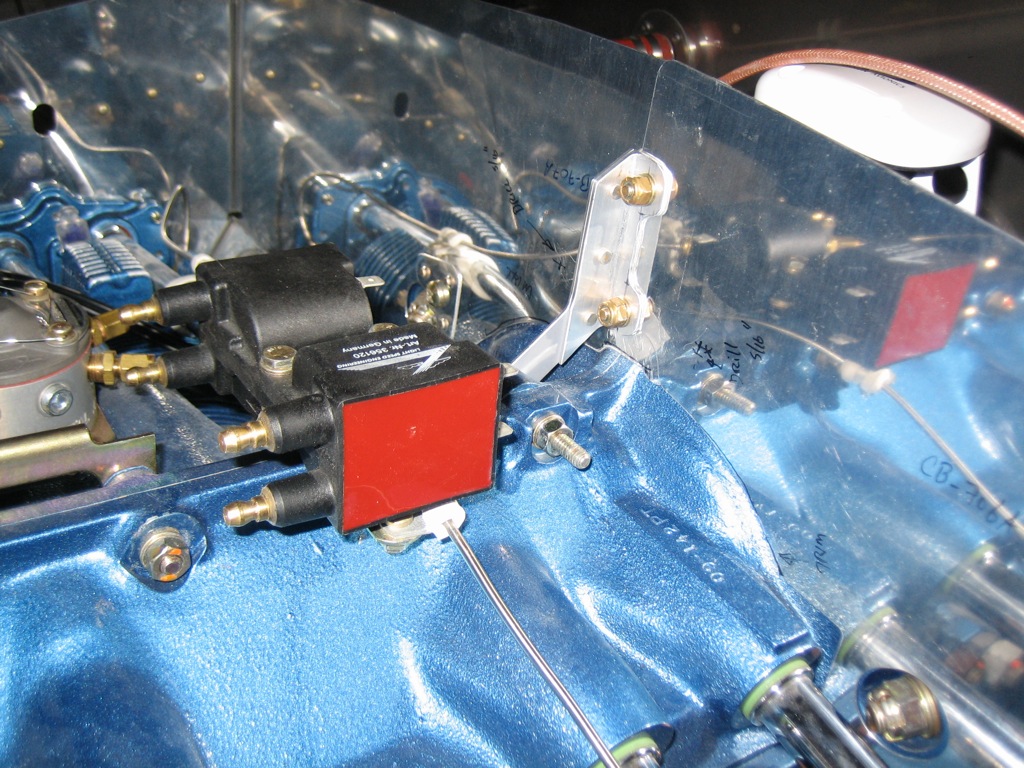
I made the preliminary angled cuts on the ramps and made the necessary bends in the forward side baffles.
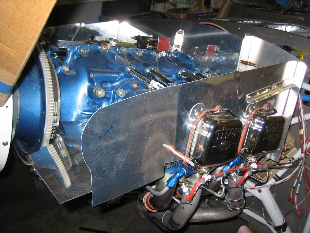
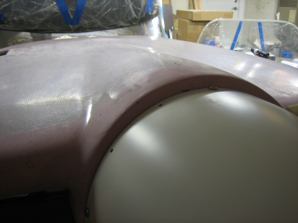
With a little trimming back of the side baffles, I got the cowl to fit down behind the spinner.  You can see that it’s still nearly 1″ too high, so I’m going to have to cut off quite a bit of material to get the cowl to drop all the way down and then further to have the necessary clearance between the cowl and the baffles.  The engine can move around quite a bit due to the flex of the engine mounts, and you don’t want the baffles to contact the cowl.
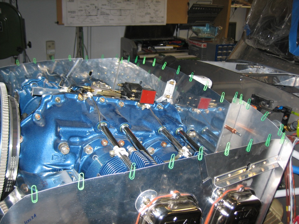
The standard way to trim the baffles is to line the top with paper clips and then put the cowl on top.  The cowl will push some paper clips down more than others. You can then measure down some amount from the top of each paper clip to create a cut line that perfectly follows the curvature of the inside of the cowl.
Installed GPS Mount and Started Instrument Panel

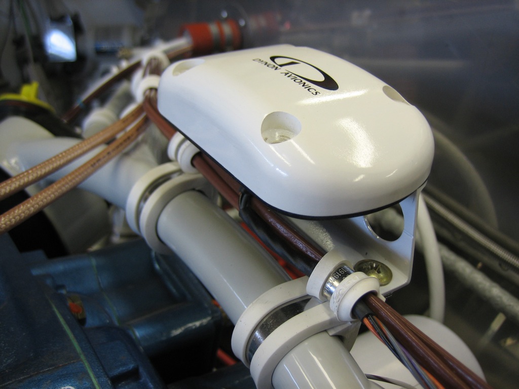
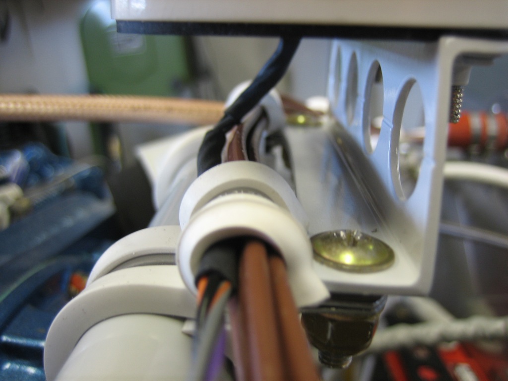
With the mounting bracket painted, I installed it on the engine mount.

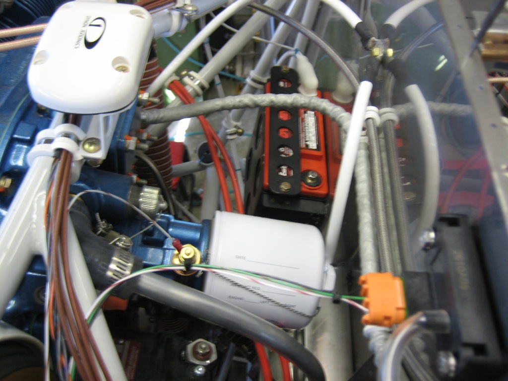
The EGT and CHT wires from cylinders 1 and 3 run under the bracket and pick up the GPS wires.

There is still plenty of access to the back of the engine for oil changes and maintenance.  I like this approach so much better than the shelf that many builders go with.

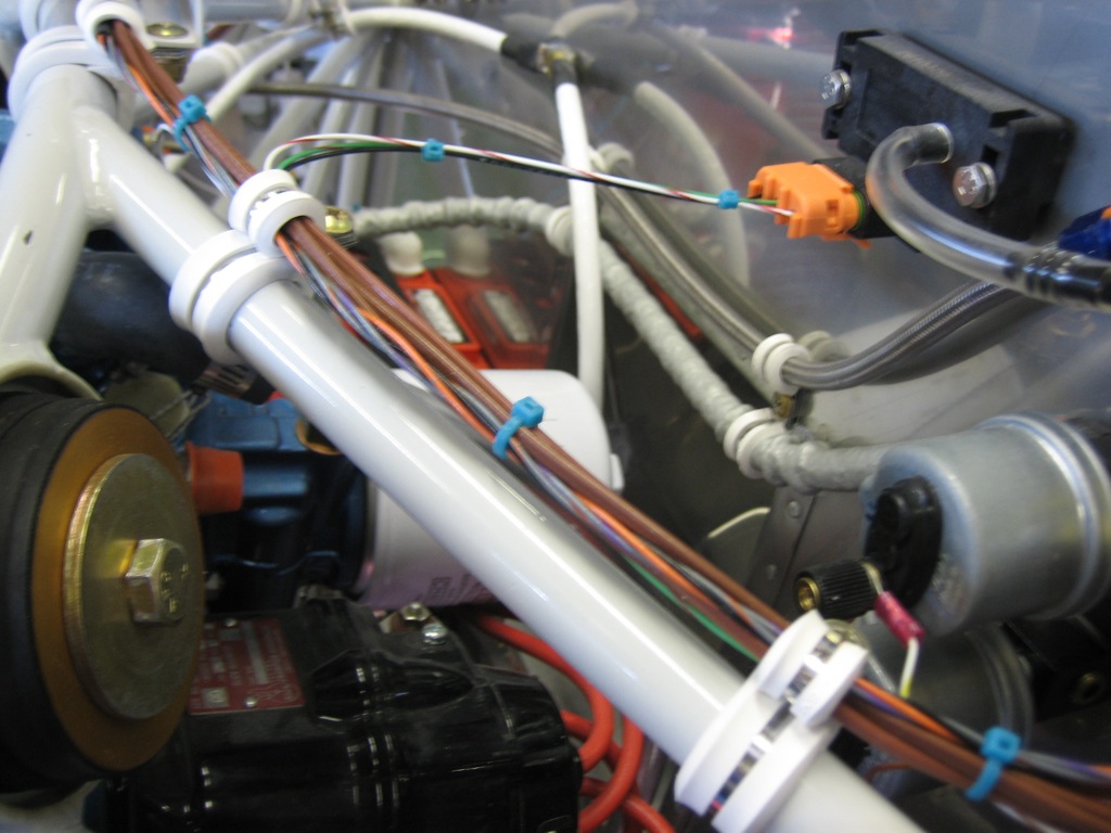
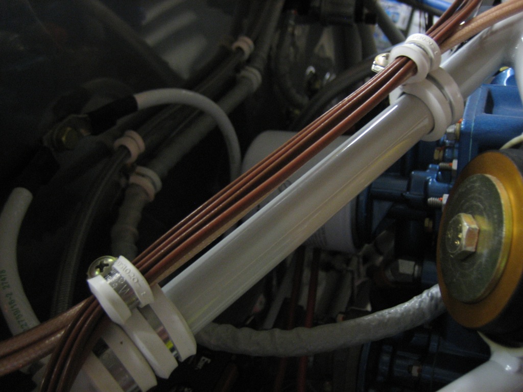
I then finished up securing the wires along the top left engine mount tube.  This bundle picks up the oil temperature sensor, manifold pressure sensor, oil pressure sensor and fuel pressure sensor wires along the way.

I’ve been working on my panel layout on and off for many months.  I’m happy with it now, so I started transferring it to the panel this afternoon.  You can’t see much here, but my computer model was perfect.  Everything fits exactly as it should with the clearances I determined in the computer.

Here’s a rendering of the panel from the modeling software.  The only thing not pictured here is the hobbs meter.

Tidied Up Firewall Forward Wiring

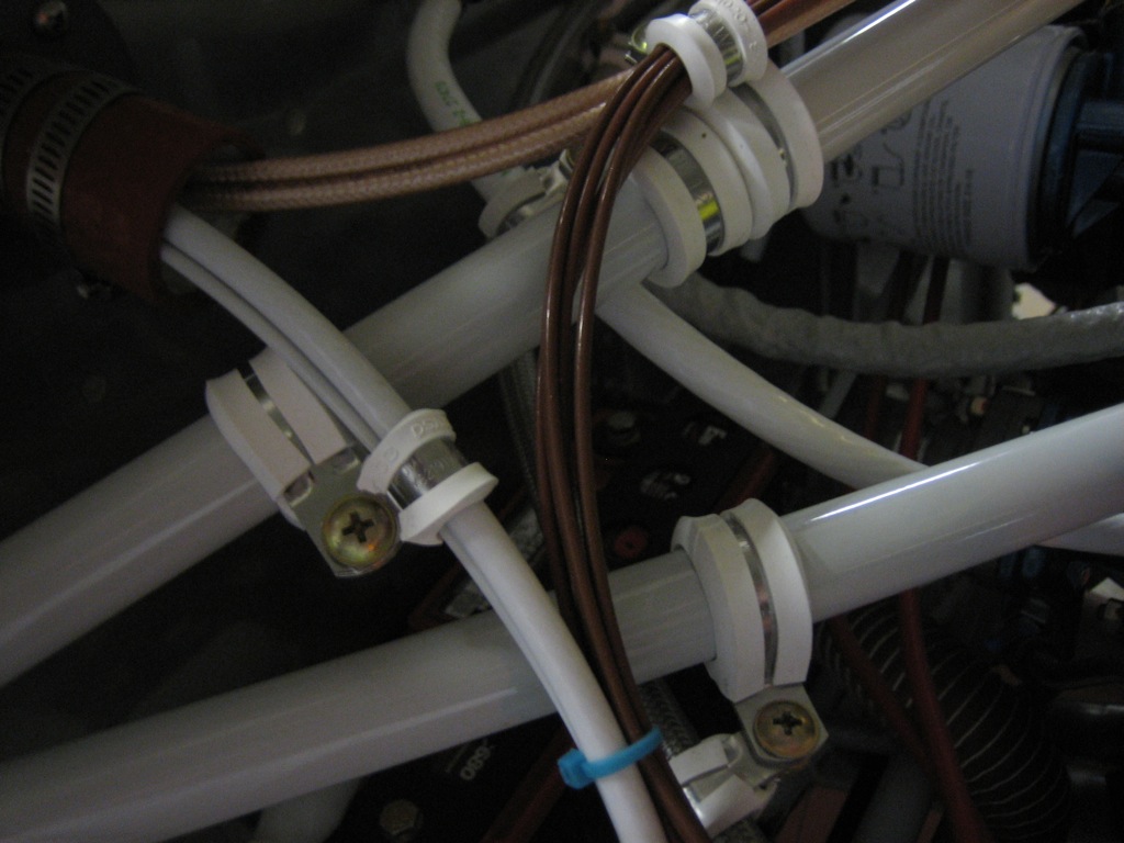
I got an order from McMaster Carr that included some more silicone adel clamps along with some tefzel zip-ties.  I installed a few to secure all of the wires near the right firewall pass-through.

This nicely tidied up the EGT, CHT, and Lightspeed Ignition wires running across the upper engine mount tube.

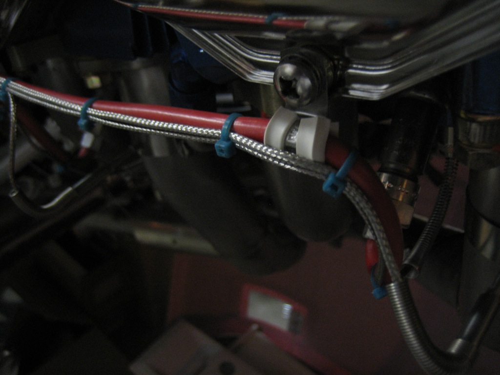
I also replaced a bunch of the temporary nylon zip-ties with the tefzel.  Regular nylon zip-ties are only good up to about 185º F.  Black, UV stabilized zip-ties are better at up to 221º F, but tefzel is good up to 300º F.  There are even higher rated zip-ties such as PEEK which is good to 500º F, but they’re over $3 per zip-tie!  All of the wire insulation in the plane is also tefzel insulated, so if it’s hot enough that these zip-ties melt, I’ll have other problems.

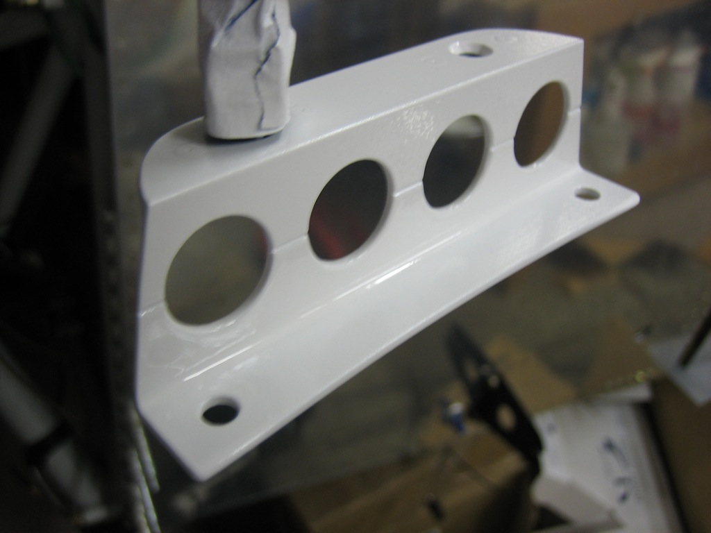
I also finished up the Dynon GPS mounting bracket.  I put a gentle radius in the lower flange to follow the curve of the engine mount and drilled a few lightening holes.  I then primed and painted it gloss white.