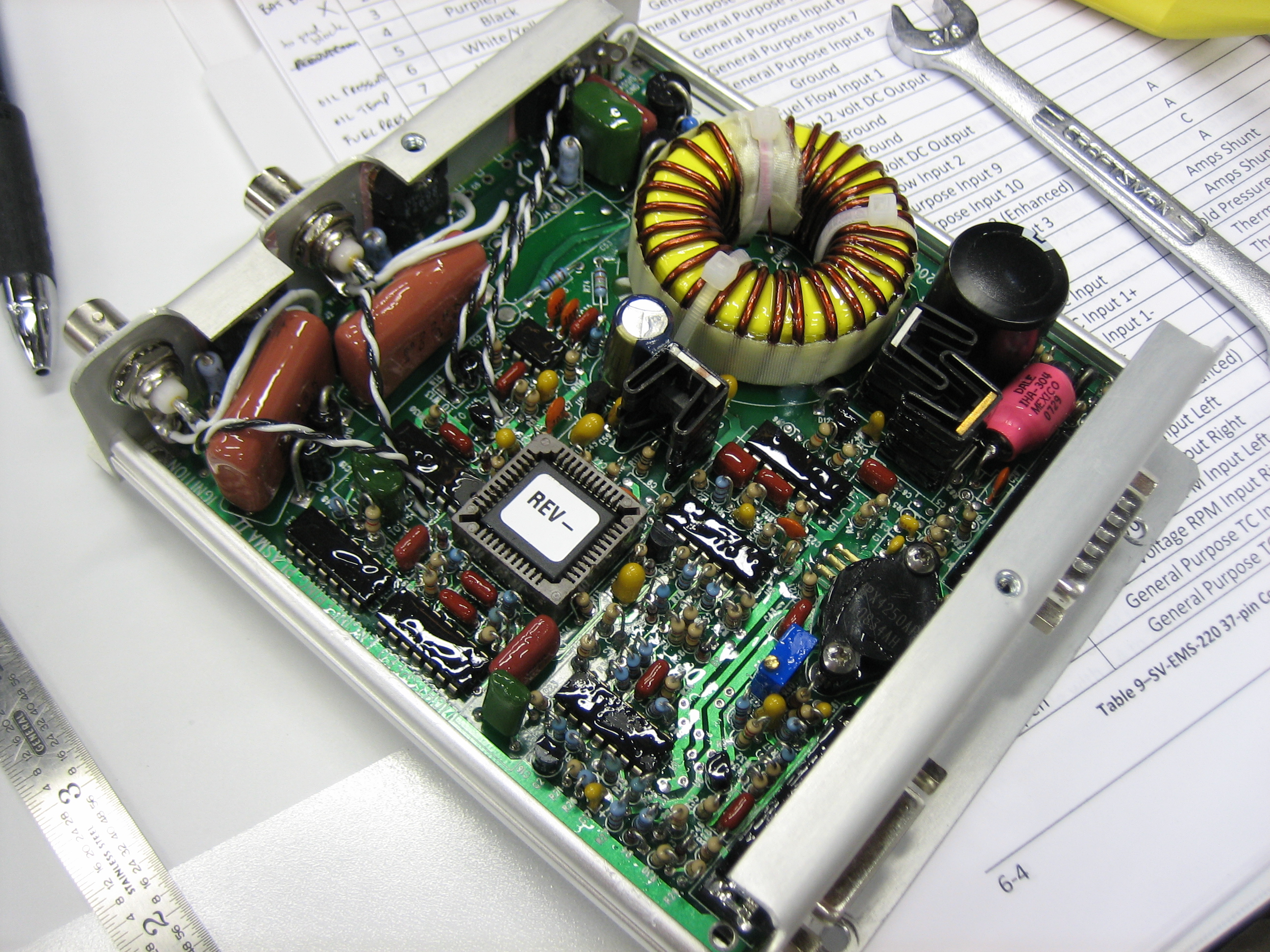
I ordered three of the solid state dimmer circuits from Perihelion Design. They’re completely self contained and use a LM317T chip to regulate the voltage to the lights.
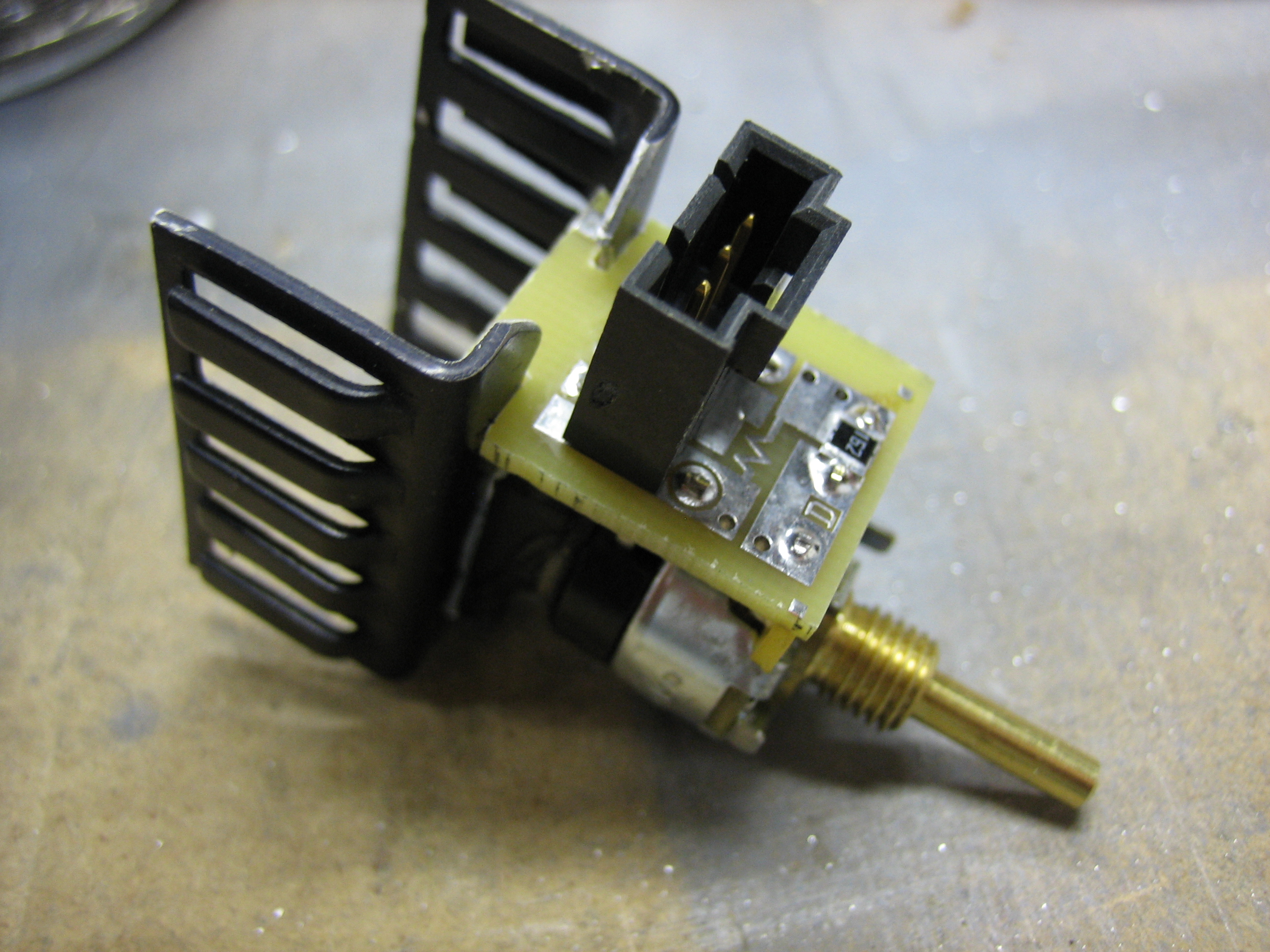
The zig-zag trace that connects the outer two pads regulates the minimum voltage. With this short, the dimmer puts out 1.3V at the low end. This is too low for the annunciator and cabin lights I’m using.
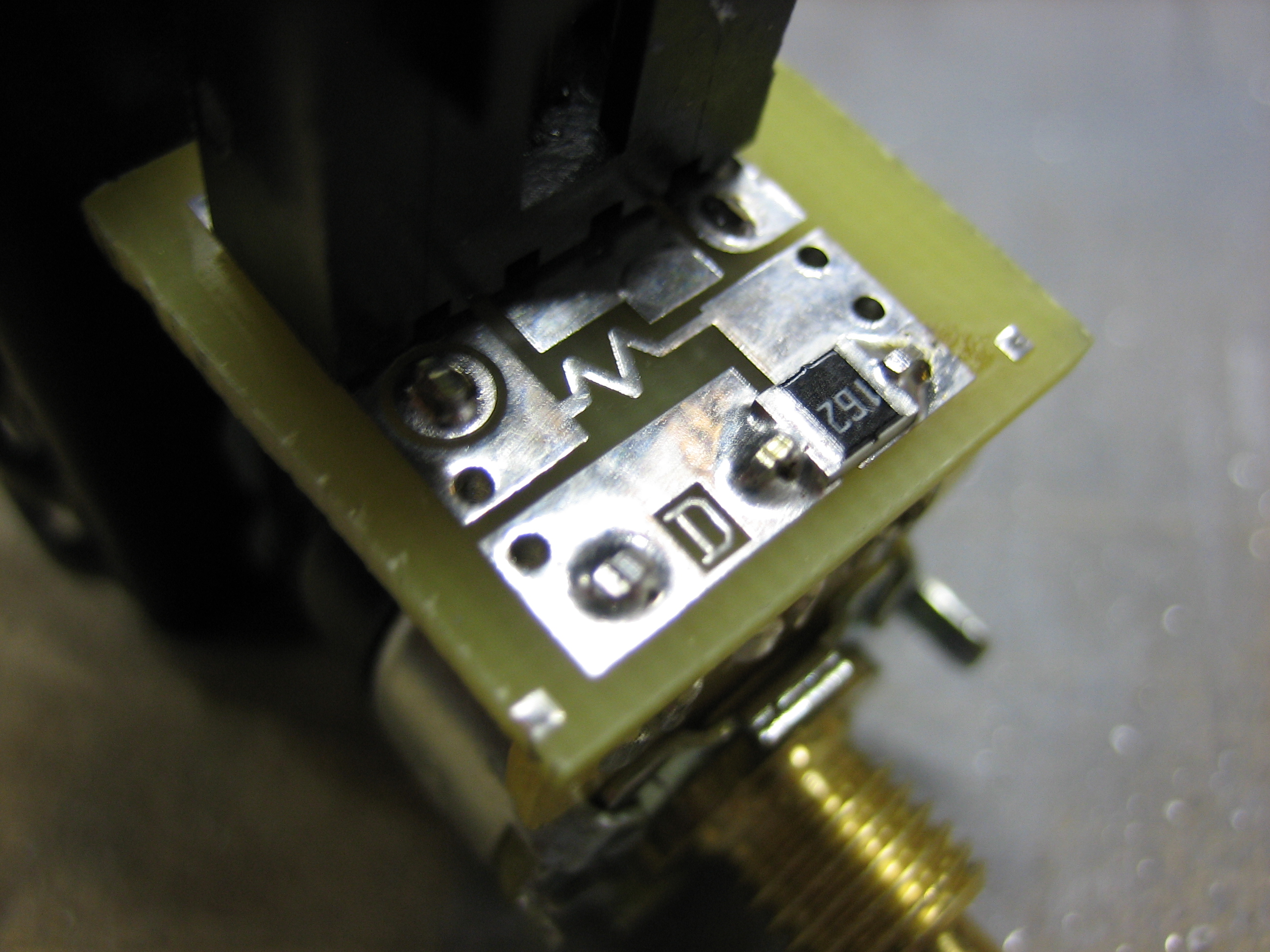
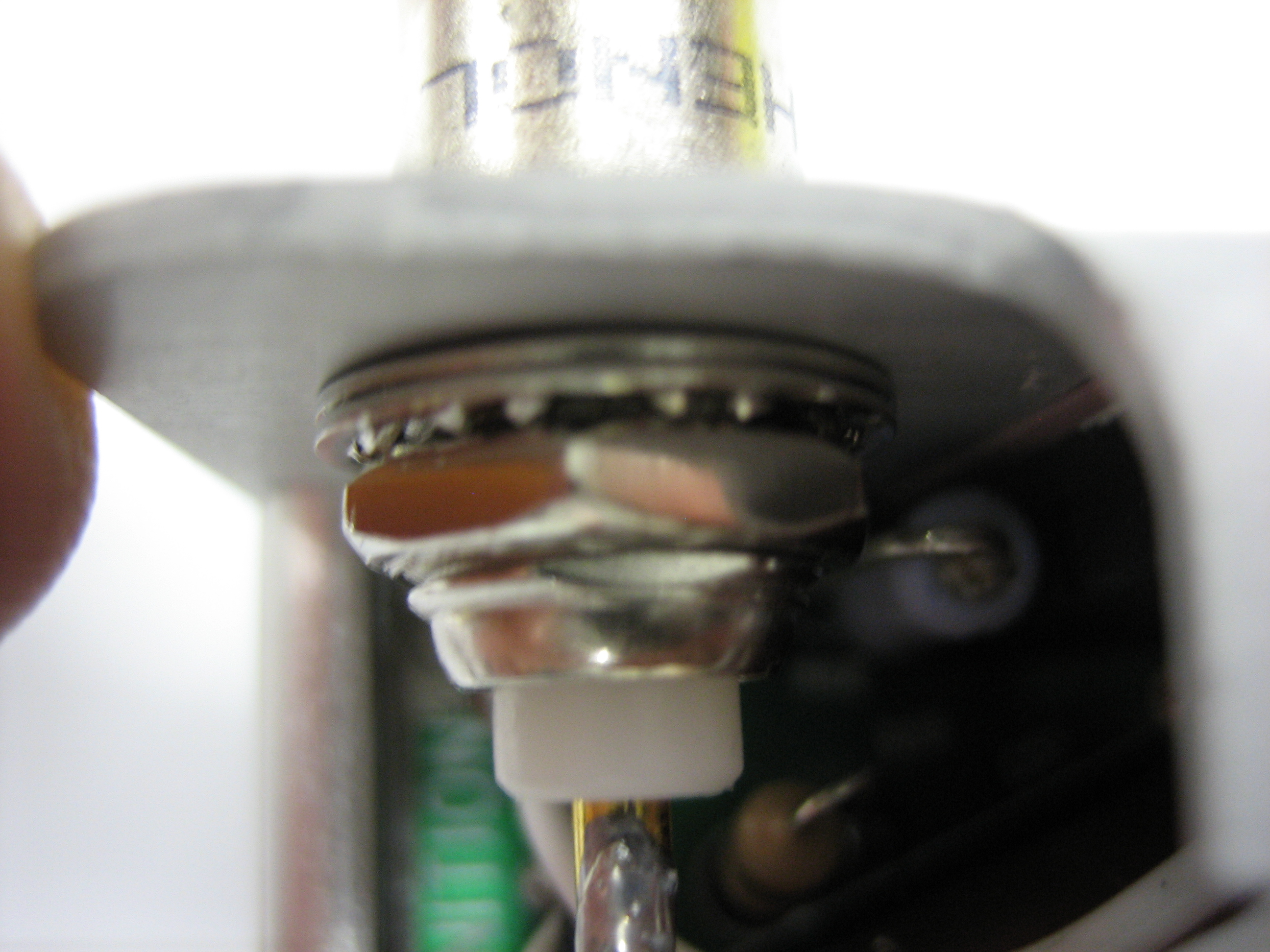
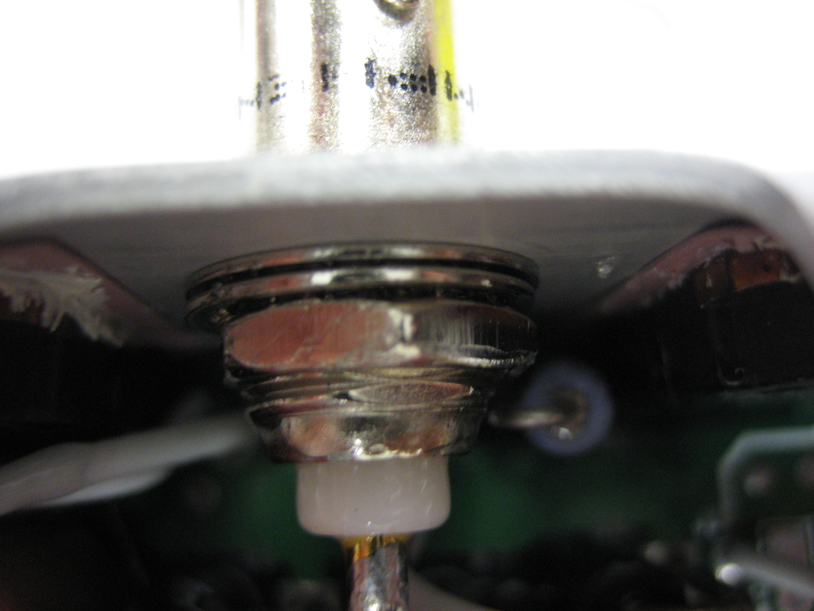
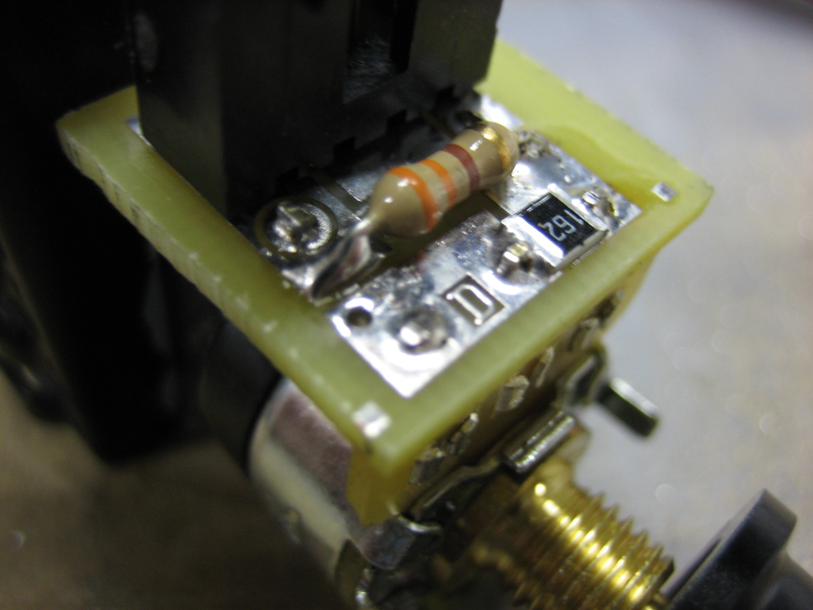
I broke this connection so that I could solder a more appropriate resistor in place of this trace.

The cabin light needs a 330Ω resistor to set the low end of the voltage range to 5V. Below that, the cabin light I’m using shuts off, so there’s no point in letting the dimmer go below that voltage.
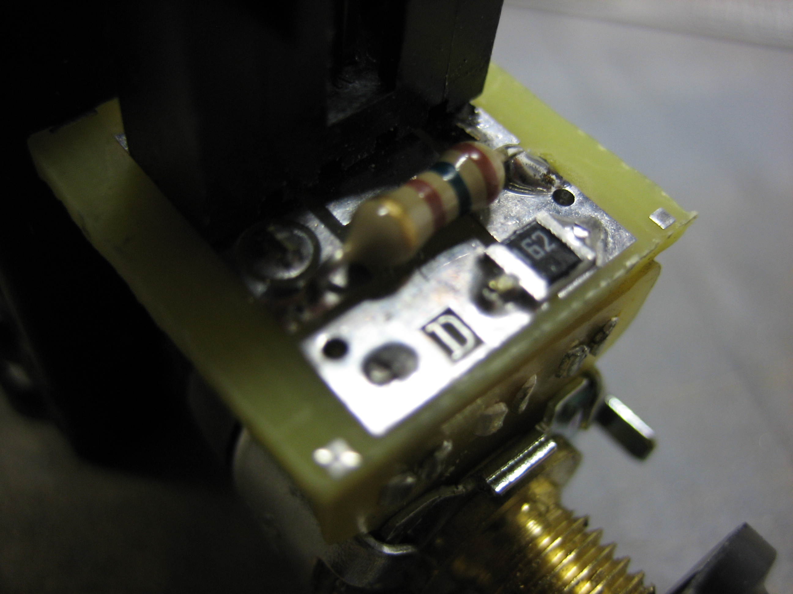
The dimmer that controls the annunciator lights needs a 150Ω resistor to set the low end of the voltage range to 3V. The third dimmer will be used to dim the lights that go under the glareshield.
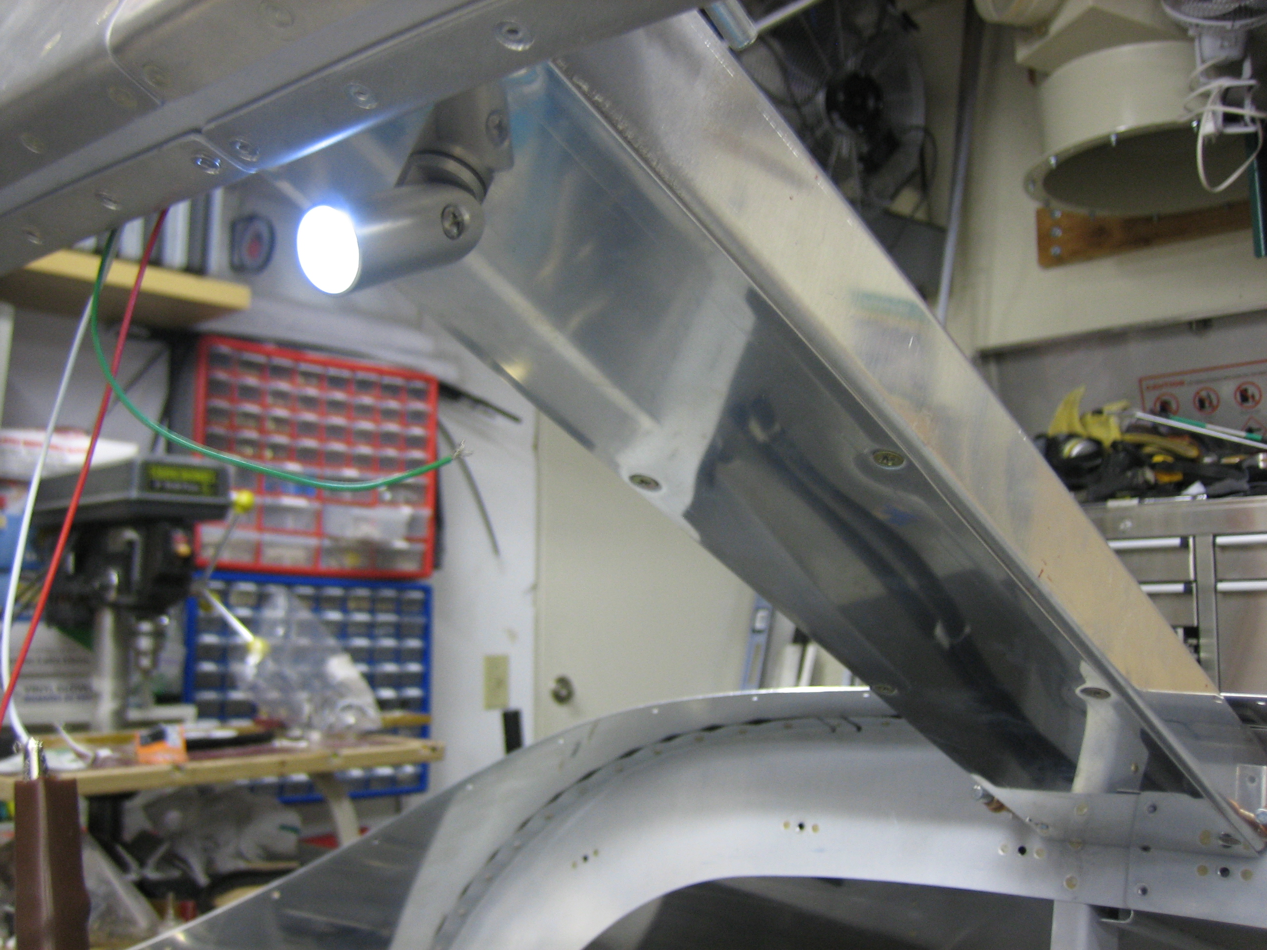
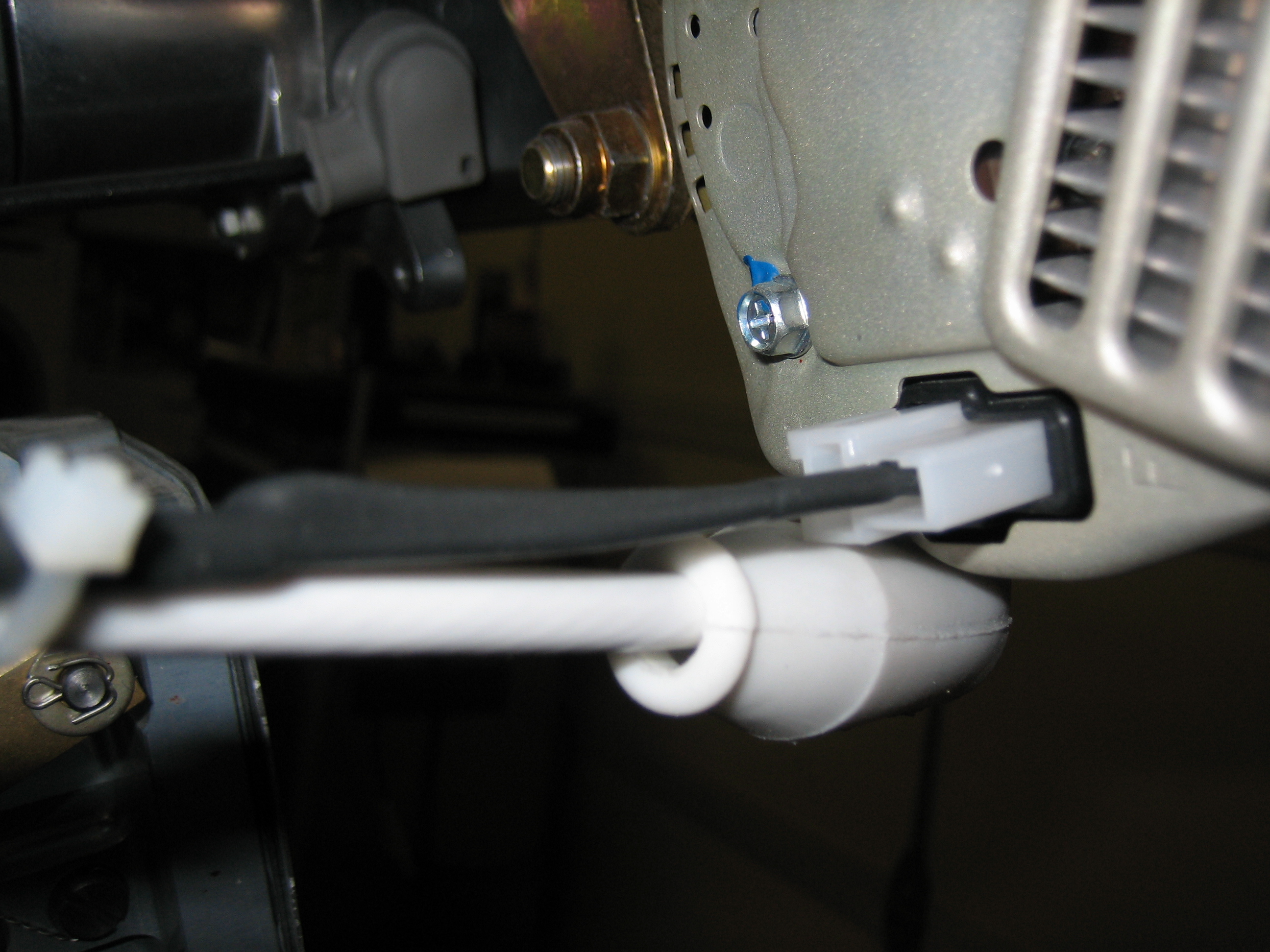
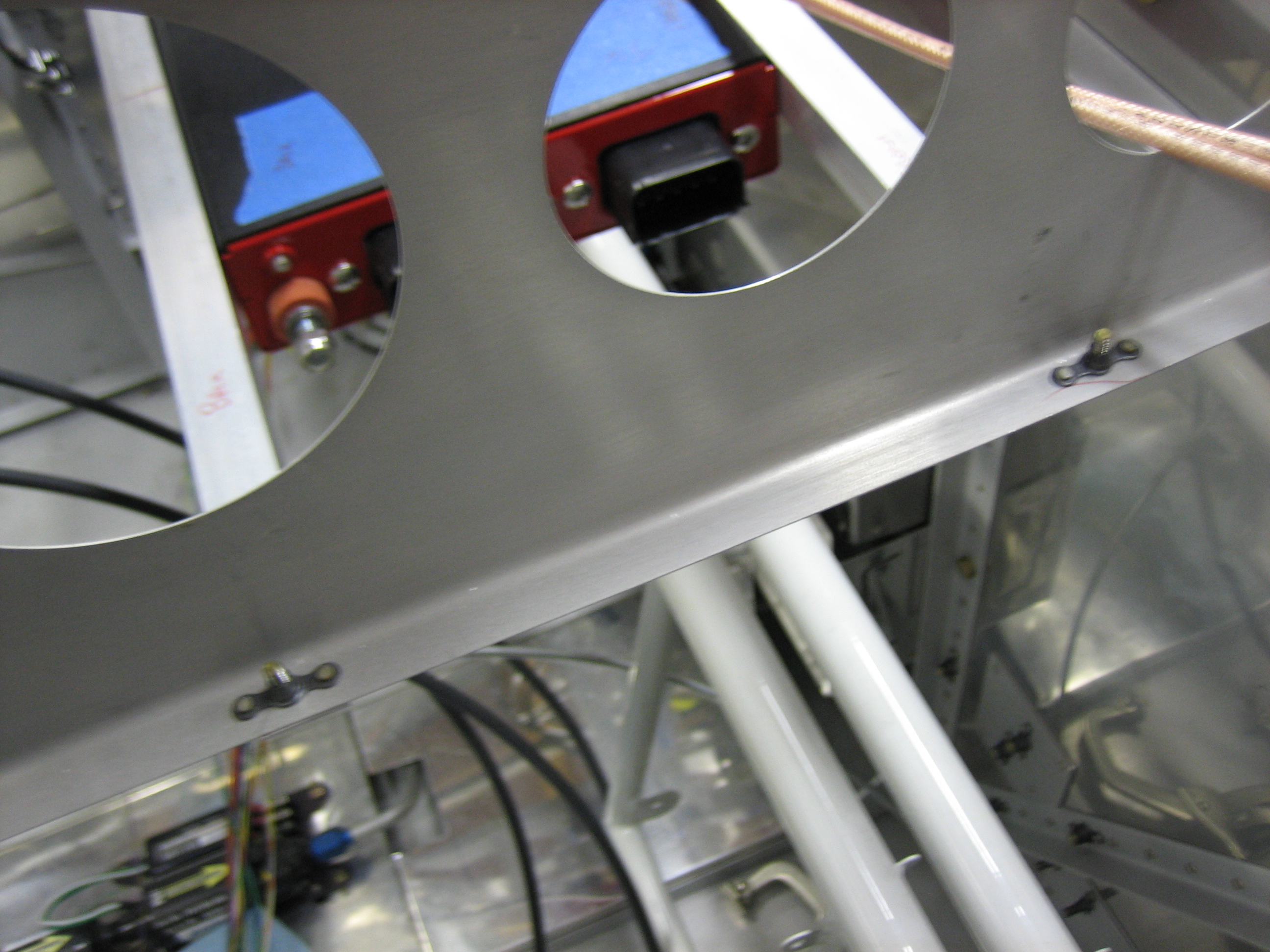
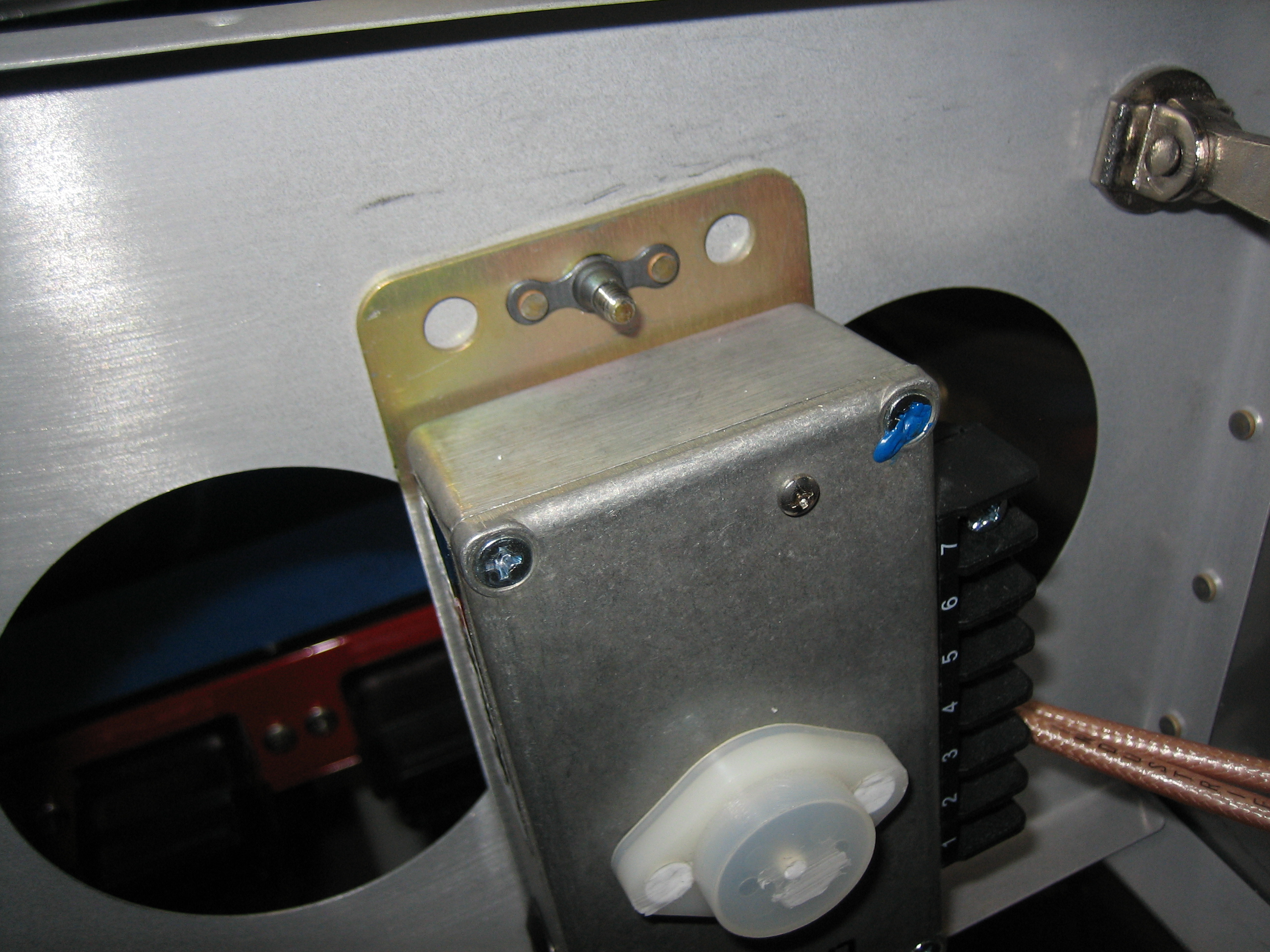
Here’s where I mounted the light. It’s basically as far forward as I could mount it without interfering with the roll bar. This is still low enough that it illuminates the whole panel, but far enough forward that I can illuminate my lap reasonably well. This can also be turned left-to-right as well as angled up and down. I’ll most likely wire this directly to the battery bus so that I can use it to illuminate the cabin and baggage area when loading/unloading the plane.