Painted Canopy Glareshield

In preparation for installing the canopy bubble to the canopy frame permanently, I needed to pain the glareshield a flat black so that there won’t be any glare on the inside of the canopy.  I scuffed the surface with scotchbrite and cleaned it thoroughly since this will be nearly impossible to repaint later.  I then primed it and painted it.

Here’s the finished surface.  Other than a couple of minor boogers, it looks good.

I spent the rest of the night trying to tweak the canopy frame to follow the curve of the fuselage.  The left side was overhanging the side by about 1/16″.  I used my stretcher to stretch the canopy channel and unfortunately, way overshot it.  I tried using the shrinker to pull it back, but ended up breaking the shrinking dies in the process.  I finally had to use my vise and a contraption of parts to bend the frame back into alignment.  It was a major pain in the ass, but it looks pretty good now.

Finally, I pulled the canopy bow off the plane and drilled the splice plate.

Installed New Brake Lines and Bled Brakes

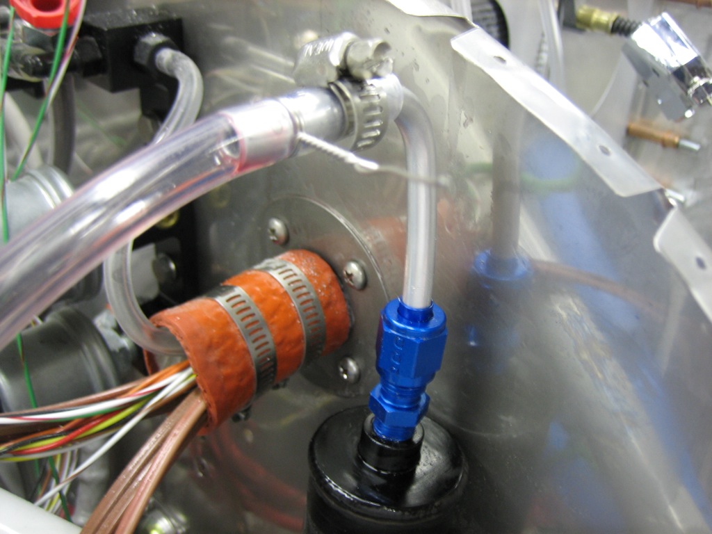
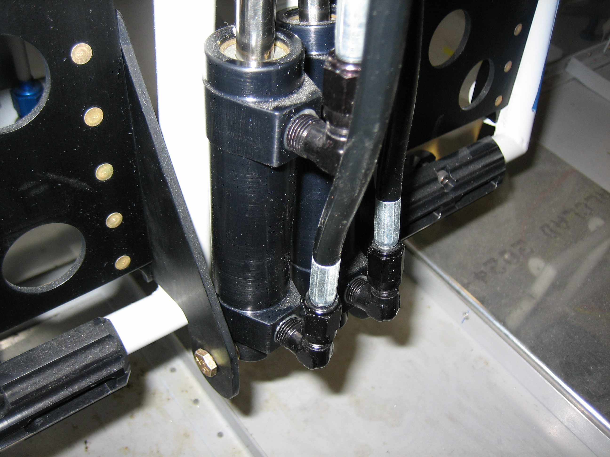
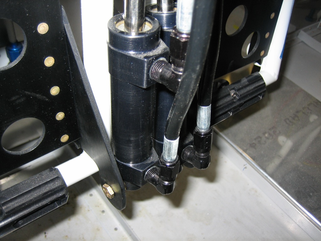
The last time I spoke with Brett at Bonaco, he indicated that they now have black anodized fittings, so I ordered replacement AN822-3D fittings and new hoses from the reservoir to the master cylinder with black fittings on each end.  This looks so much nicer now that everything associated with the brakes and rudder pedals is black anodized aluminum.

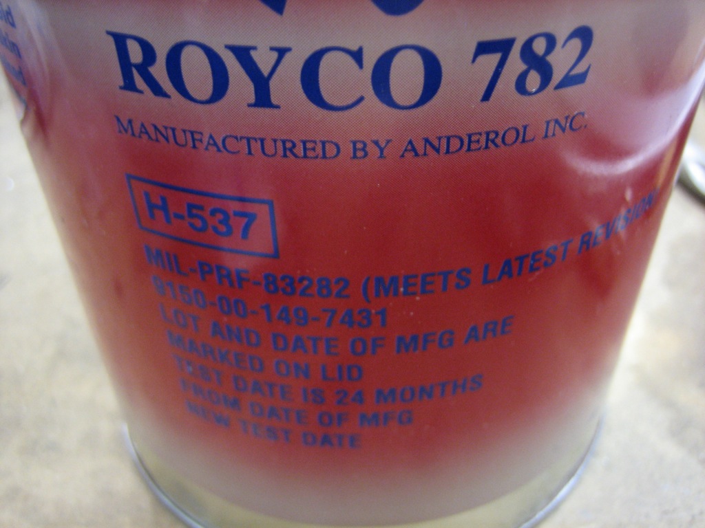
I torqued down all of the fittings and decided to fill the brake system tonight.  I’m using Royco 782 fluid.  I was able to find quart sizes of this at SkyGeek.com.

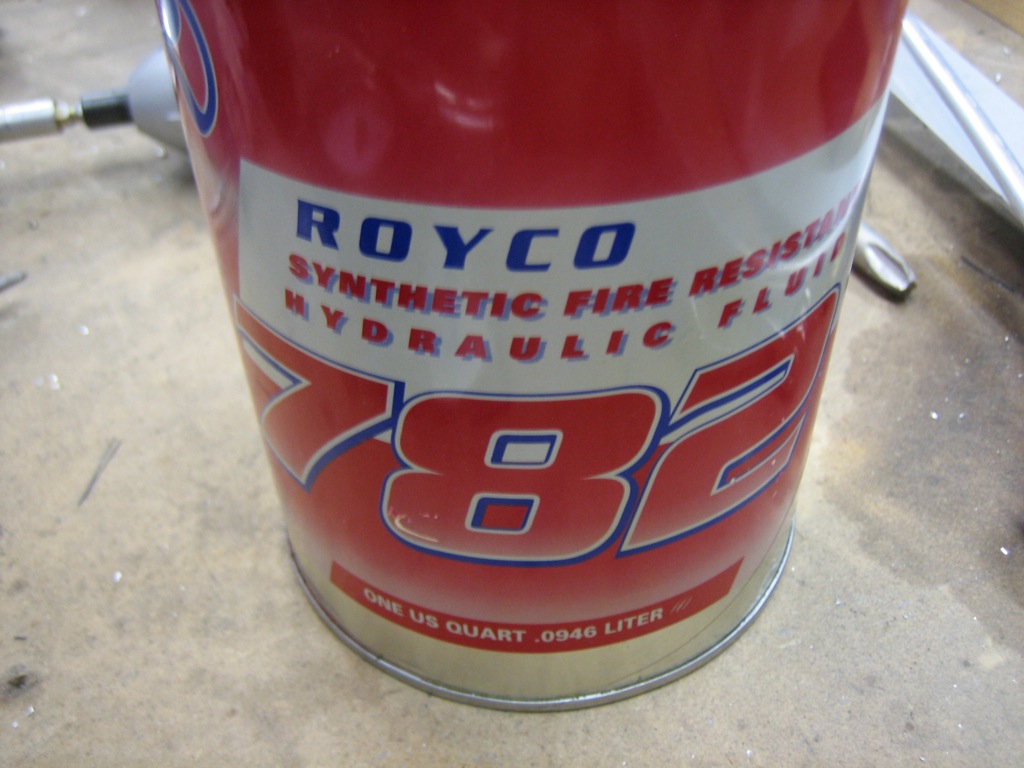
Royco 782 is a MIL-PRF-83282 fluid which is the replacement for MIL-H-5606 and has a much higher flash point.  There have been brake fires with MIL-H-5606, so I didn’t want to use that.

The general consensus seems to be to use a pressure system to fill the brake system from the bottom, but people sometimes still have issues with bubbles in the system.  Getting the bubbles out of the system has nothing to do with the direction you fill the system, it’s all about getting a high flow rate through the system.  If the flow rate is too slow, bubbles will get stuck in high spots in the system since they tend to migrate fairly slowly through the narrow lines.  With a high enough flow rate, the bubbles can’t help but be carried along with the fluid.

Instead, what I did was create a closed system to pump the brake fluid through.  I hooked up a fitting and hose to the brake fluid reservoir and put the other end in the can of brake fluid.  I then hooked up another hose to the fitting on the bottom of the wheel caliper and also put that hose in the can of brake fluid.  Now, as fluid is pumped out of the can and through the system, it’s returned back to the can.  All I had to do after that was operate the brake pedals fully and moderately quickly until nothing but clean fluid was being pumped back into the can.  This only took about 30 seconds on each side.  The brakes are absolutely rock solid and no leaks!

Riveted Canopy Bow and Installed Canopy

I primed and riveted the canopy bow together.  One of the rivets intersects a tooling hole, but I’ll fill both of these with filler anyway.

I clecoed on the canopy bow and then drilled the latch lugs to the canopy frame.  There is very little room to fit these, so Van’s basically has you just guess where to drill the holes and then cheat them over if you guess wrong.  I didn’t like that approach, so I slipped the lugs in from the bottom and then engaged the latch to define the lug position.  I then ran the drill bit through one of the holes in the weldment to mark the lug.  I then removed it and center punched along the scratch and drilled to #40.  I reinstalled the lug, held it vertical and drilled the second hole.  This worked perfectly and the lugs seem to be in just the right spot.  Finally, I reinstalled the struts and raised the full canopy frame for the first time.  Without the canopy, the struts nearly eject the canopy frame from the airframe.

I temporarily installed the canopy to see how it affected opening.  With the extra weight of the canopy, it opens nice and smooth.  You really have to manage it coming down though since it hits the neutral point about 12-18″ up and will slam down if you’re not careful.  I’m also going to have to add some guides that help align the lugs with the holes in the side rails.  Without that, it’s too easy to have the canopy come down slightly cocked and have the lugs hit the top of the side rails.

Finally, I spent about an hour inside the cockpit.  I put down enough padding to simulate the thickness of the seats to see how much head and knee room I was going to have.  I also tried the control bracket to see how it affects my knee room.  I ended up biasing it to the right so that the prop control is centered on the panel.  This will give the passenger less knee room, but they’re not flying so it shouldn’t be that big of a deal.  I also spent a bunch of time thinking about the placement of switches, buttons, etc. on the panel.  The radio stack will be centered with the SkyView displays as close to the stack as I can mount them.  This should leave room on the left for a TruTrak Gemini and some switches.  There will also be some switches below the SkyView displays and a few other odds and ends on the right side of the panel.  I’ll lay this out more precisely eventually.

Fit Flap Position Sensor

I stopped by the hobby shop tonight and picked up some small 4-40 threaded rod and some threaded clevis ends to connect the flap arm to the Ray Allen position sensor that will feed the flap position to the VP-X.  I stole the dimensions from Mike Bullock’s site and they worked perfectly.

I fabricated a small clip that bolts to the adel clamp to connect the clevis to the flap rod.  I used a piece of 0.063″ angle with one leg mostly cut off.  This wraps around the side of the adel clamp flange and will prevent it from rotating.

Here’s the other end.  I didn’t tighten the nut fully since it interferes with the nut on the clevis.

I turned the screw around on the clevis and tightened it more fully.  I ended up also having to use one of these tiny lock nuts to provide clearance from the clevis screw.

Replaced SkyView USB Cable and Worked on Control Stick Grips

The SkyView DB37 connector comes with a long USB cable with a type A female end on it.  The other end connects to pins 16-19 on the DB37 connector.  This cable is kind of useless as the female end can’t be mounted to anything.

I extracted these pins from the DB37 connector so I can replace it with a more appropriate connector.

I picked up this 18″ USB 2.0 A M/F panel mount cable.  I could have just connected this to the preinstalled SkyView USB cable, but it won’t have been extremely long and would have just ended up coiled up behind the panel.  I clipped off the male end and crimped on some d-sub sockets.

I then reassembled the connector.  I really wish Dynon had just installed this sort of cable in the first place.

Here you can see that the cable is long enough to reach anywhere near the SkyView screen.  To confirm everything was working correctly, I upgraded the SkyView to 2.6 using the USB thumb drive plugged into this cable.  I’ll install an identical cable on the other SkyView screen once I order it.

While I had my electrical tools out, I went ahead and soldered some lead wires to the controls that will be installed in the control stick grips.

Before I can install the controls into the stick for good, I wanted to put a couple of coats of tung oil on the grips.

Installed Switches/Buttons in Controls Sticks

After soldering all the wires to the control stick switches, I slipped some expandable sleeving and finished the end with heat shrink.  This is the copilot’s PTT button.

The copilot’s stick is removable, so the PTT switch needs a connector in it at the joint in the stick.  I’m using a small 0.062″ 2 circuit plug.  The wire will exit between the rod ends at the bottom of the stick.  I added a layer of heat shrink around the sleeving where it passes between the rod ends to provide an extra measure of abrasion resistance.

I drilled both control stick grips and epoxied in some small 8-32 t-nuts.

I then installed some 1/4″ long socket head set screws that will be used to anchor the grips to the sticks.

With all of the wire soldered on the switches and buttons, I installed them in the grips.

I slipped some sleeving over the nine wires coming out of the pilot’s grip and then installed it on the pilot stick.  Just like on the copilot’s side, I routed the wires out through the bottom of the stick.  Many builders drill a hole in the side of the stick near the pivot point to avoid routing the wires near the moving parts, but Van’s recommends against this as it will weaken the stick.

Just like on the copilot’s side, I installed a length of heat shrink where the wire bundle passes between the rod end bearings.

Designed Annunciator Light Controller Circuit

I’m planning on having 7 or 8 annunciator lights.  Some will be triggered when a signal is pulled to ground and others when a signal is pulled to 12V.  I also wanted a button to test all of the lights and a dimmer so I can reduce the brightness for night flight.  I couldn’t find an off the shelf controller that I liked, so I decided to dust off the old EE degree and design a simple circuit that did what I want.  I prototyped a two light version of the circuit below.  You can sort of see the two lights (red and yellow) near the top center of the picture.  The left switch at the bottom simulates the push-to-test button.  When thrown, both lights should light up.  The right switch simulates one of the circuits that should light an annunciator light when pulled to ground.  This circuit doesn’t handle signals pulled to high because I didn’t have any diodes on hand to do that portion of the circuit.

Here’s the push-to-test switch thrown.  You can see both lights are on.

Here’s the single signal light illuminated.  The lights only require 20mA at 12V, so a simple 2N2222A TO-92 NPN transistor can handle this without even warming up.  The end circuit only needs one diode, one resistor, and one transistor per light.  There’s one additional resistor in the circuit to handle one edge case that could blow a diode if one of the high signal pins were pulled to ground accidentally.

Refined Annunciator Control Circuit

I’ve spent the last couple of days refining the annunciator light circuit and laying out a PCB that I’m going to have fabricated by expresspcb.com.  They require a minimum order of three boards, so I’ll have a couple of extra if anyone wants to buy them.  Email me at the address in the left bar if you want one.

I also designed a couple of other simple PCBs to replace the SkyView splitters as well as the interconnect between the SkyView and the other avionics.  I’ll post pictures of the boards when I get them.

Unfortunately, the PCB design software only runs on Windows and is really shitty.  I haven’t had to use Windows this much in almost 10 years, but it was just as bad as I remember.