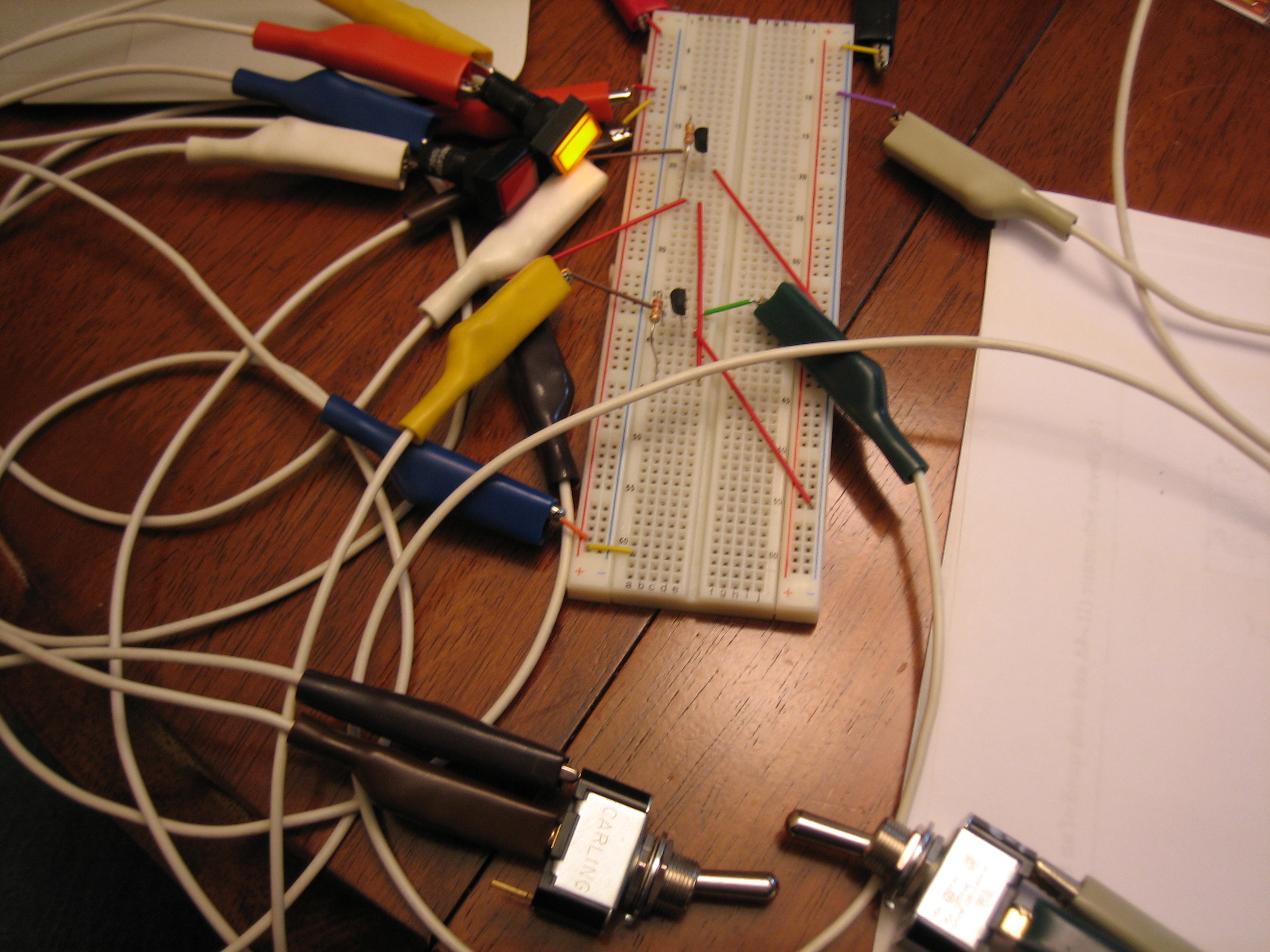
I’m planning on having 7 or 8 annunciator lights. Some will be triggered when a signal is pulled to ground and others when a signal is pulled to 12V. I also wanted a button to test all of the lights and a dimmer so I can reduce the brightness for night flight. I couldn’t find an off the shelf controller that I liked, so I decided to dust off the old EE degree and design a simple circuit that did what I want. I prototyped a two light version of the circuit below. You can sort of see the two lights (red and yellow) near the top center of the picture. The left switch at the bottom simulates the push-to-test button. When thrown, both lights should light up. The right switch simulates one of the circuits that should light an annunciator light when pulled to ground. This circuit doesn’t handle signals pulled to high because I didn’t have any diodes on hand to do that portion of the circuit.
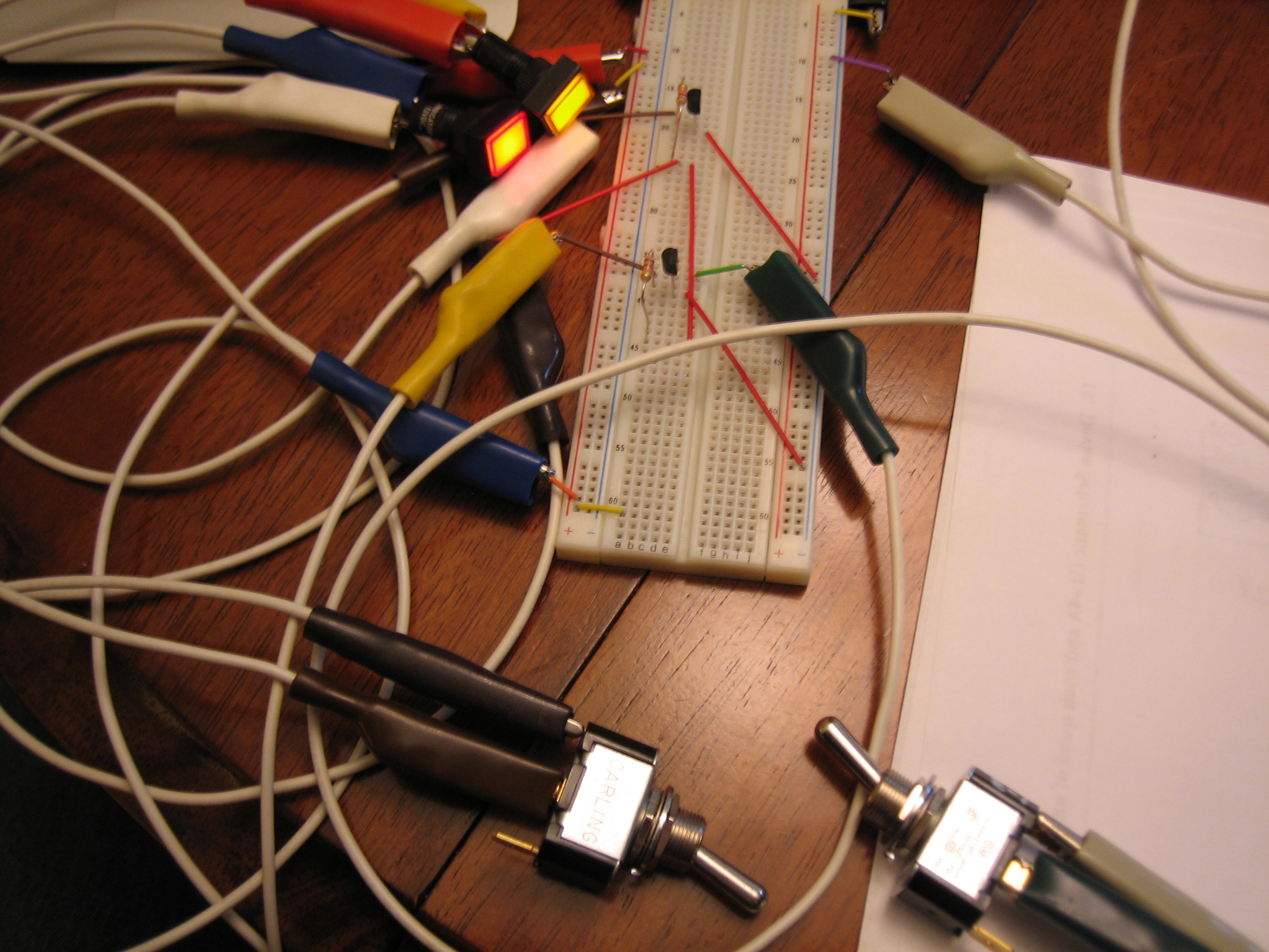
Here’s the push-to-test switch thrown. You can see both lights are on.
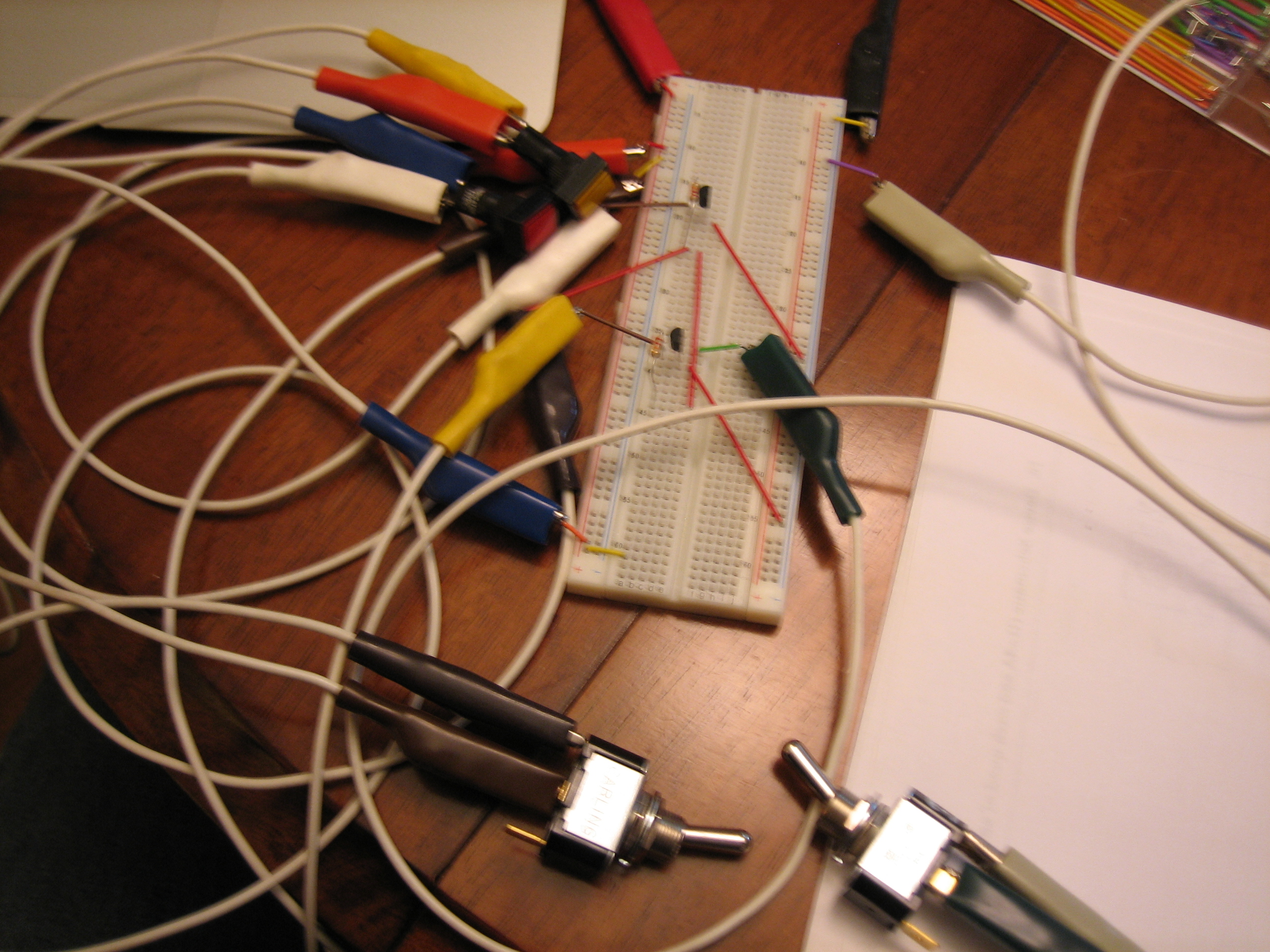
Here’s the single signal light illuminated. The lights only require 20mA at 12V, so a simple 2N2222A TO-92 NPN transistor can handle this without even warming up. The end circuit only needs one diode, one resistor, and one transistor per light. There’s one additional resistor in the circuit to handle one edge case that could blow a diode if one of the high signal pins were pulled to ground accidentally.