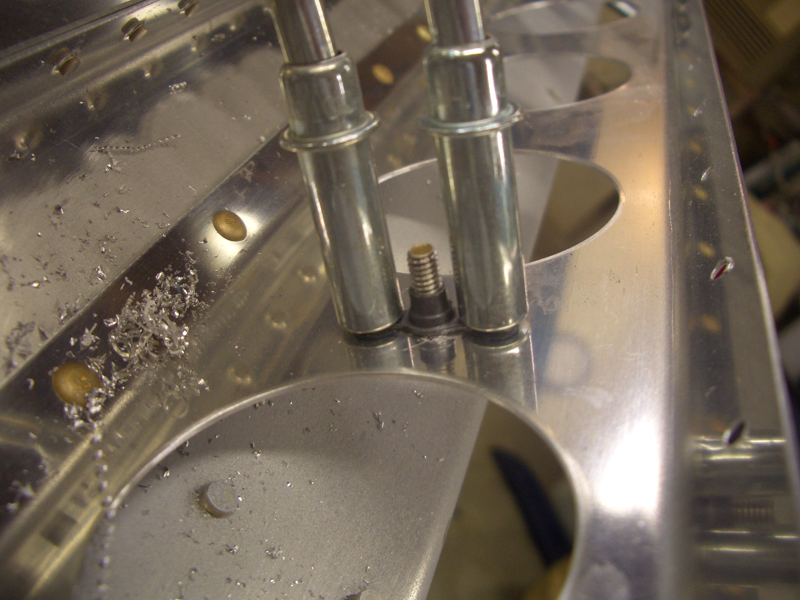
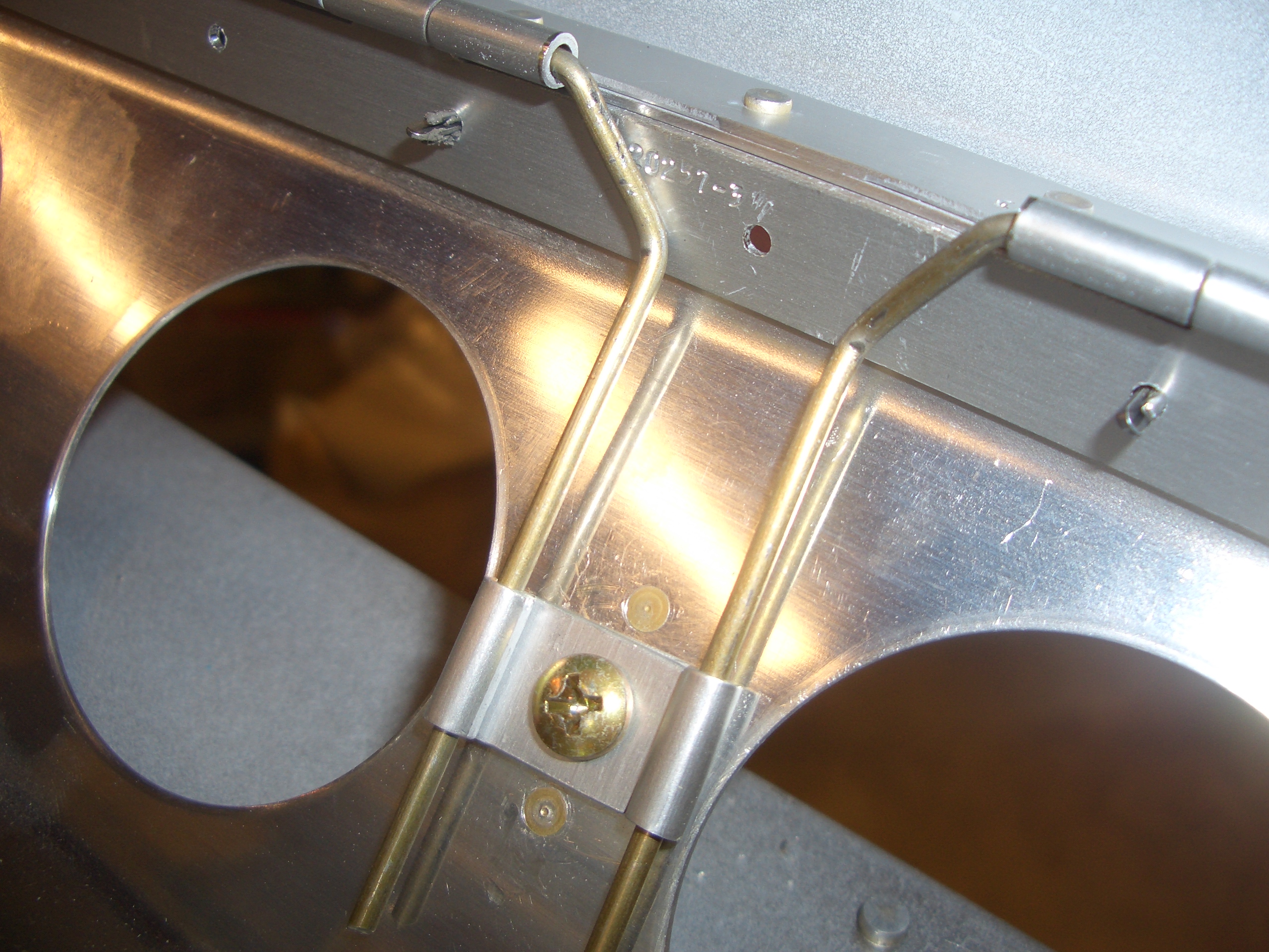
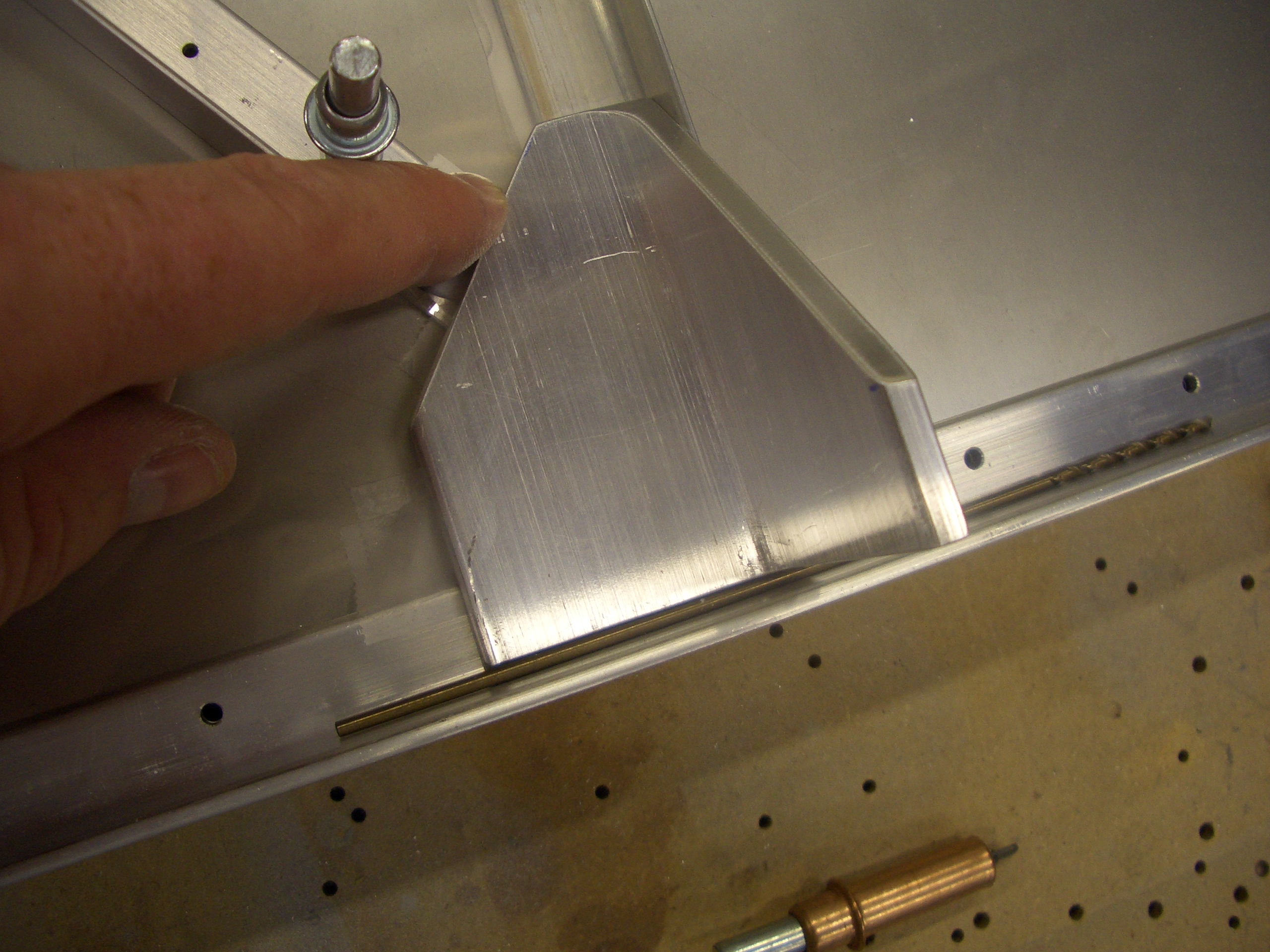
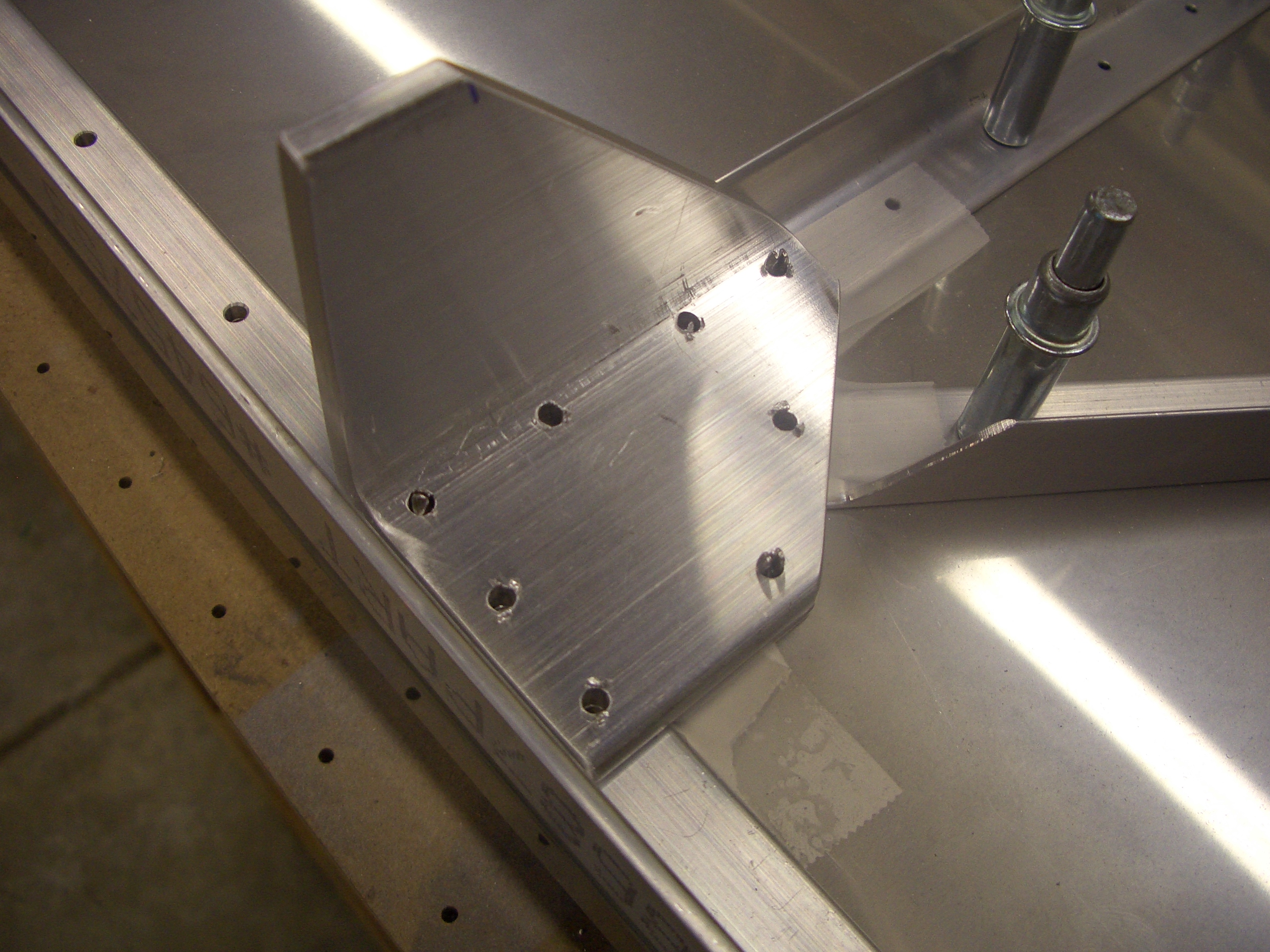
The first step in rigging the ailerons is to place the aileron alignment bracket over the bellcrank with a bolt through it and the rear aileron push tube’s end bearing.
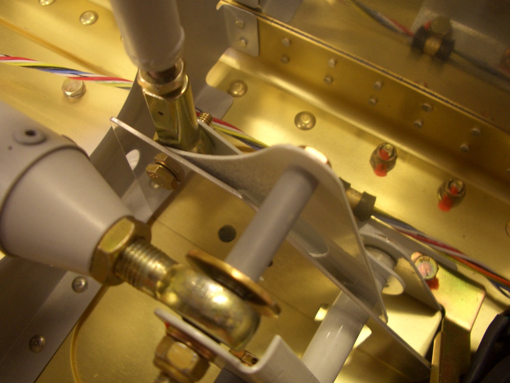
Next is to adjust the length of the rear pushrod until the trailing edge of the aileron lines up with two tooling holes in the main wing rib. I placed a couple of AN3 bolts through these holes and then put the straight edge against both sides of the bolts until the trailing edge was centered between them. I loosened the rear aileron push tube end bearings evenly so that I will have the same amount of threads showing at each end.

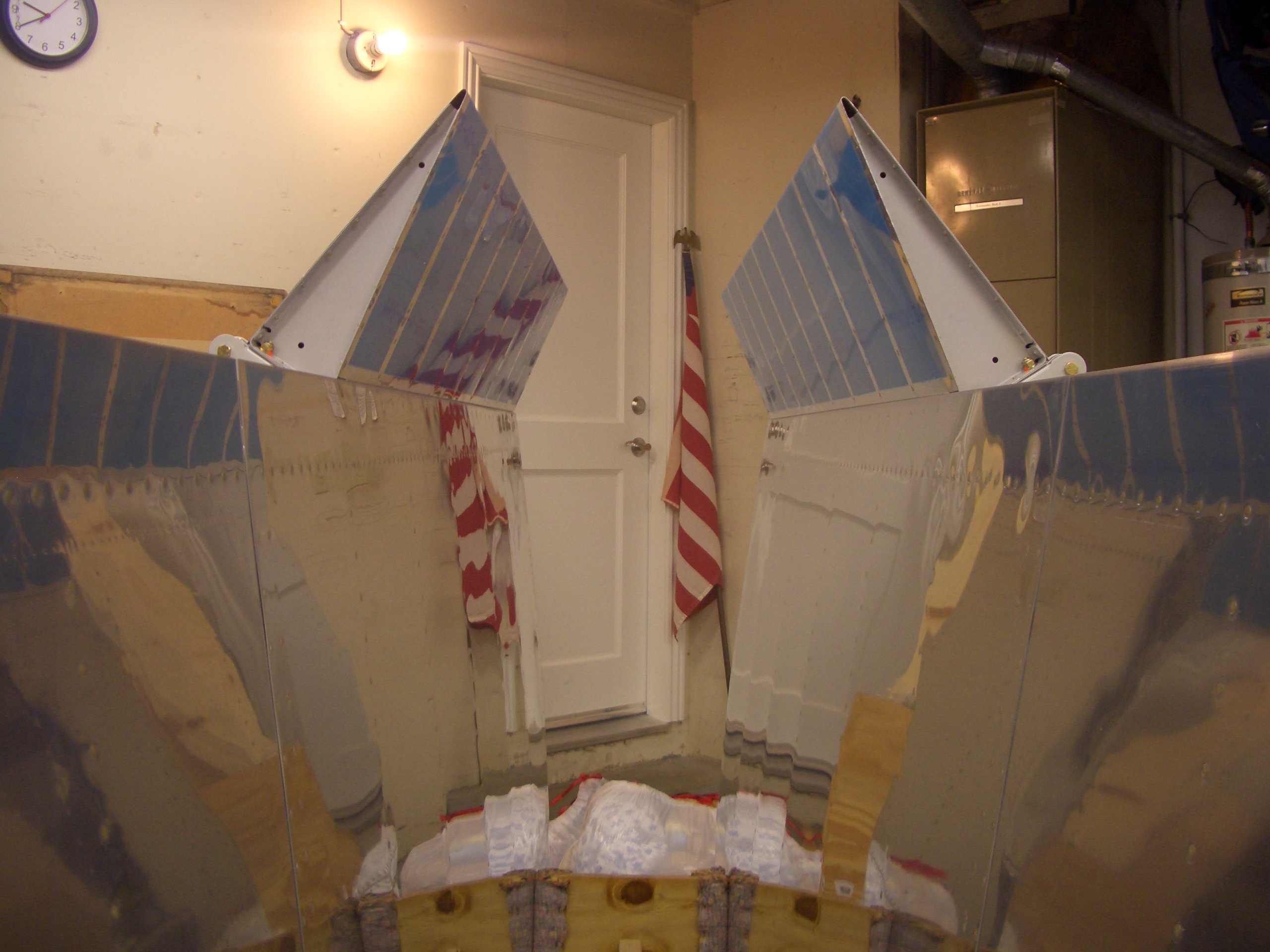
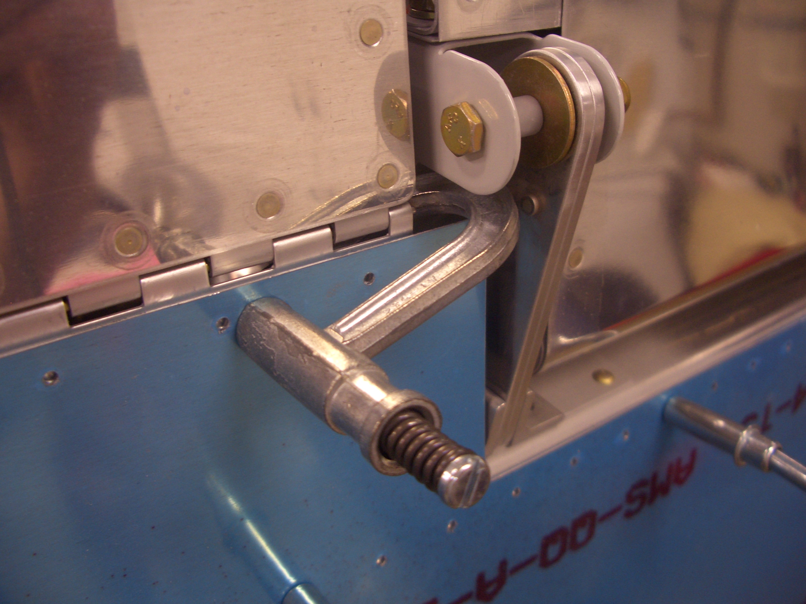
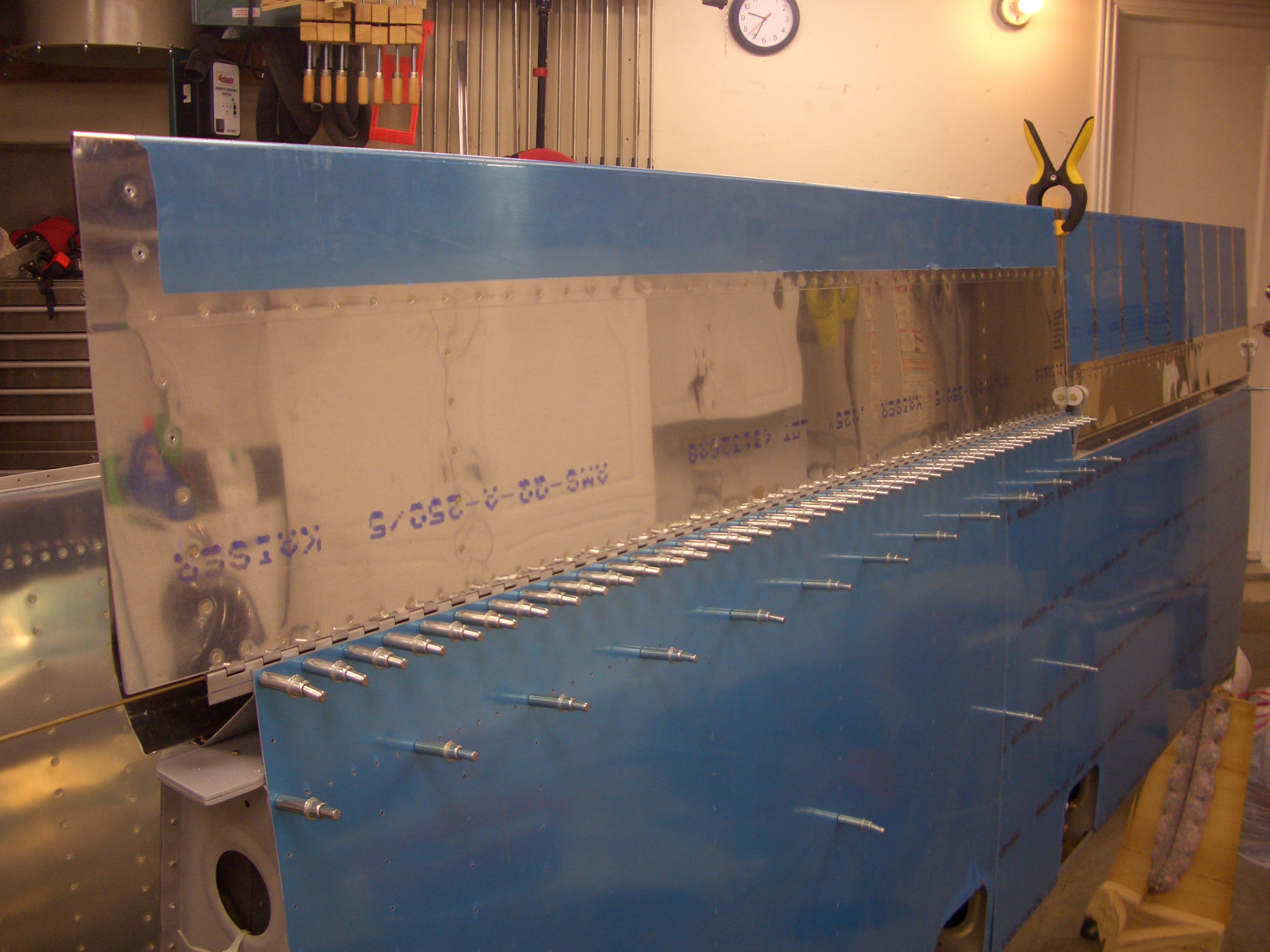
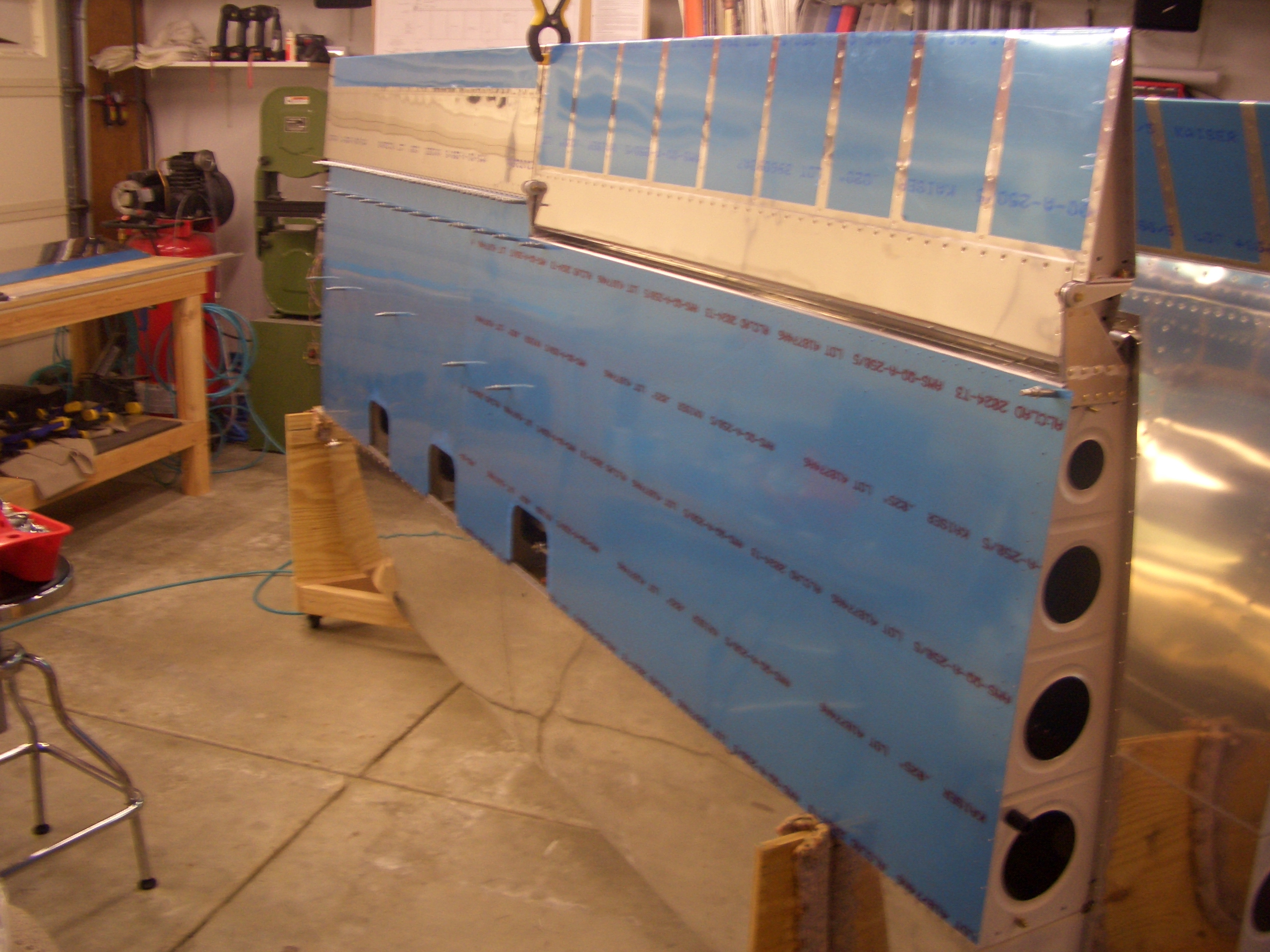
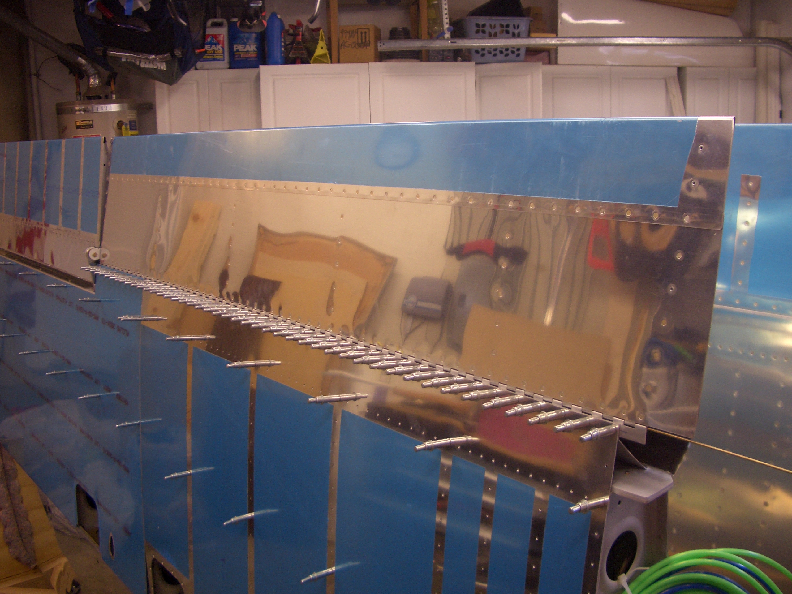
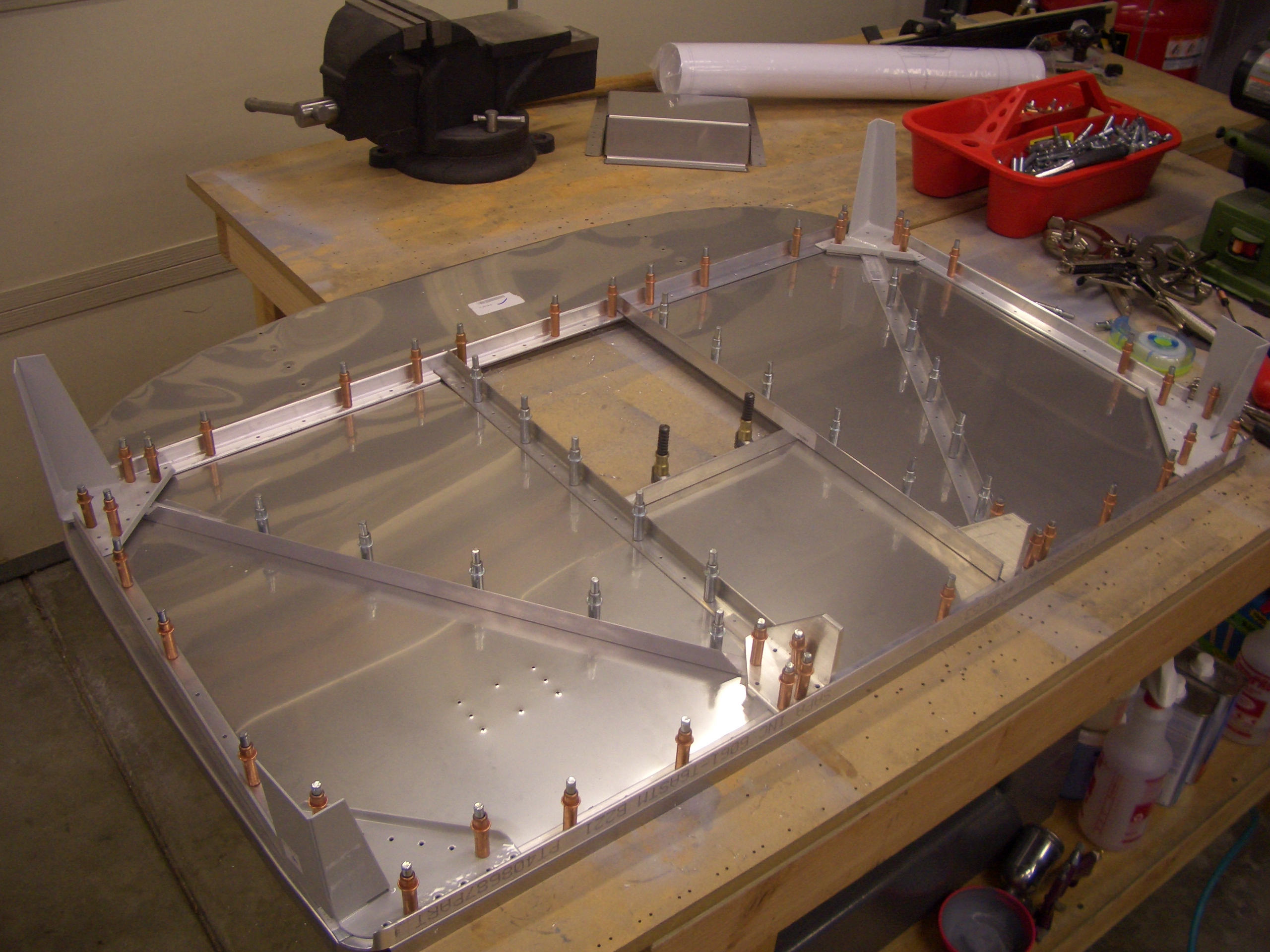
Next up, I clecoed on the bottom skins and put the right flap in place. I spent awhile adjusting the position of the end clamps to get the trailing edges in perfect alignment.

I think I said it before, but these clamps have come in super handy. I would highly recommend getting some if you’re building.

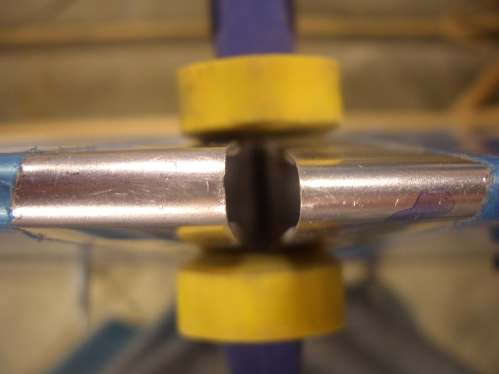
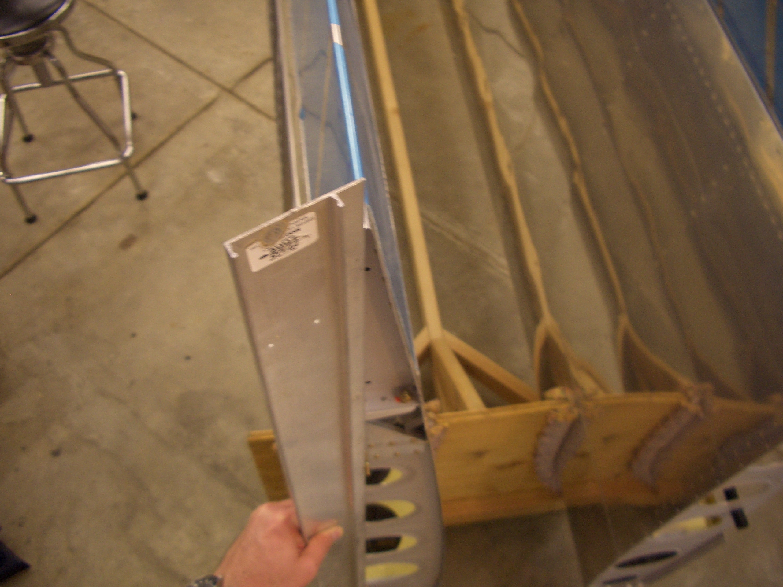
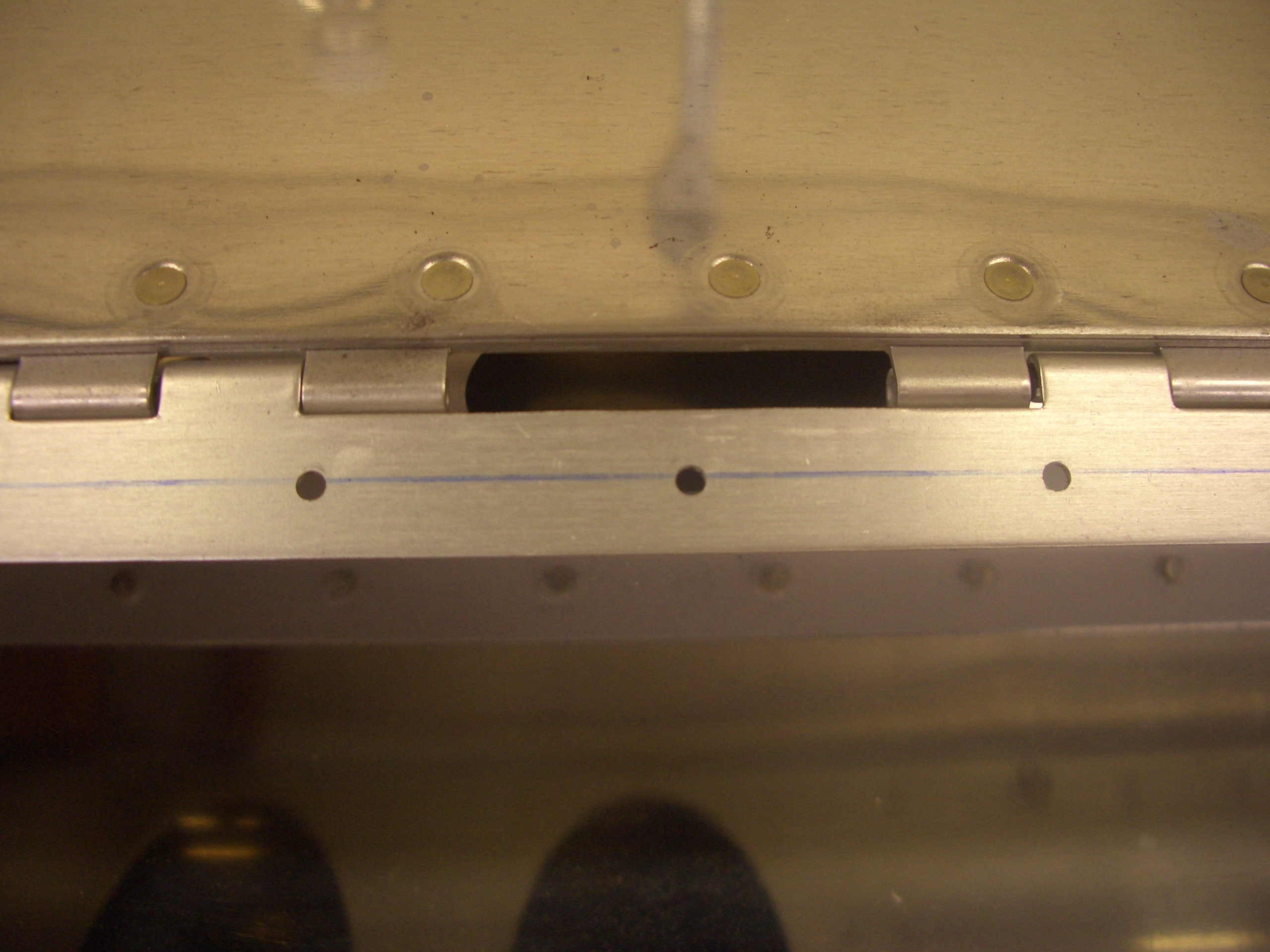
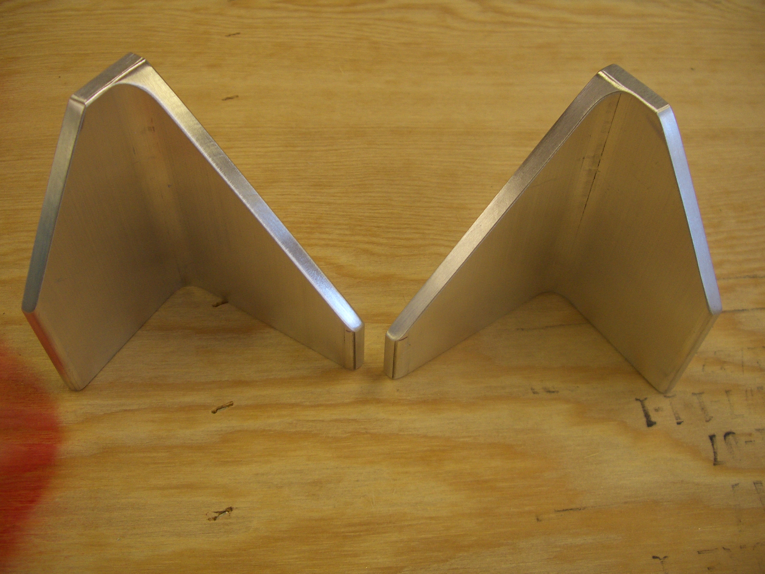
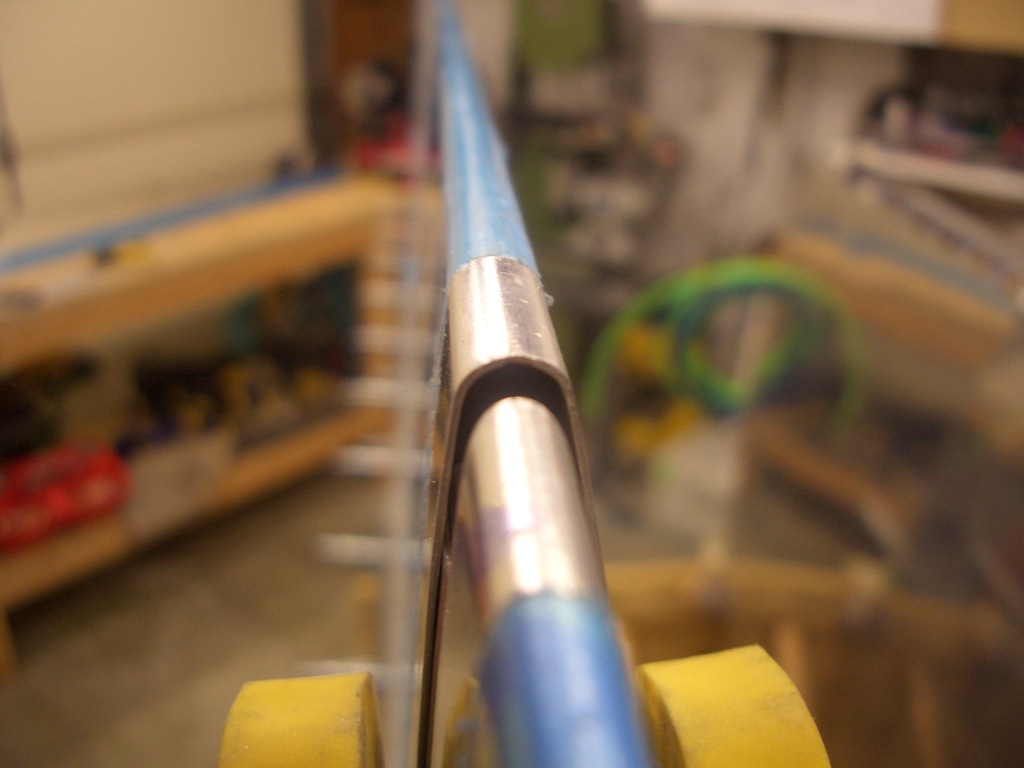
As I was aligning the trailing edges, I noticed something funny. The trailing edge radiuses of the flaps and ailerons are not the same. Here is one shot looking along the edge. The aileron is the lower trailing edge with the smaller radius and the flap is the upper trailing edge with the larger radius.
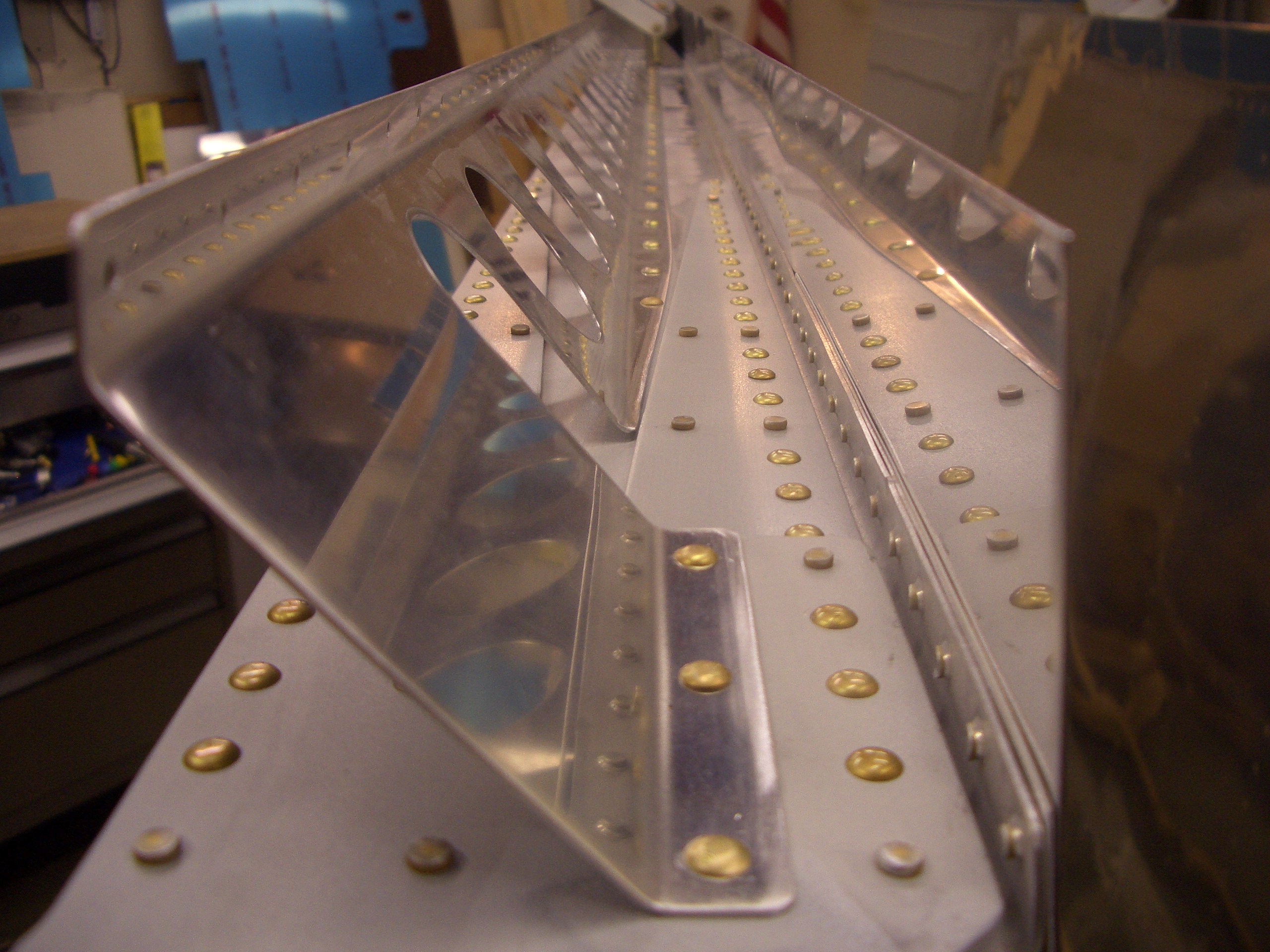
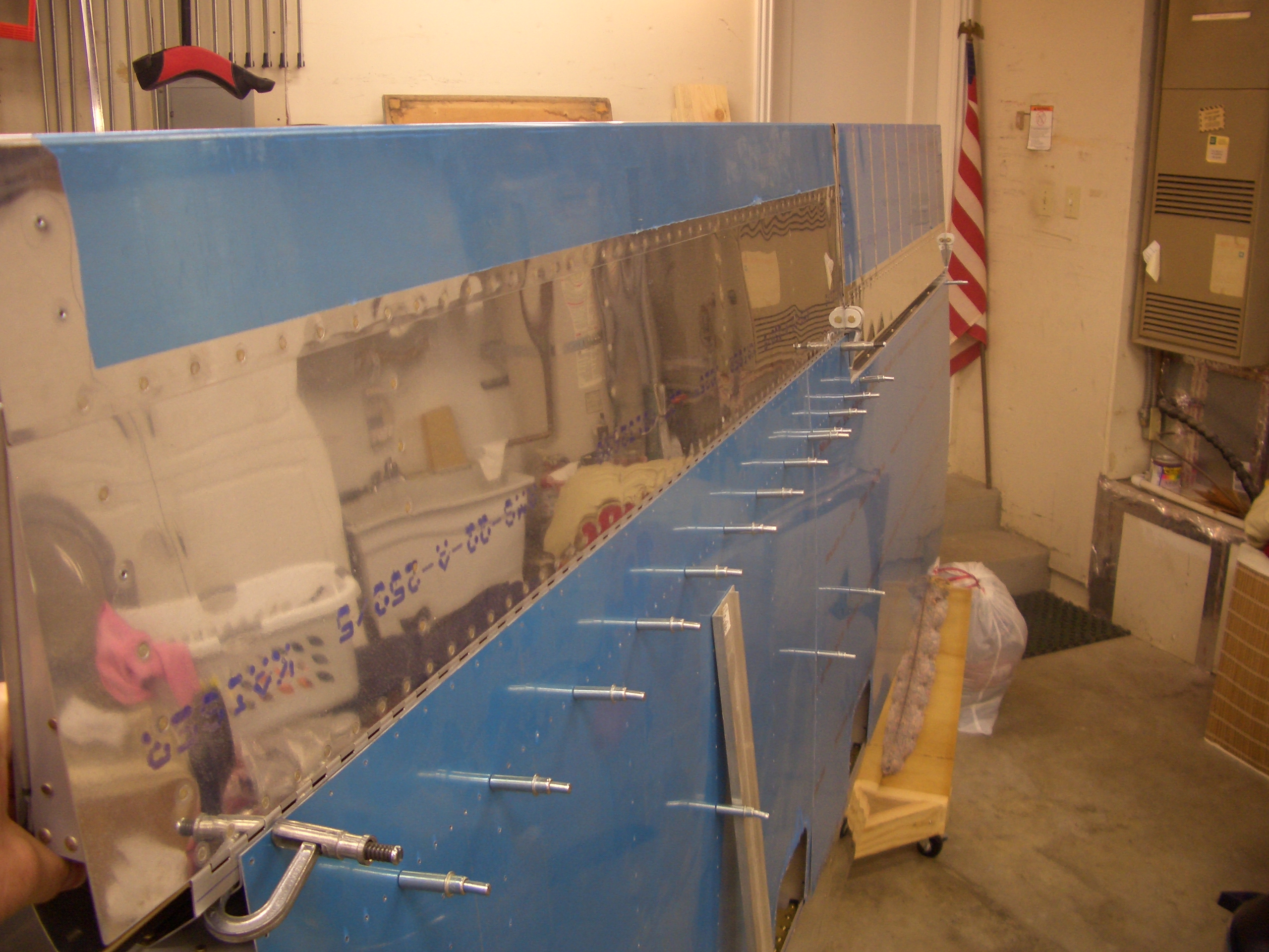
Here is a shot looking down on the trailing edges. The problem is that with the trailing edges aligned front to back, the skin surfaces no longer align. If I make the top skin surfaces flush, then the flap skin on the bottom of the wing will be proud of the aileron bottom skin.
I don’t think I can just squeeze the flap trailing edge either since the flap skins nicely follow the angle defined by the end ribs. If I squeeze the trailing edge, the skin will have to bend inward as it crosses the trailing edge of the end ribs. I’m going to see if anyone on vansairforce.net has any ideas.
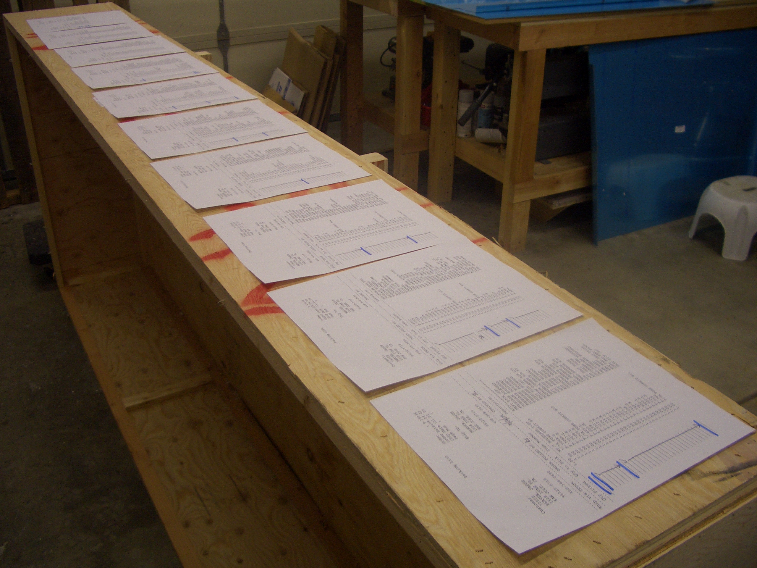
Update: It turns out that the scale drawings on the flap and aileron plan pages clearly show that the flaps and ailerons have different trailing edge radii, so I’m not going to do anything about this.