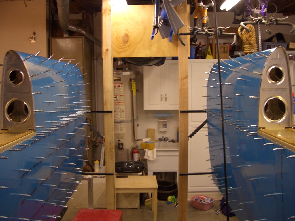
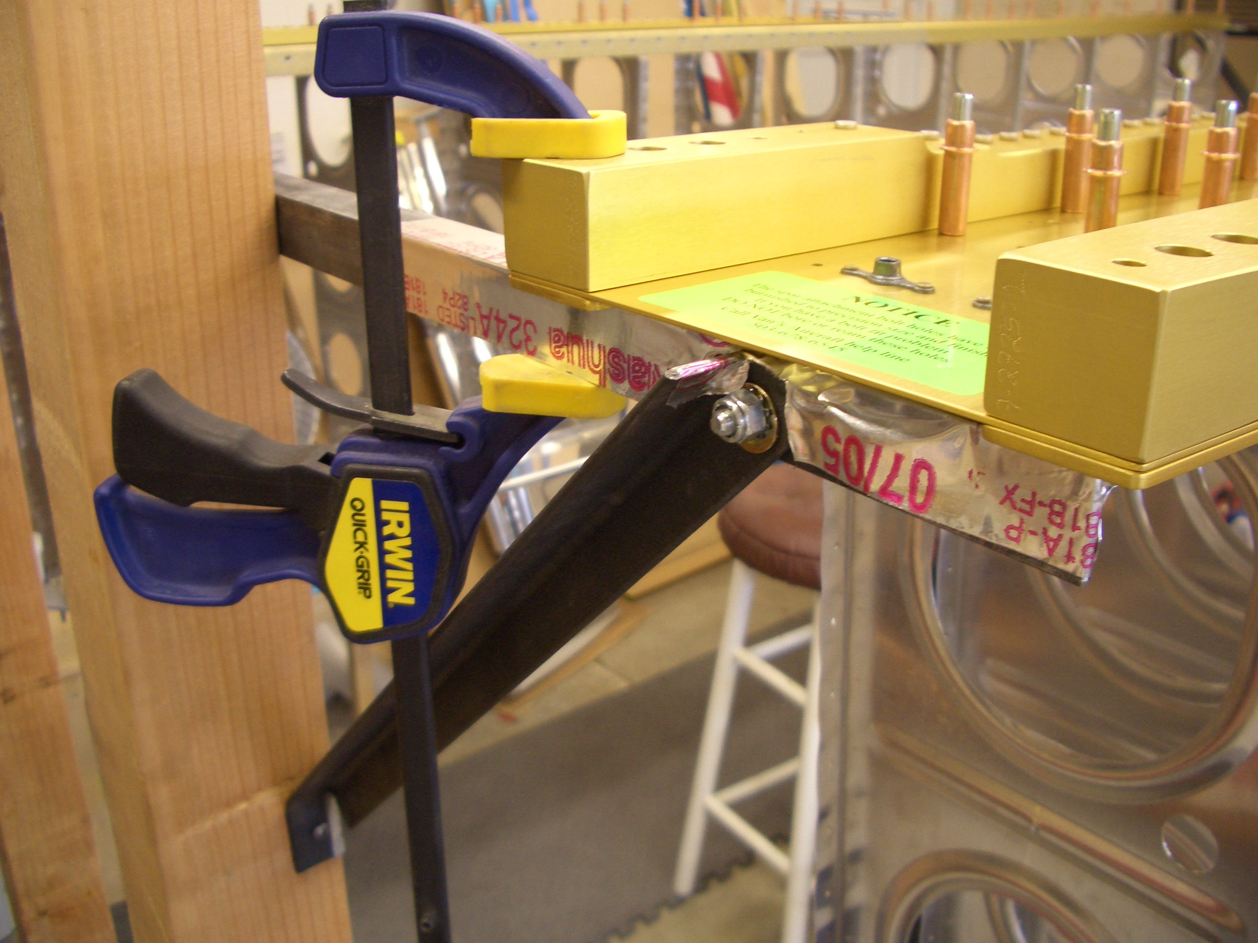
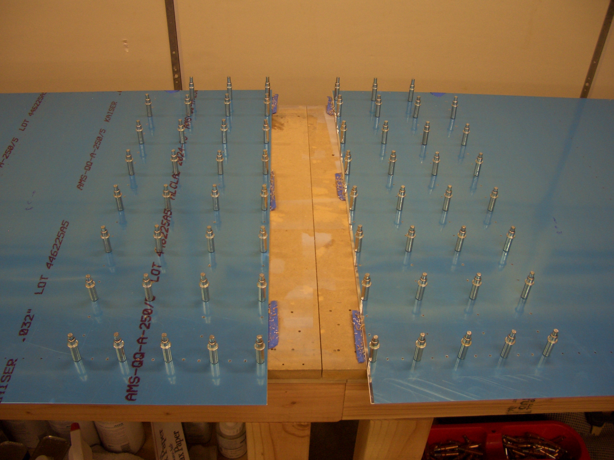
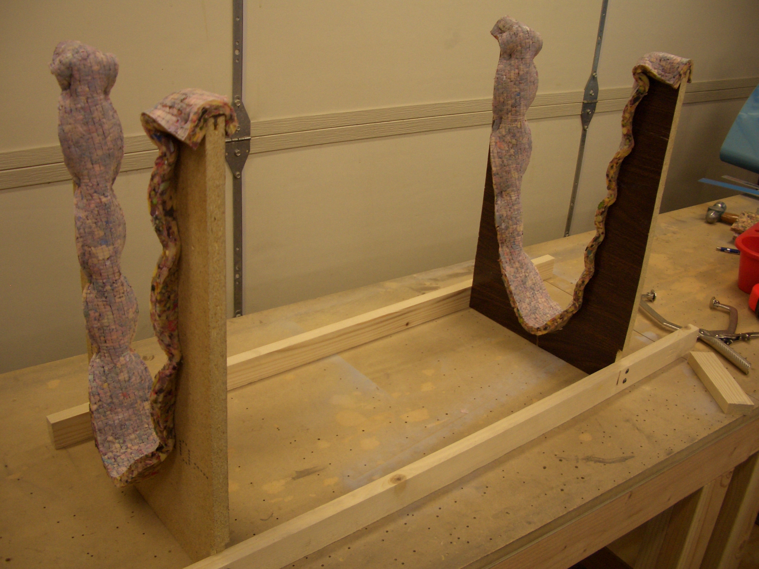
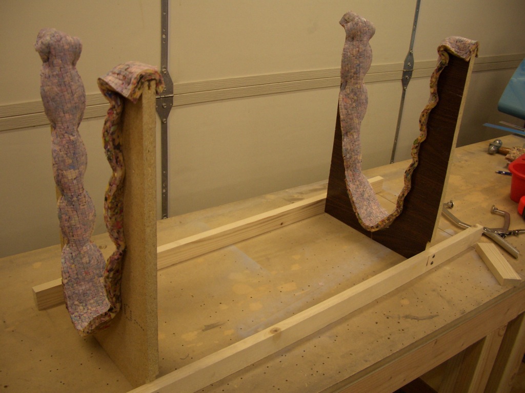
My buddy Andre stopped by tonight and drilled all of the bottom main skins while I worked on getting the leading edge skins ready to install. I started with fabricating a simple cradle to hold the skins while fitting the ribs. This is just a couple of pieces of particle board roughly cut to the shape of the ribs and lined with some old carpet padding I had laying around. The shape really isn’t that critical since it just needs to help hold the skins closed while you get the clecos in place.
Update: Particleboard is really the wrong material for this as this fixture will take a fair amount of abuse during the build. Both of these U shaped pieces broke near the bottom of the U while working on my outboard leading edges. I didn’t need them anymore, so I didn’t fix them, but save yourself the hassle and use plywood.
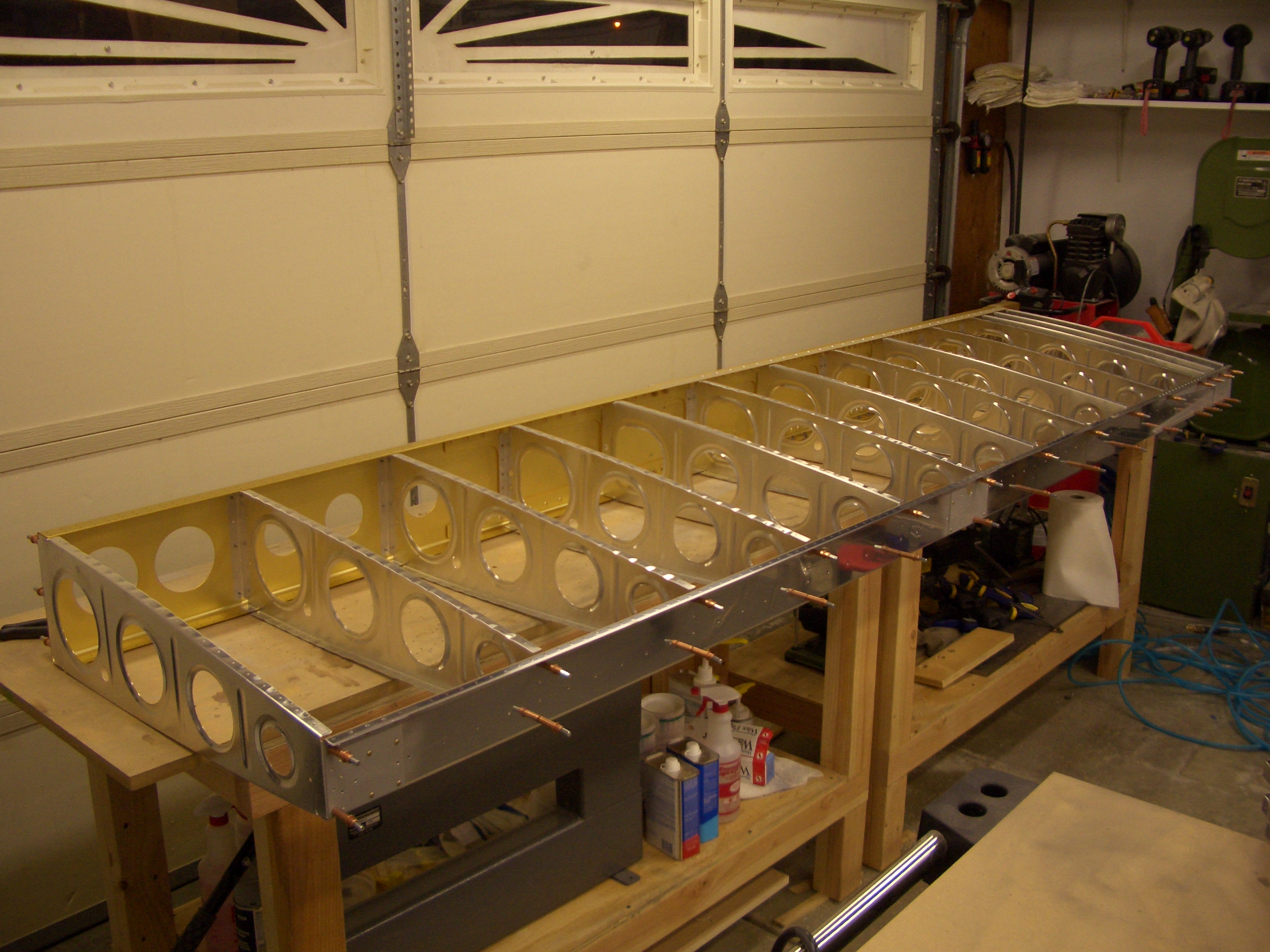
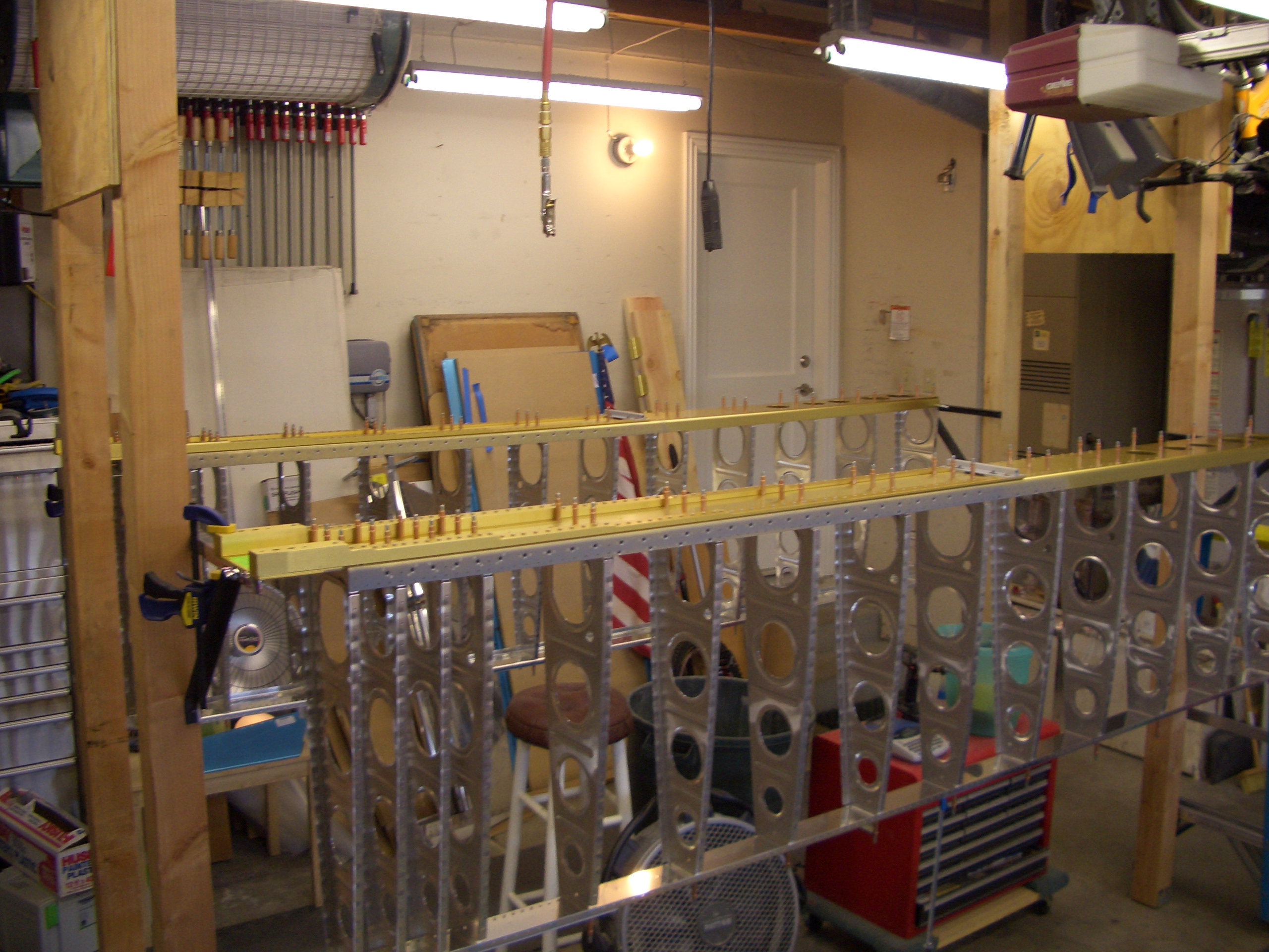
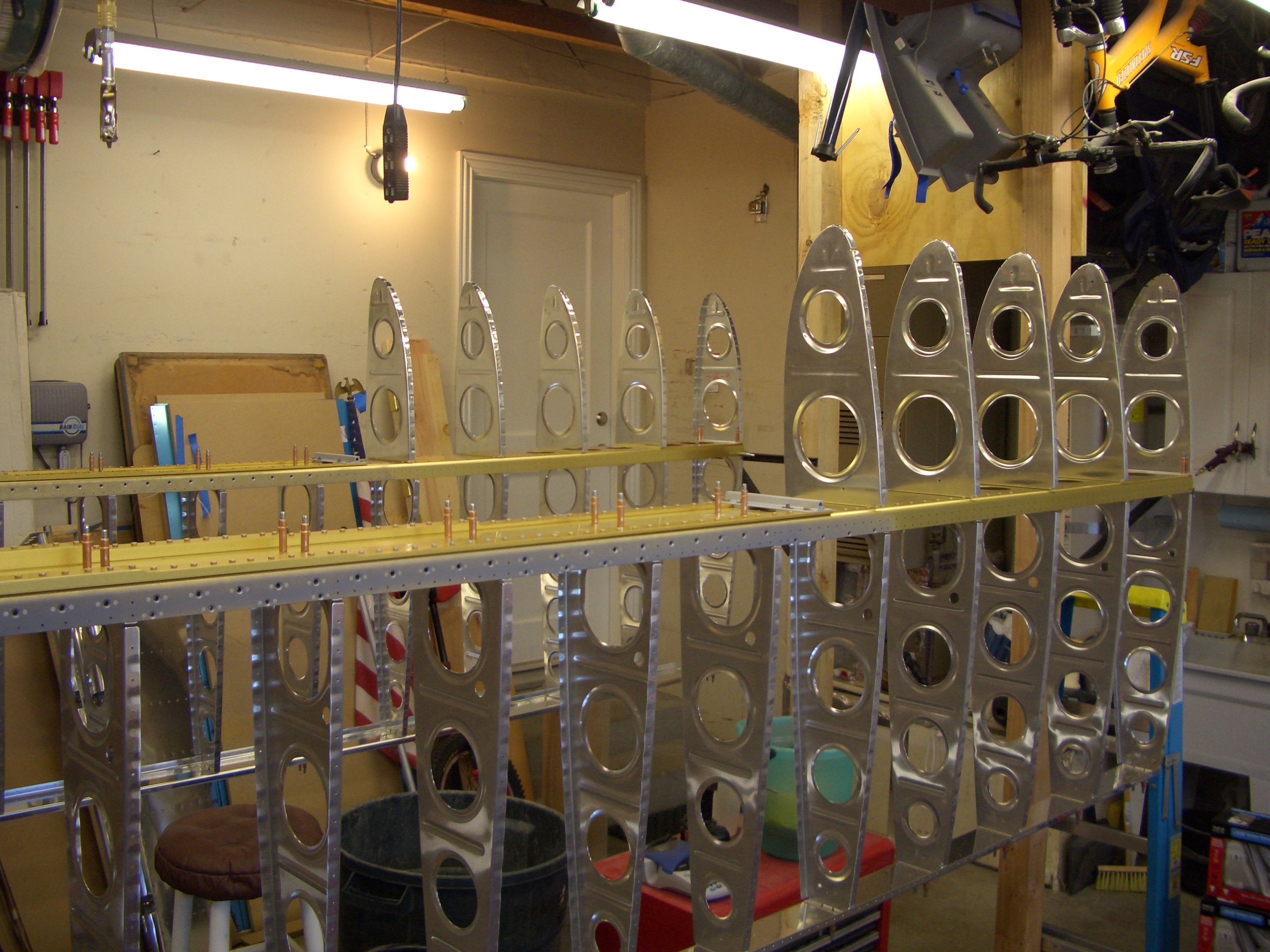
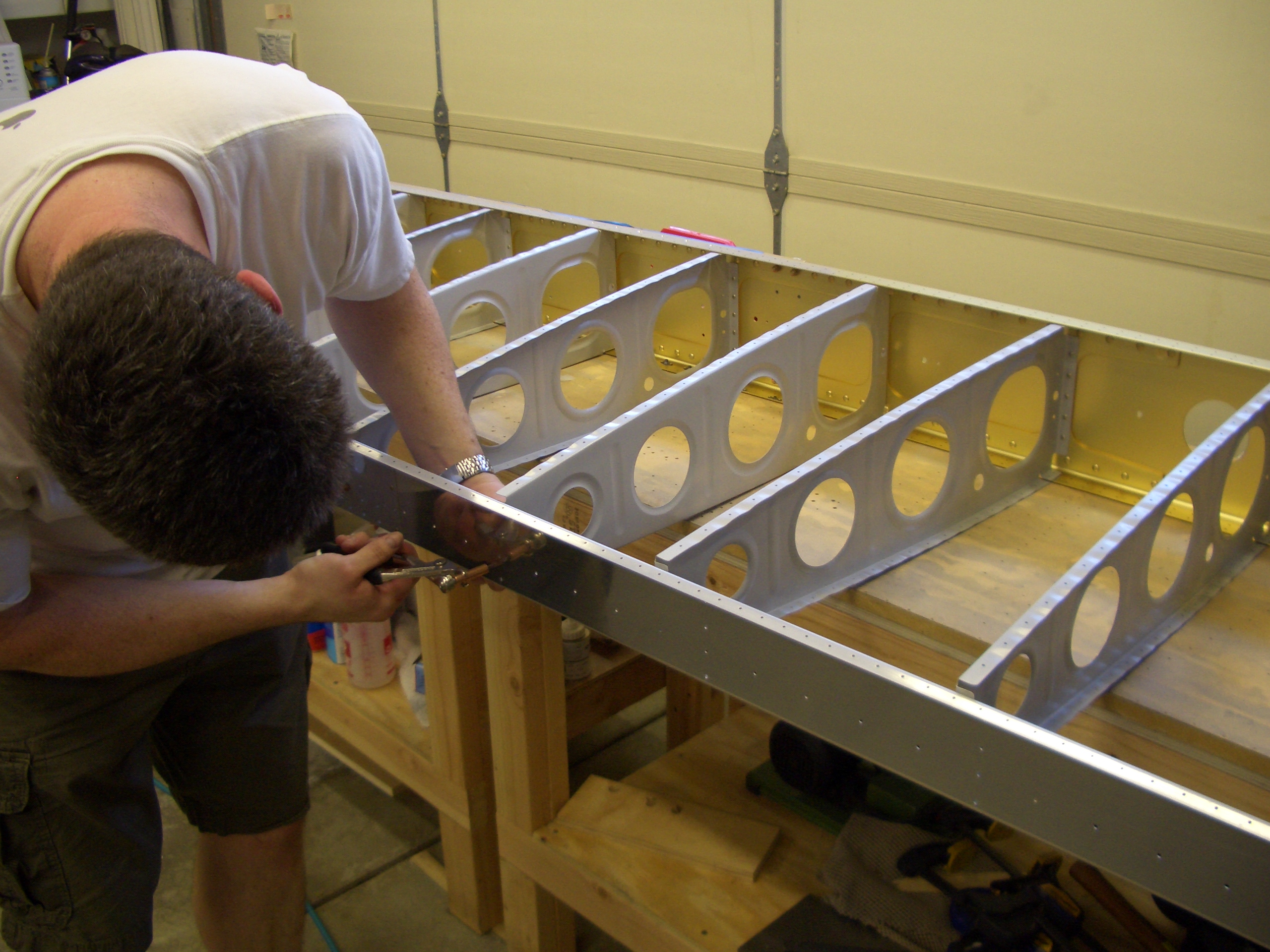
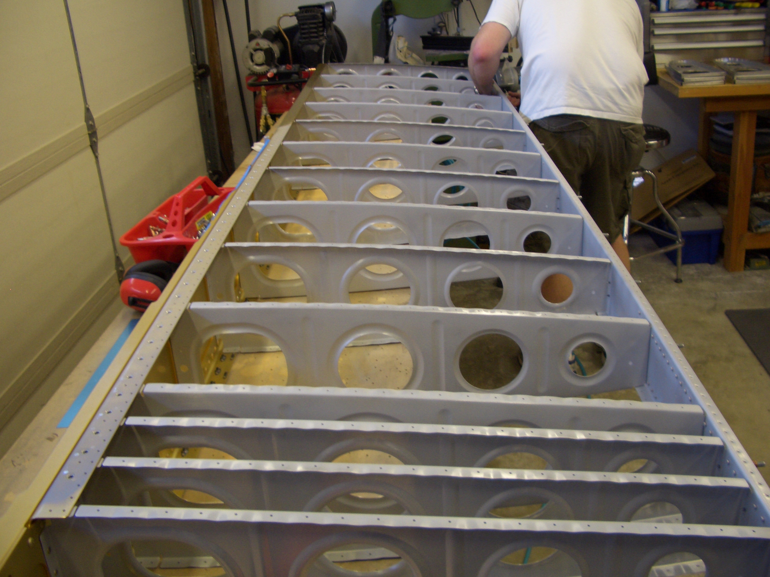
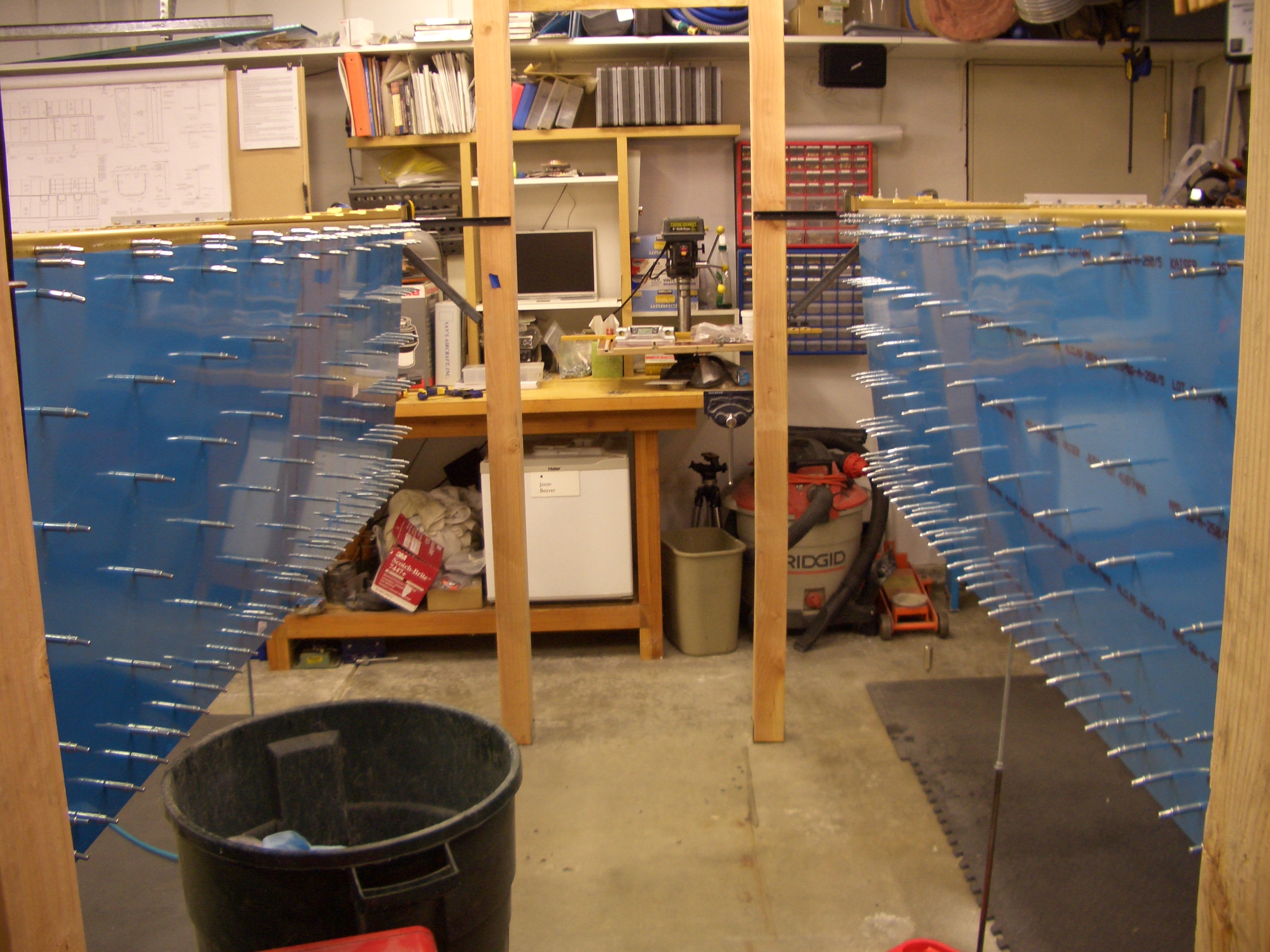
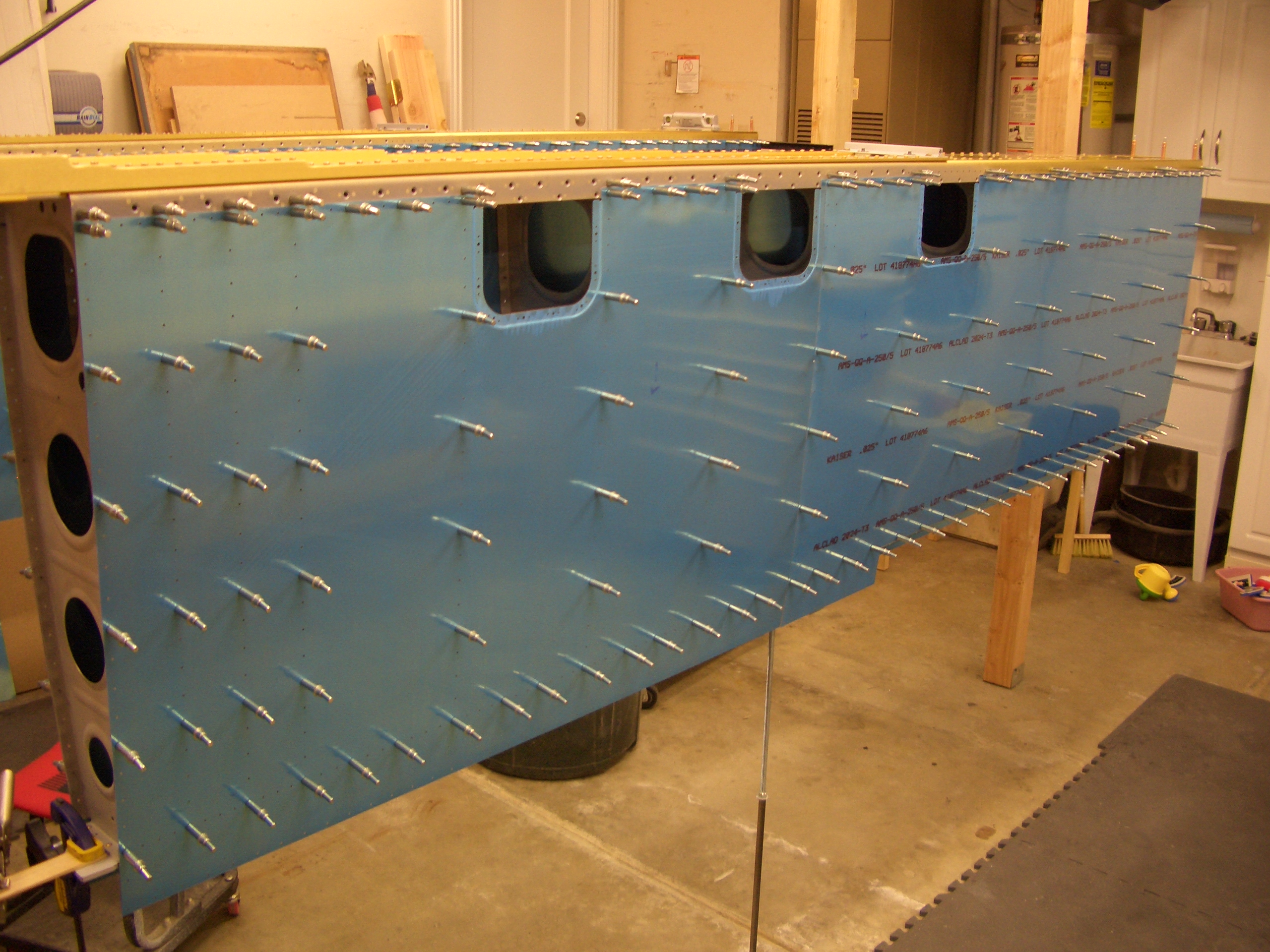
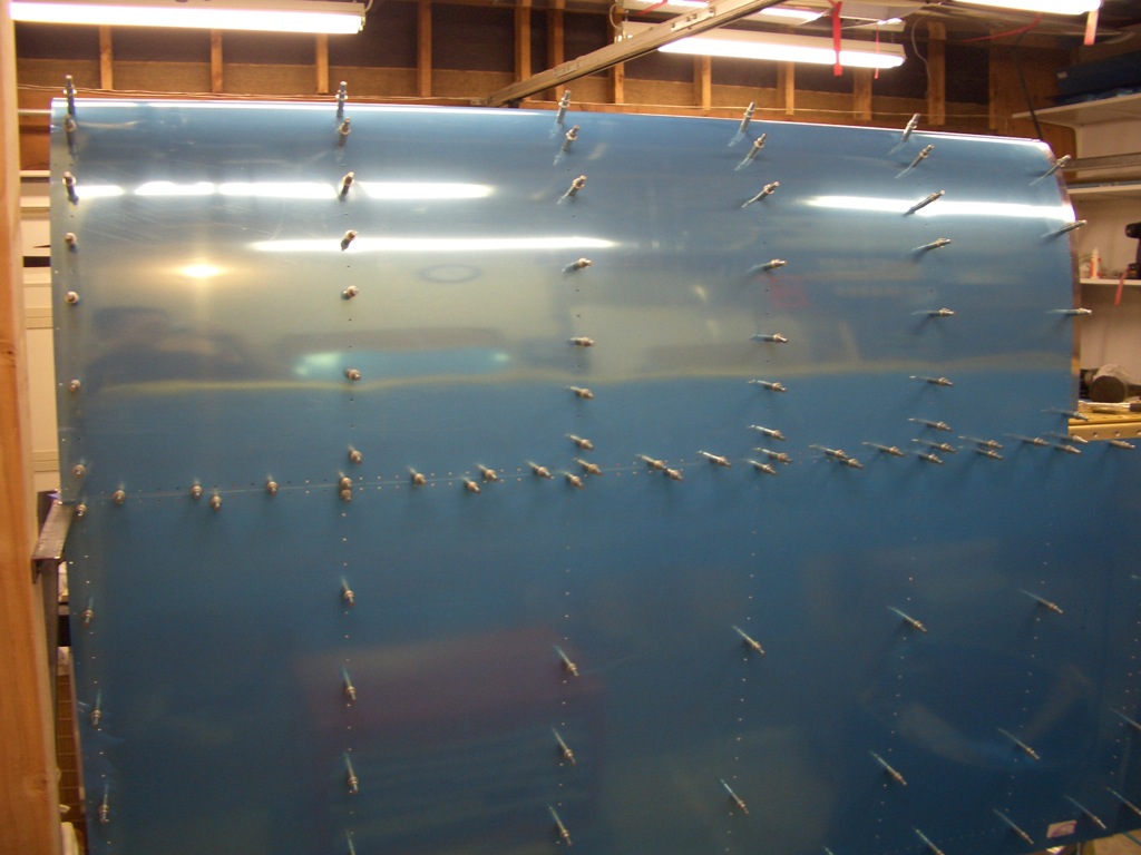
Andre and I clecoed the leading edge ribs into place and fit the leading edge of the left wing in place.
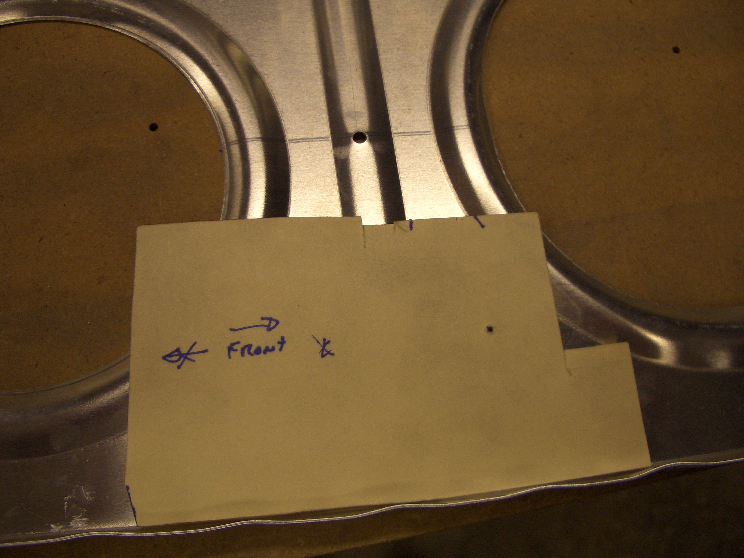
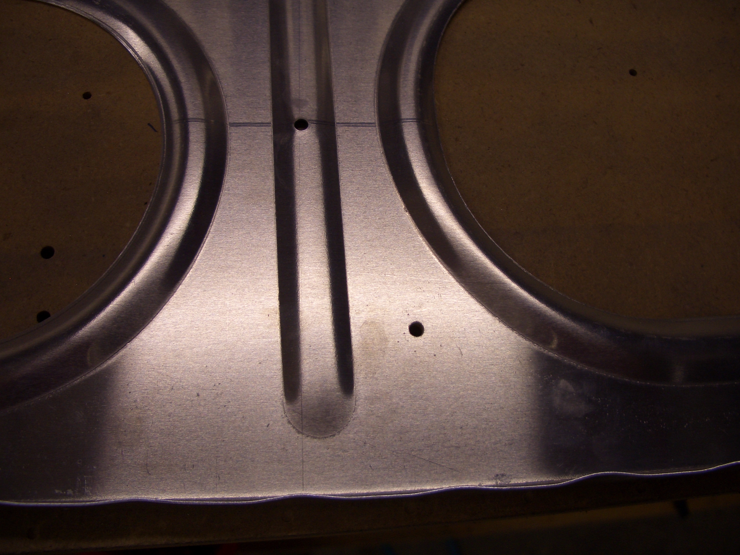
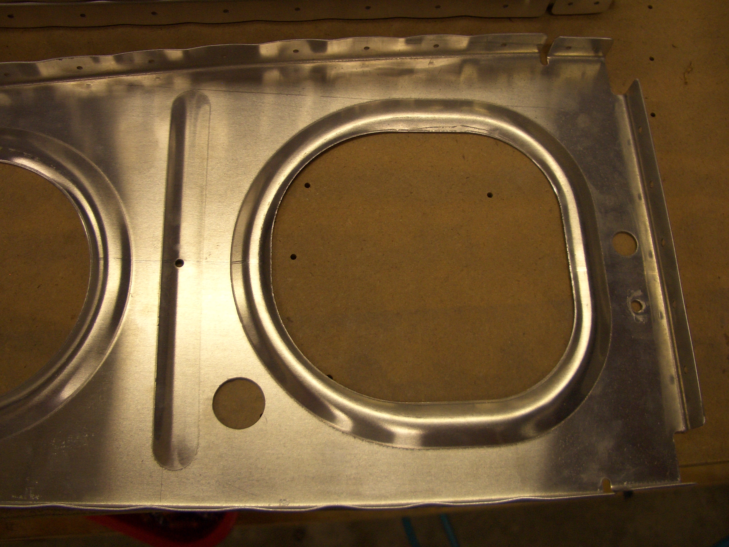
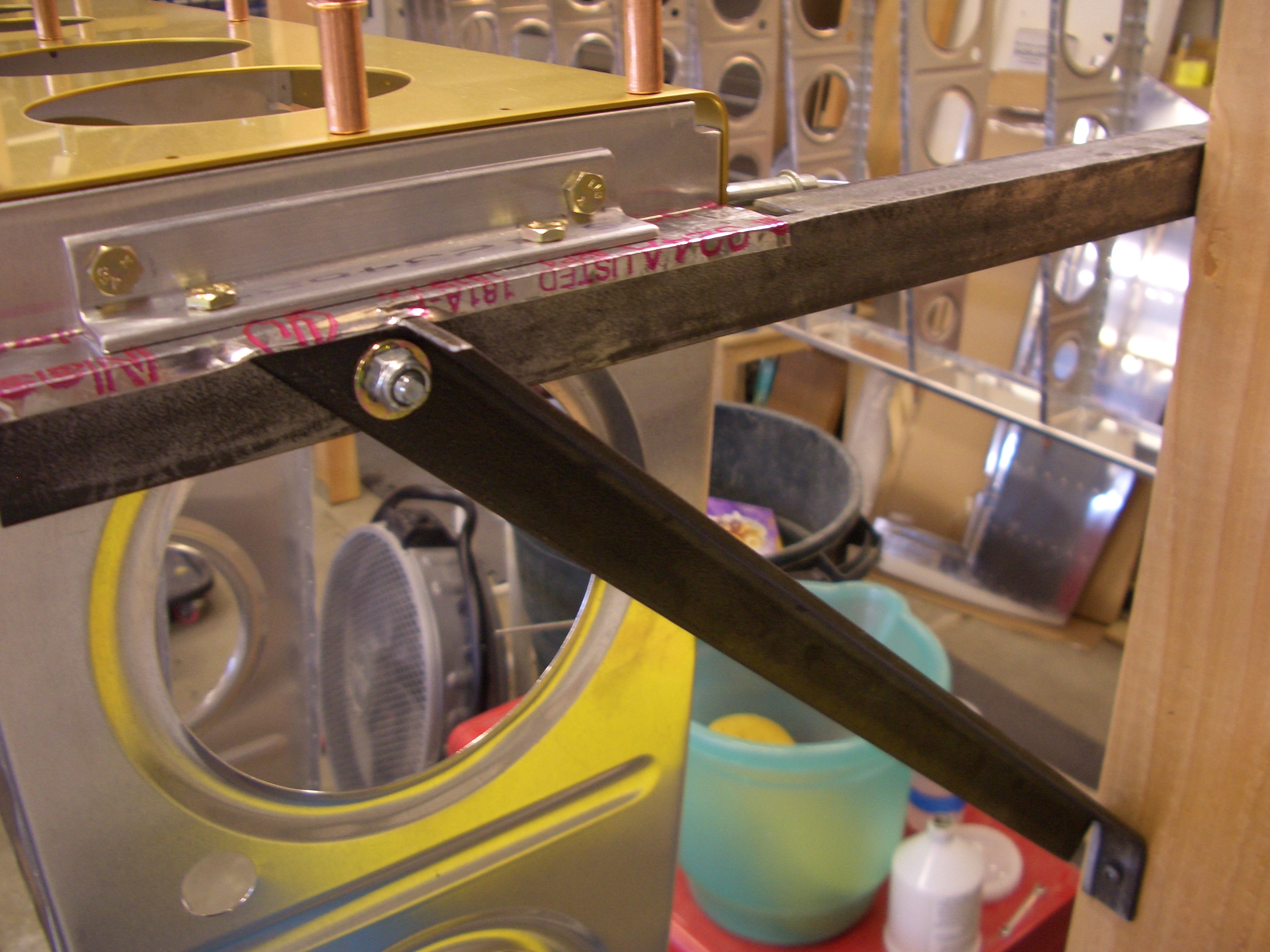
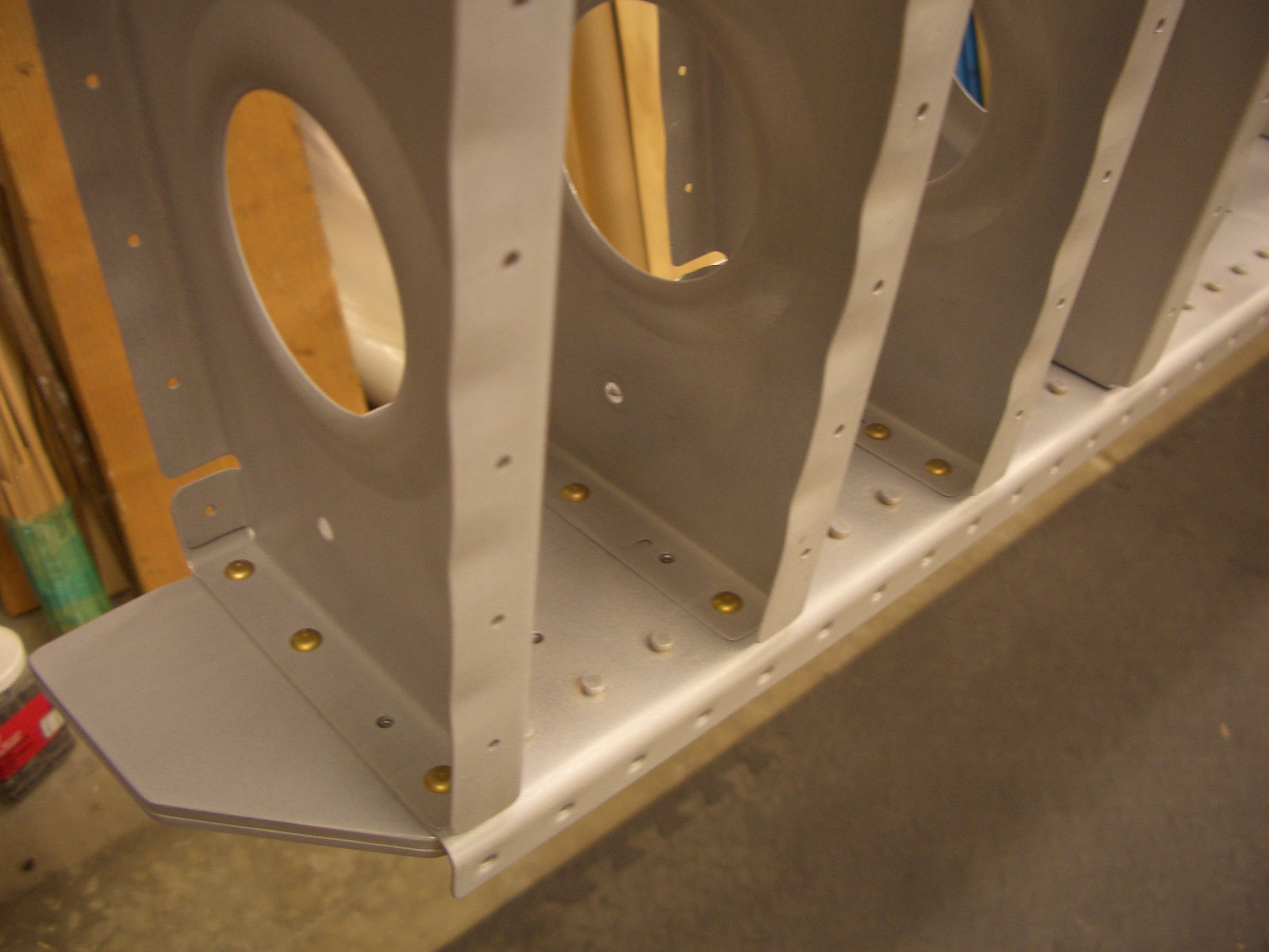
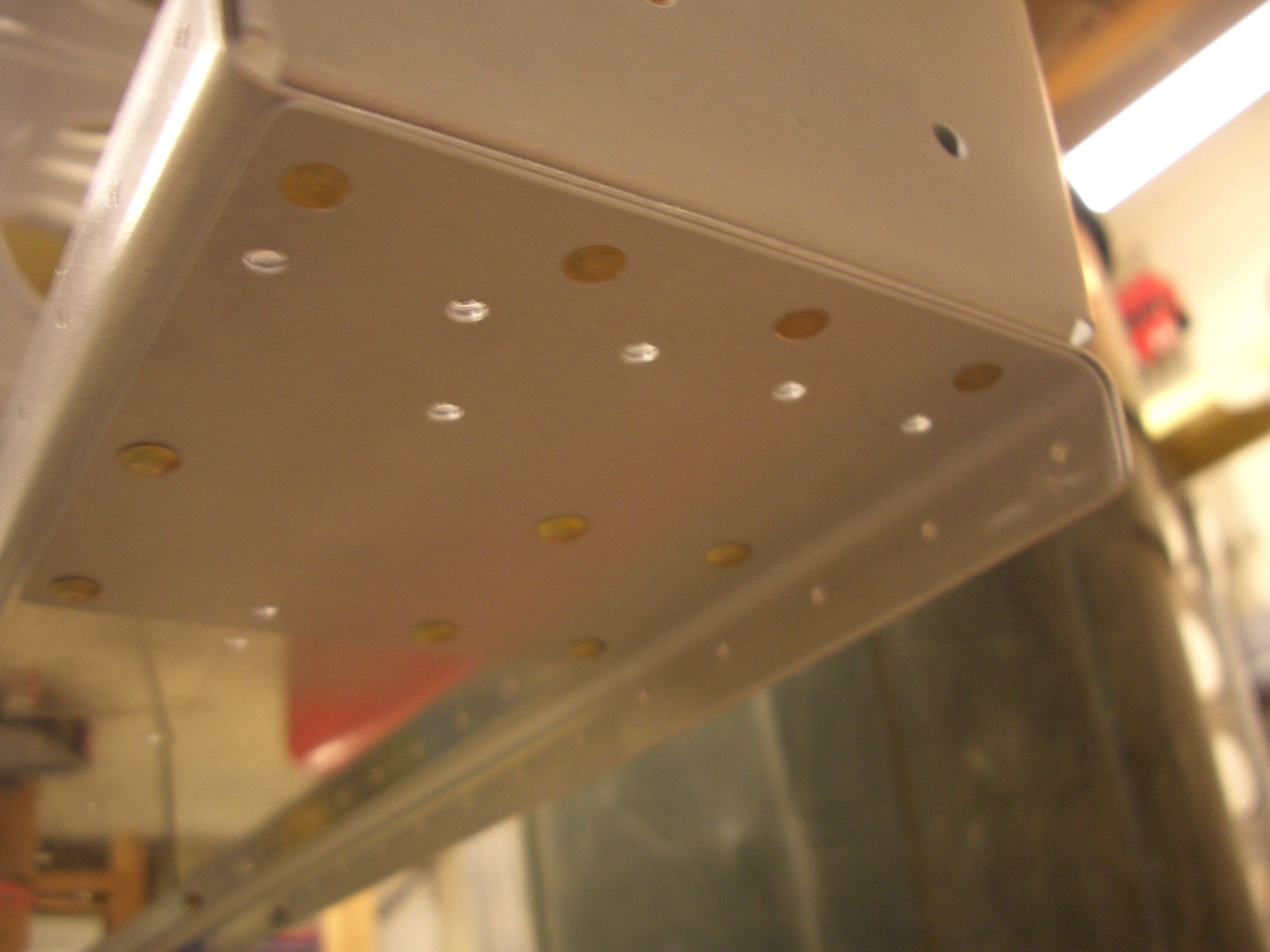
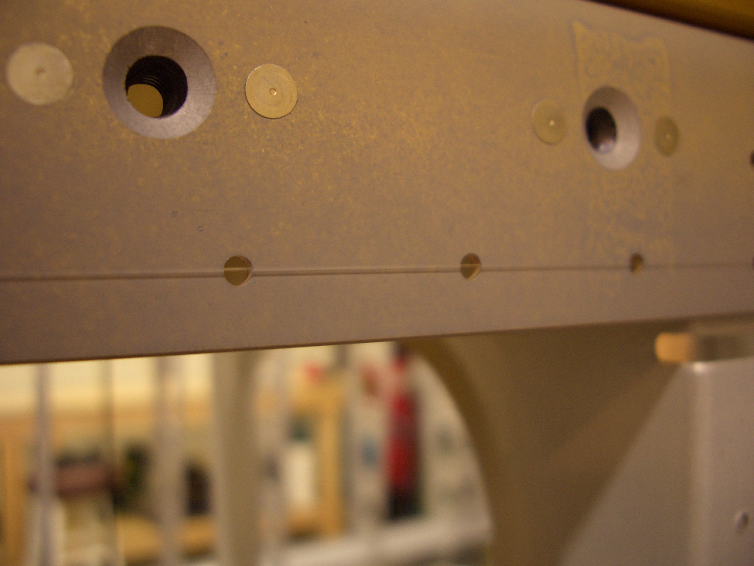
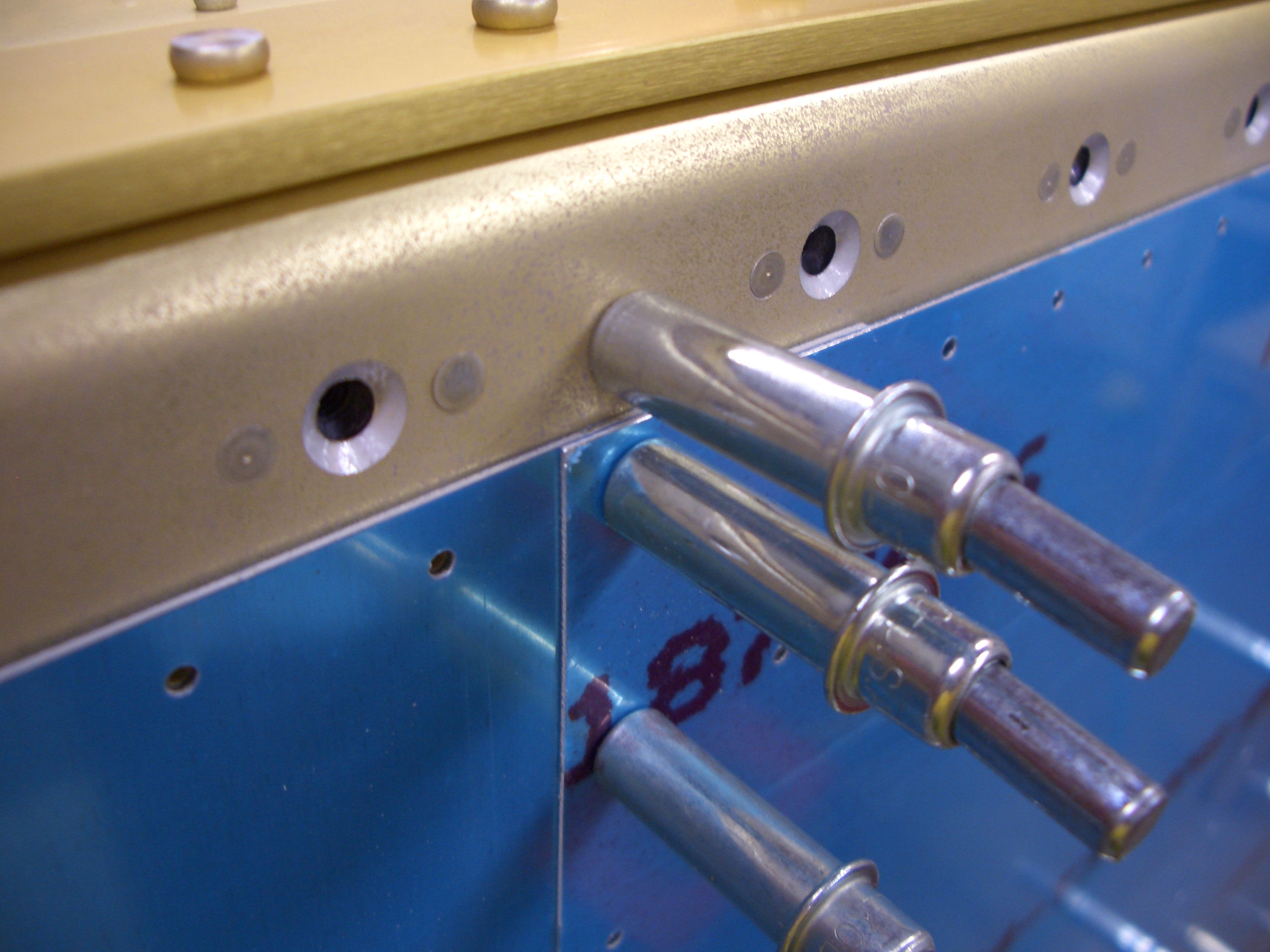
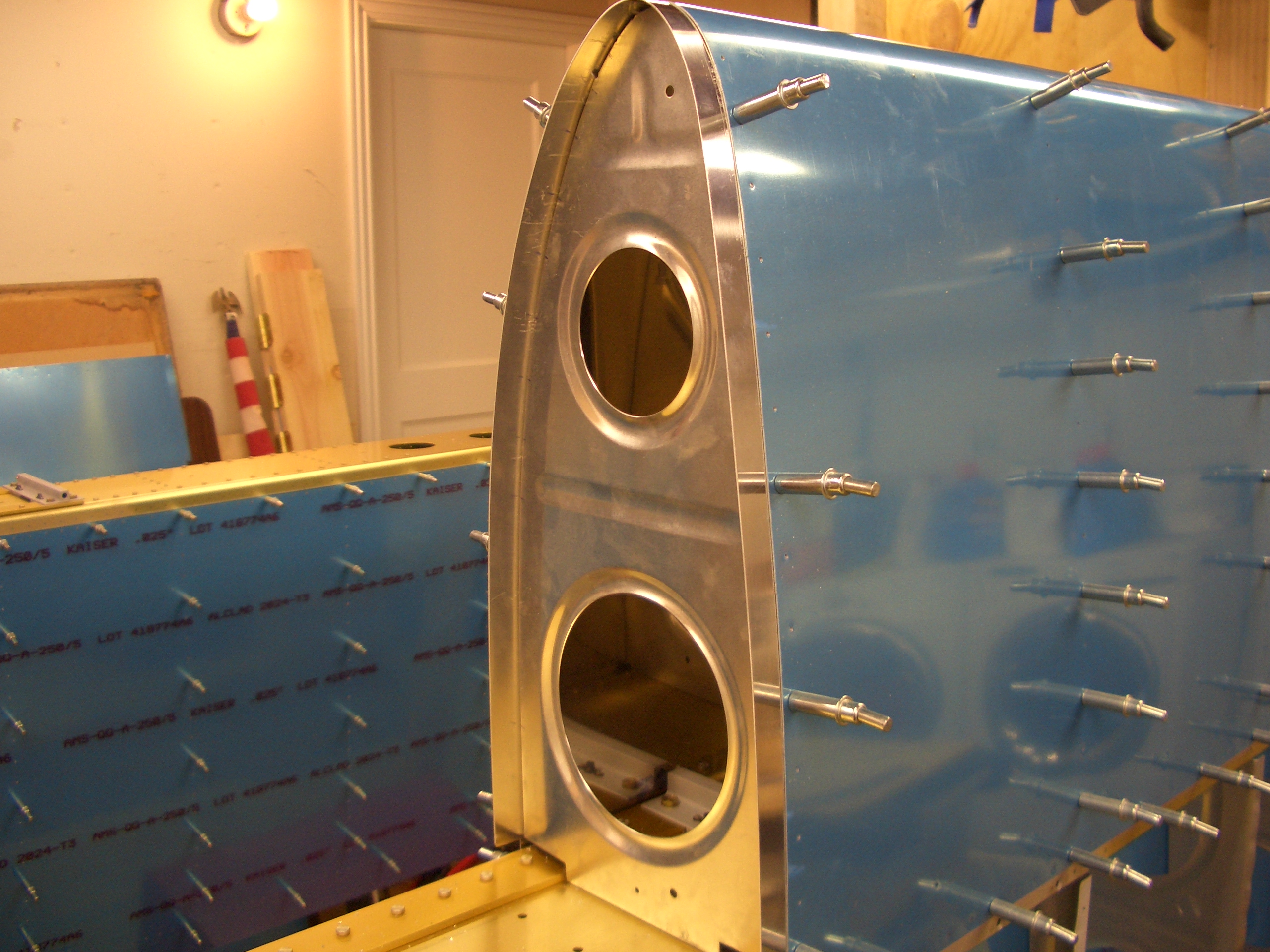
The innermost rib needs to be fitted with a joint plate where nutplates will mount to help hold the fuel tank. This was a real bitch since there are no holes in either the joint plate or the rib and the fit is
really tight. After futzing with it for about 10 minutes, I finally got everything in place and drilled a few holes to hold everything in alignment. The only issue I ran into was one of the holes that attach the rib to the main spar ended up with too little edge clearance. I doubt it will be an issue, but I’ll check with Van’s just to be sure.

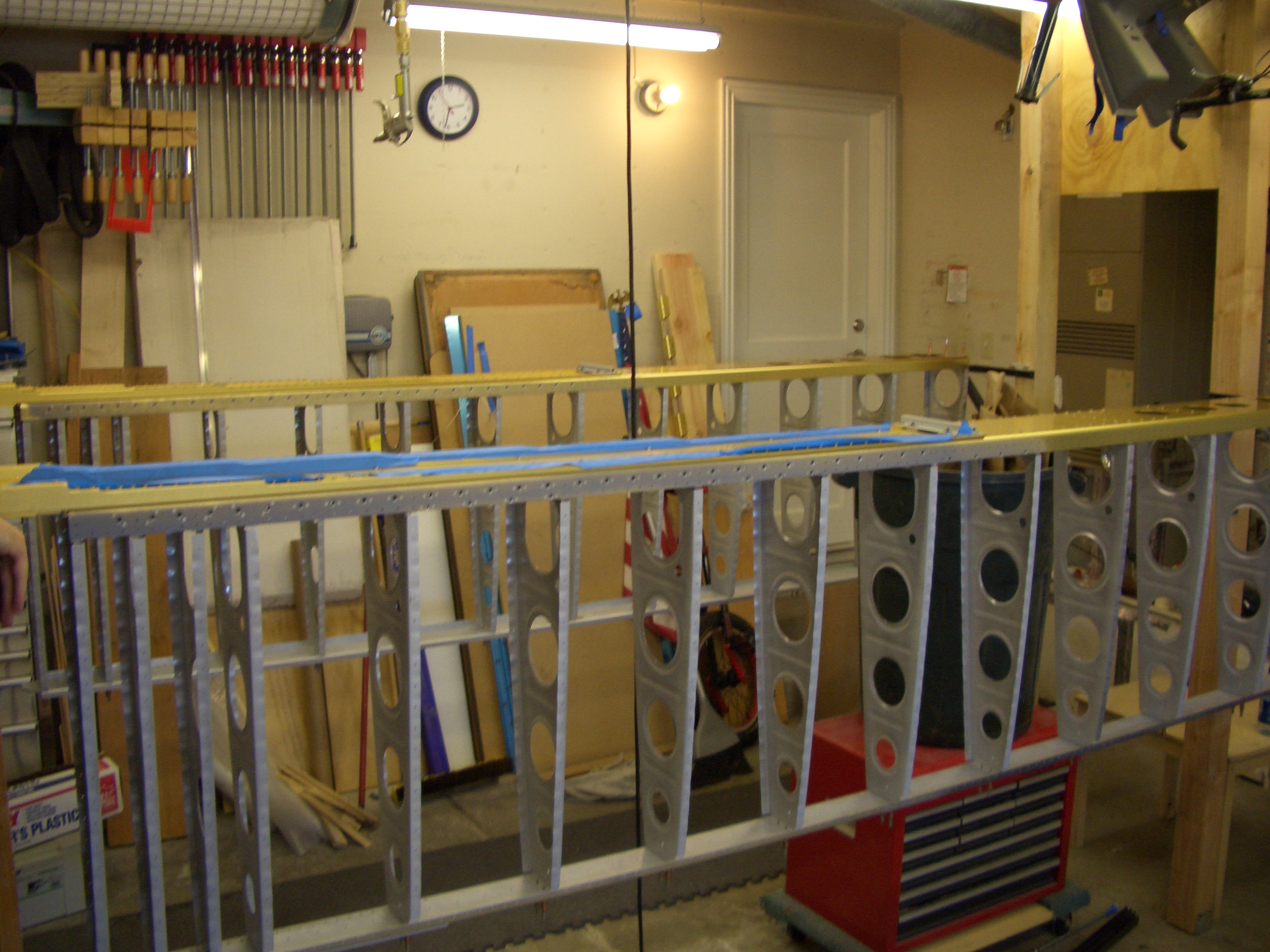
After Andre left, I knocked out the other leading edge in an hour or so. These still need to be match drilled, but that can wait until tomorrow.