Worked on Seat Pans and Baggage Floors

I finished tweaking the seat ribs today so that all of the holes in the forward seat pans lined up without having to pry the ribs into place.

I fit the right side outer seat rib and match drilled it to F-704.

I clecoed the aft end of the rib in place through the #30 holes (copper colored clecos) and drilled a single hole through the bottom skin (through the center line I previously marked) to define the lateral position of the rib and then match drilled the #12 hole through the bottom rear of the rib (gold colored cleco on the left).  The gold colored cleco sticking out of the side of the rib on the right was just used as a handle to tweak the lateral position of the rib.  I need to flute the center portion of the top of the rib to match the curve in the seat pan, so this still needs to come out again before I’m ready to match drill it to the seat pan.

Finished Seat Ribs and Longeron Cutouts

I positioned the web of the outboard seat ribs 1/32″ past the end of the seat pans and drilled the top flanges out with #19 near the front (the black cleco near the upper left of the picture) and #30 the rest of the way.  Afterward, I clamped my tungsten bucking bar to the forward end with the tip just hanging over the F-704 side doublers.  This ensures these two parts are perfectly coplanar since the side skin spans this joint.  I then drilled the first hole in the bottom skin to lock in the lateral position of the rib.

The center line that I drew on the bottom flange of this rib was perfectly centered for the entire length of the rib, so I match drilled it to the bottom skin.

Here is the rib fully drilled to the center section.  I then repeated these steps on the left side.

Before the center and aft fuselage sections can be mated, a notch has to be cut in the longerons to allow the vertical bars on F-711 to slip through.  The plans provide dimensions on where to position this aft deck, and the existing slot can be used to mark for the notch.

After drilling the end to just under 3/16″, I used a mini hacksaw to cut out the waste (a regular hacksaw would have required me to remove the aft deck to make the cut).  I then filed the longeron until it exactly matched the cutout in the aft deck and had a perfect 3/16″ radius starting 1/8″ from the outer leg of the longeron.

I then repeated the procedure on the other longeron.  I’ve noticed several builders drilling two 3/32″ holes to define the radius at the end of the notch, but check the plans carefully, the radius is supposed to be 3/32″, so you need a 3/16″ diameter curve at the end of the notch.  I filed this until a 3/16″ drill but nestled into the curve.  I still need to smooth everything out with some scotchbrite, but the aft and center fuselage sections are ready to join.

Joined Center and Aft Fuselage Sections

After rearranging some things in the garage, Jenn came out and gave me a hand joining the center and aft fuselage sections.  I ended up having to remove the baggage floors in order to be able to coerce part of the bottom flange of the baggage ribs to fit over the F-706 bulkhead.  Do yourself a favor and just leave the baggage floors out until you get the bottom skins clecoed together.

Here is what it looks like underneath.  The baggage ribs also cleco to F-706.

It looks like I nailed the downward bends in the longerons.  They perfectly follow the angle on F-704.

The front edge matches up perfectly.

Here’s the other side showing how accurate these bends ended up.

It was very late (after 12:30 am), but I just had to cleco on the side skins to get a feel for how big this thing it.  I ended up having to remove the shim under the tail to get the holes to pull in to alignment, but now everything fits perfectly.

I’m starting to have serious space problems in my garage.  I’m going to have to move my benches around just to be able to walk from one side of this to the other.  Fortunately, my next door neighbor offered to let me store my wings in his garage (tied up to the rafters), so that will free up a ton of space.

Drilled Armrests and Made Conical Bend on Left Side

I drilled the armrests to the side skins and F-704 and F-705 (although the fuselage is upside down, I took this picture upside down so this is how the armrests will look from the cabin).  The arm rests need some minor fluting to get the holes to line up in the side skin.  This is unfortunate since this will be seen in the cockpit unless I add upholstery on the side walls.

The armrests are pretty flimsy, and I’ve heard numerous stories about people bending these when passengers get in and out of the plane.  There are several ways to strengthen these, so I’ll almost certainly modify them so they’re stronger.

Where the side skin meets the aft fuselage, this “ear” must be bent into a conic shape.  I first deburred the notch near the tight end of the cone since I’ve heard of several builders getting cracks there while bending.  I then clamped my back-rivet plate along the bend line and drilled a piece of scrap 1/8″ angle to the existing holes.  Afterward, I used the large crescent wrench seen here to create the bend.

Here is the left skin clecoed back in place.  Overall, this turned out pretty well and no cracks!

Finished Conical Bend and Started Drilling Longerons

I made the conical bend on the right skin and it came out even better than the one of the left.  I know that it looks like there is a gap between the side skin and the bottom skin, but that’s just because for some reason I already dimpled the bottom skin, and that’s holding the bottom skin away from the side skin.  After the side skin is dimpled and everything is riveted, it will pull together nice and tight.

Next, I clamped the left longeron to the side skin (ensuring that the apex of the angle was flush with the edge of the skin), and match drilled it to the skin.  There are 180 holes here, and since there were no holes in the longerons to start, the holes take much longer to drill.  This was about 1.5 hours to do these holes.  I would do the other side, but that would keep me up until 2 a.m. and I’m already starting to come down with a cold, so I should get some rest.

Notice that the frontmost (lower right in this picture) seven clecos are copper colored.  Those are 1/8″ holes where the skin and longeron attach to the upper engine mount.

Here is the inside of that section.  The instructions specify that the end of the longeron needs to be cut back 3/4″ from the forward end of the skin.  It’s odd that the prior instructions give such precise dimensions, and then this step has you cut it even shorter.  Furthermore, the instructions specify that if you are a little short not to worry about it.

I intentionally left this long now so that I can ensure that I leave sufficient edge distance on the frontmost rivet.

Finished Drilling Longerons and Hung Firewall

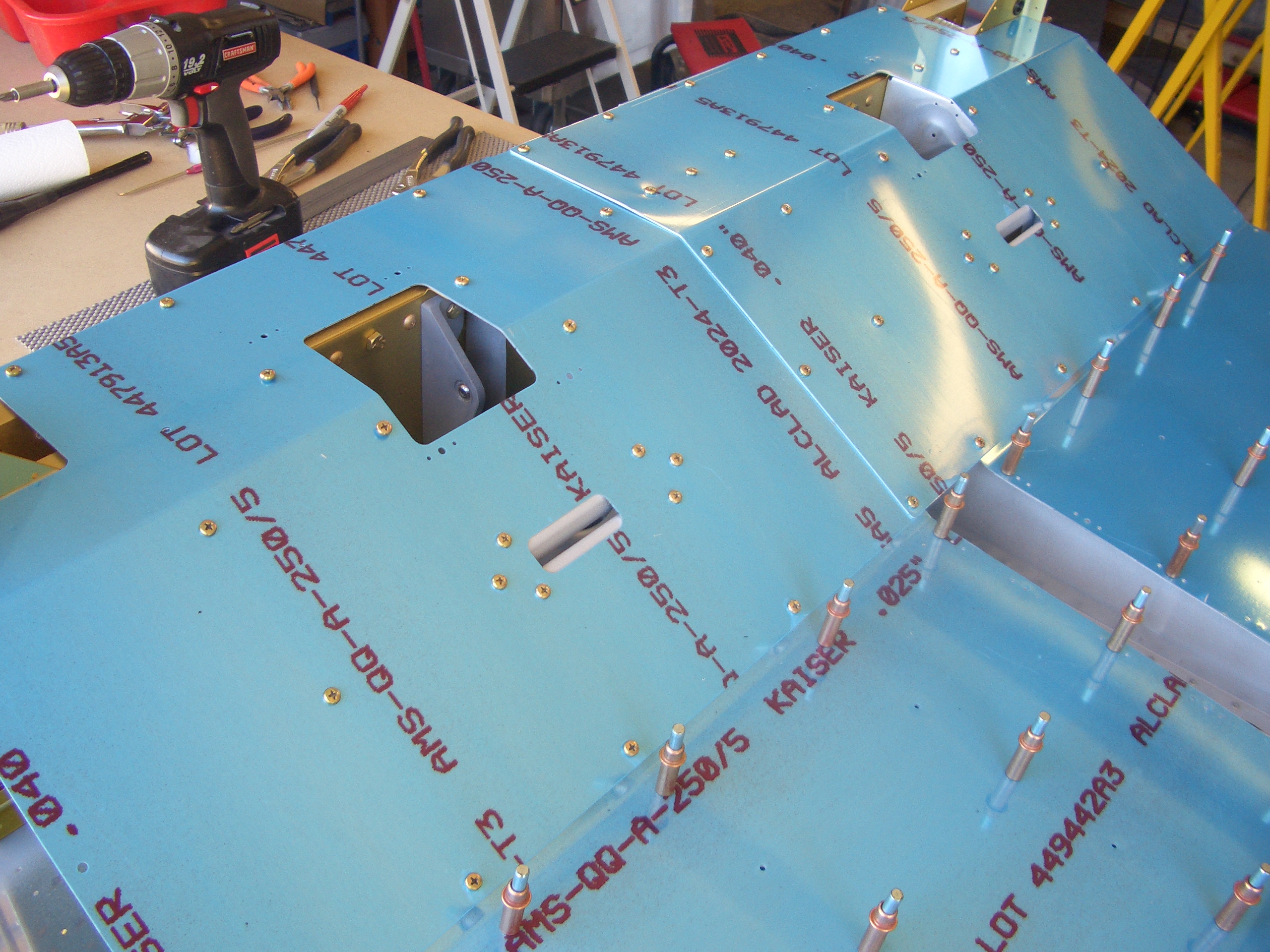
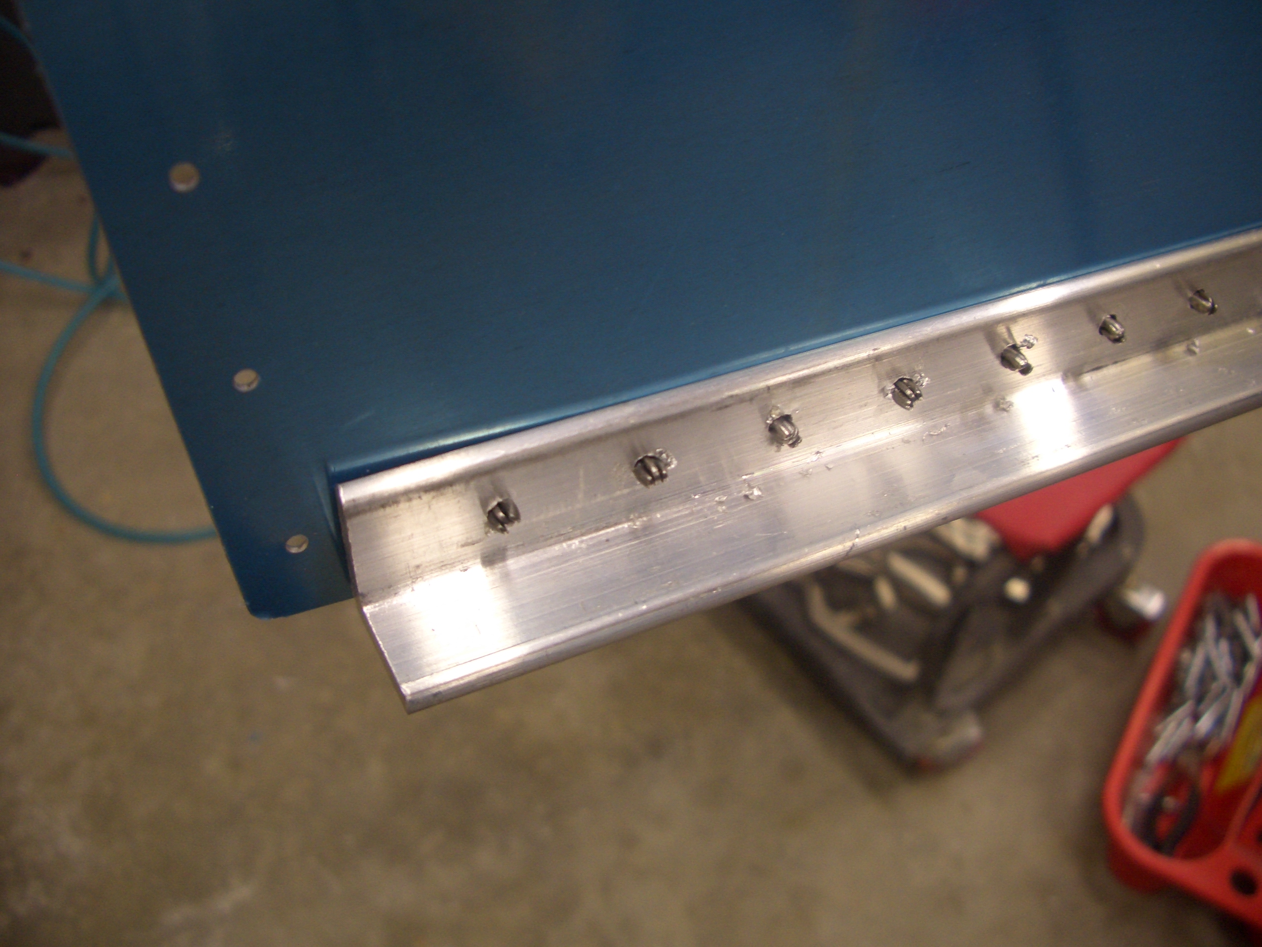
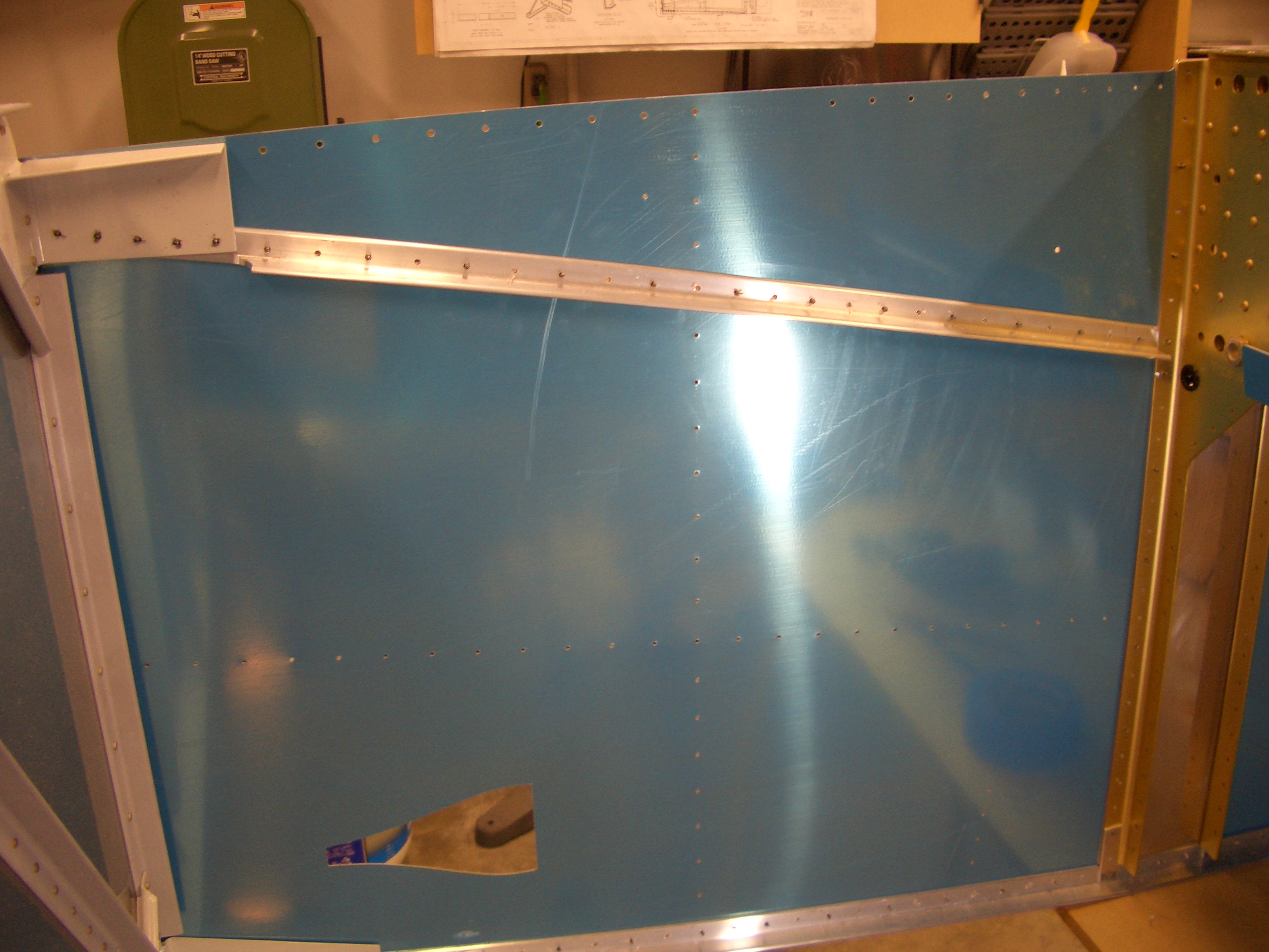
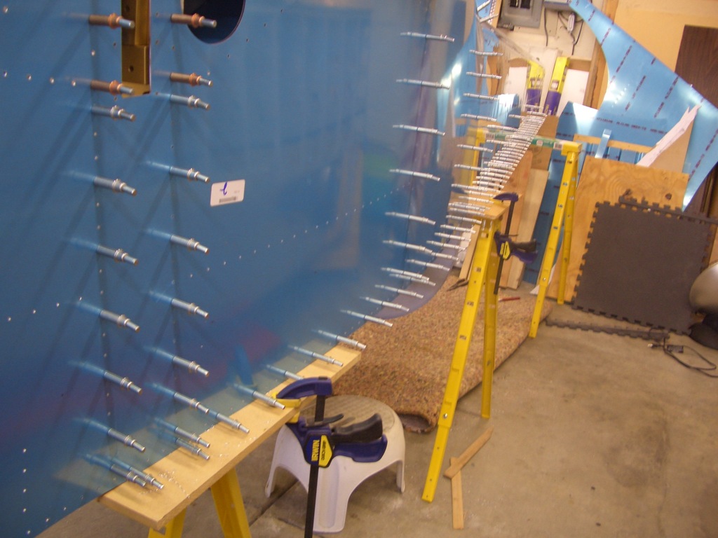
I came out this afternoon and drilled the right longeron to the side skins.  This went much quicker than the left since I switched to a new sharp 3/32″ drill bit.

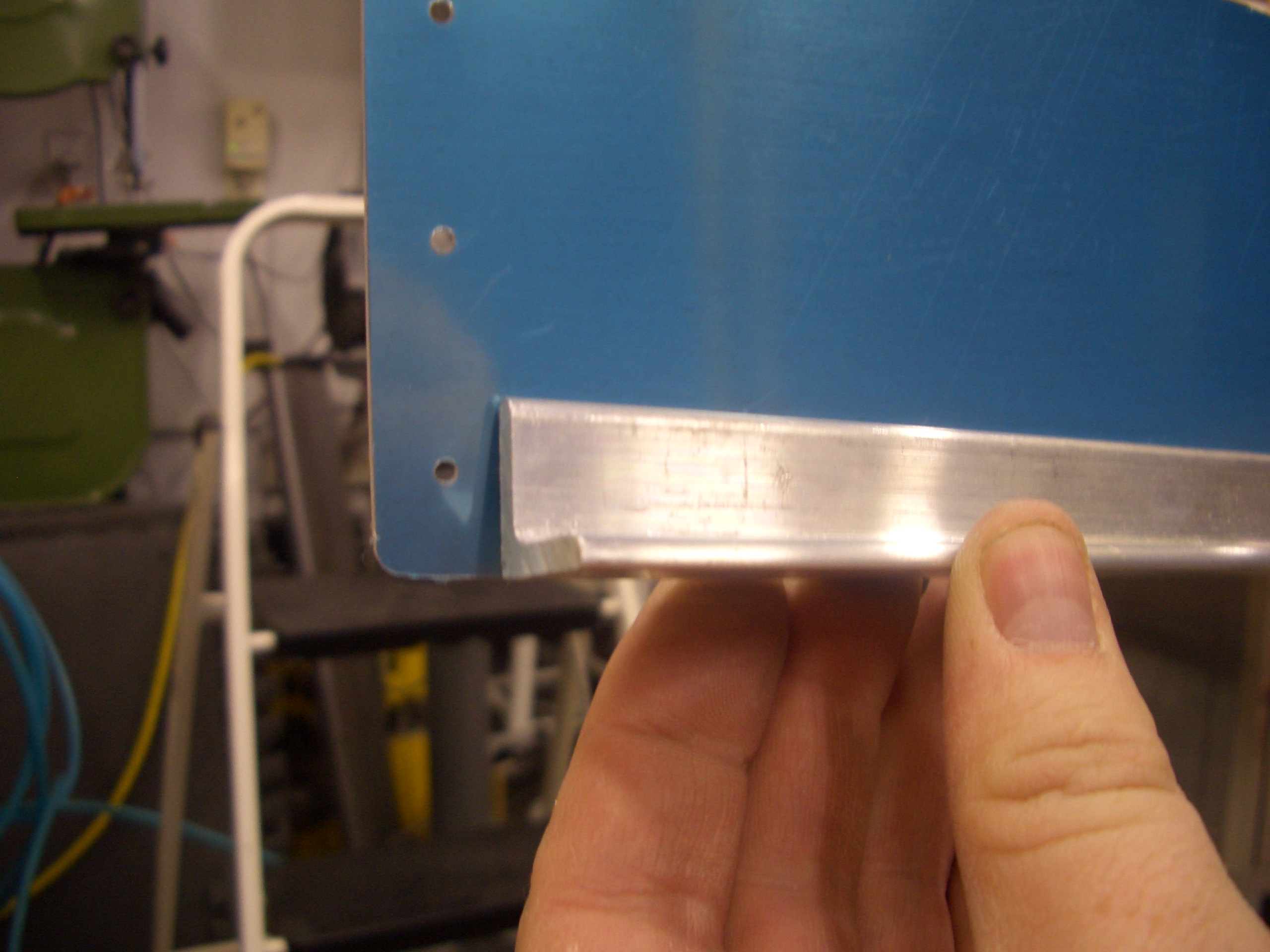
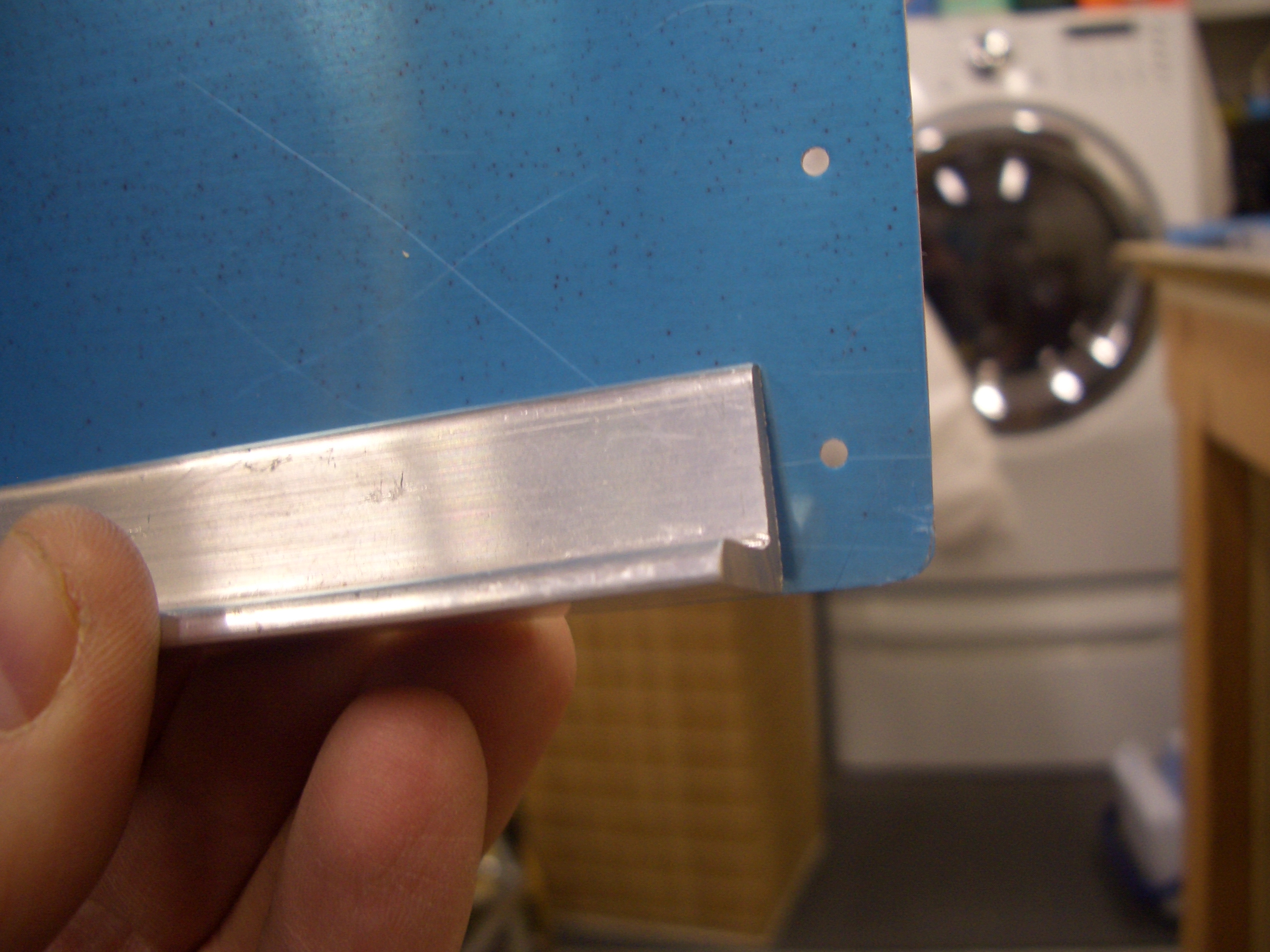
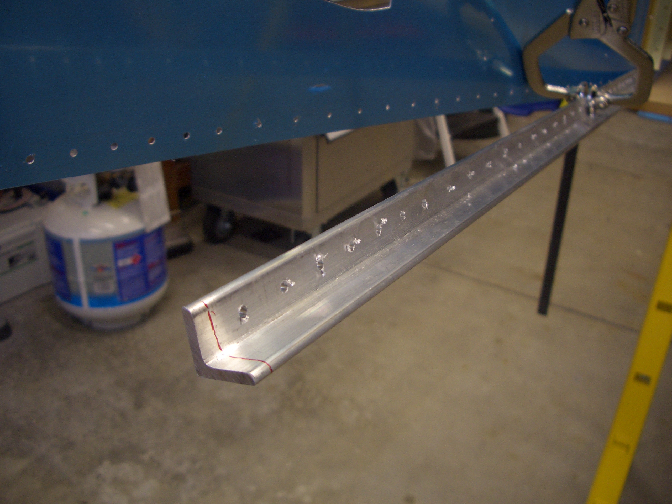
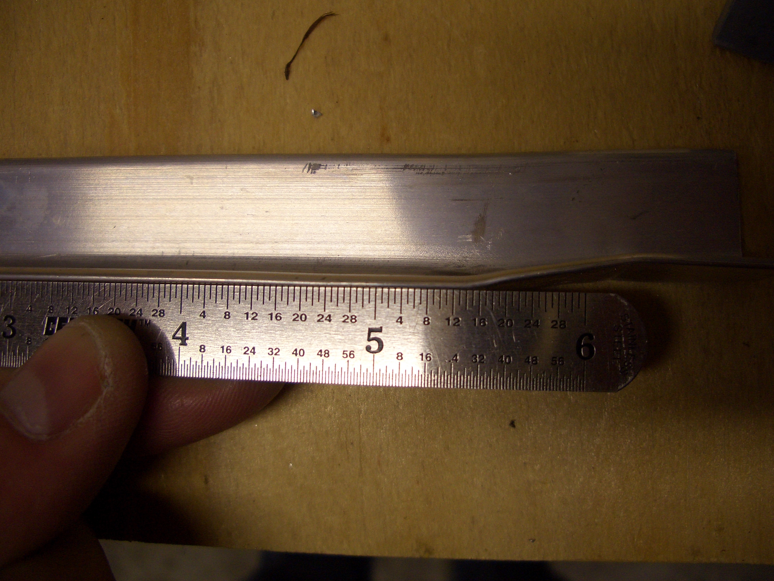
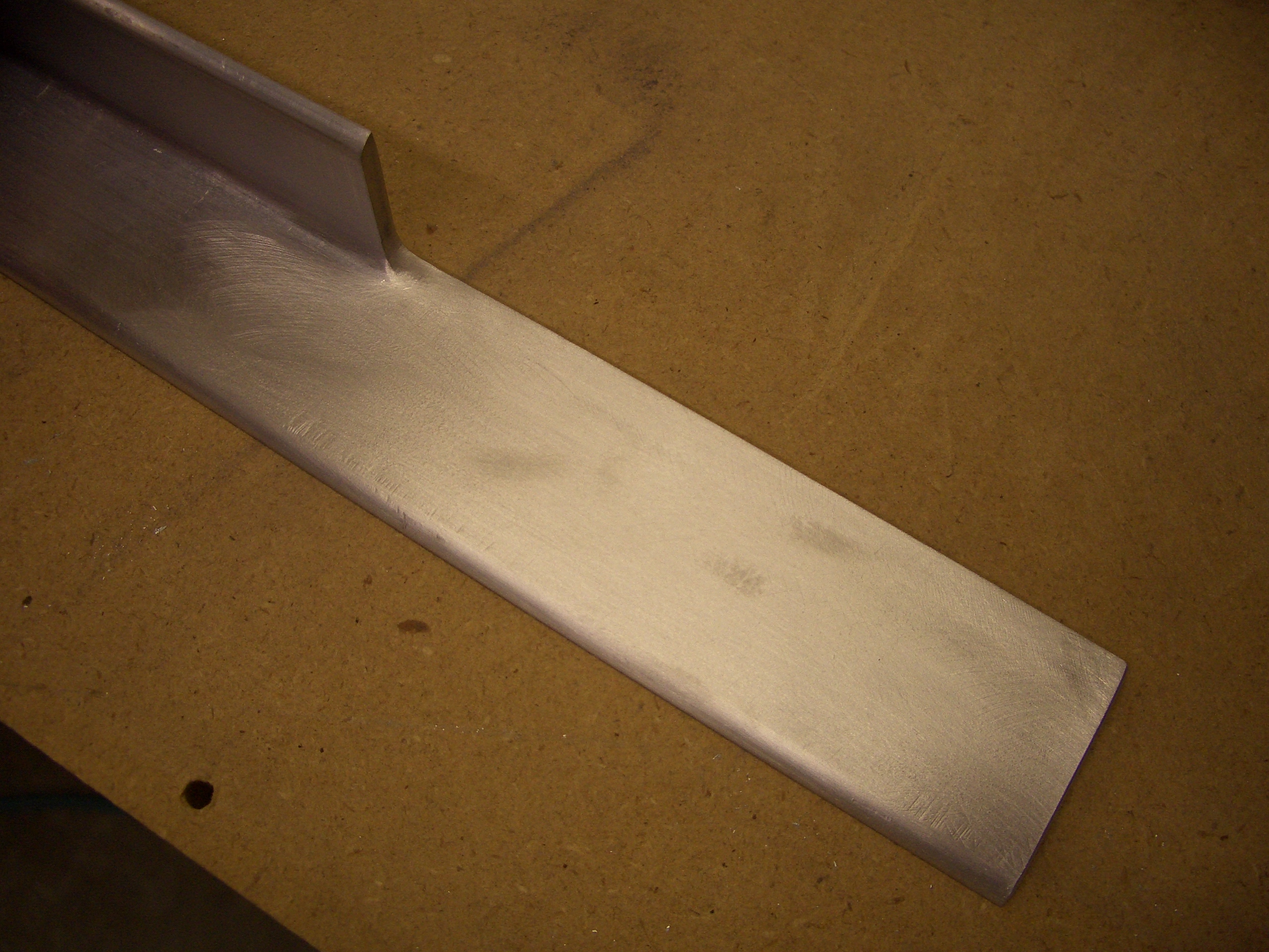
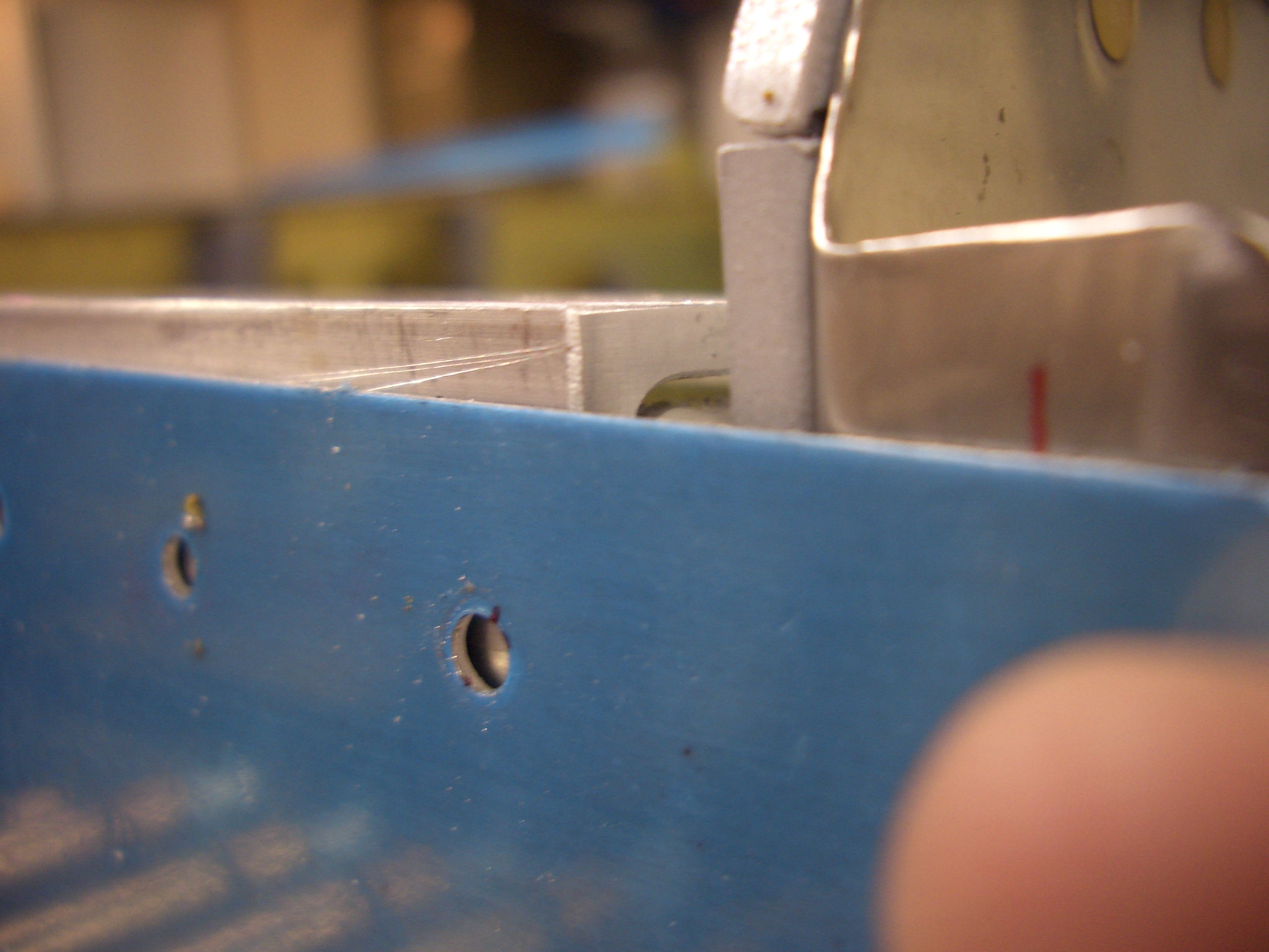
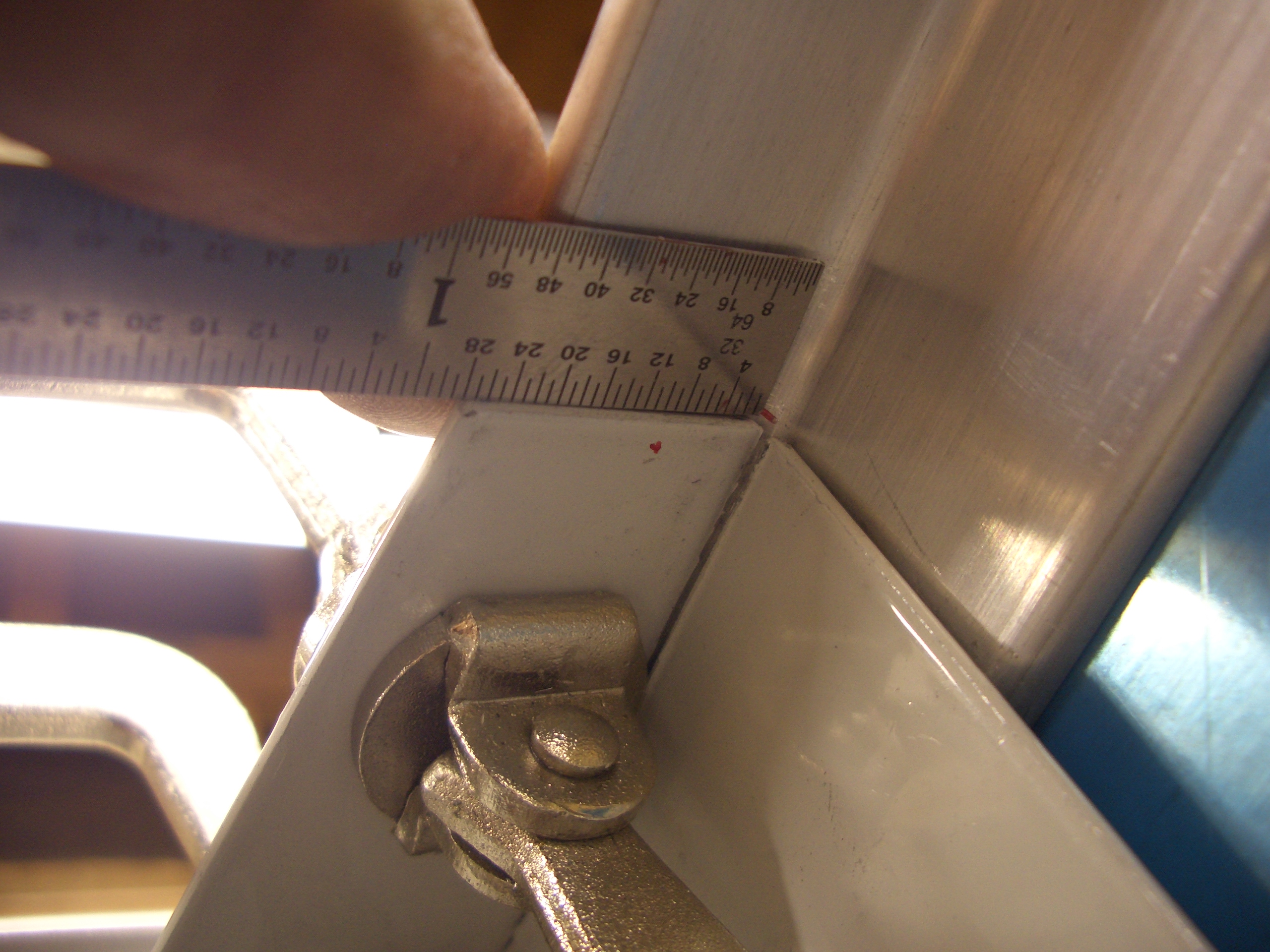
As I mentioned yesterday, the longerons have to be cut back 3/4″ from the firewall.  I marked this dimension and then cut it off with a die grinder and cutoff disk and filed to the line.

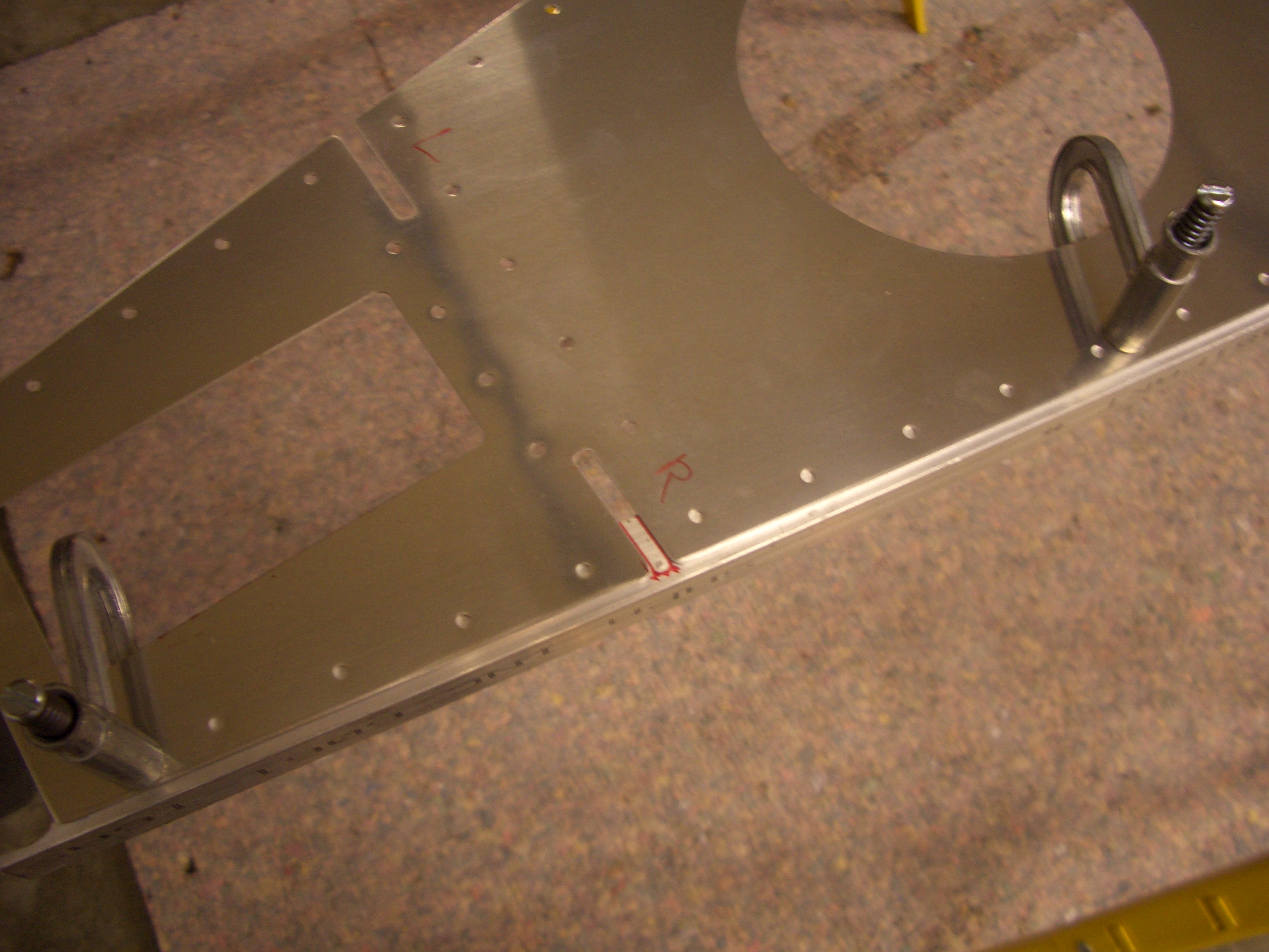
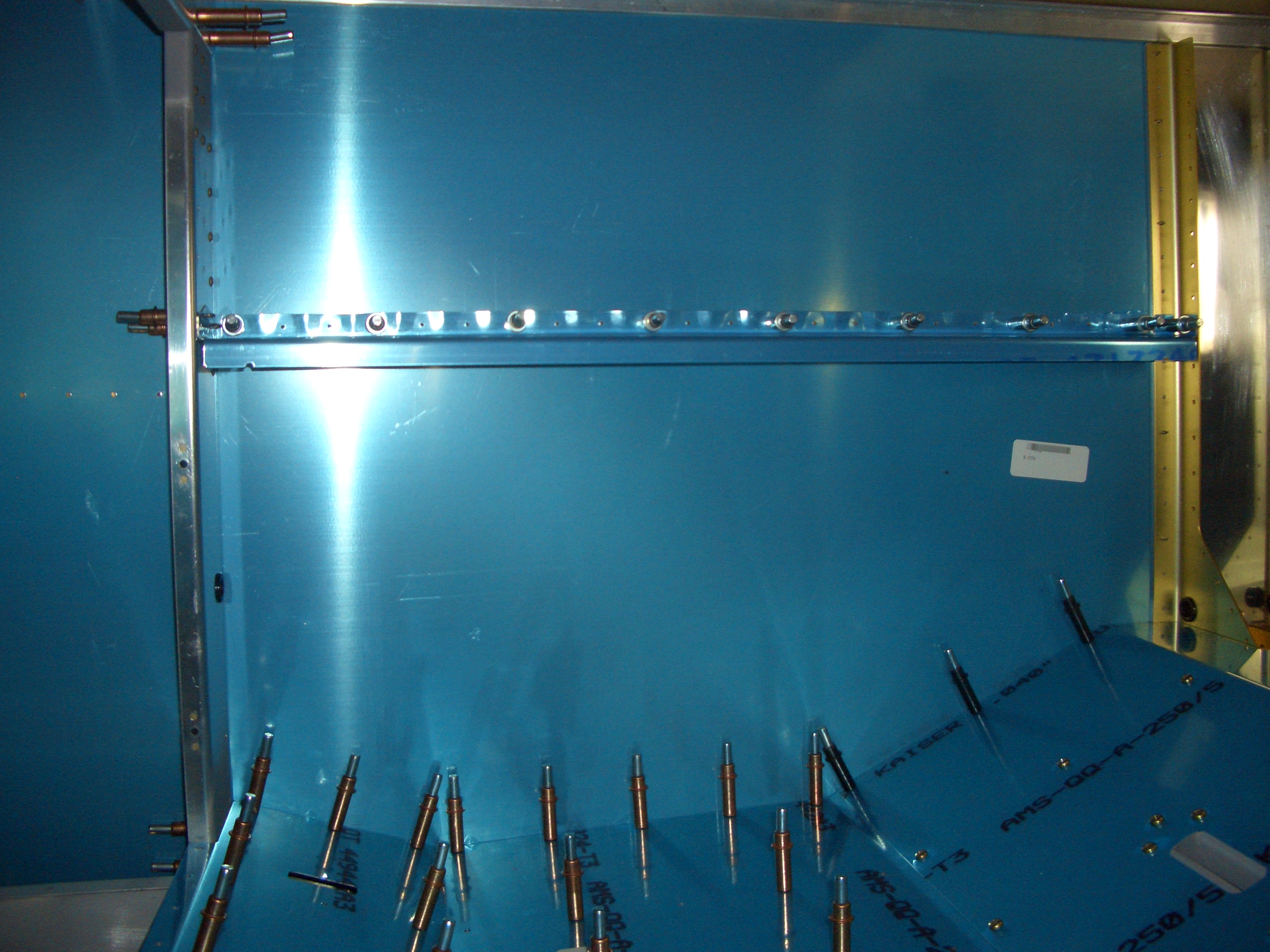
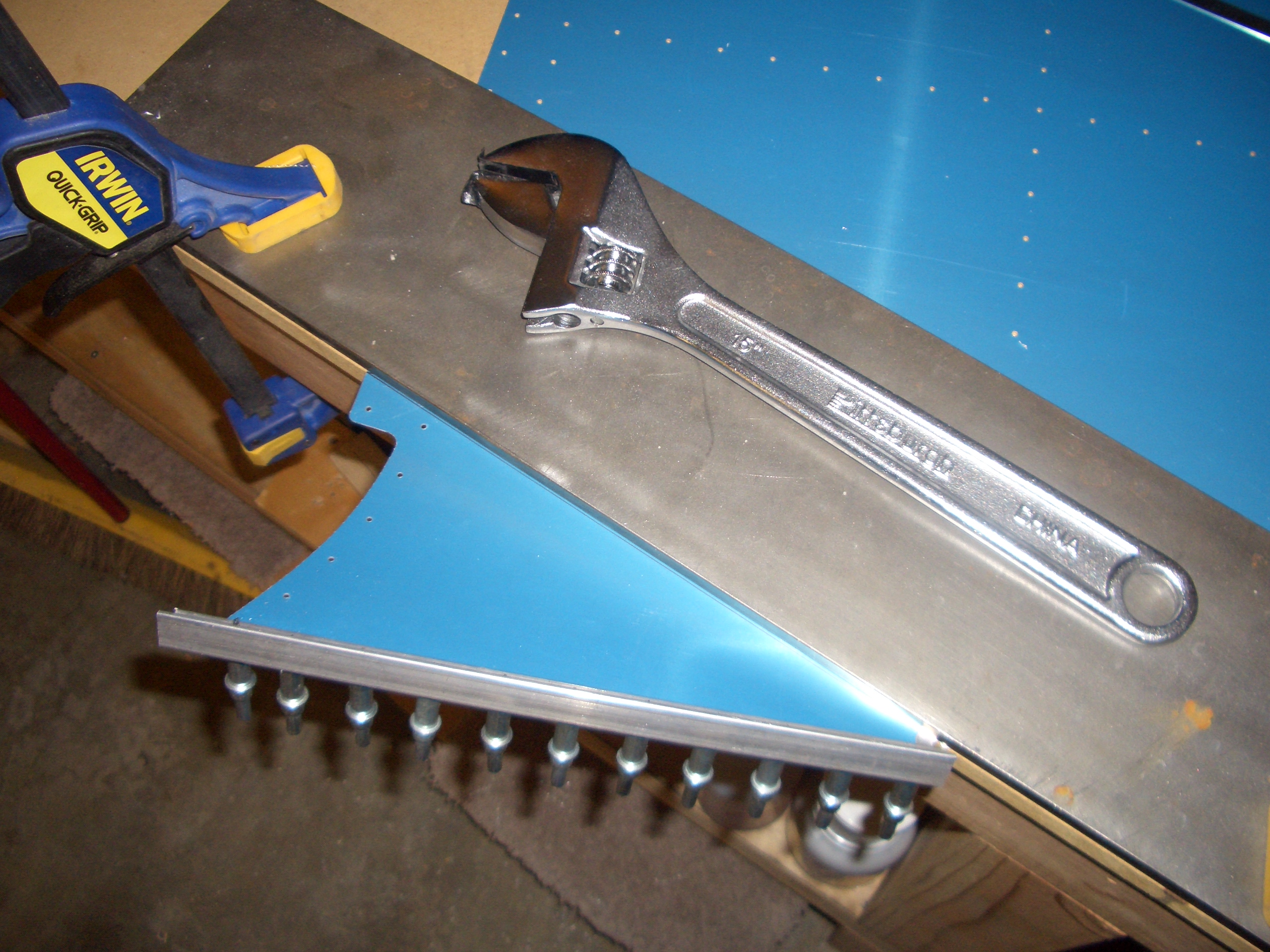
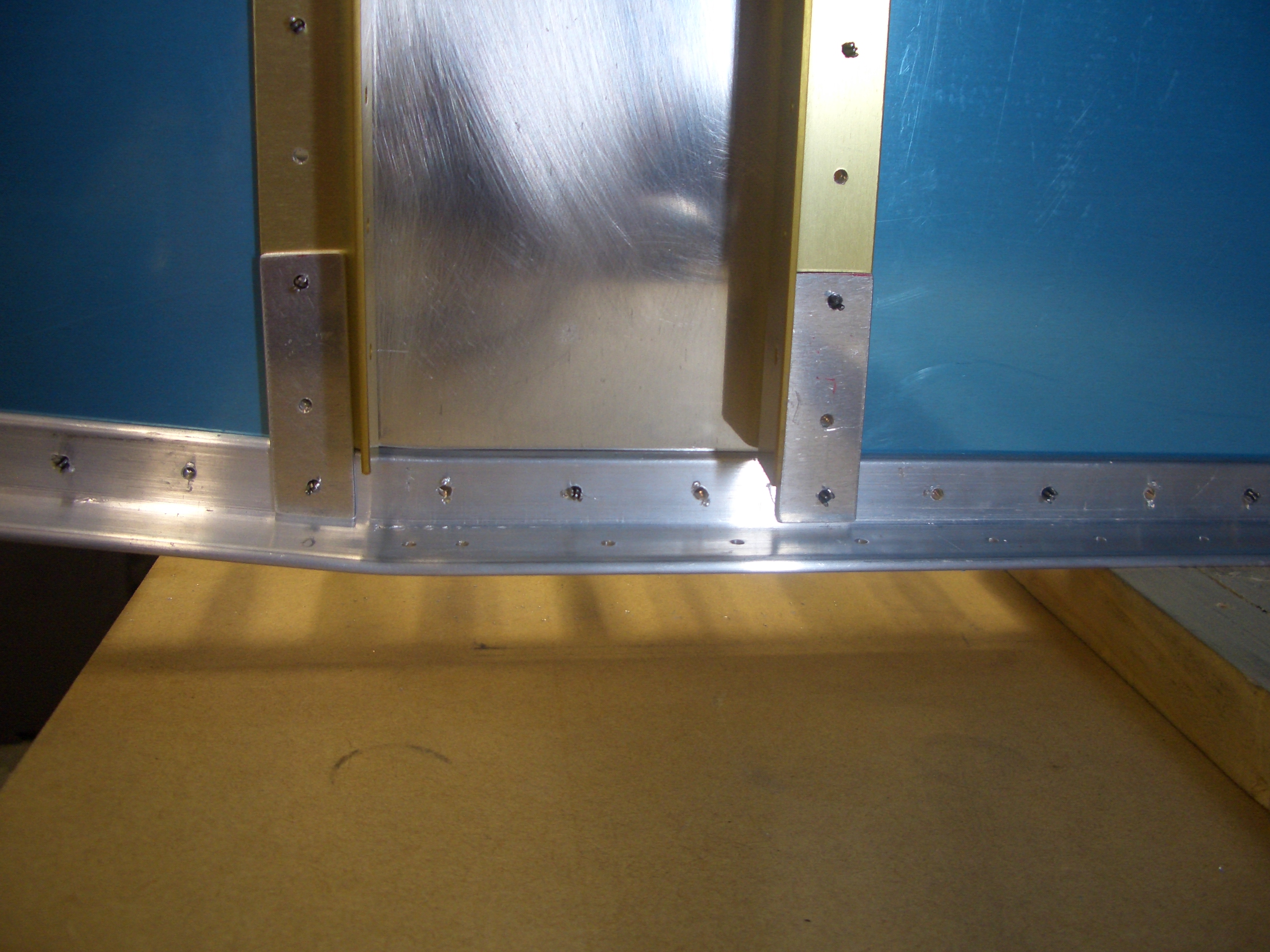
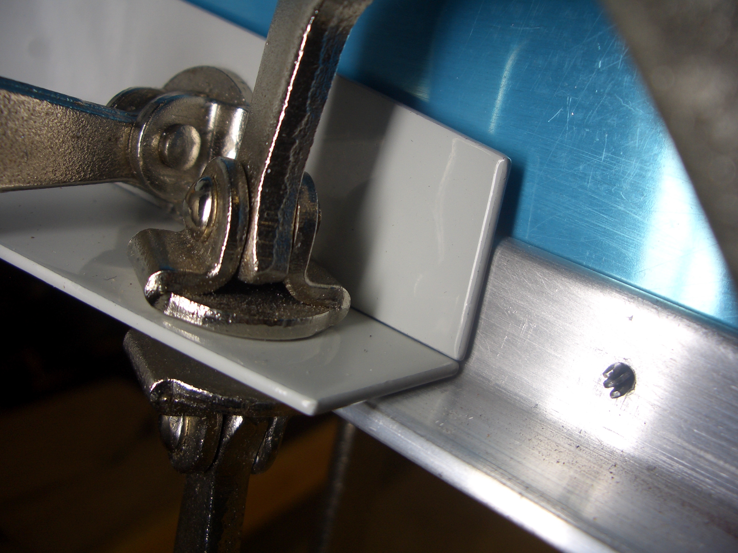
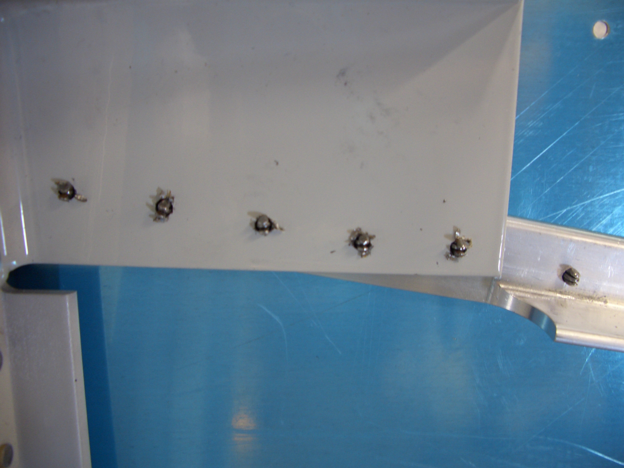
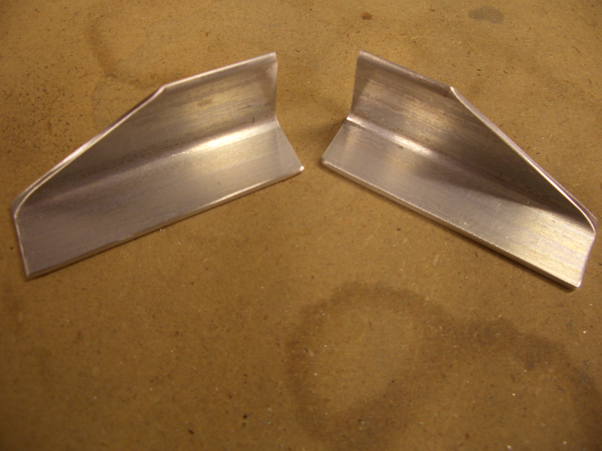
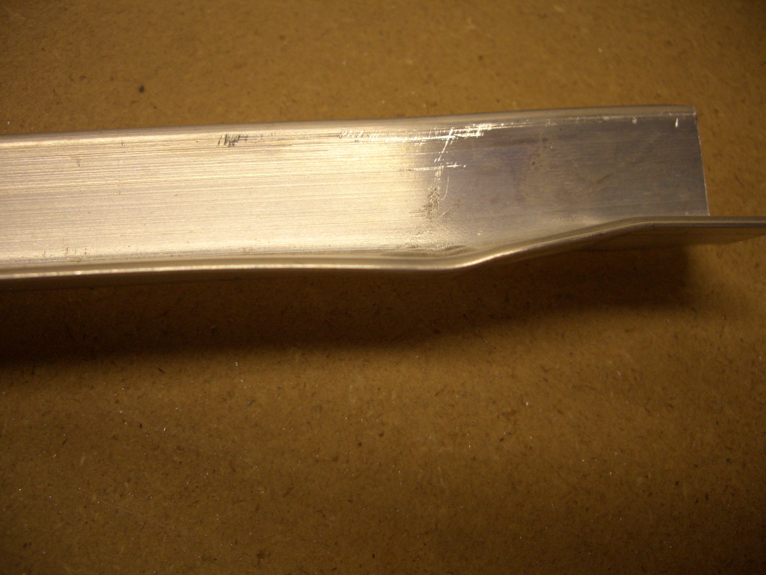
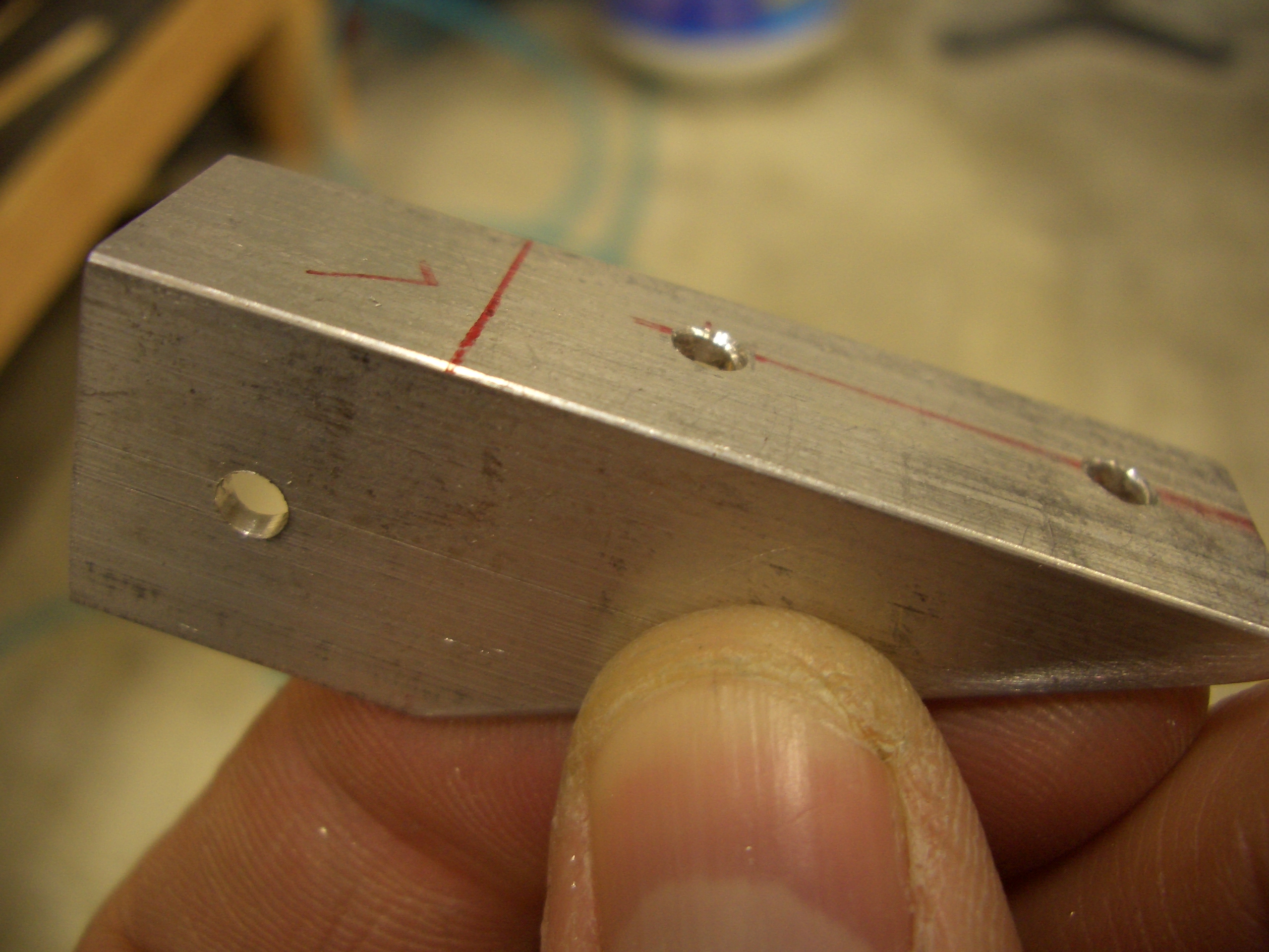
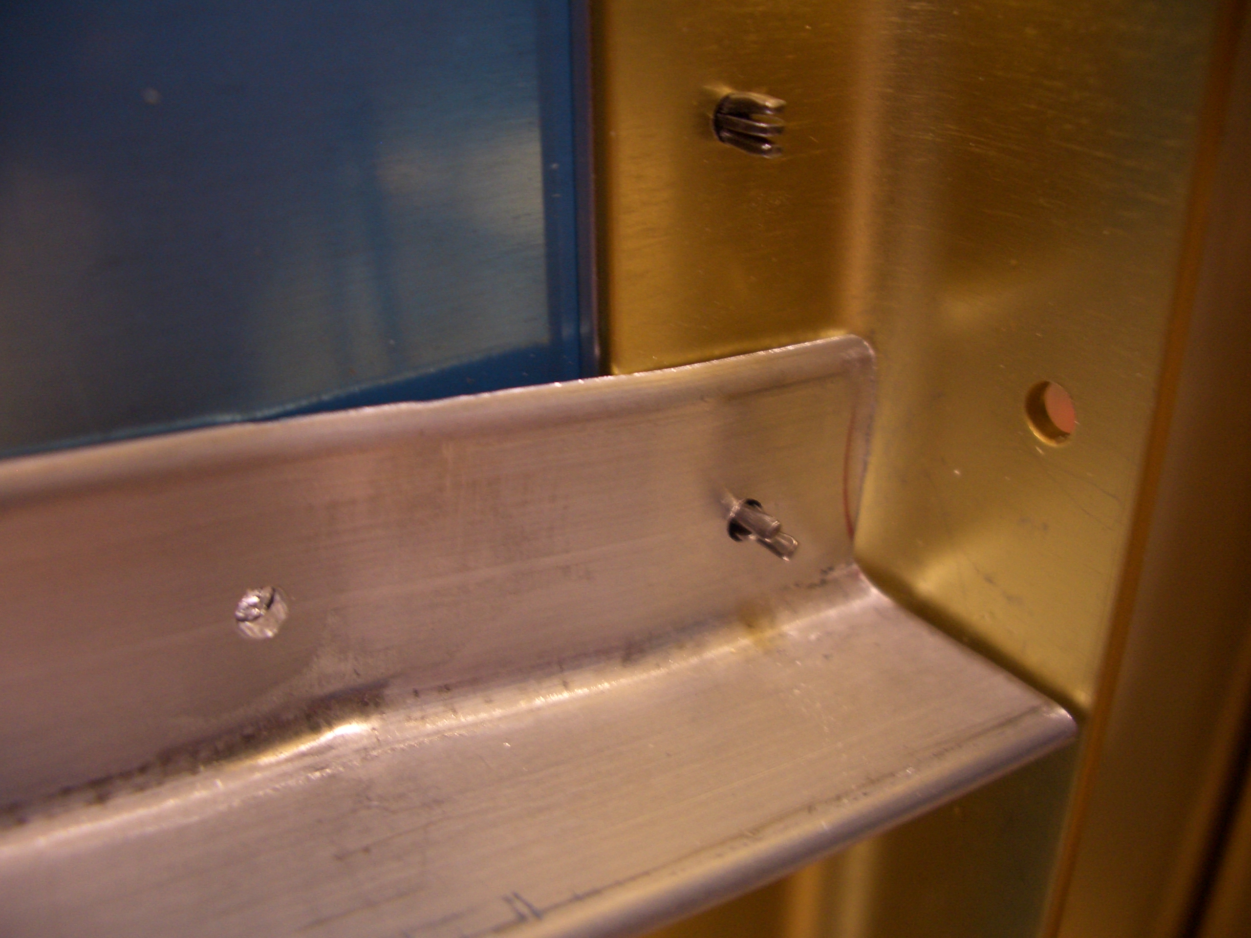
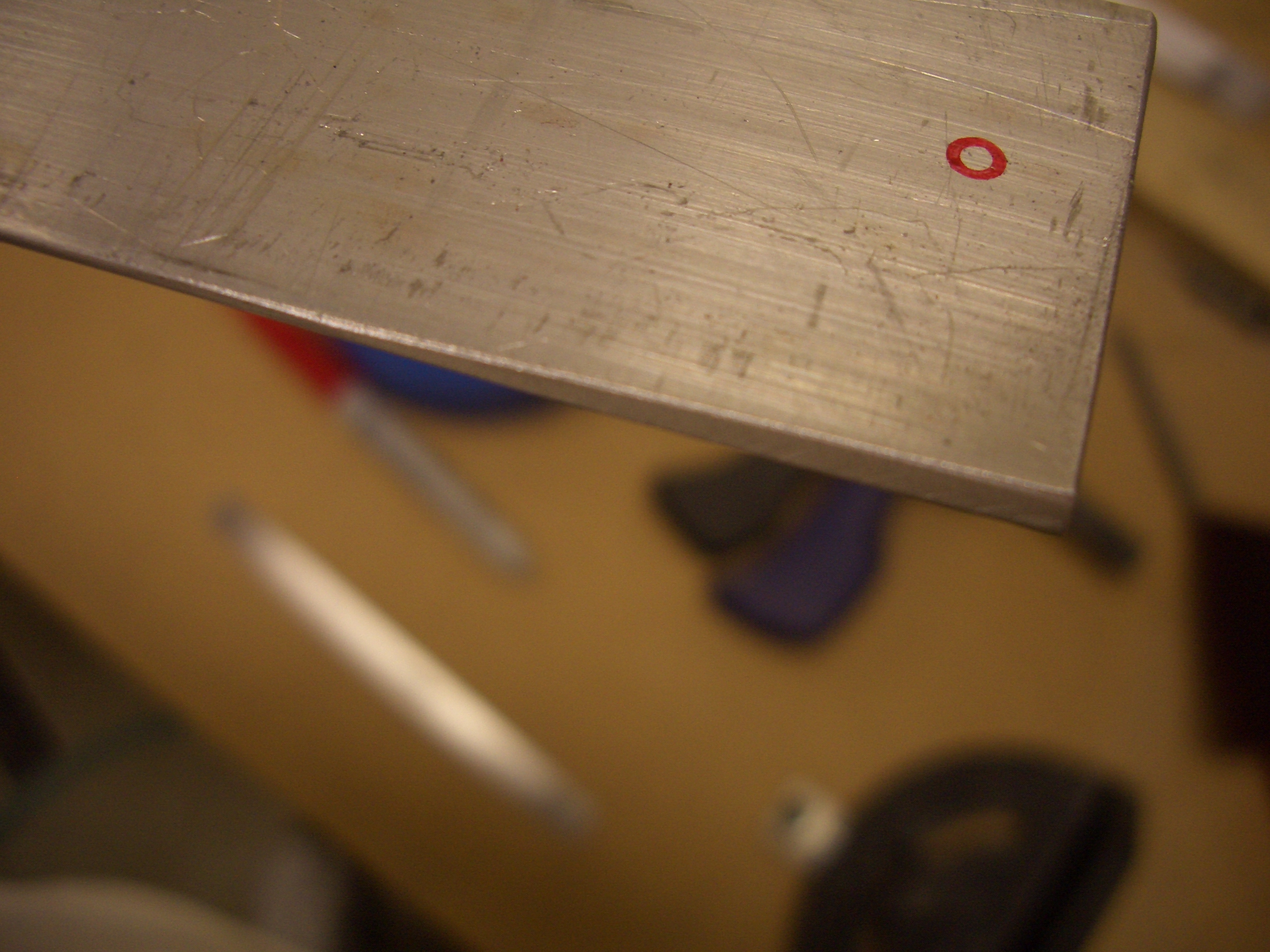
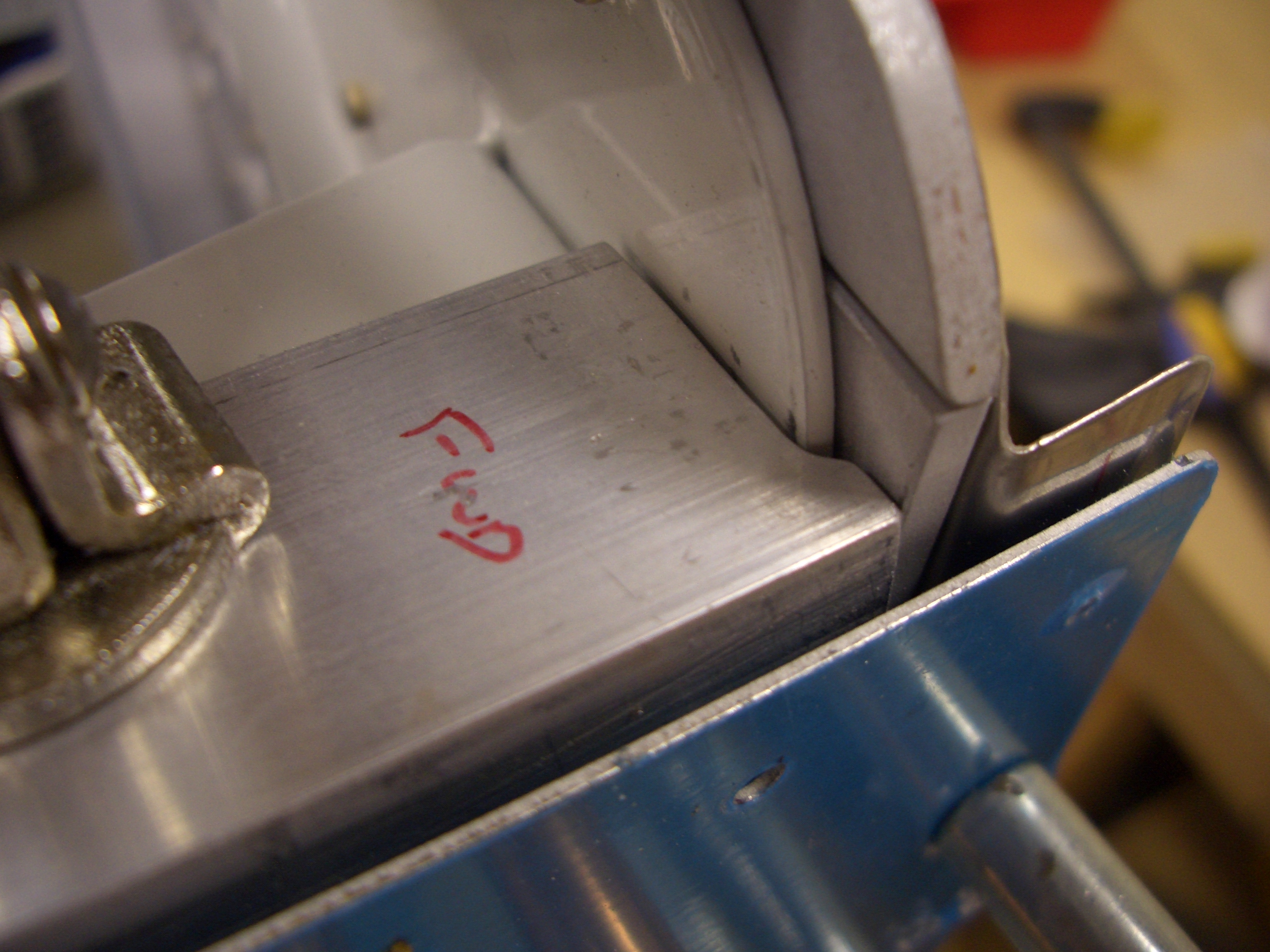
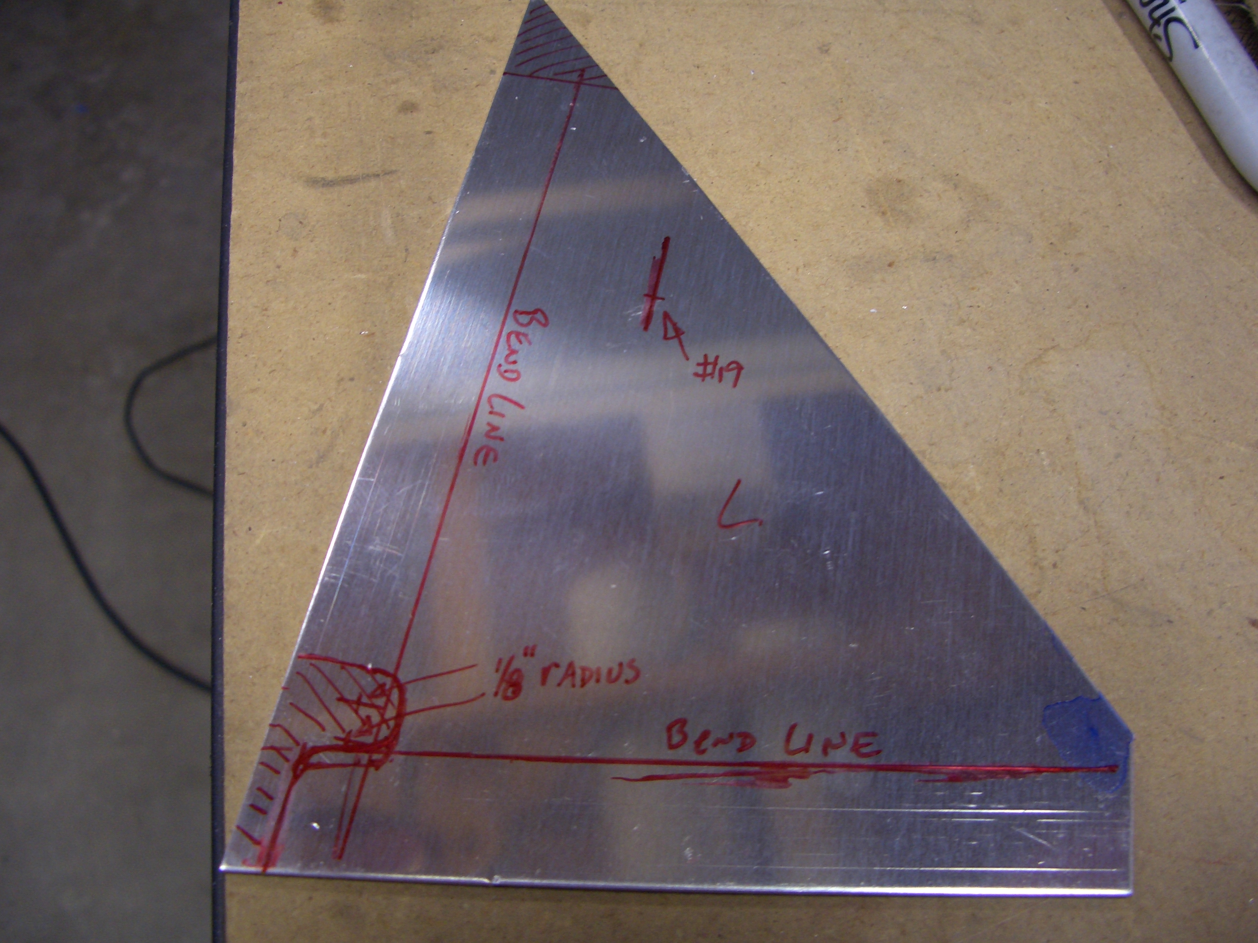
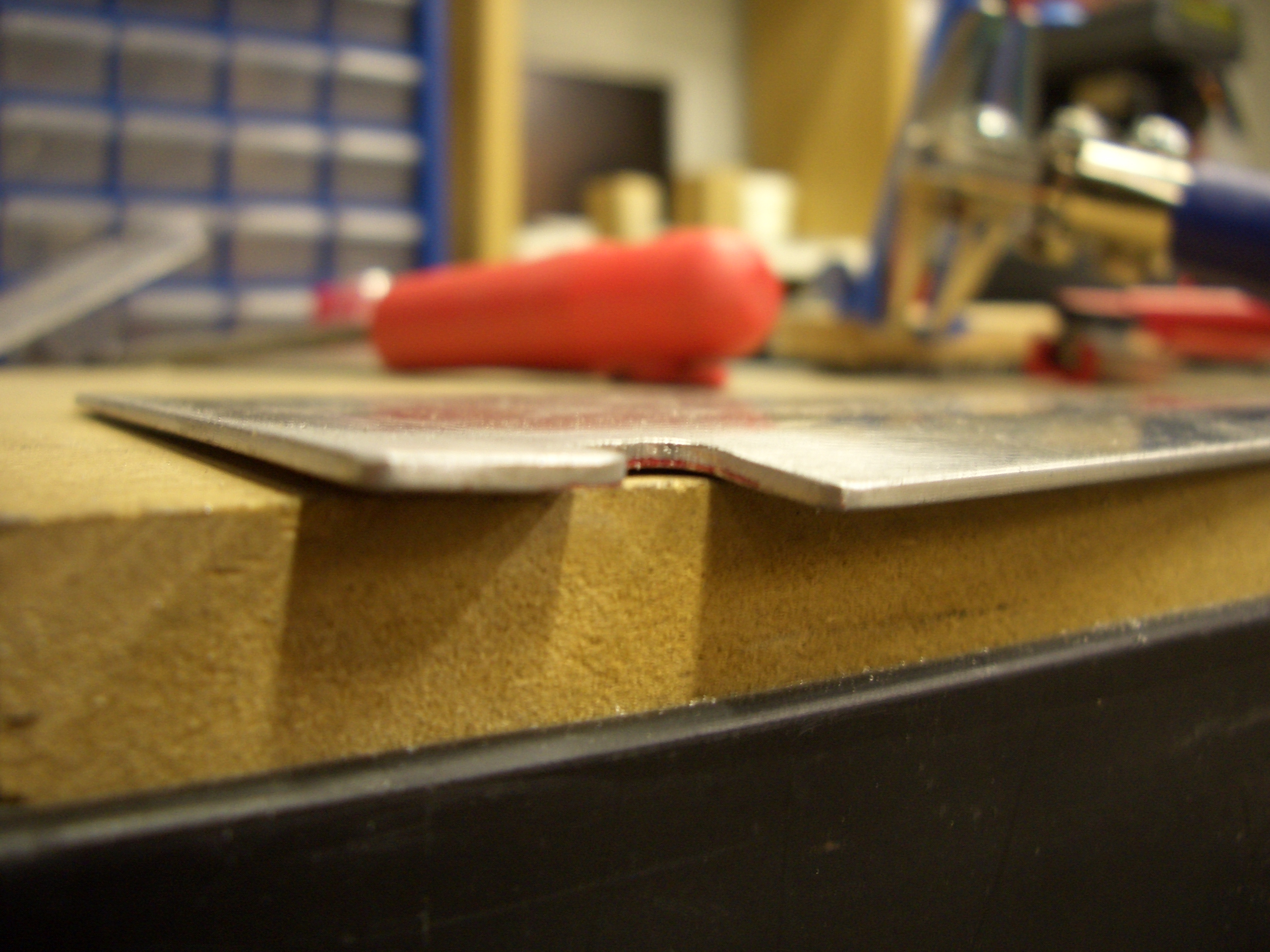
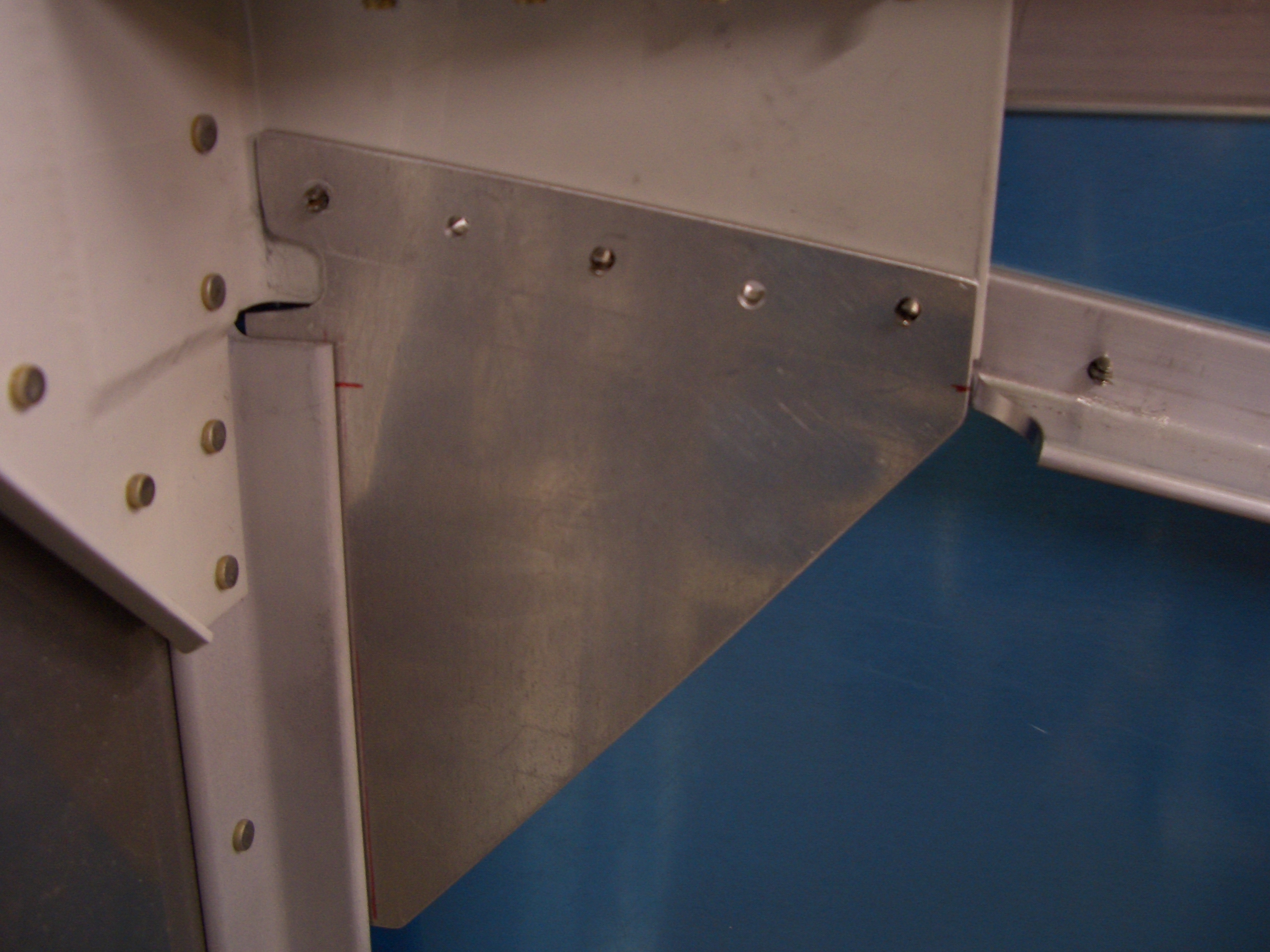
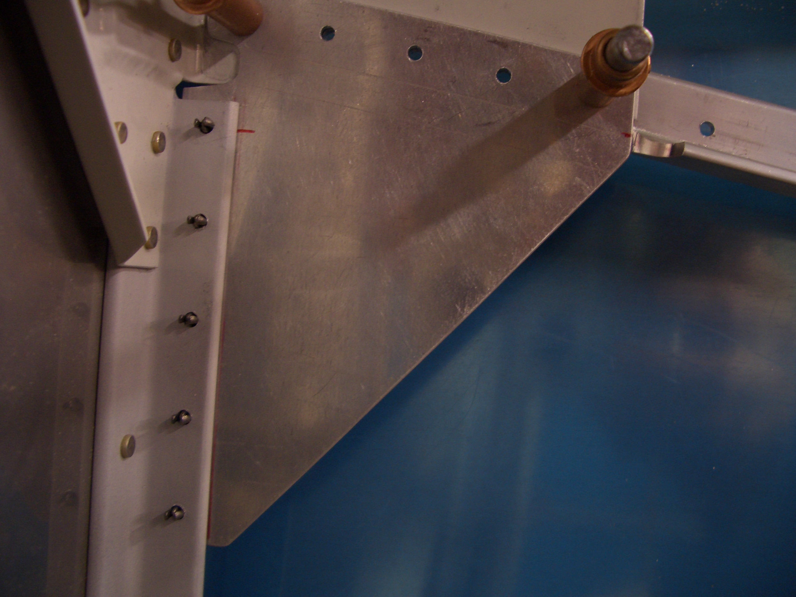
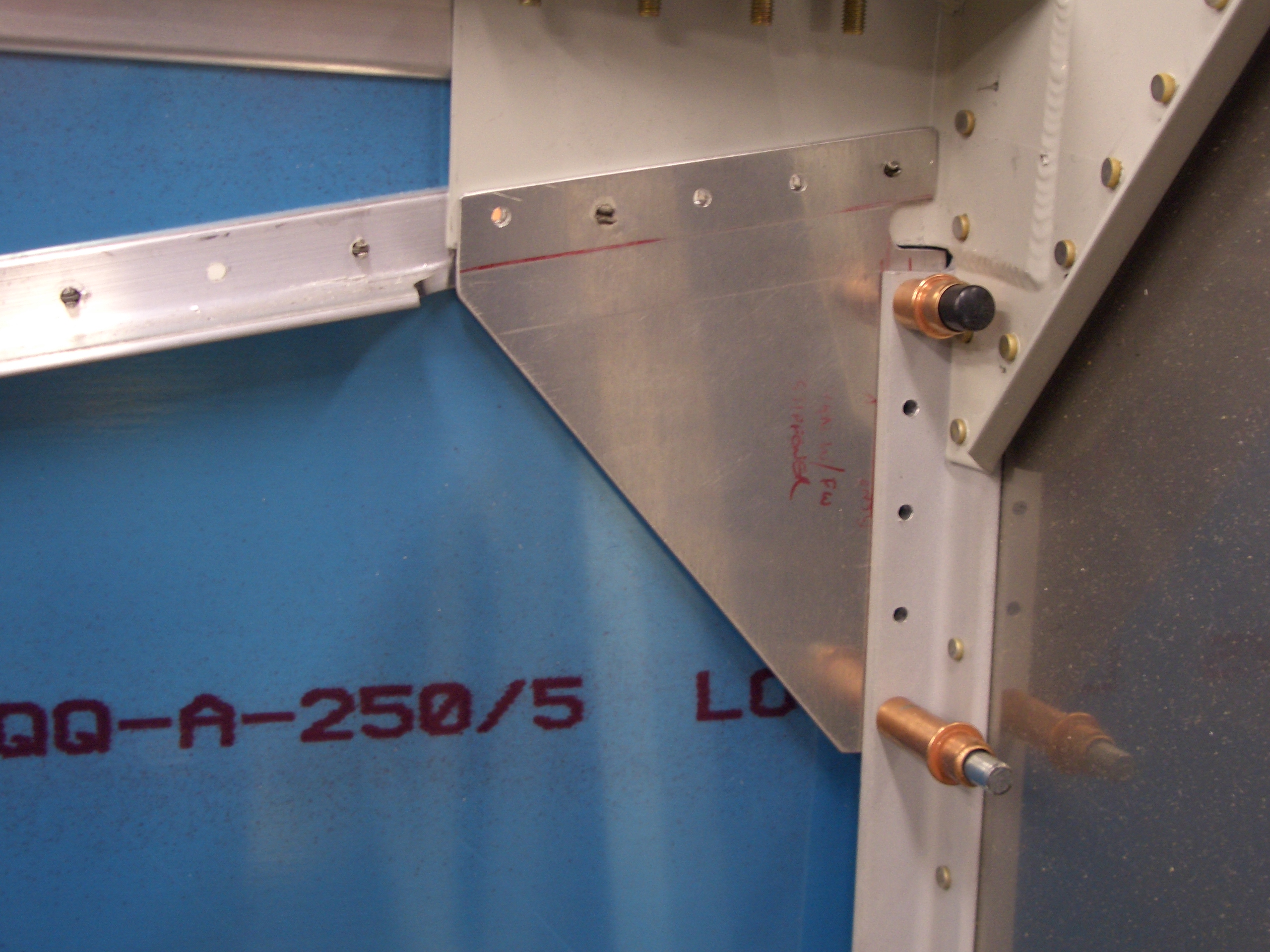
Two F-704 connector straps need to be fabricated out of 0.063 sheet.  The kit provides pieces the right thickness and width, but too long.  Cutting them to the dimensions listed on the plans first will mean you have to get them positioned precisely to ensure adequate edge distance on each end.  Instead, I match drilled them to the structure first and then cut off the long end to ensure sufficient edge distance.

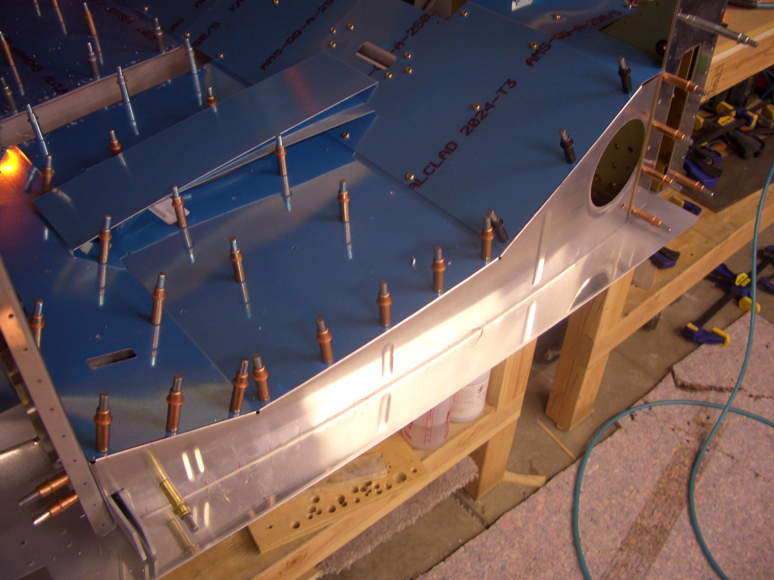
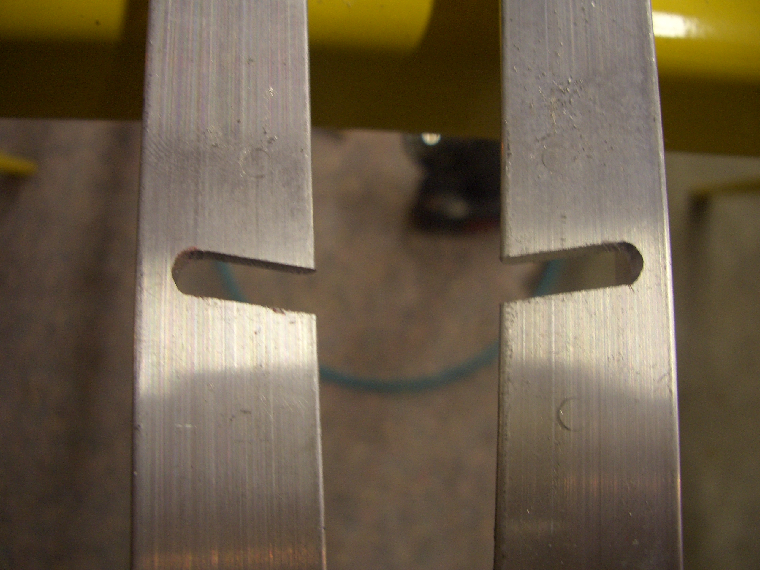
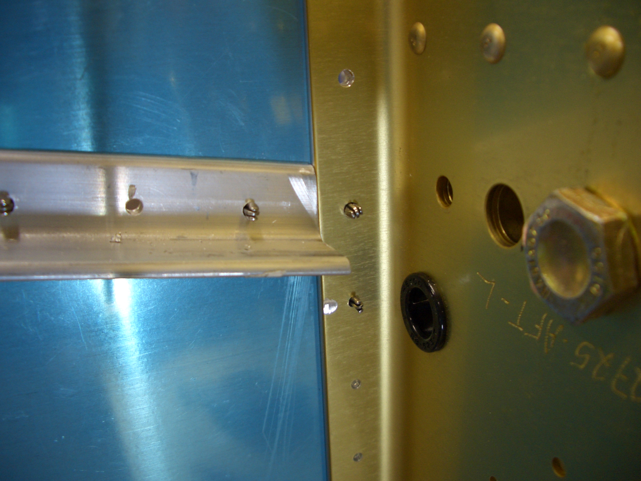
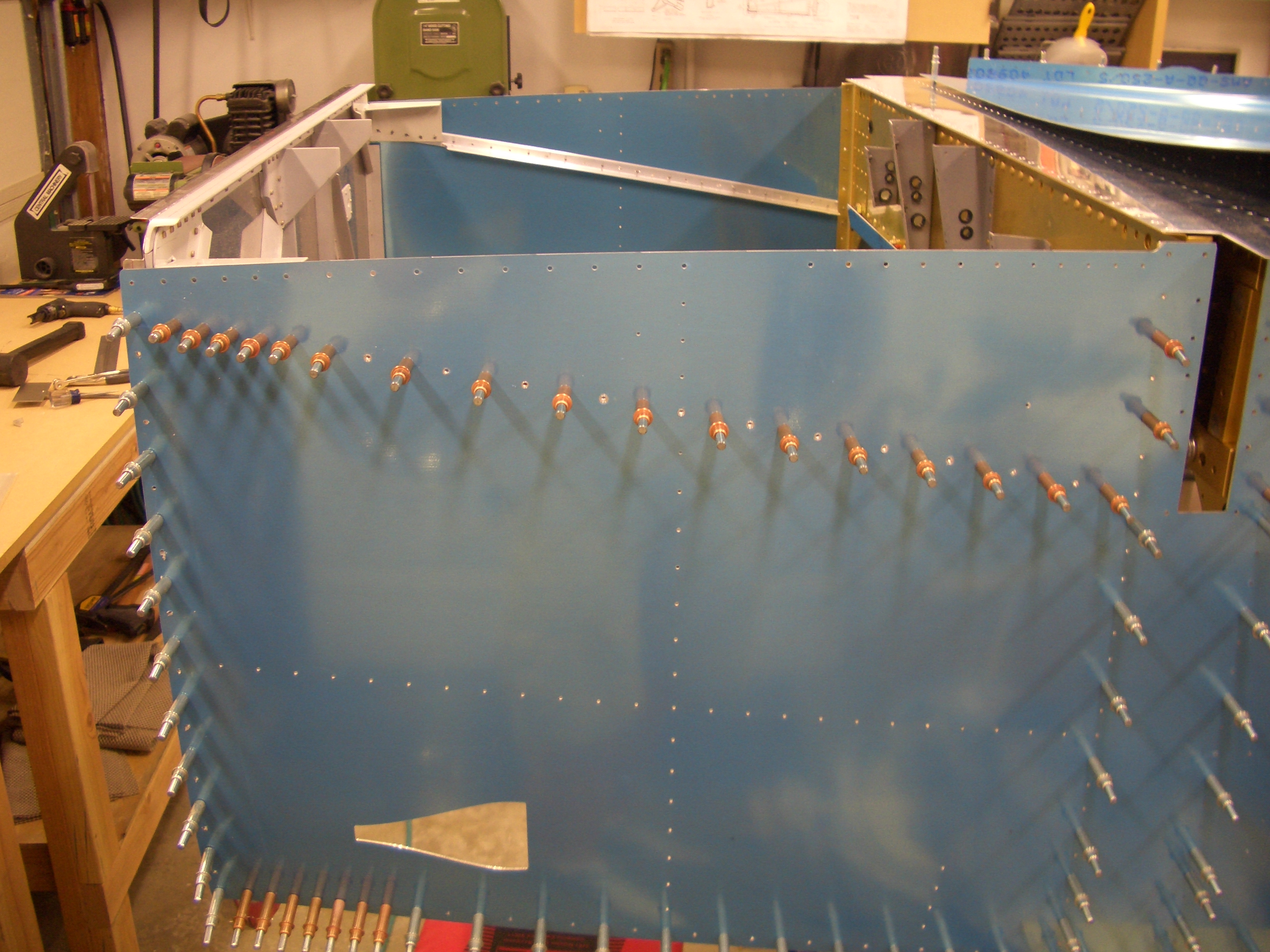
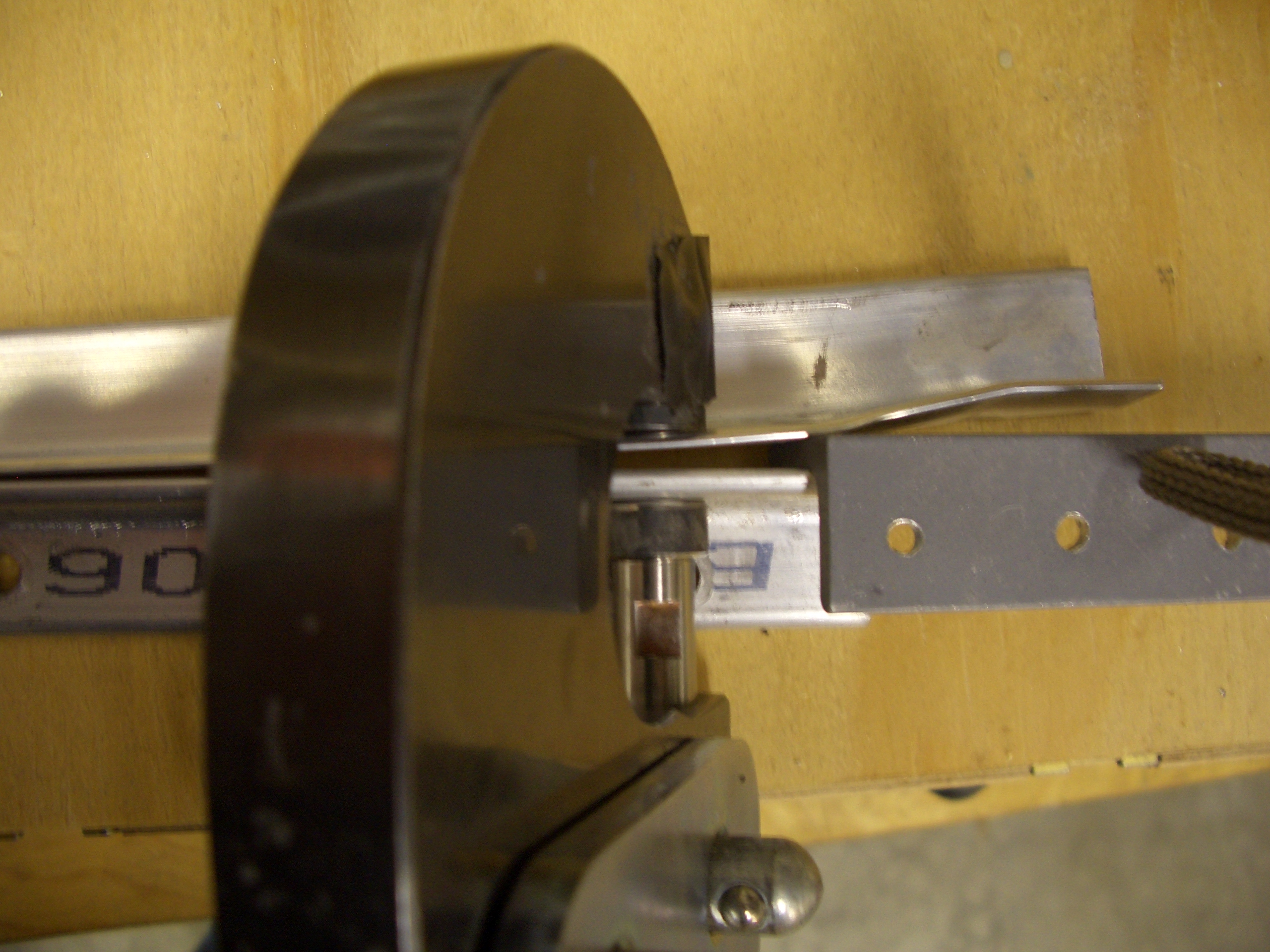
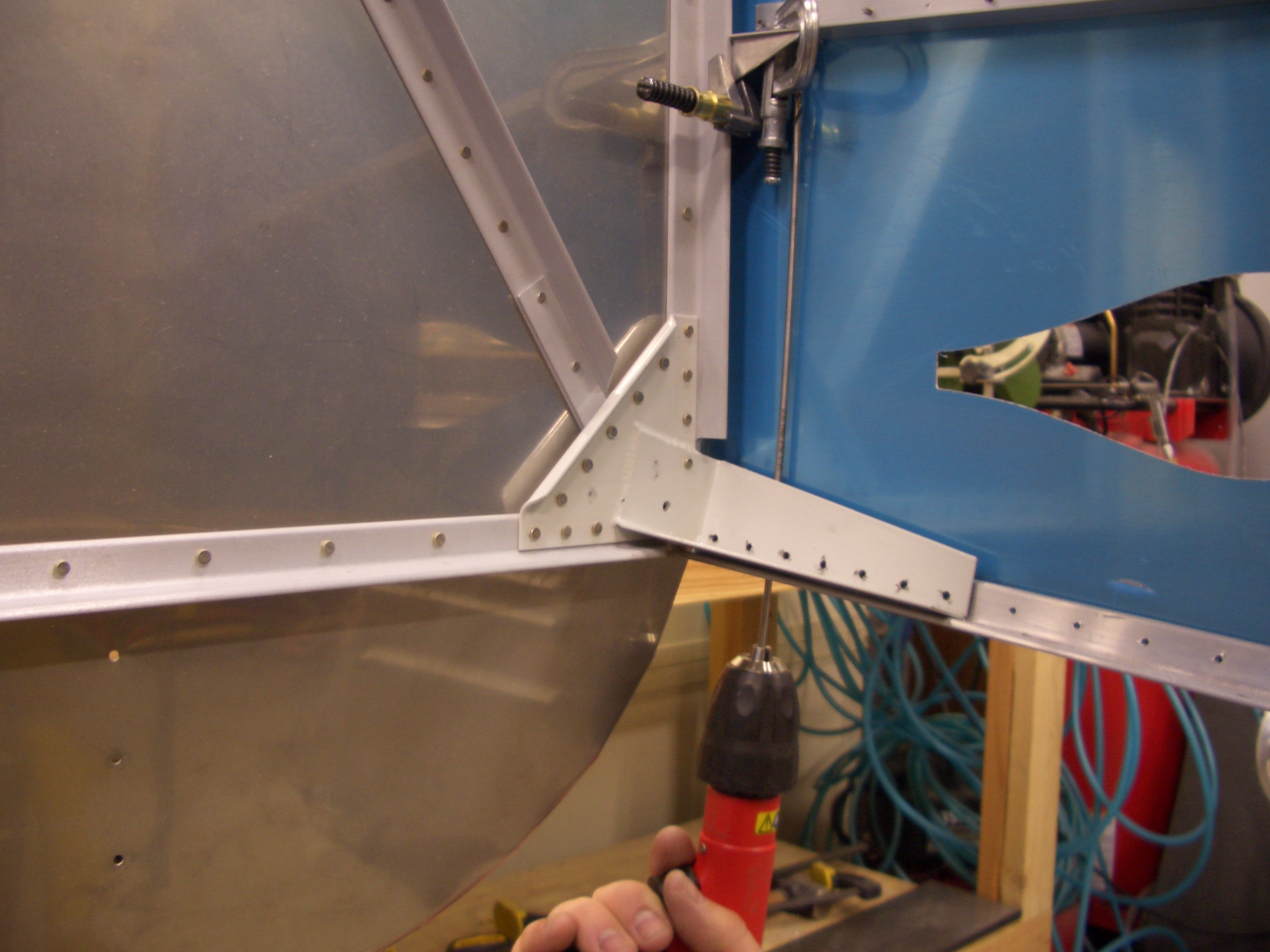
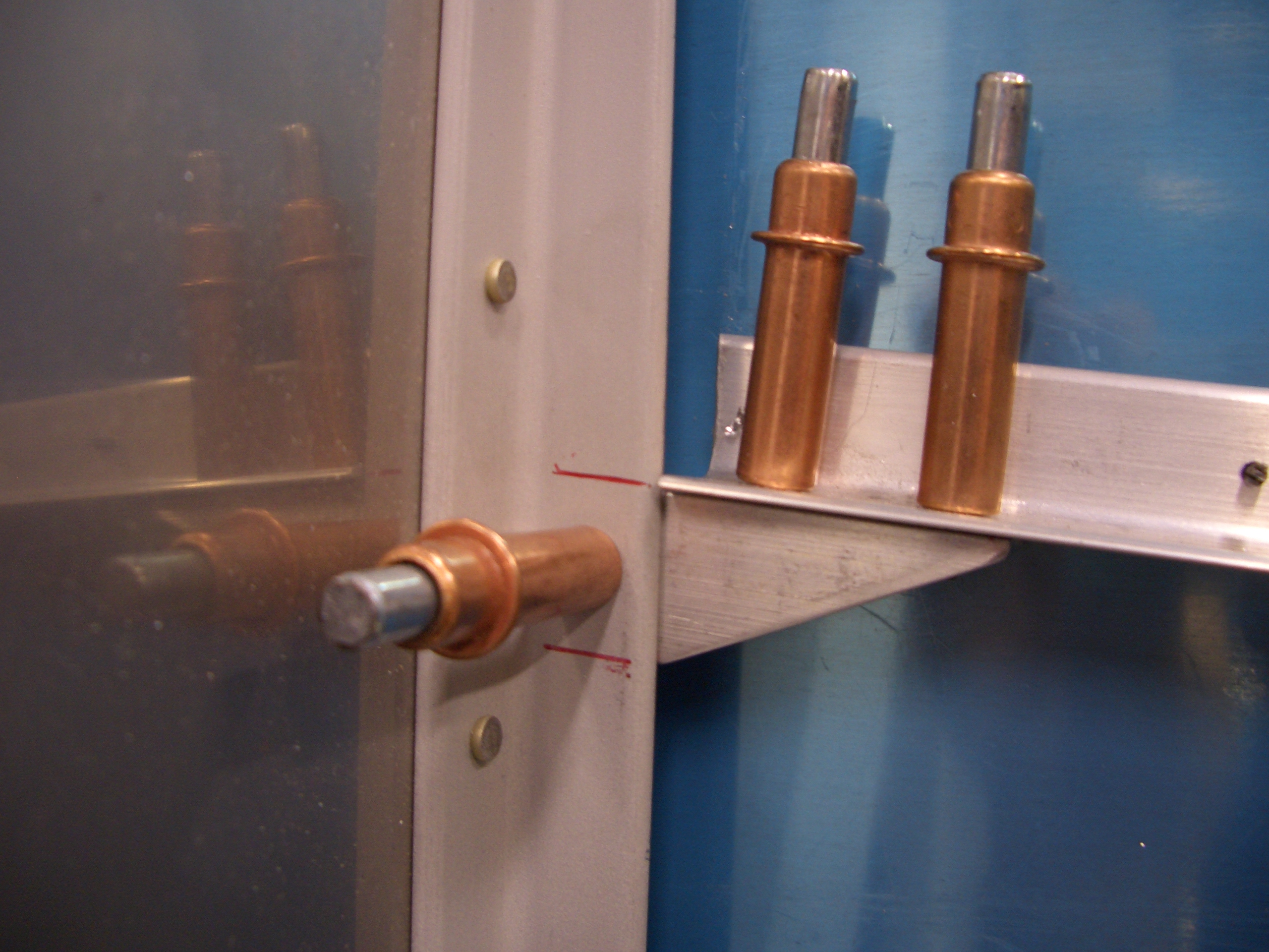
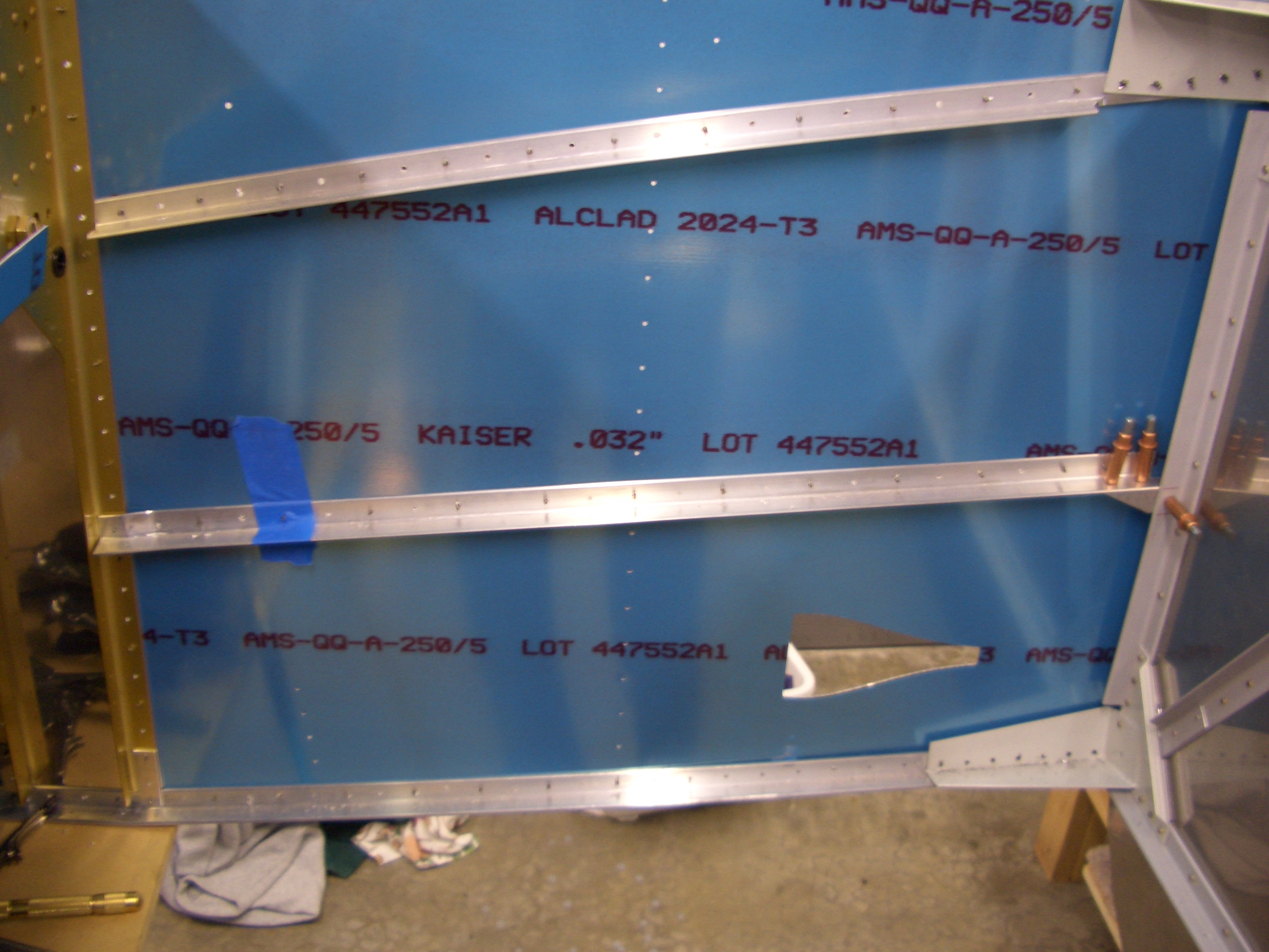
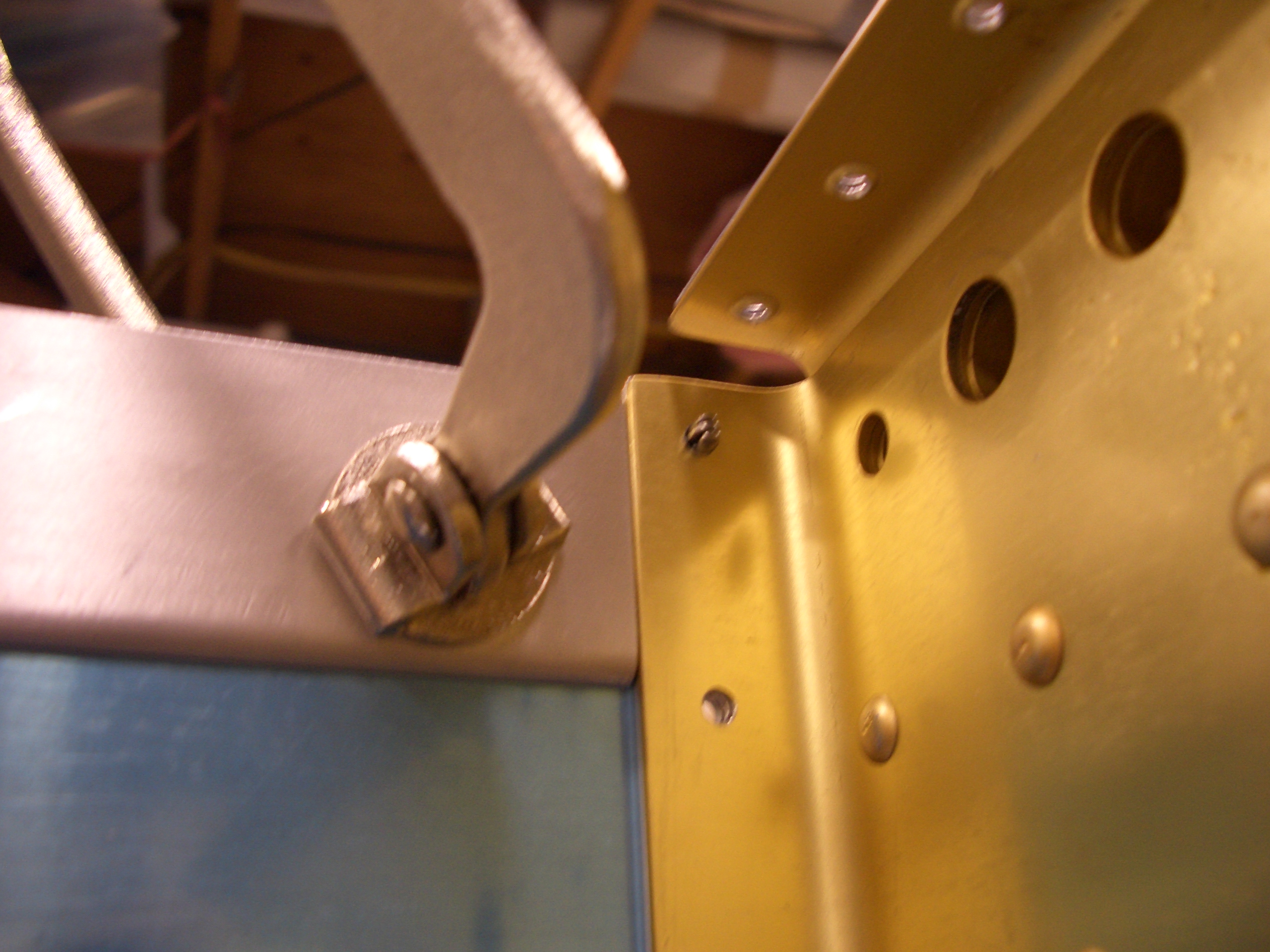
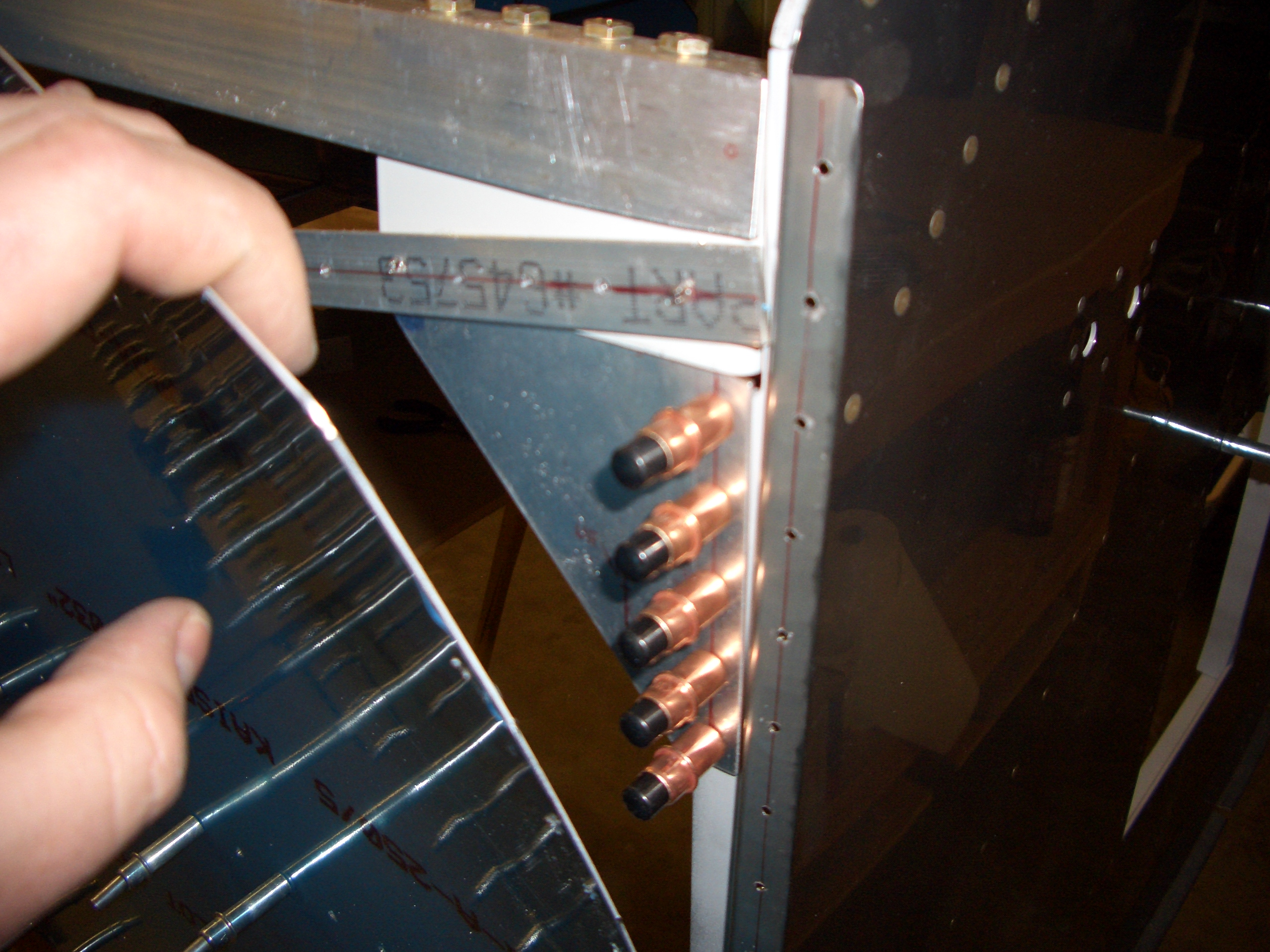
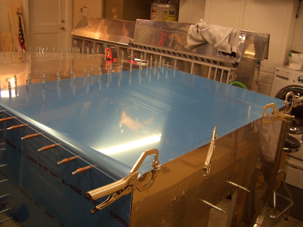
Where the engine mounts on the firewall nestle inside the longerons, clecos would interfere.  You can’t just leave the holes empty though since the weight of the firewall would cause the longerons to sag.  Fill these with some short AD470AD4 rivets (just sitting loose, not set) to ensure this doesn’t happen.  I put a piece of tape over this to ensure they don’t fall out.

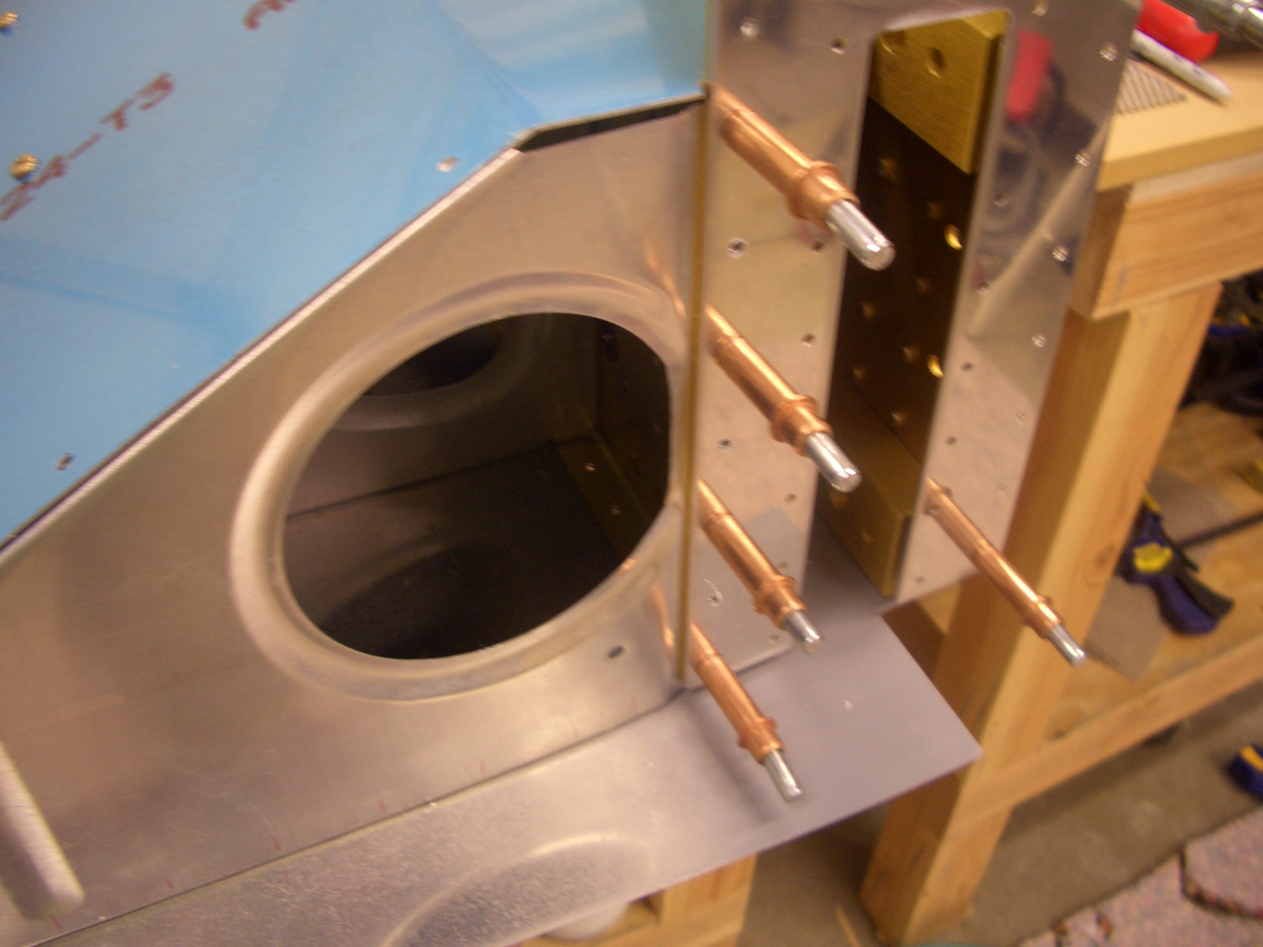
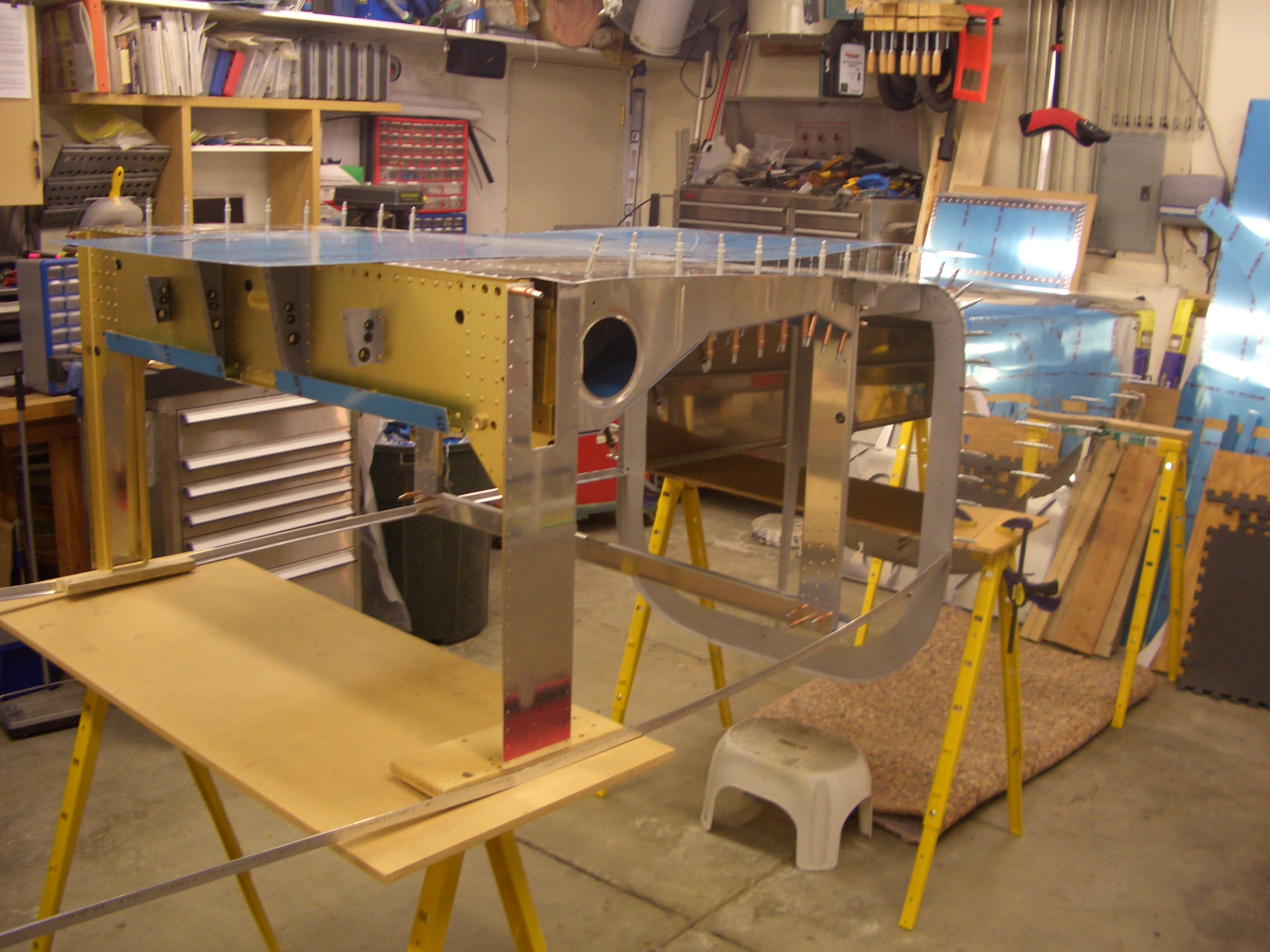
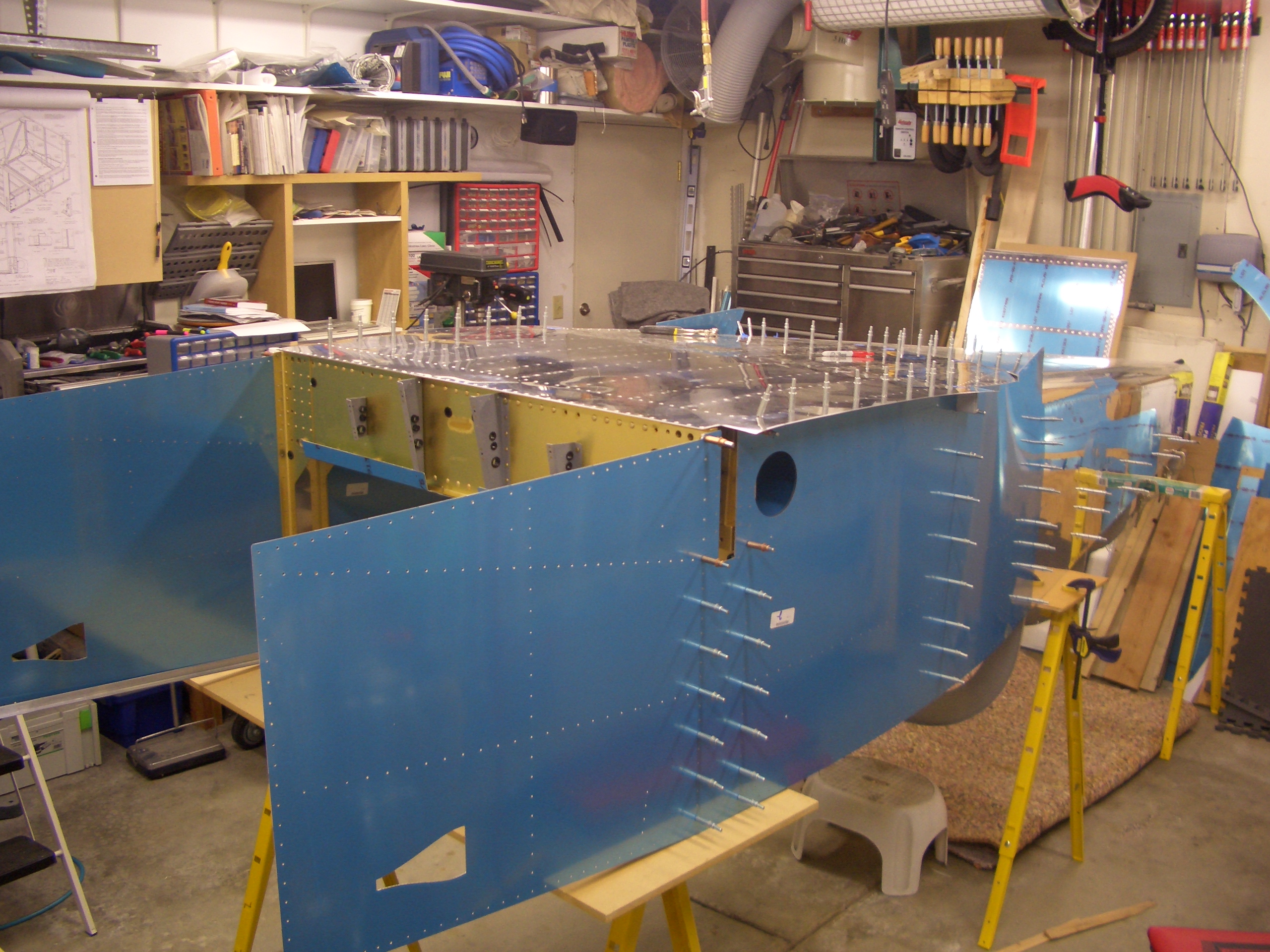
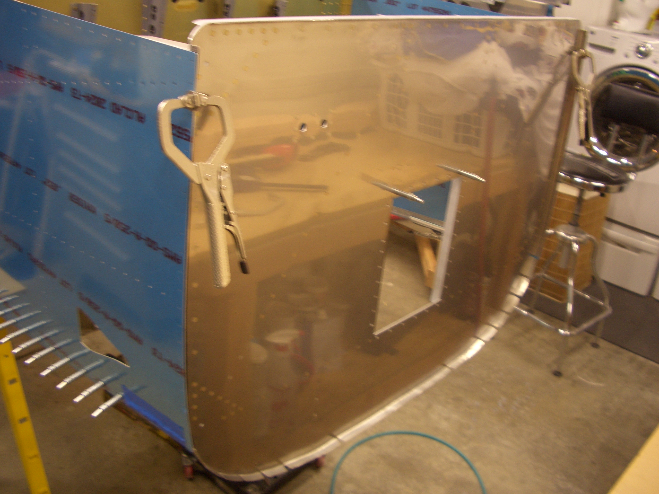
Next, the firewall is set in position to check for correct setback from the side skins.  I had to take this off a couple of times to file back areas where the ends of the longerons were interfering with the firewall stiffeners.

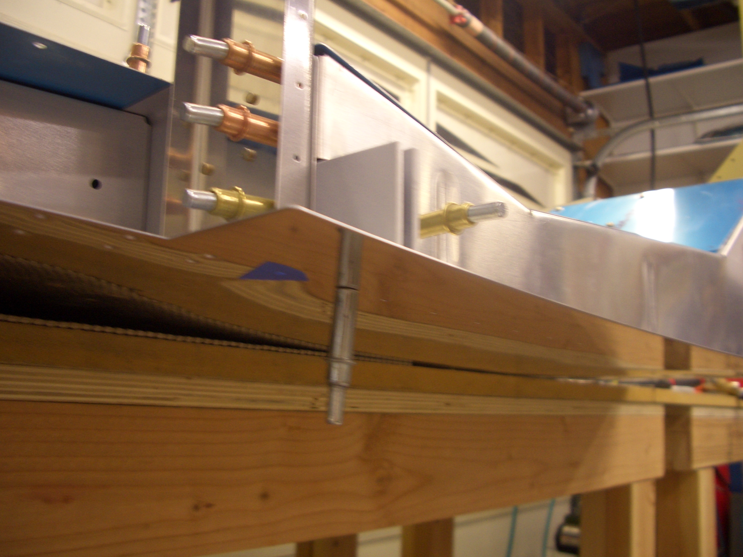
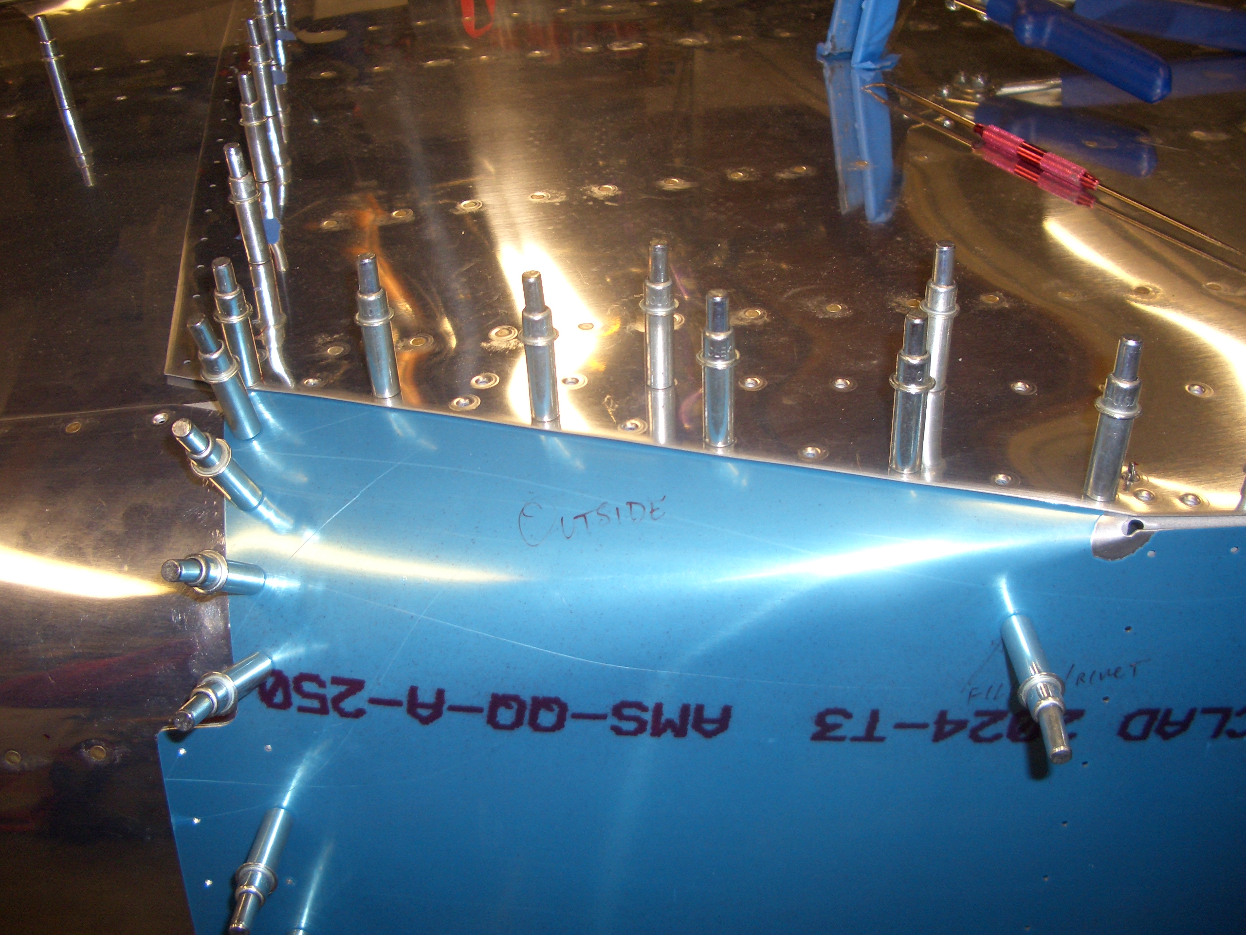
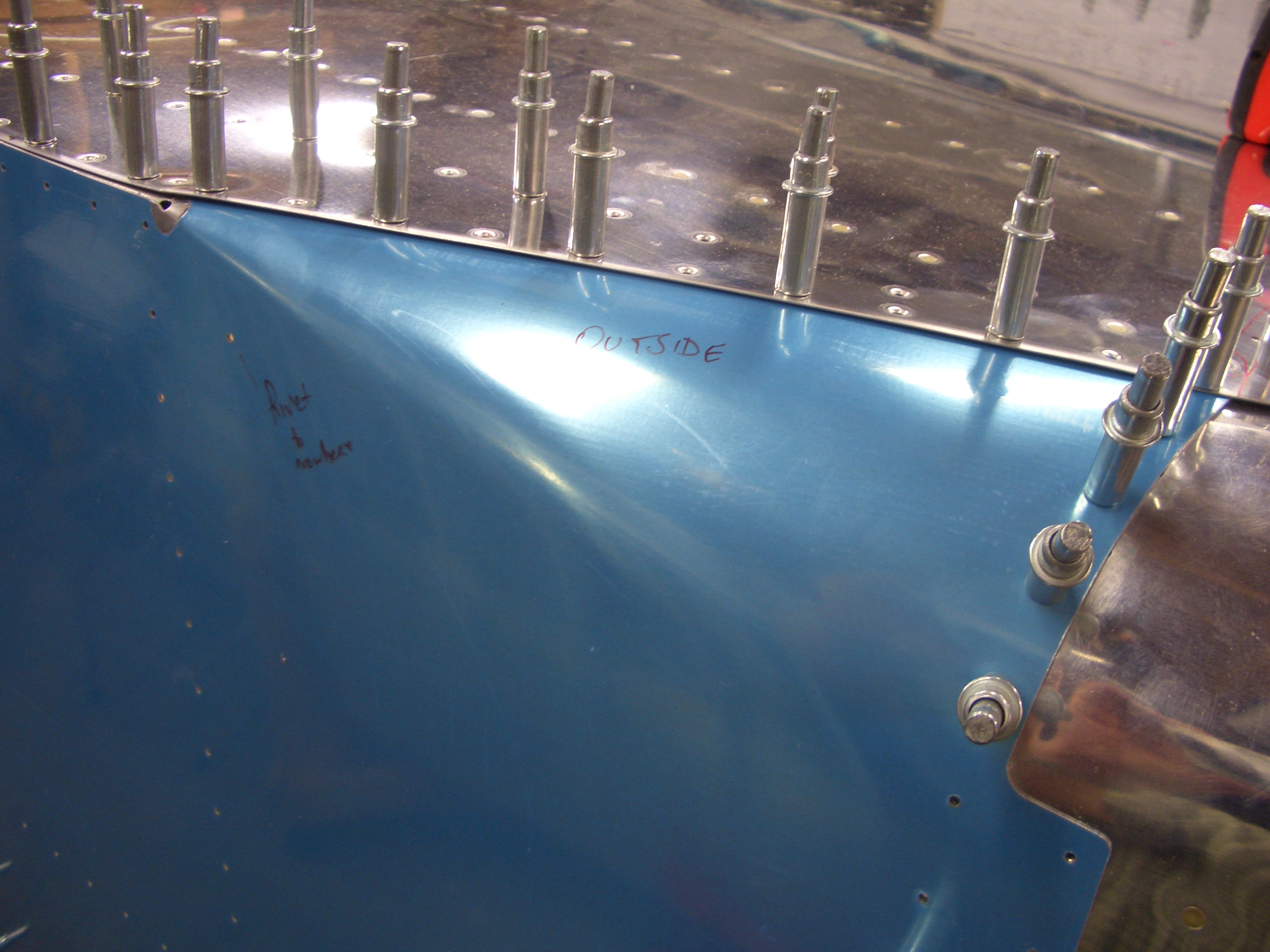
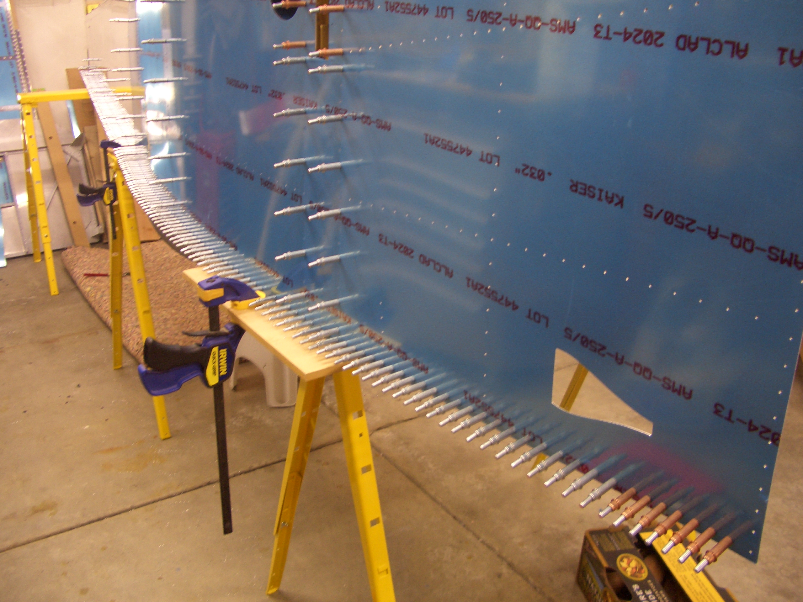
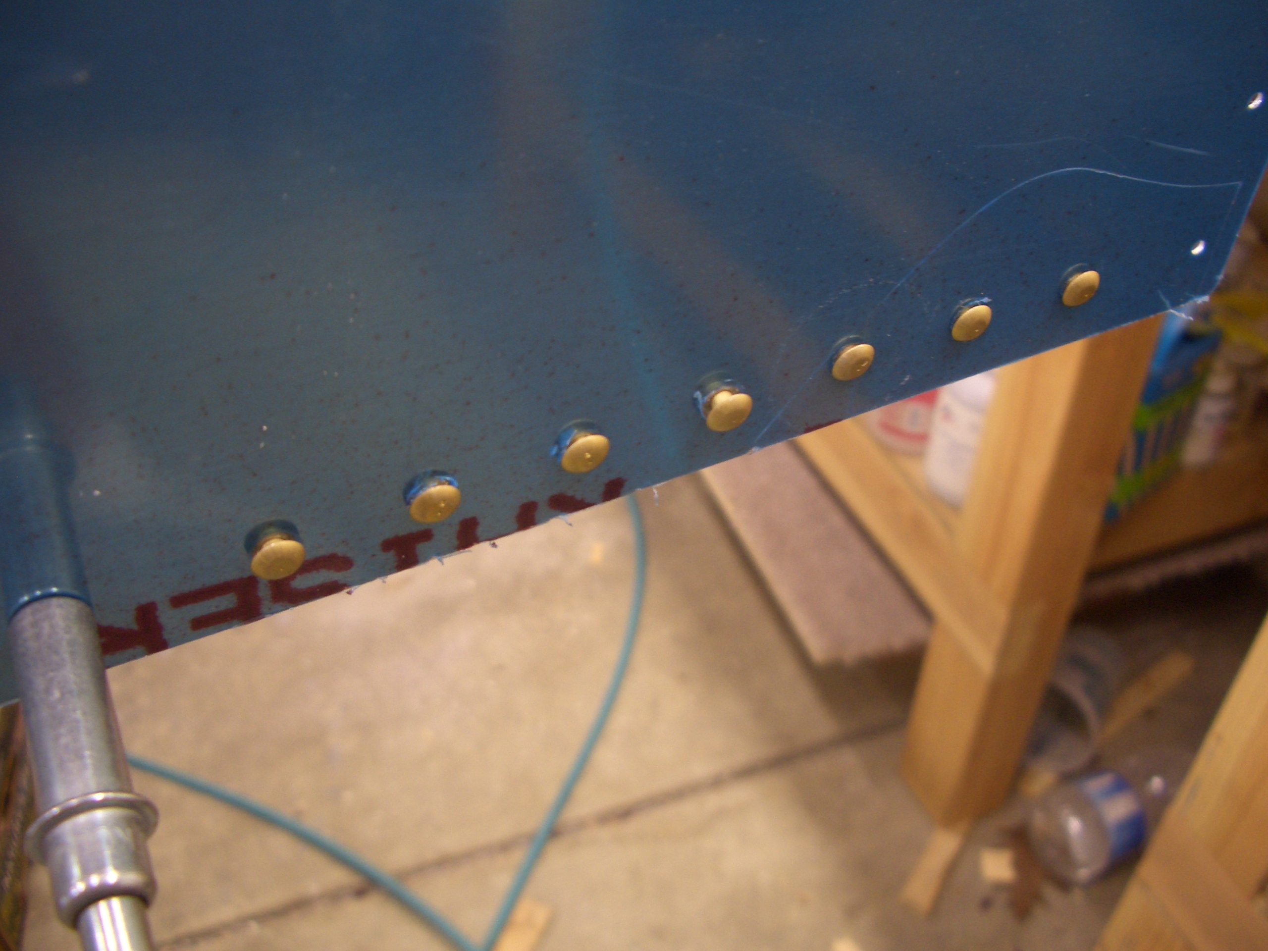
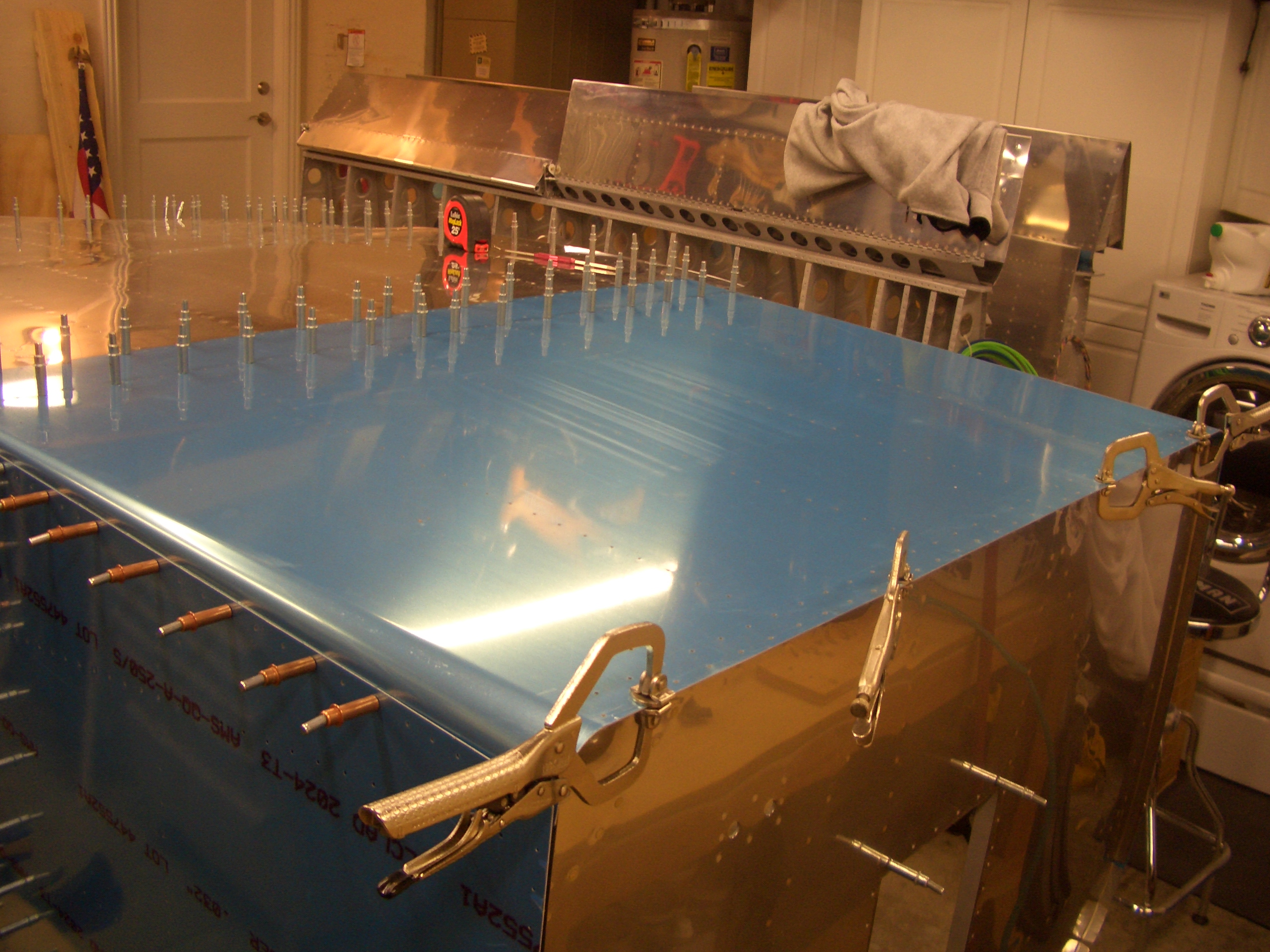
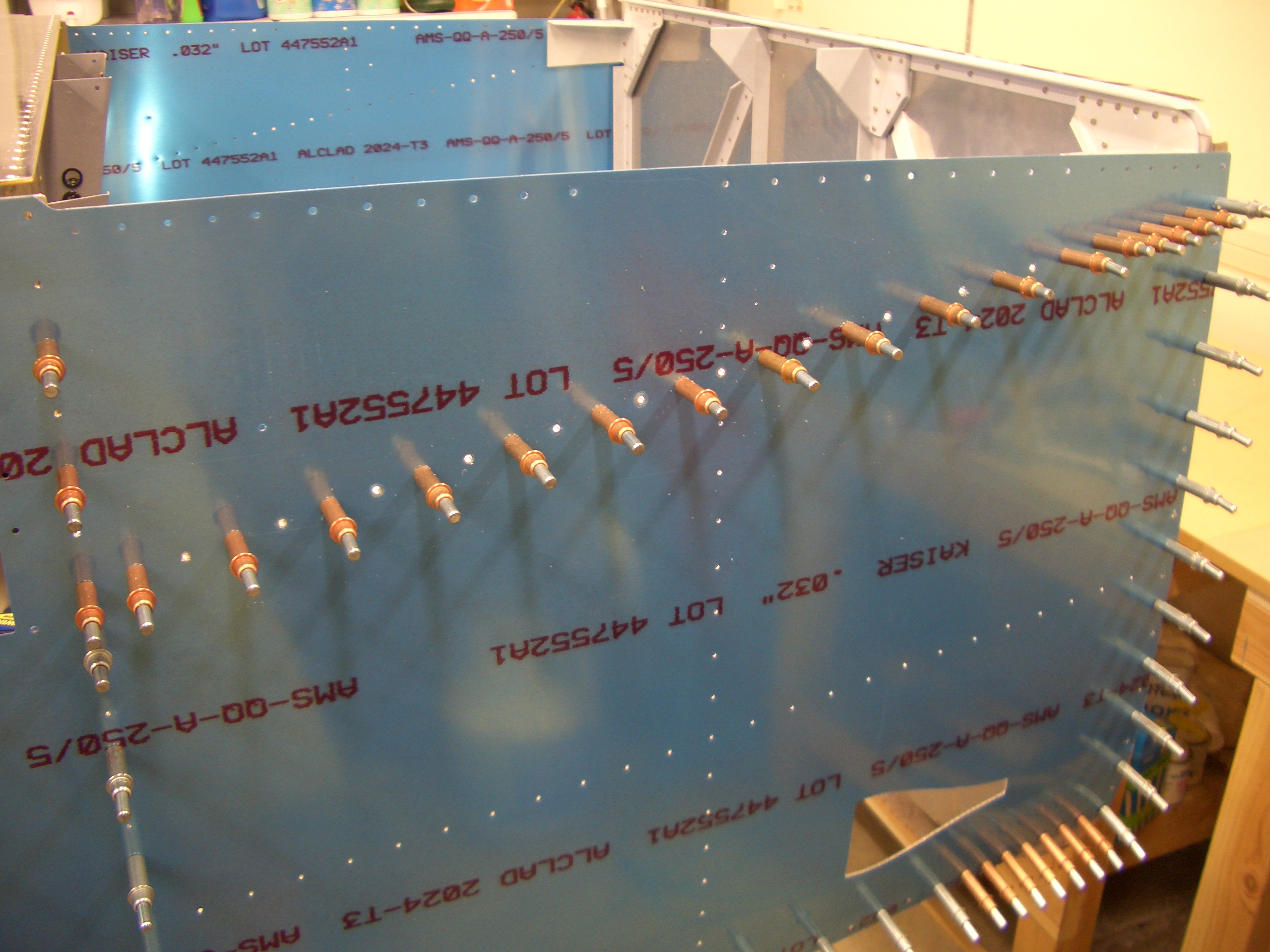
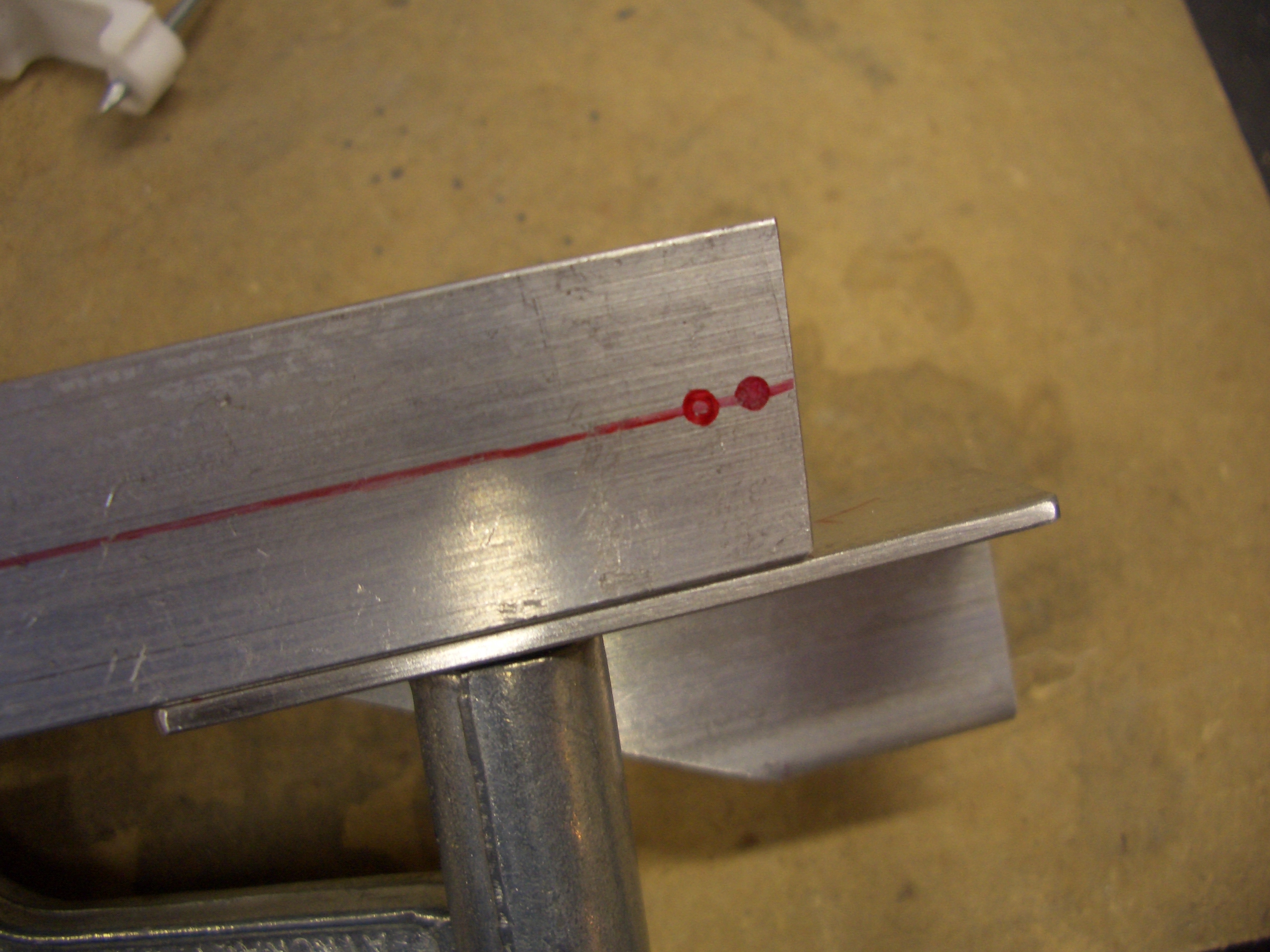
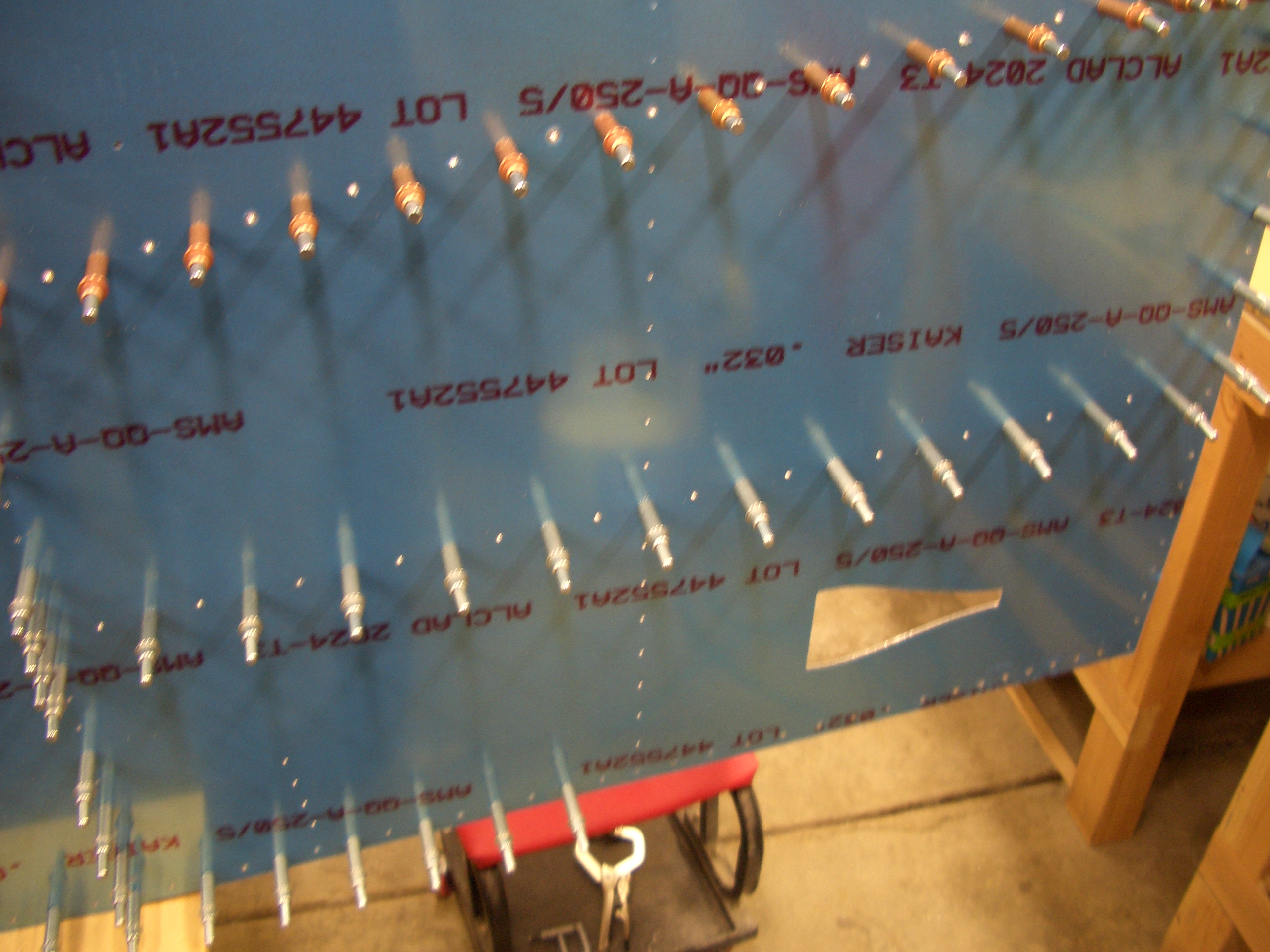
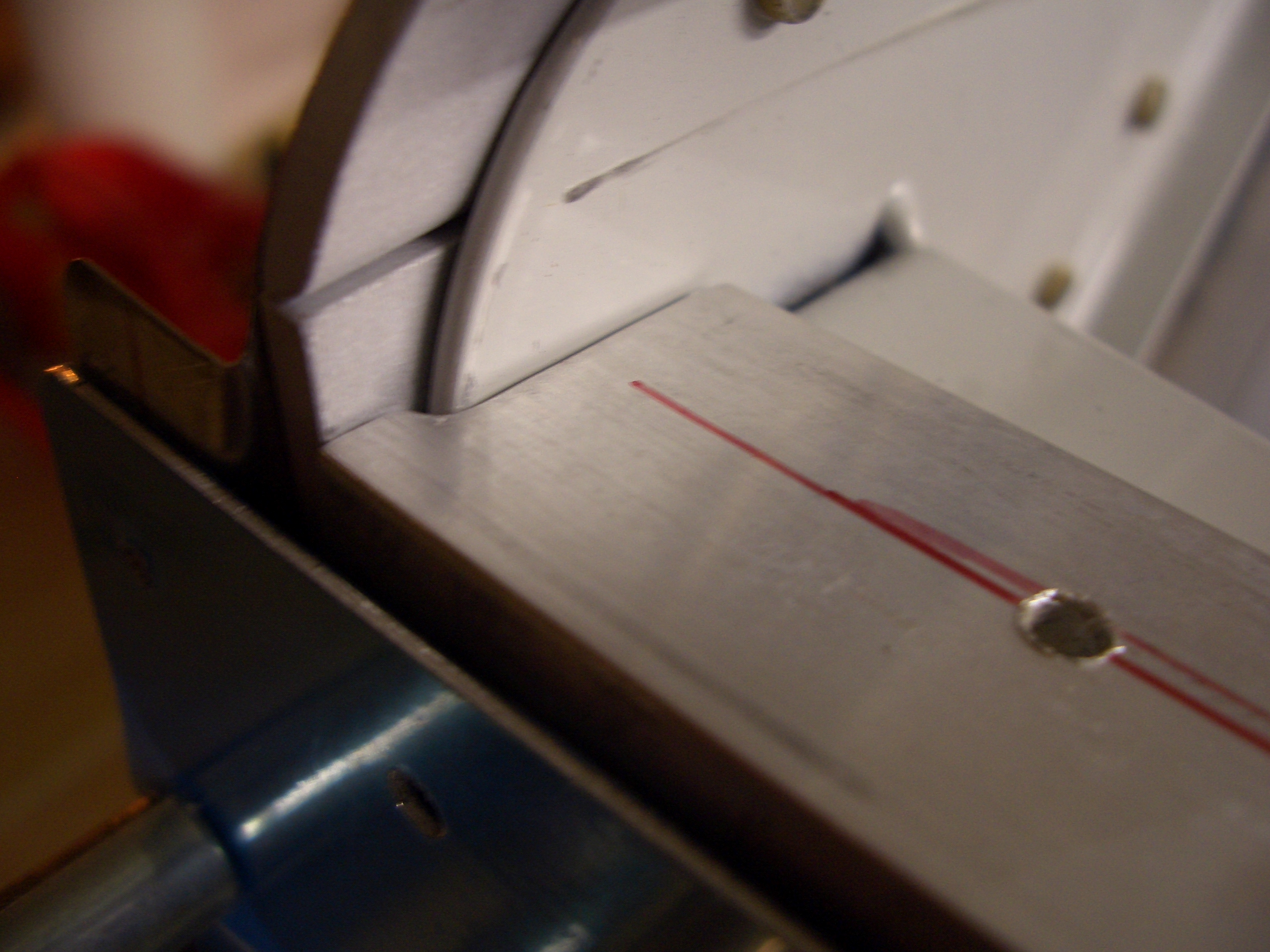
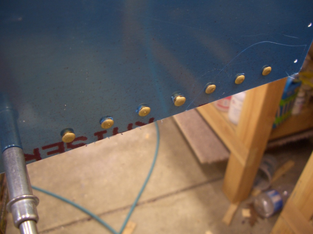
Finally, the forward bottom skin can be clecoed on.  Make sure you draw the centerline on the lower firewall stiffener before doing this.

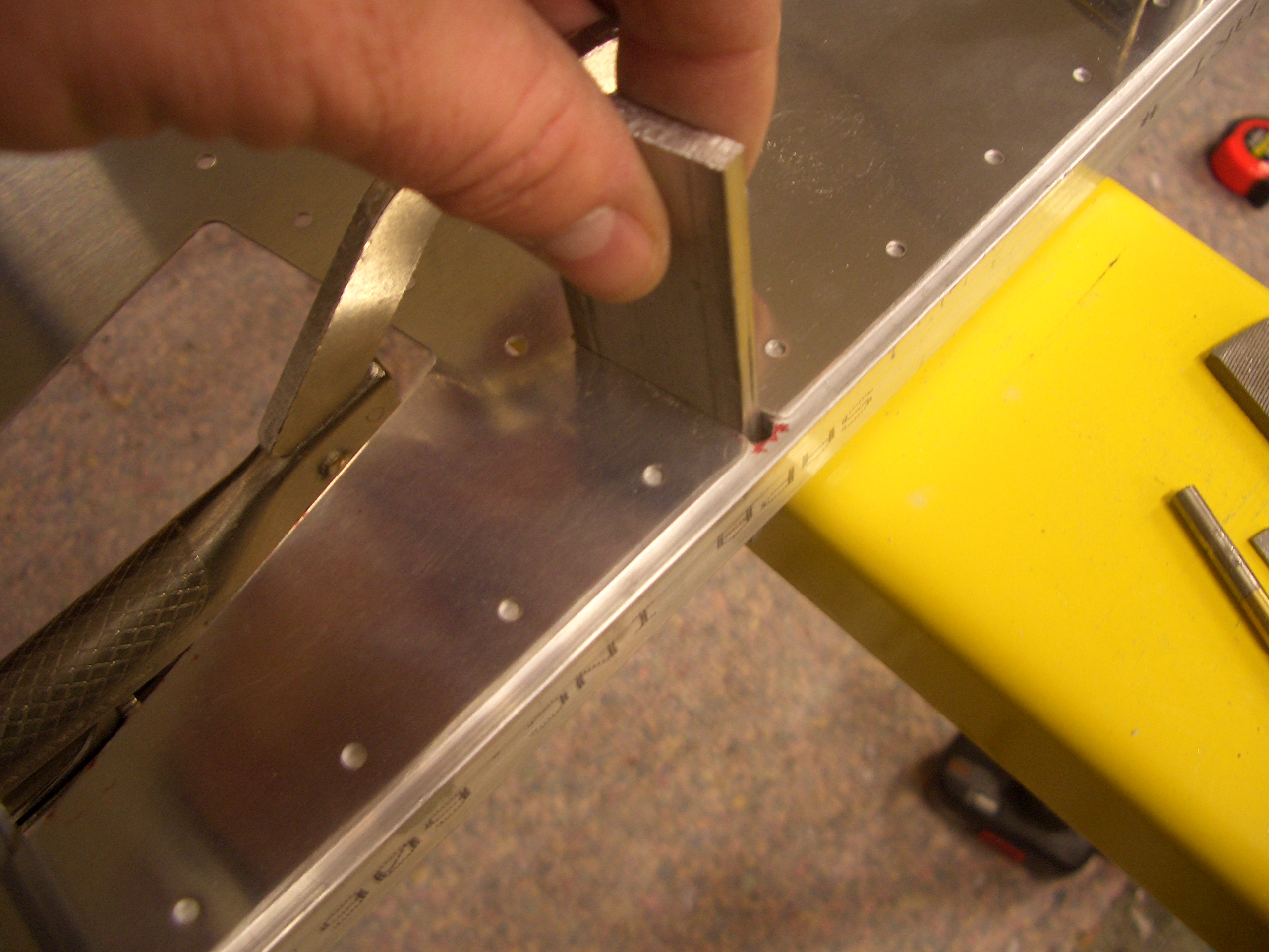
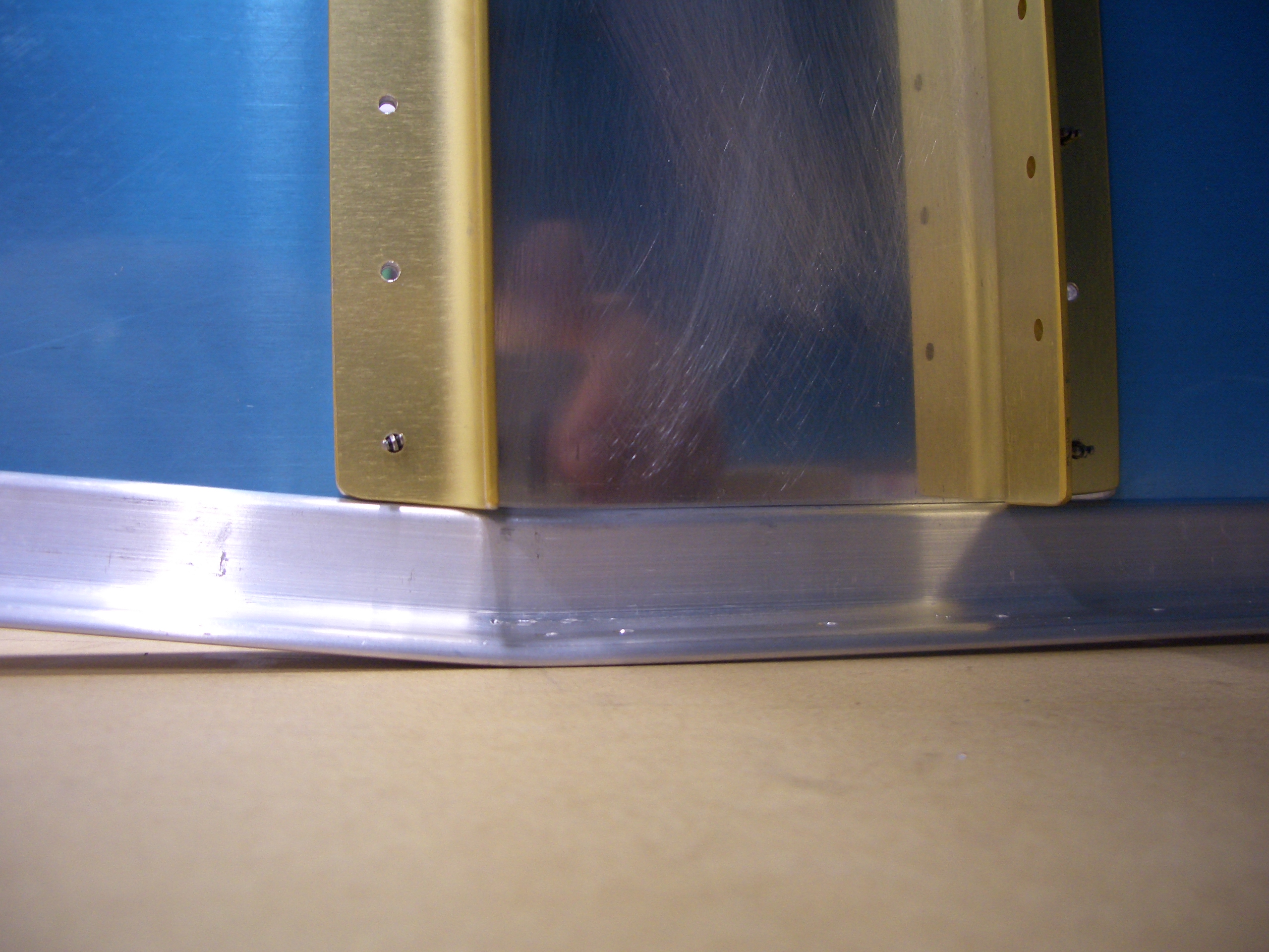
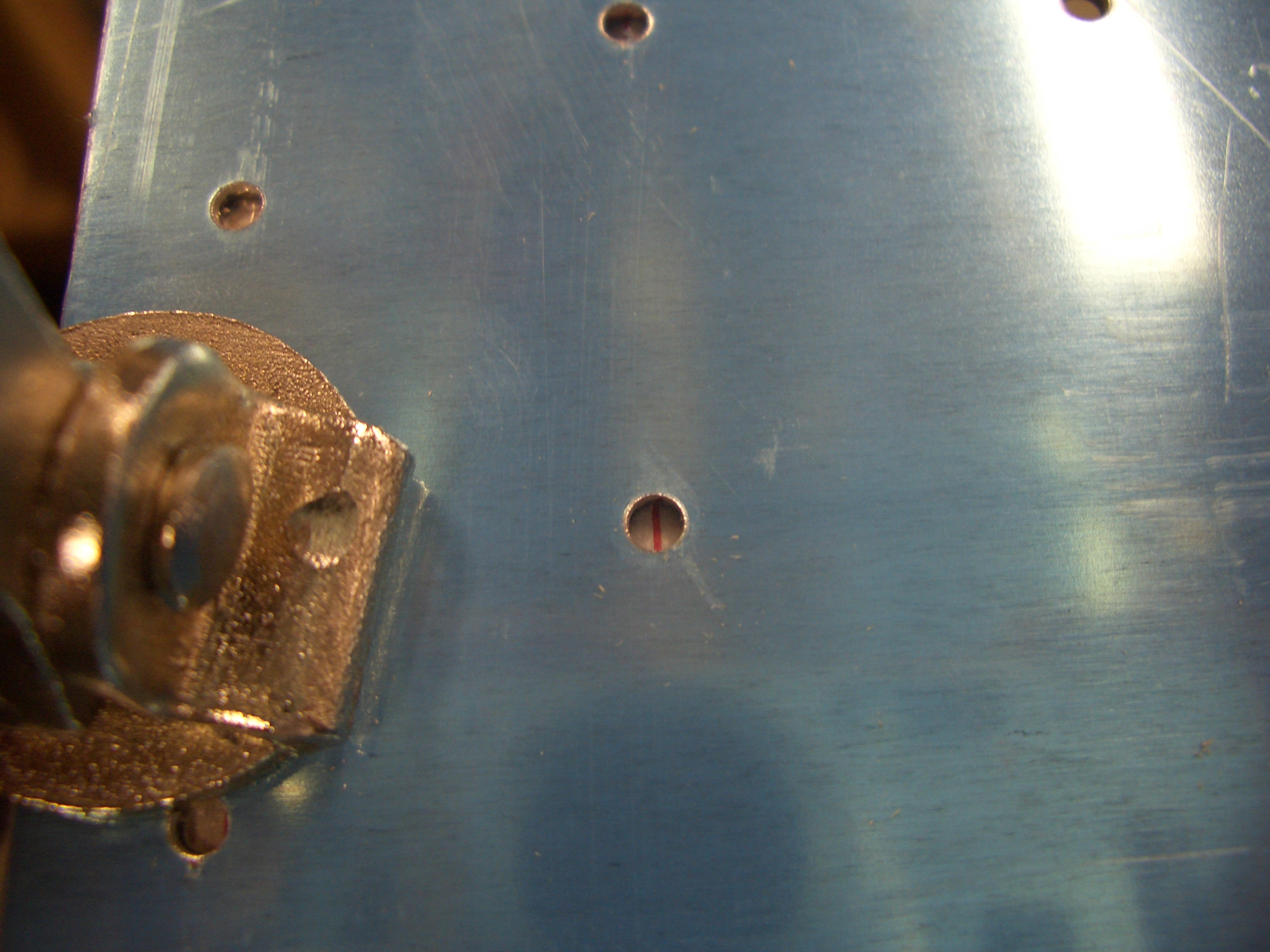
The centerline on this stiffener should land in the second row of holes on the bottom skin.

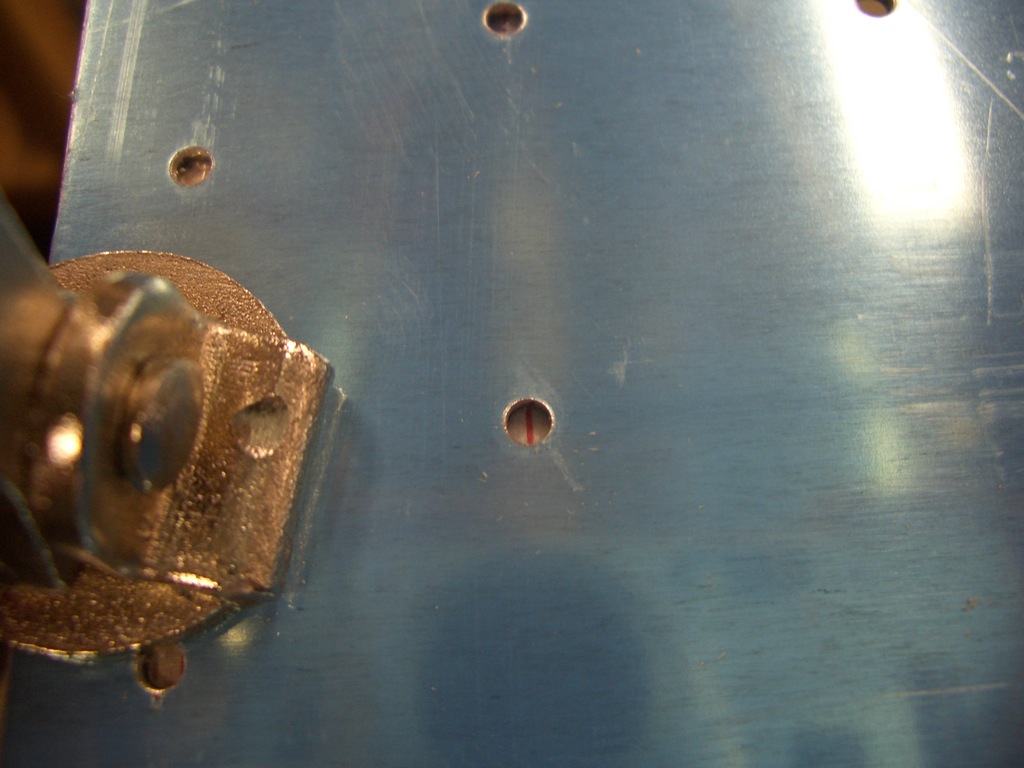
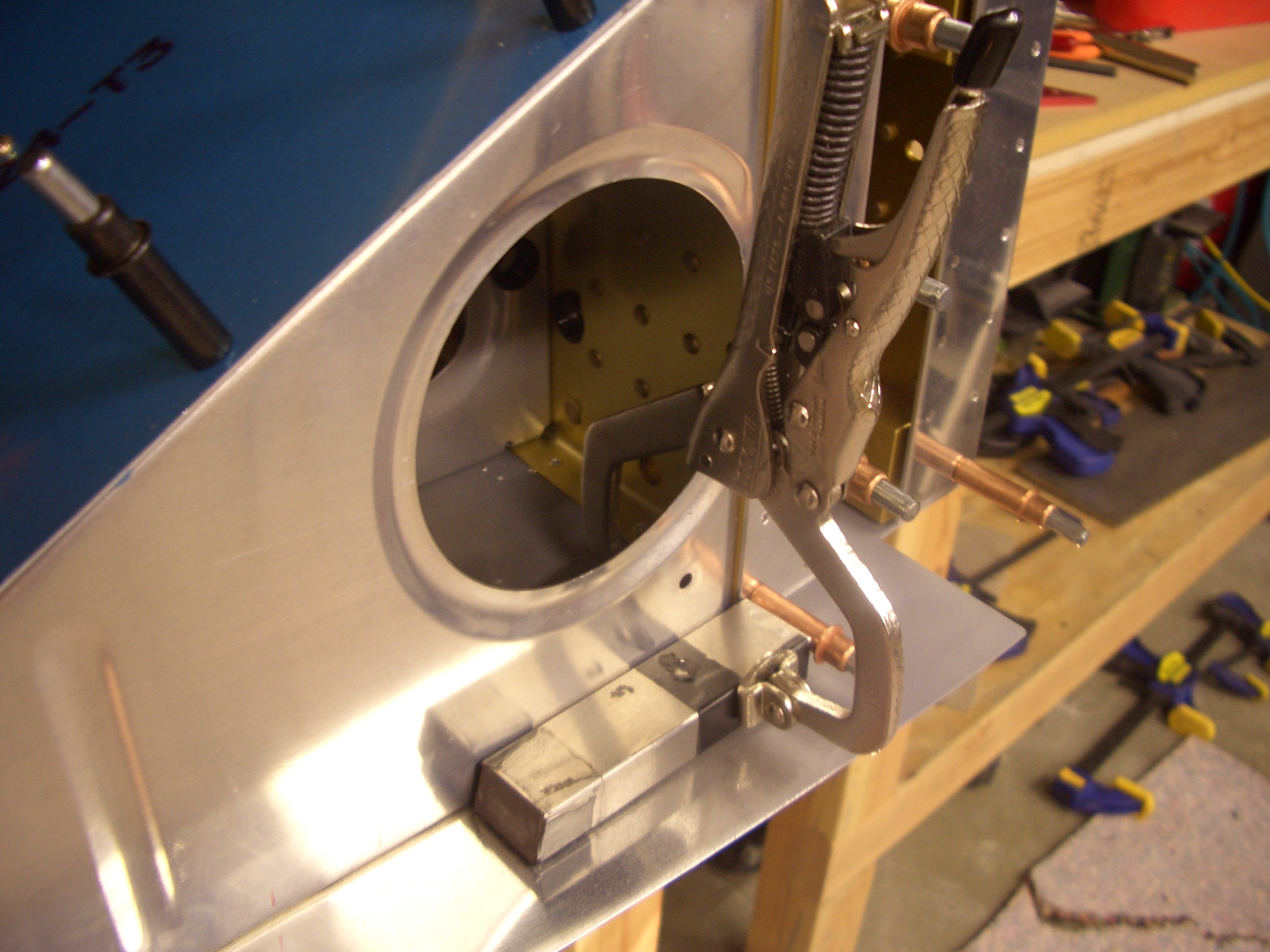
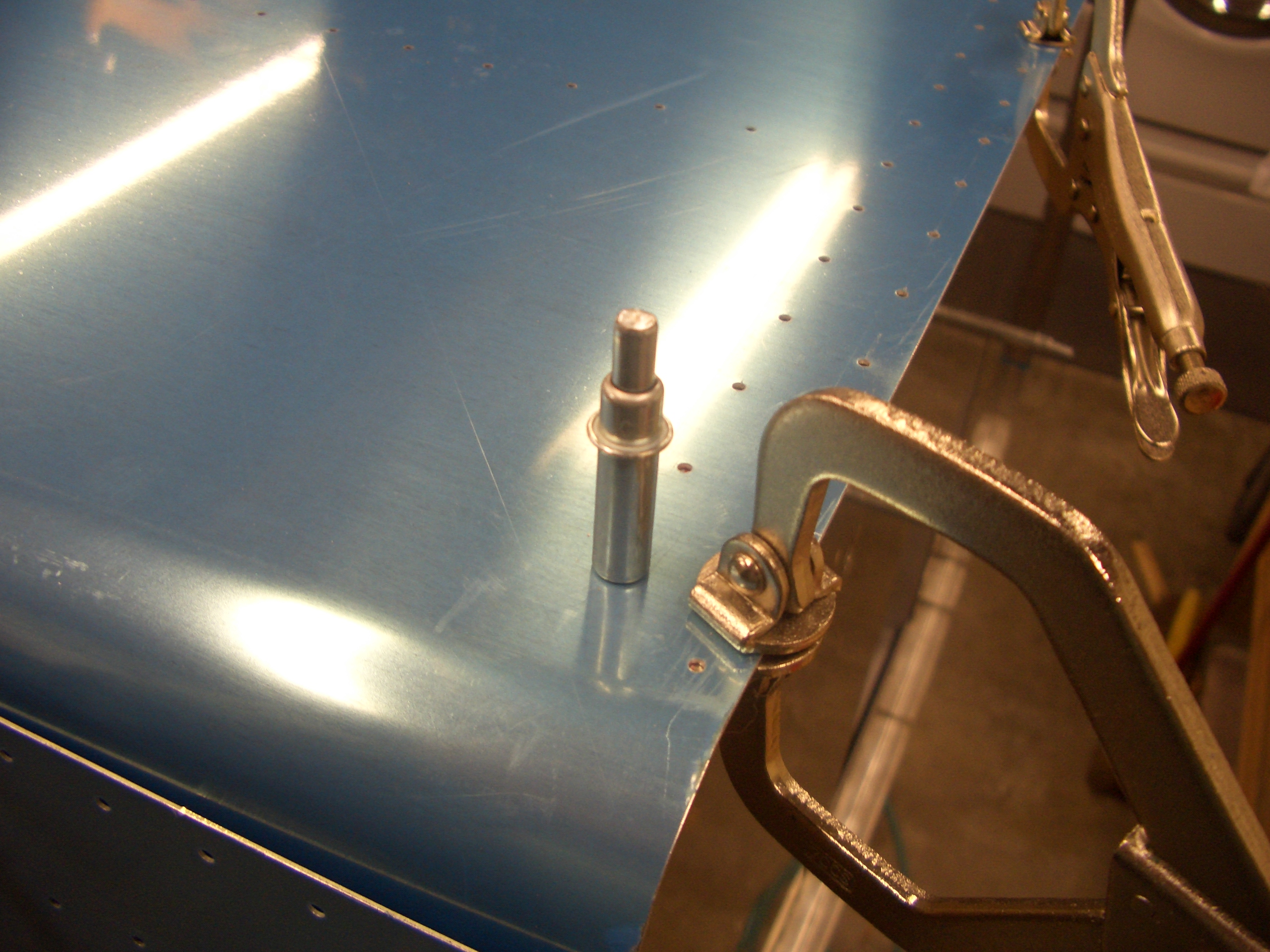
I drilled one hole at each end of the bottom stiffener to lock in the correct position of the firewall.

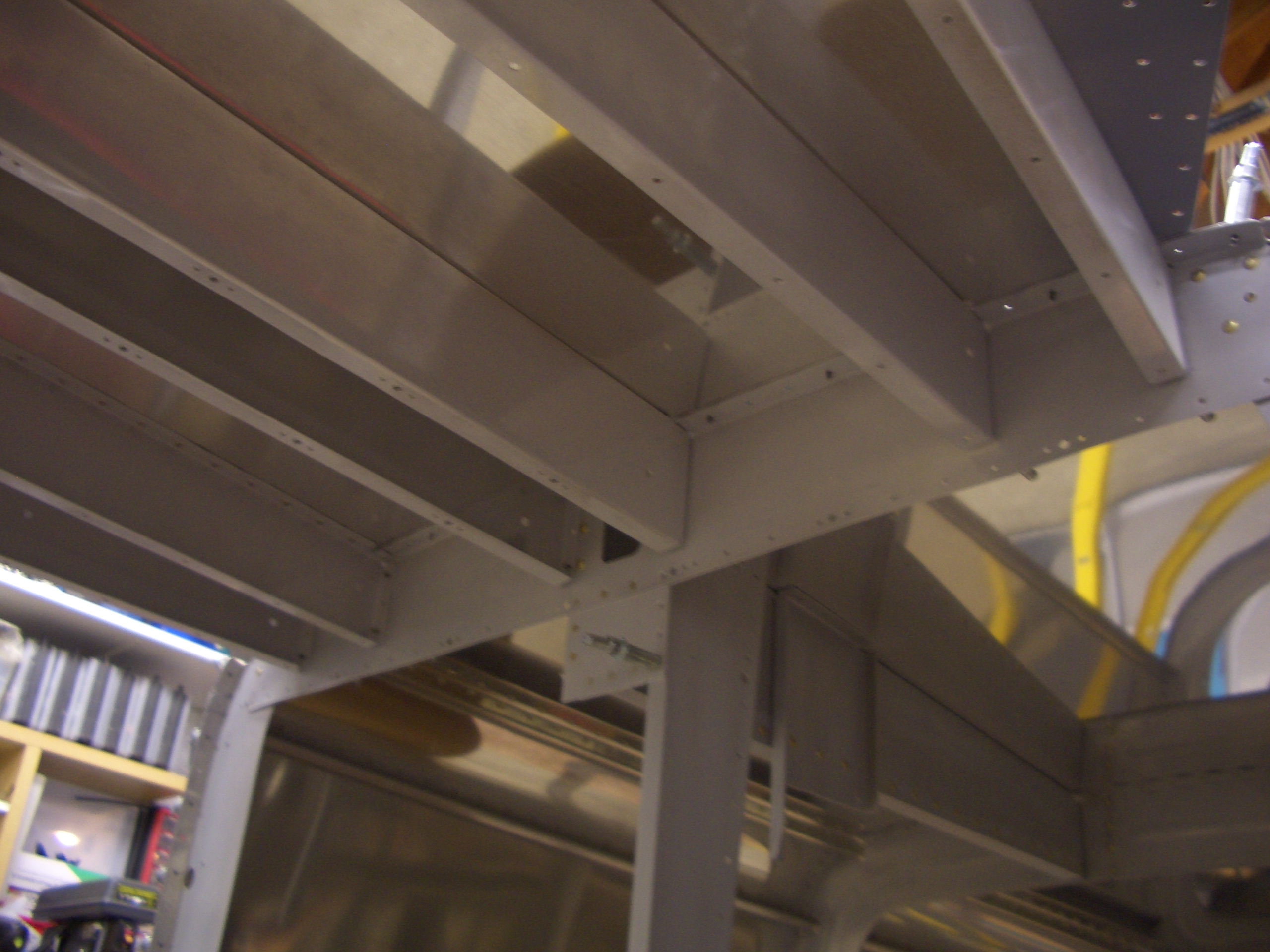
Next, I double checked that the ears on the upper engine mounts were nestled tightly into the corner of the longeron and tightly clamped.

The plans say to take a break at this point, and it’s pretty late, so this is a good stopping point for the night.

Drilled Firewall and Aux Longerons

So far during the build, I’ve almost used 1 qt of primer.  I was just about out, so I ordered another quart.  This should easily get me through the rest of the build.  Because I’m only priming the interior structure and not the wing skins, and even then I’m applying a very thin coat (more of a fogging than a coating), I’m sure this will get me through the rest of the build.  I doubt I’ll add more than a pound or two of primer to the whole plane.

I also picked up 8 brand new Hartwell H-4603 latches off eBay for $5 each.  I’m thinking about using some of these for a couple of storage areas under the baggage floors and I may use a one or two for the oil door in the cowl.  Similar latches are $90/ea at Aircraft Spruce, so this was quite a deal.

I got started tonight by quadruple checking that the firewall was 5/8″ behind the leading edge of the skin and then drilling the firewall to the side skin.  I also drilled the forward seven holes in the upper longeron and into the engine mount (the seven copper colored clecos at the bottom of the picture).

Next, I fit and drilled the F-713 aux longerons.  These require a slight twist since the side skins curve inward near the bottom of the firewall.  I used the same technique I did for the upper longerons (clamp and use a large crescent wrench to twist the hell out of it).

The aft end has to be cut to fit tightly against F-704.

The forward end ties the side skins to the lower engine mount.  There will also be a gusset here which ties all of this into the firewall stiffener that is visible in the lower left of the picture.

Here is the outside of the aux longeron.  This is one of the few areas on the outside of the plane which uses AD4 (1/8″) rivets.  Most of the exterior uses AD3 (3/32″) rivets.

After spending 30 minutes doing the left side, I knocked out the right side in about 10 minutes.

Drilled Left Forward Skin Stiffener

I fabricated the two F-719B angle clips from some raw stock.  I subsequently drilled the two holes on the edge that mates with the skin stiffeners.  I didn’t drill the hole in the other leg since there would then be no easy way to match drill it to the firewall stiffener.

The side stiffeners are rather poorly bent from the factory.  The joggle is necessary so that the stiffener can overlap F-704, but the way they bend these causes the leg of the angle near the joggle to bend outward which prevents it from lying flat on the skin.

To correct this, I laid a piece of scrap 1/8″ angle stock (twice the thickness of the stiffener so it wouldn’t bend) against the side of the skin stiffener and inserted a second piece of scrap at the apex of the bend.

I then used my hand squeezer to slightly overbend the leg of the angle.  It’s easy to overdo it here, so watch out.

Now the leg of the angle is perfectly straight right up to the apex of the bend.

After trimming both ends of the stiffener, I installed it and marked the forward hole to double check edge distance on this rivet (it’s the left hole in this picture).  It turned out 1/32″ over 2d, so that’s perfect.

I match drilled the stiffener to the side skin.

The I removed some of the clecos on the side skin so that I could get a 12″ drill bit in here to match drill the angle clips to the side stiffener.

Finally, I marked the edges of the angle clip and drilled a hole in the center of the area.

Edge distances came out great all around.

Here is the aft end showing how the stiffener steps up onto F-704.  Notice also that the hole to the left is on the flat of the stiffener.  I’ve noticed other builders having problems with the apex of the bend being forward of this hole which creates a gap between the skin and the stiffener at this hole.  If you trim the aft end of the stiffener first to get this hole in the right spot and then trim the forward end to just touch the firewall stiffener, then you can avoid this.

Finished Drilling Skin Stiffeners, Started Lower Longerons

I got started tonight by drilling the right skin stiffener.  Just like most other tasks, the second time went much faster than the first.

Next, I got started fabricating the lower longerons.  These are cut from raw 1″x1.25″x0.125″ angle stock.  The short leg of the angle needs to be removed for the aft 4.125″ of the longeron to provide clearance for a gusset that will tie this to F-704.  I made the rough cuts on a bandsaw and then used various files and scotchbrite roloc disks to get this nice and smooth.

If you look closely, you can see a gap between the horizontal leg of the longeron and the engine mount.  I anticipated that because Mike Bullock ran into the same problem.  The issue is that the lower longer and aux longeron meet at this bracket at an angle and the forward ends interfere.

A few seconds on the sanding wheel removed enough material that the lower longeron can nestle tightly into the bracket.

The longeron also needed to slide forward a bit to allow the rear end to fit next to F-704.  I could have just cut this off flush, but this relief cut gives me more edge distance on the frontmost bolt on the top and rivet on the side.

Here you can see how the aft end sits flush against the forward edge of F-704.

Before drilling any holes, I wanted to see what kind of edge distance I would have on the AN3 bolts that tie the longerons to the engine bracket.  The bolts are supposed to be centered in the longeron (1/2″ from the left edge where my finger is).  This gives me about 5/16″ edge distance for the bolt.  I know other builders have run into issues with edge distance here, so I want to make sure this is sufficient.

Update: I spoke with Ken at Van’s the next morning and he confirmed that 10/32″ was fine.

Finished Lower Longerons

I fit the lower right longeron.  Here is the forward end showing how it tucks around the lower engine mount.  I also drilled the bottom holes out to #30 to see what kind of edge distance I’d end up with on the mount.  You can sort of tell here that I biased the holes 1/16″ inboard of the center point on the longerons to give me slightly more edge distance on the steel.

Here you can see that I ended up with just over 12/32″ on the engine mount.  This is perfect as it means I more than 2d on both the mount and the longerons.

I first match drilled the mount to #30.

I then opened up each hole with a #15 bit (0.180″) before reaming it with a 3/16″ (0.1875) reamer.  I’m trying to only use reamers for all of the bolt holes.  They make perfectly circular holes that allow the bolts to slip in with virtually no play.  Here I’ve dropped some AN3 bolts in place to keep things aligned.  btw, it’s not an optical illusion, the bolts are intentionally spaced unevenly on the plans.

I repeated the procedure on the left side.  Edge distances came out great here as well with over 2d on all holes.

I laid out the F-684 gussets on the stock provided.  The area at the top and lower left that are marked with hatches need to be removed.

Two sides of the gusset need to be bent a few degrees to allow it to set flush on the engine mount and firewall stiffener.

After very careful checking to ensure sufficient edge distance, I drilled the left gusset to the lower engine mount.  I ended up with better than 2d on all holes but the one on the right which ended up at exactly 2d.

The skin can then be peeled back and the firewall stiffener can be match drilled using the holes I predrilled in the gusset.

All of these holes came out great as well with 2d or better all the way around,

I then repeated the process on the right side.  This came out nearly as well.  The upper left hole came out at slightly under 2d, but that’s still within spec.  This finishes up the forward longerons and skin stiffeners.