Primed Canopy and Fixed Pitot and AOA Tubing

I sanded down the epoxy I applied the other night and painted on a few coats of primer.  There are a few pinholes I need to deal with, but this is good enough for first flight.

Between coats of primer, I fixed the pitot and angle of attack tubing.  I had previously made these connections in the wing root, but that was a mistake since there’s no room to ever service them.  I had planned on running new lines down the conduit, but I realized I could use the same lines if I added a couple of additional connectors in the wing.  I disconnected the tubing at the pitot tube and slid it inboard inside the wing enough that I could pull the excess through the holes in the fuselage.  These fittings will now be trivial to service if that is ever necessary.

I then cut the lines in the wing and took some longer pieces and ran them from the pitot tube to these fittings.  This is better anyway since I can disconnect the tubing here and pull the pitot tube out of the mount.  This is looking up into the inspection port just inboard of the pitot mast.  With the way the lines were previously run, pulling the pitot tube out of the mount required disconnecting the lines right at the top of the mount.  That wasn’t too painful, but reinstalling the pitot tube was a real pain since it required hooking up the tubing entirely by feel.  This way, the fittings are easy to inspect and verify correct installation.

Weight and Balance

My big goal for the day was to compute the weight and balance.  To do that, I needed to have the plane ready for flight.

In preparation for reinstalling the canopy (hopefully for the last time), I applied a strip of UHMW tape under the leading edge.  This will help the flange slide over the weatherstripping without catching and dragging on it.

I then used a razor blade to trim the tape flush width the edges of the skin.

I then installed the wing root fairing.  I didn’t bother tightening all of the screws all of the way since that wouldn’t change the weight or CG.

The plans say to trim the rubber seal to just touch the fuselage, but I think it looks better to leave the whole seal and have it flare out at the fuselage.  It probably seals against the fuselage better too.

I also installed the wingtips with the landing lights and mounting plates.

I reinstalled the spinner and the cowl.

Jenn stopped by the hangar and helped me install the canopy.

I then installed all of the interior.

After installing the empennage fairings and all of the wing inspection panels, I leveled the plane and put it on scales.  I came in right at 1100 lbs which is great.  It probably means I’ll be around 1130 or so with gear fairings and paint.  My center of gravity is farther aft than I would have liked at 81.35″, or 2.65″ aft of the forward limit.  This makes it fairly easy to load aft of the aft CG limit, so I’m likely going to have to shift some weight forward or add more weight under the cowl.

Continued Reassembly

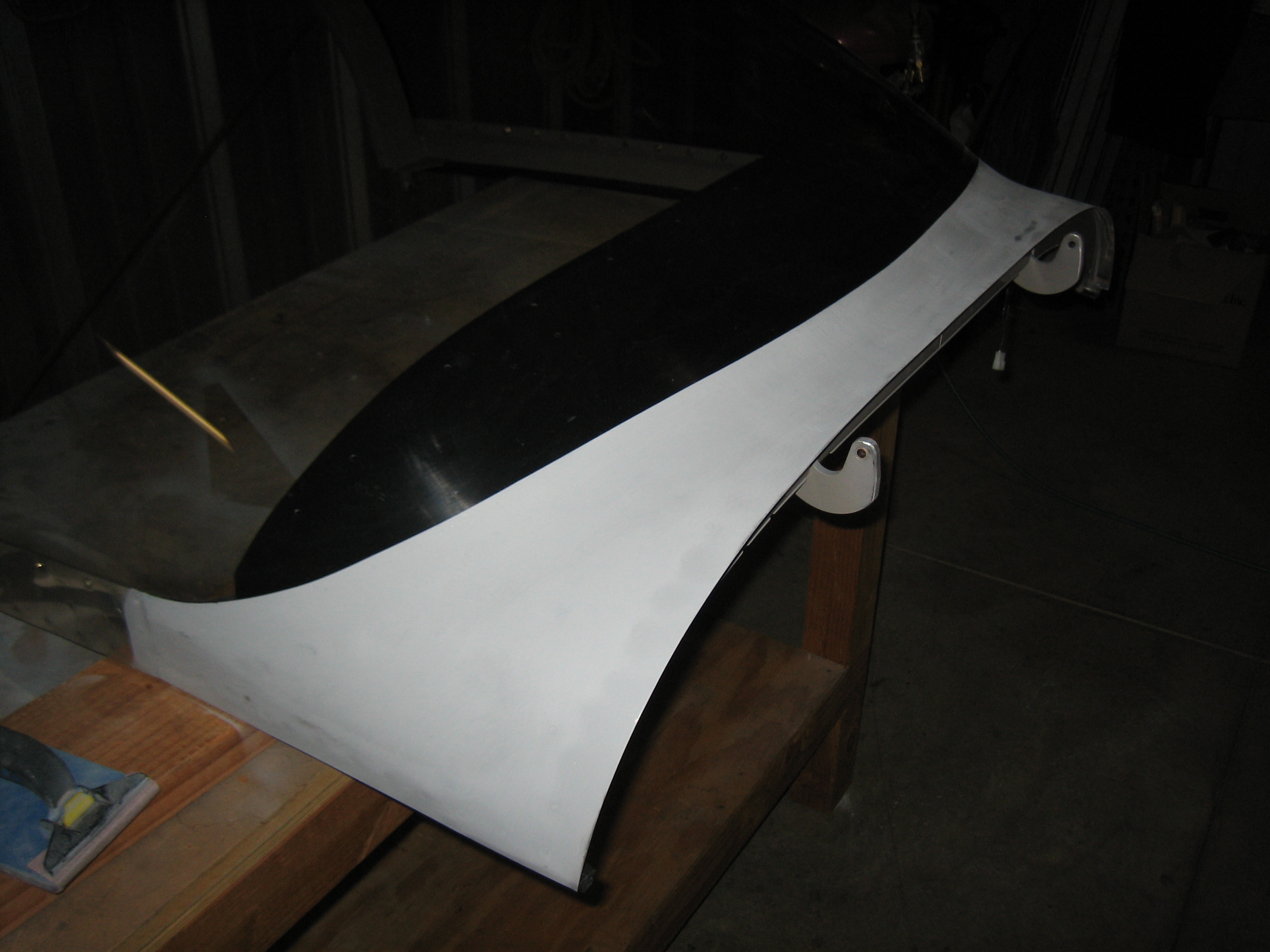
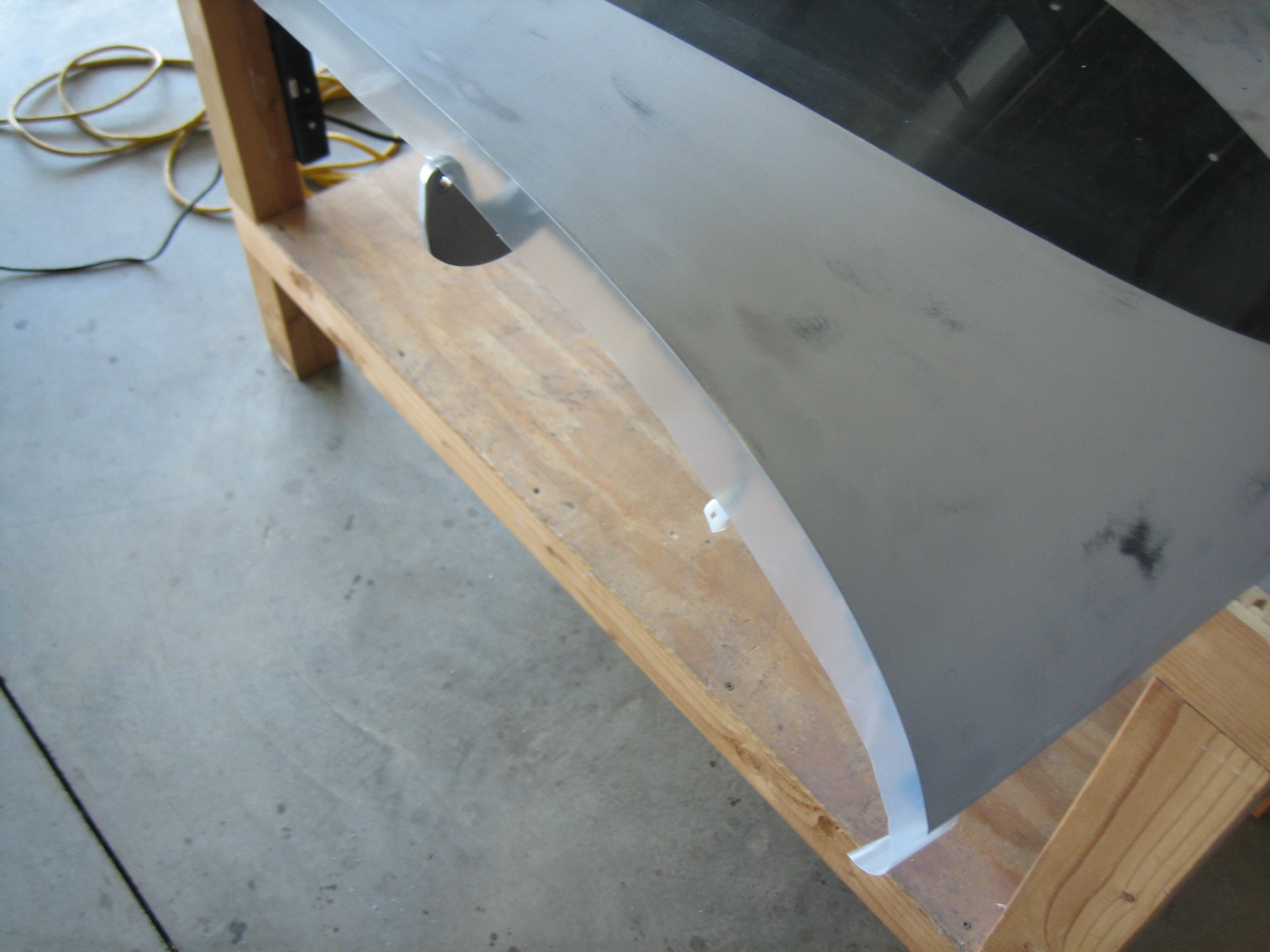
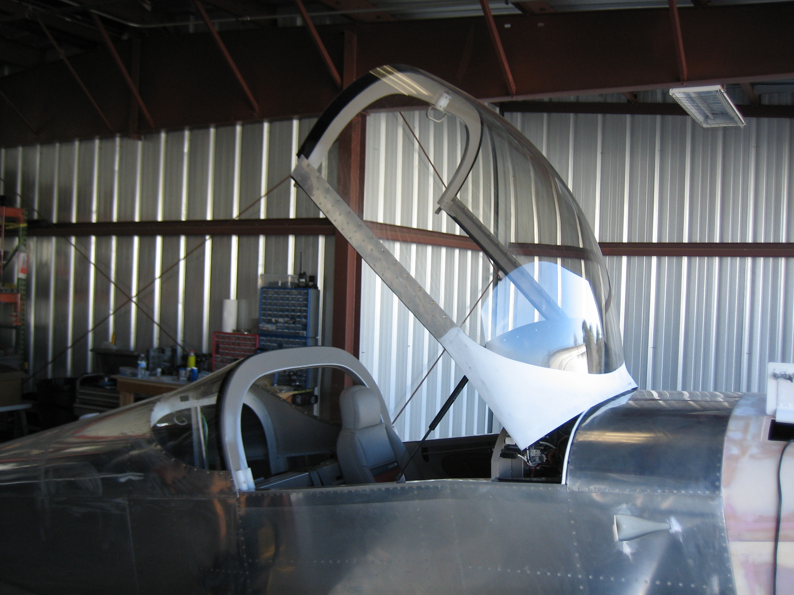
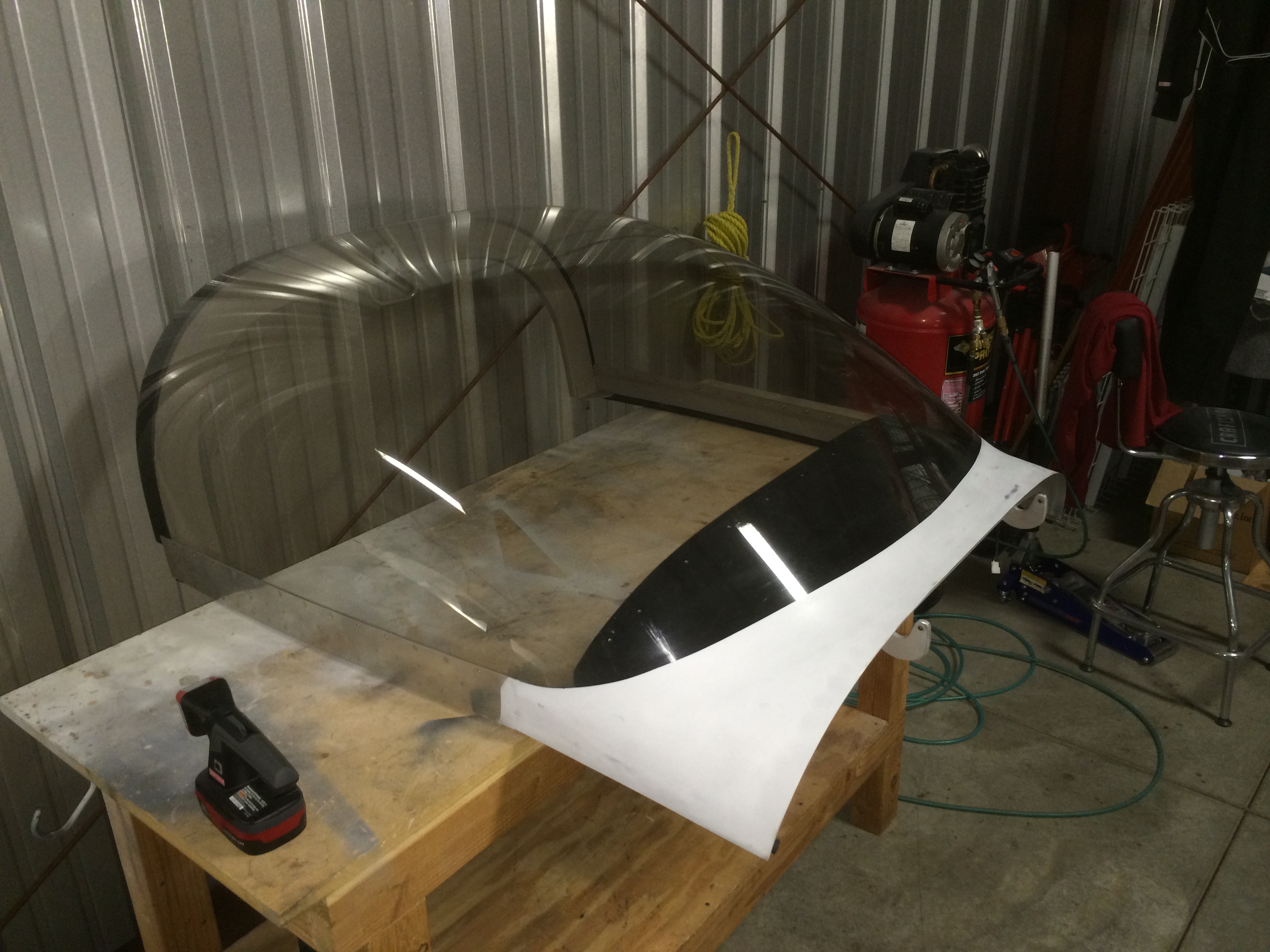
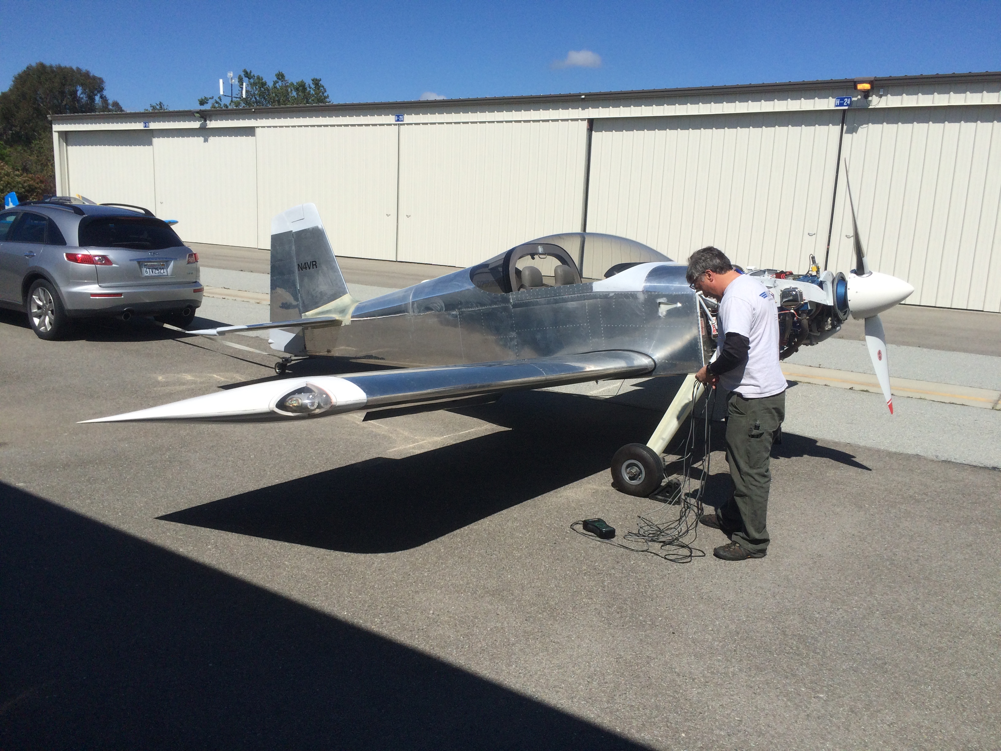
My buddy Andre stopped by the hangar this morning to help me remove the canopy one last time.

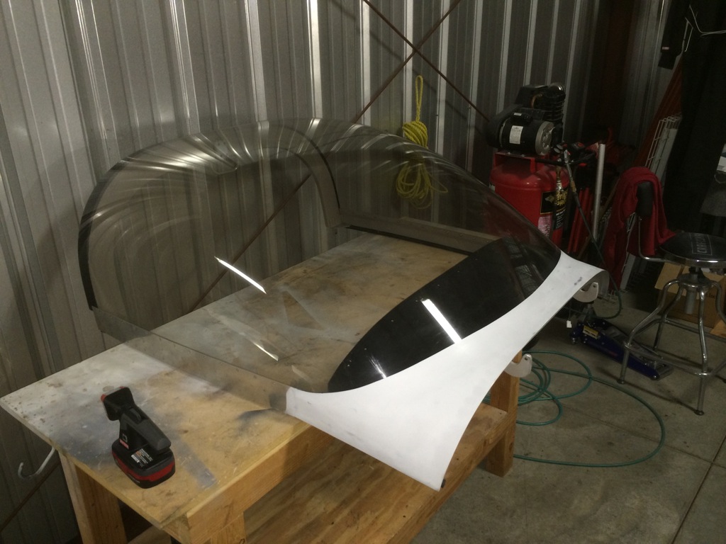
I inadvertently used the wrong weatherstripping on the flange at the forward edge.  It was too thick, and the canopy skin kept catching on it and was tearing it off.  After Jenn and I reinstalled the canopy the last time, I found the correct weatherstripping in a box, so I decided to swap it before first flight.  Unfortunately, after Andre and I removed the canopy, I could no longer find it, so I have some new weatherstripping on order.

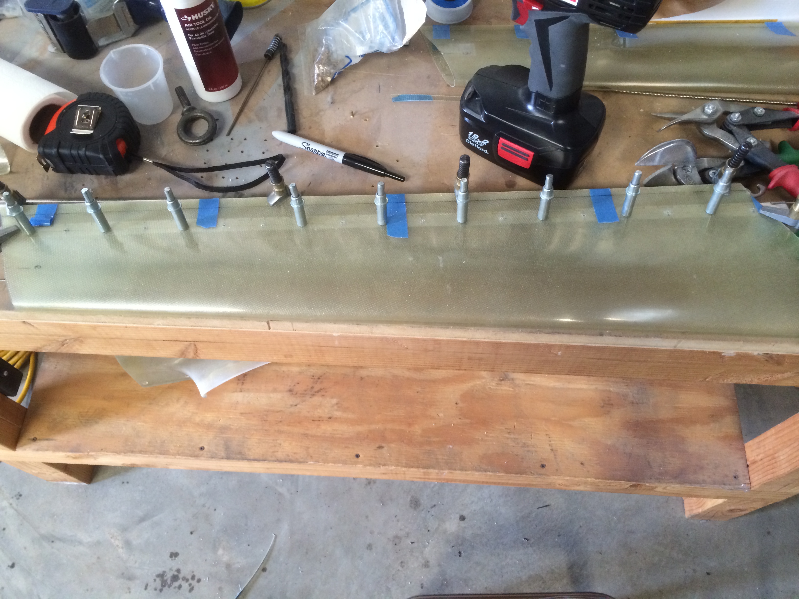
I didn’t get any pictures of it, but I lubricated all of the bearings on the plane.  There are nearly three dozen of them, and many are exposed to the elements.  I’m using a product called DriSlide.  It wicks into the bearing and dries, leaving behind a film of molybdenum disulfide.  This film is extremely slippery, but because it’s dry, it doesn’t attract dust or dirt, is highly resistant to water, and prevents rust and corrosion.  I’m also using it on the sliding pins in the brake calipers to keep dirt from sticking to them.

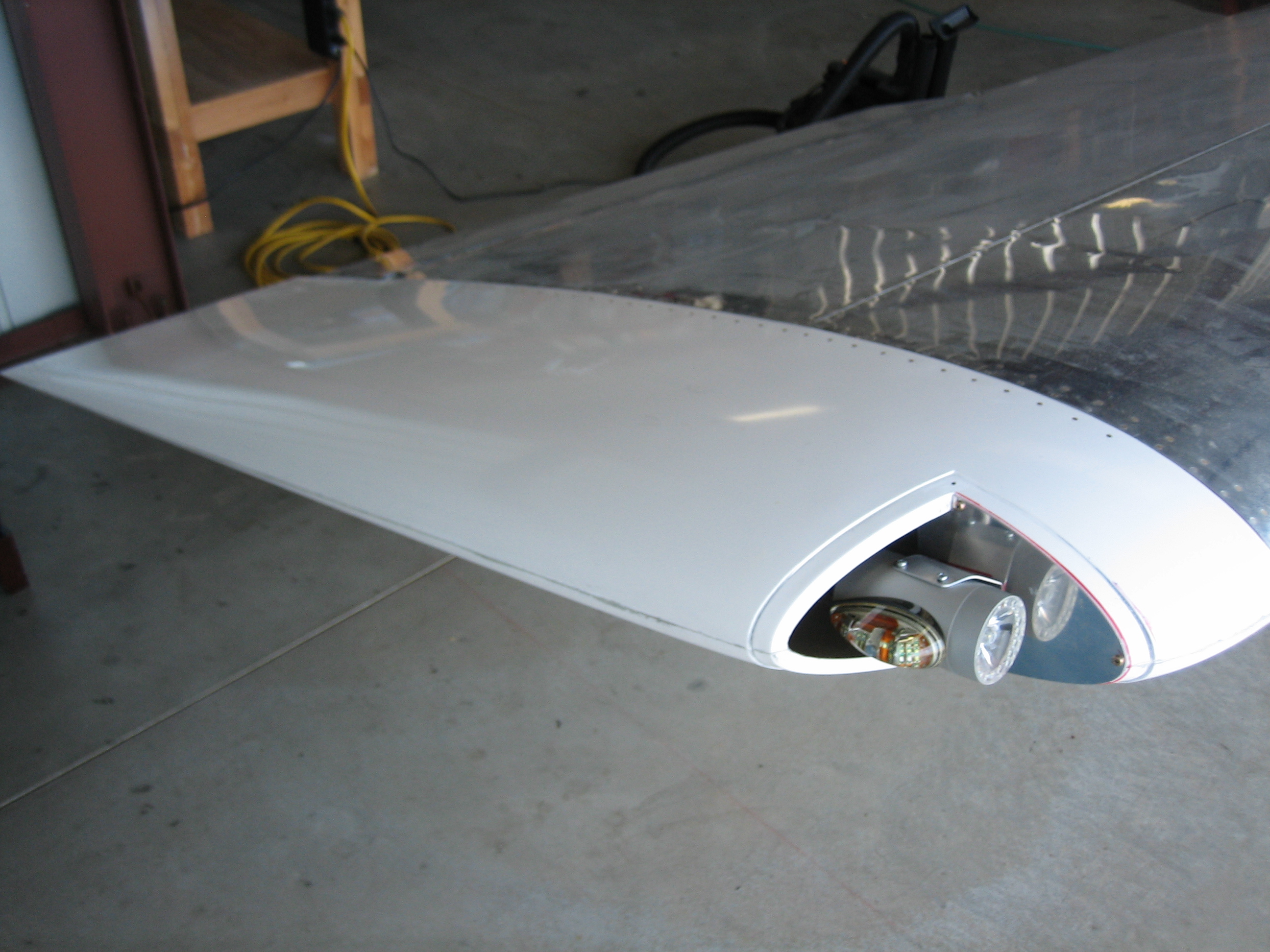
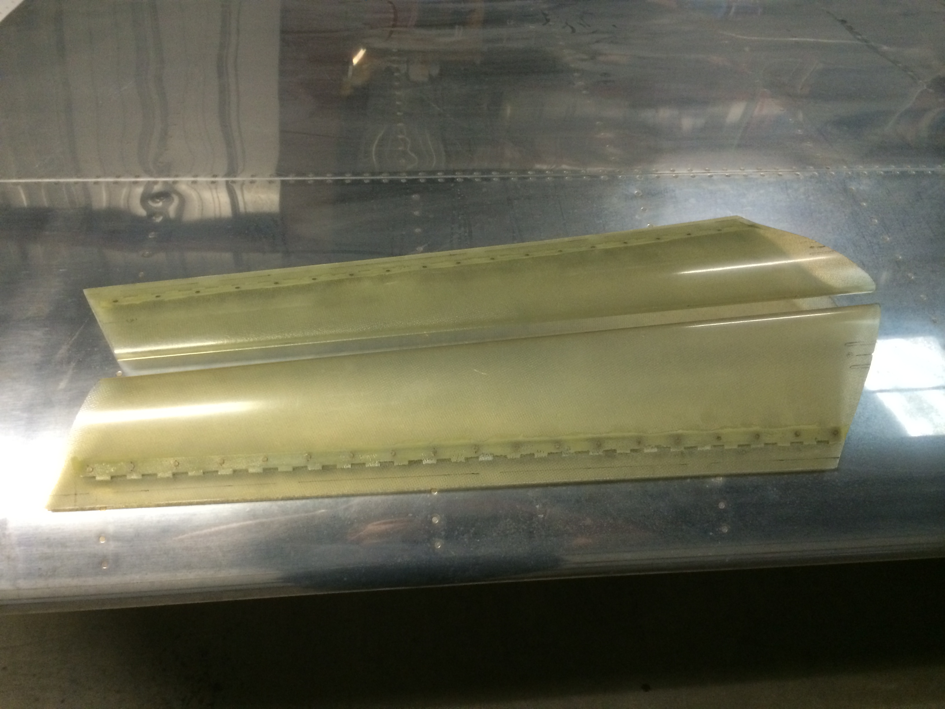
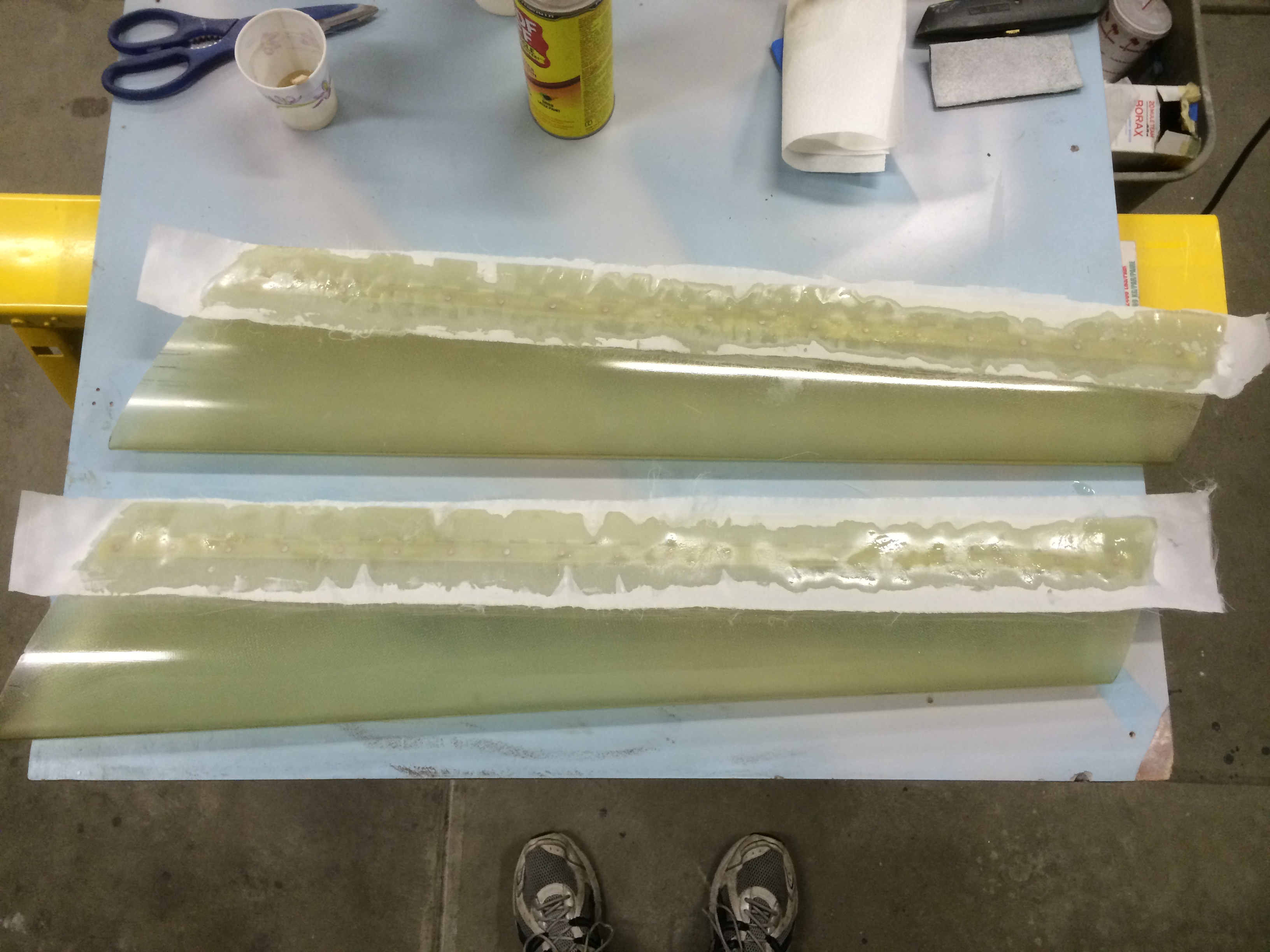
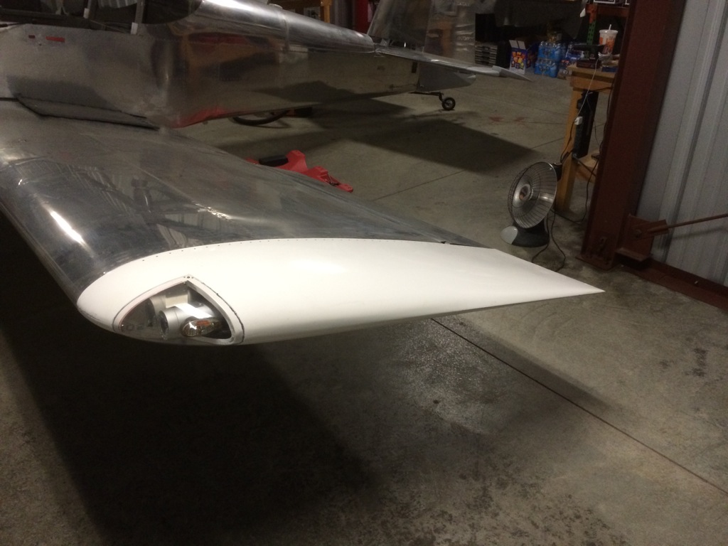
After wrapping that up, I installed the wingtips.  I used some DriSlide on the hinge pins and they slipped in effortlessly.

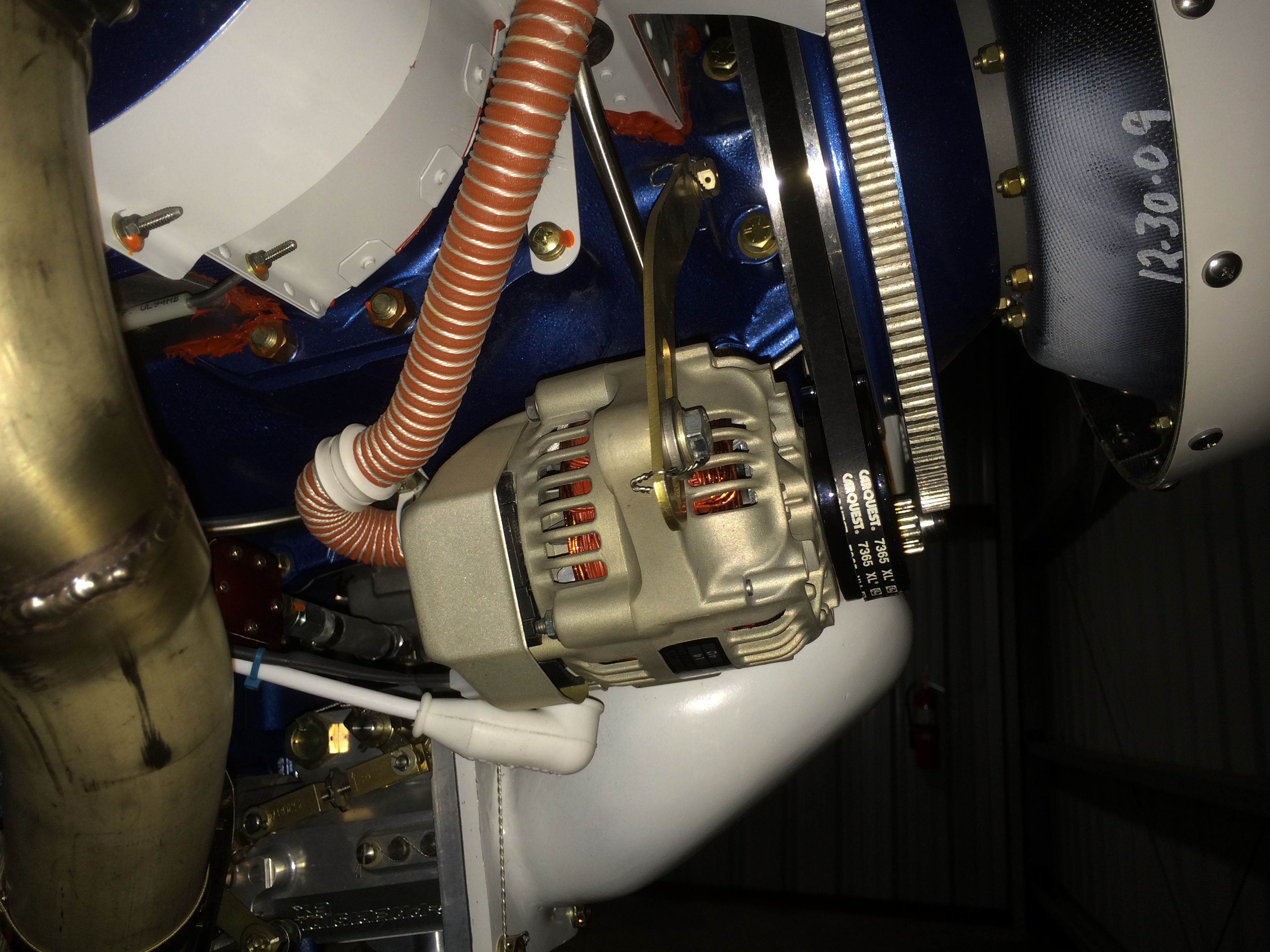
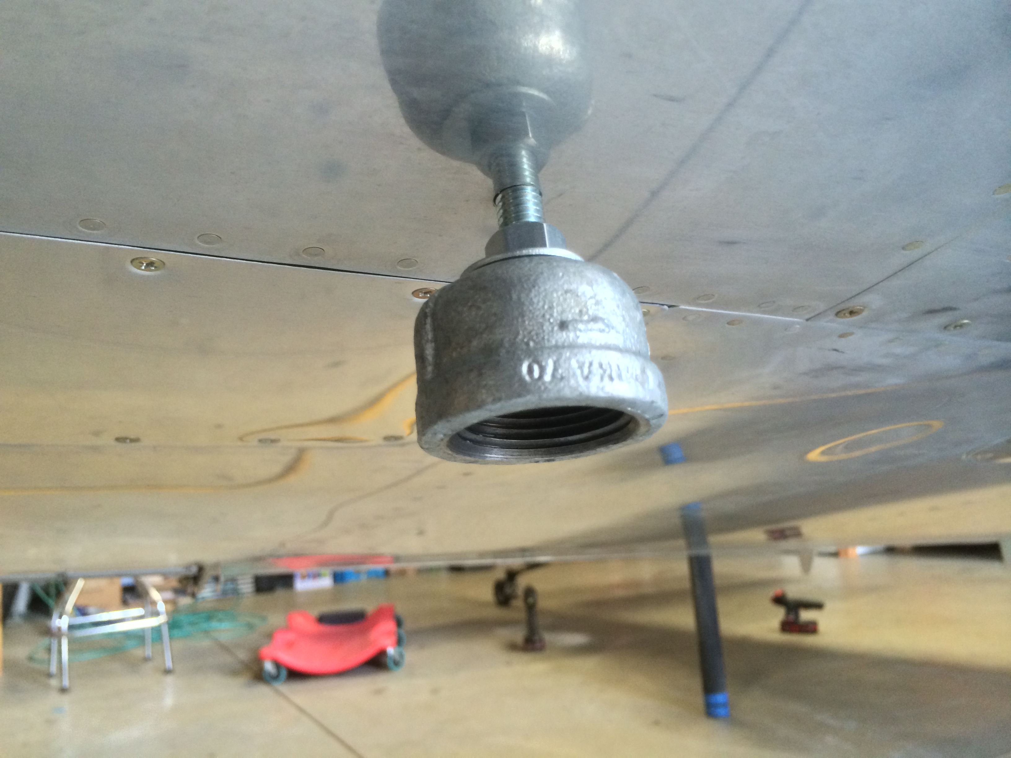
I reinstalled the alternator with the washers in front of the pivot shaft.  I checked the alignment, and it looks perfect.  I adjusted the tension so that I could turn the alternator pulley with 13 ft-lbs of torque (with the pulley slipping on the belt), but couldn’t turn the pulley with 11 ft-lbs of torque.

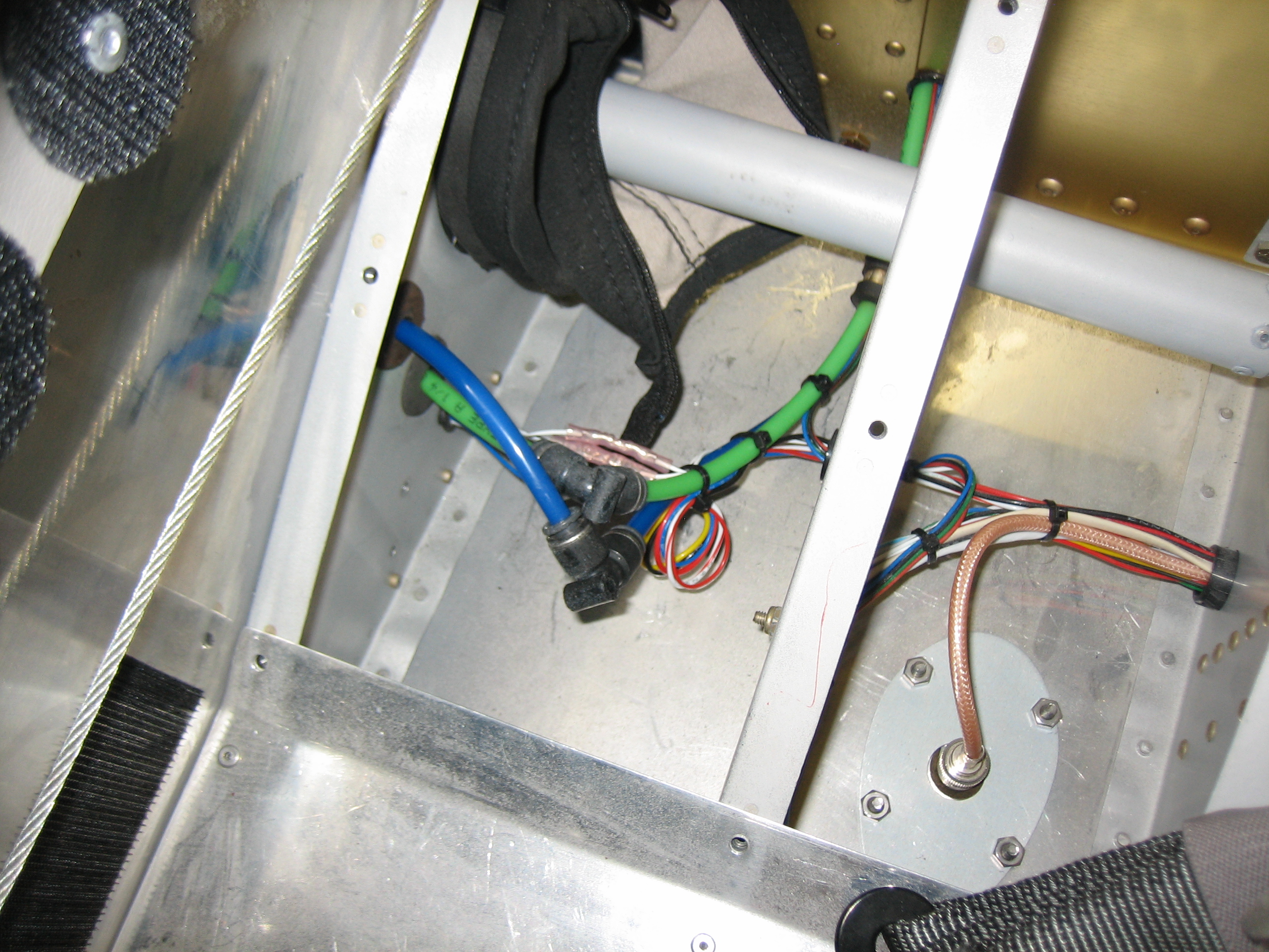
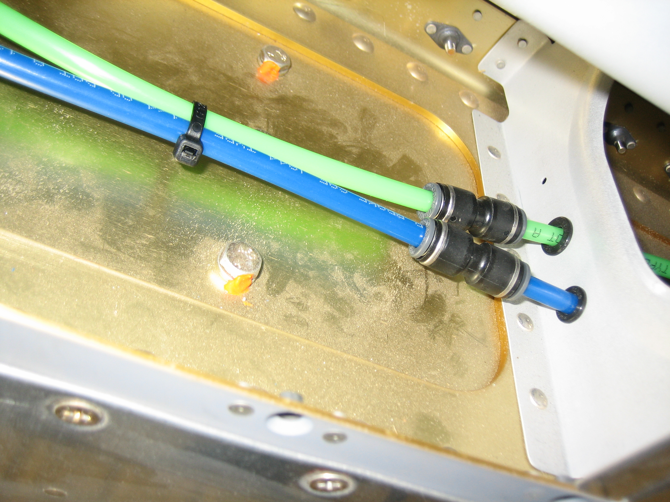
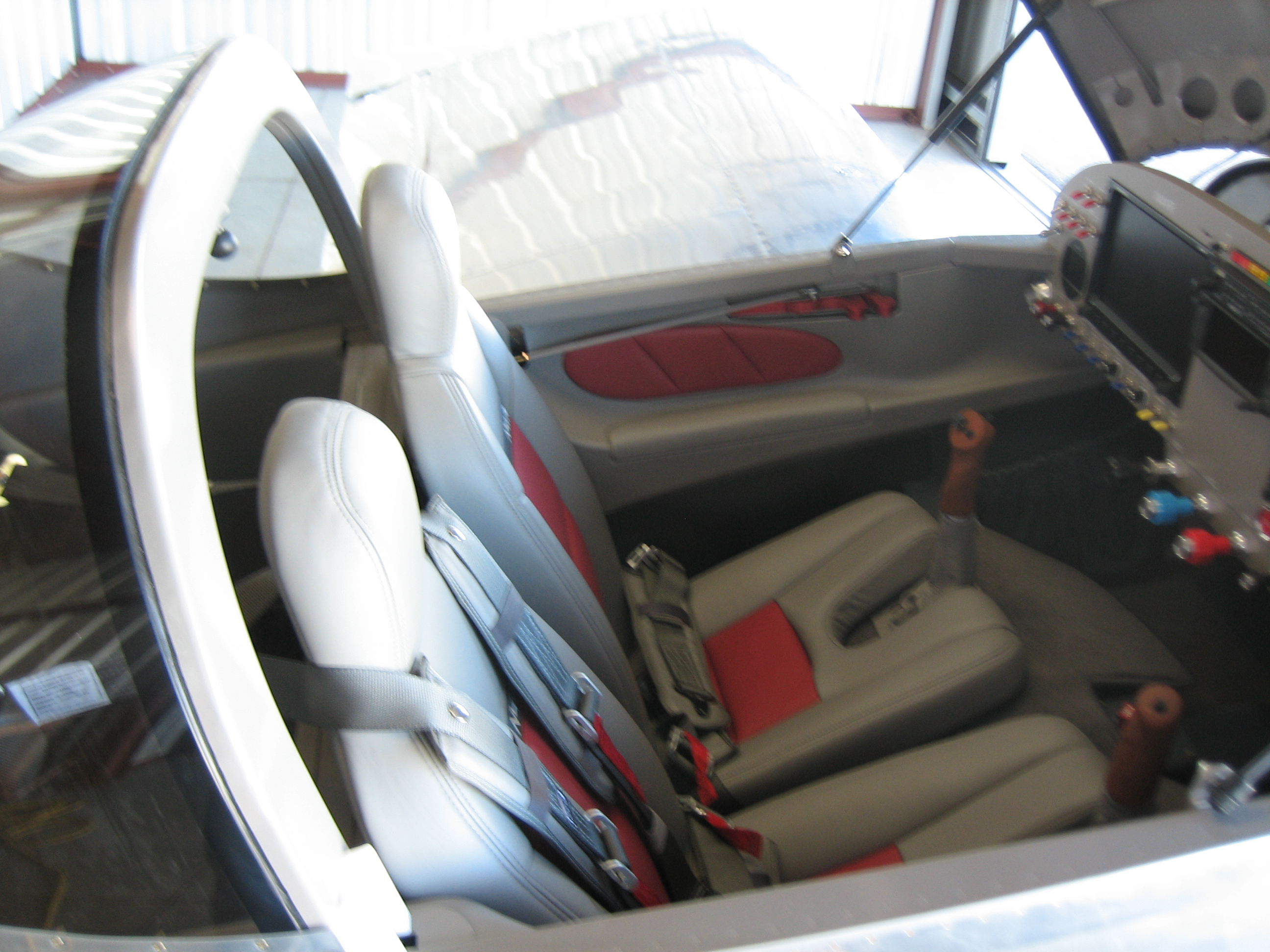
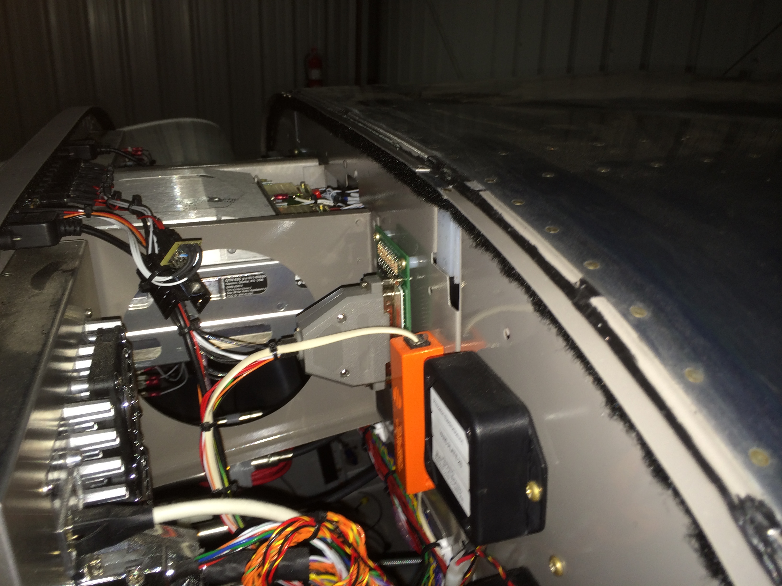
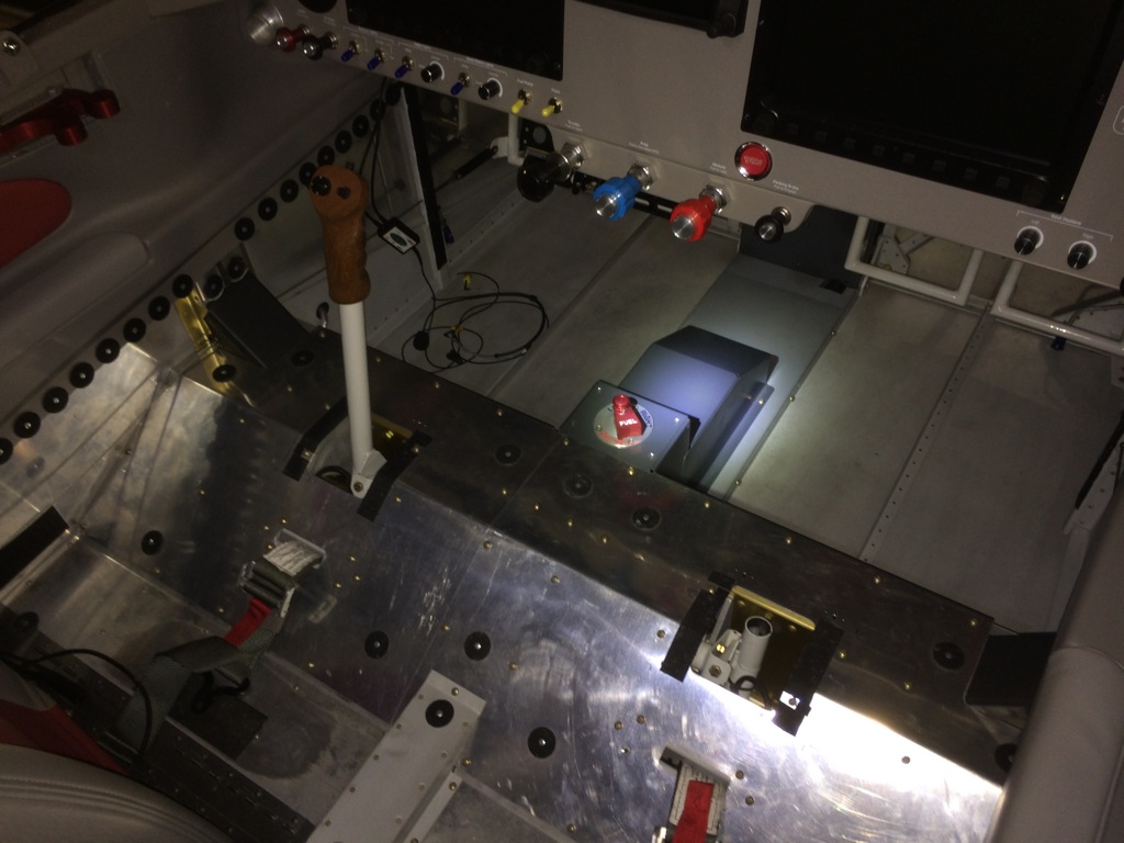
After fully inspecting all of the controls under the seats, I installed the forward center section cover, fuel pump cover, spar covers, seat pans and tunnel cover and screwed everything down.

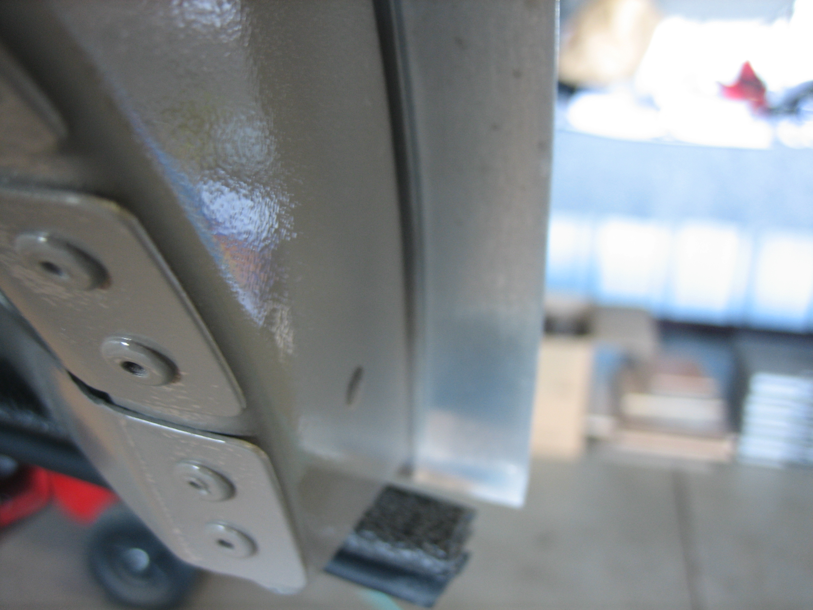
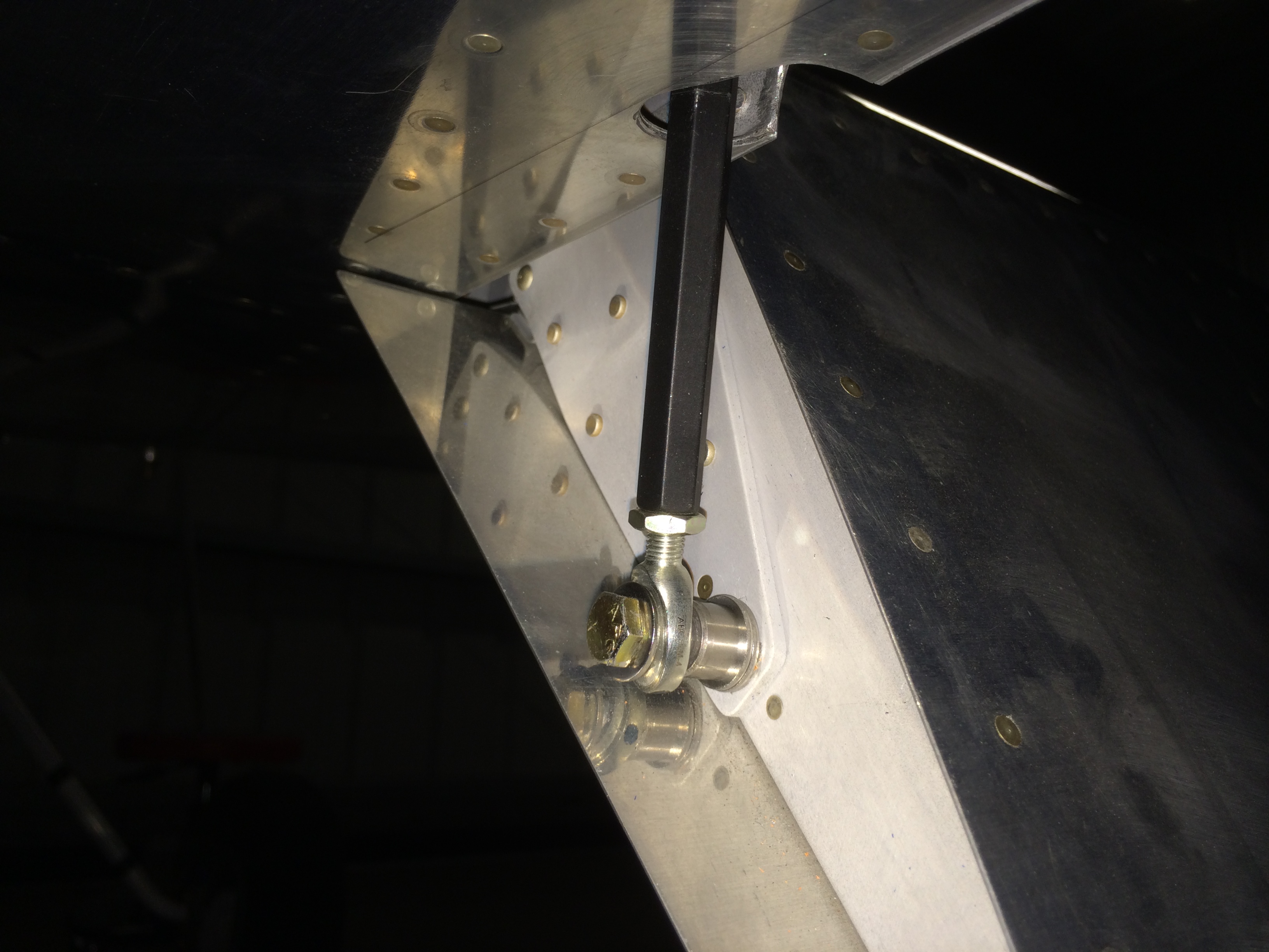
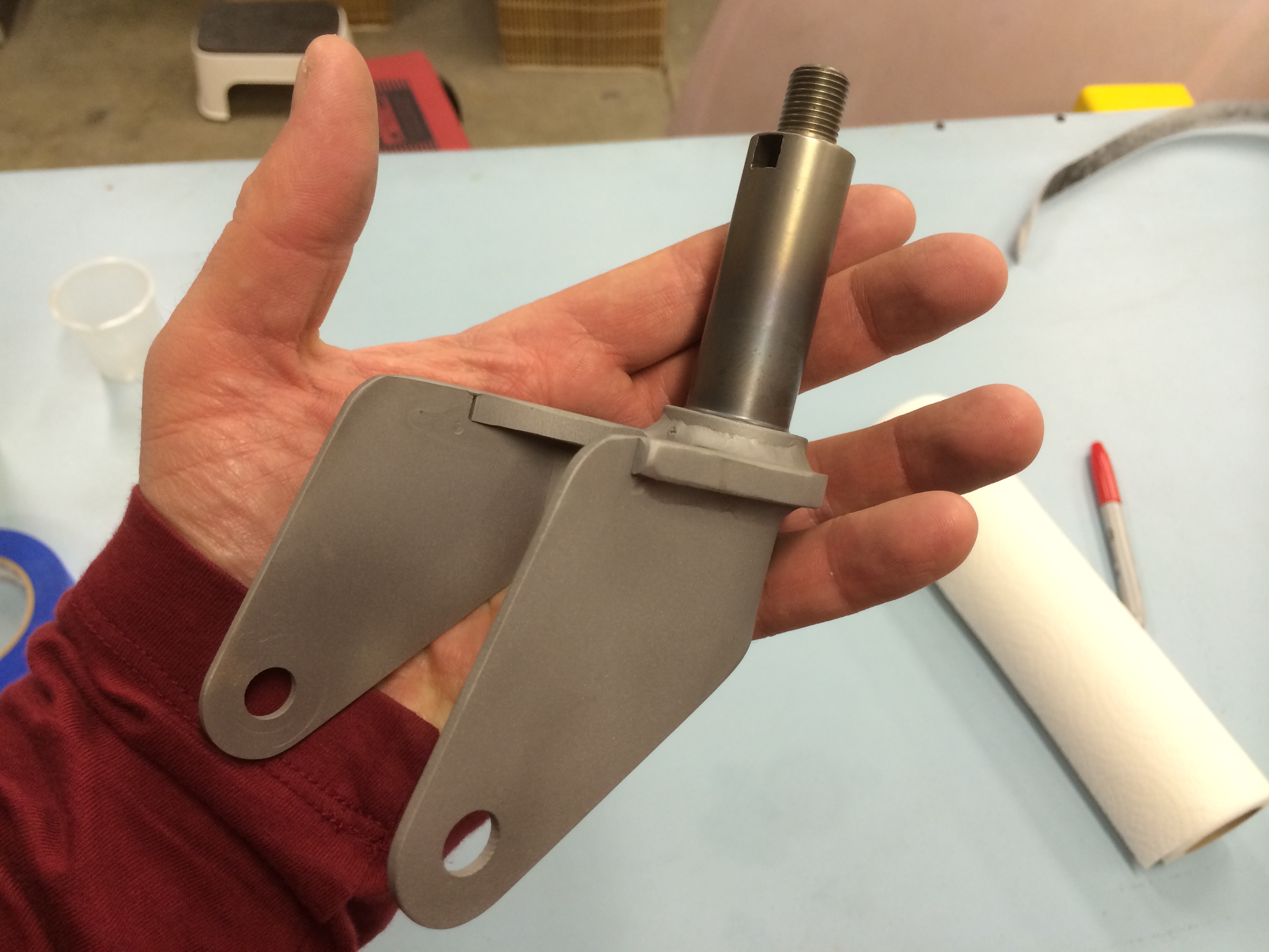
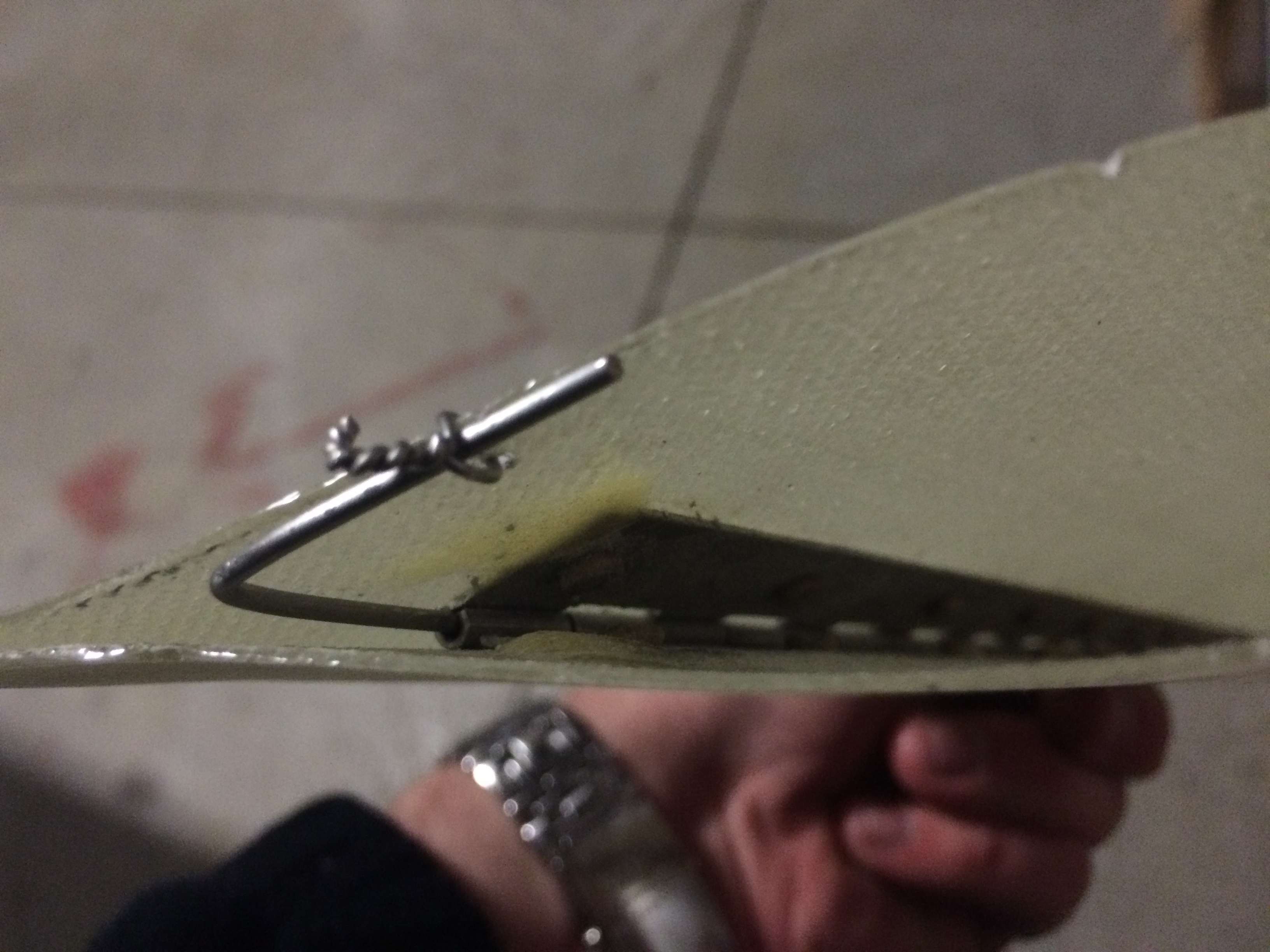
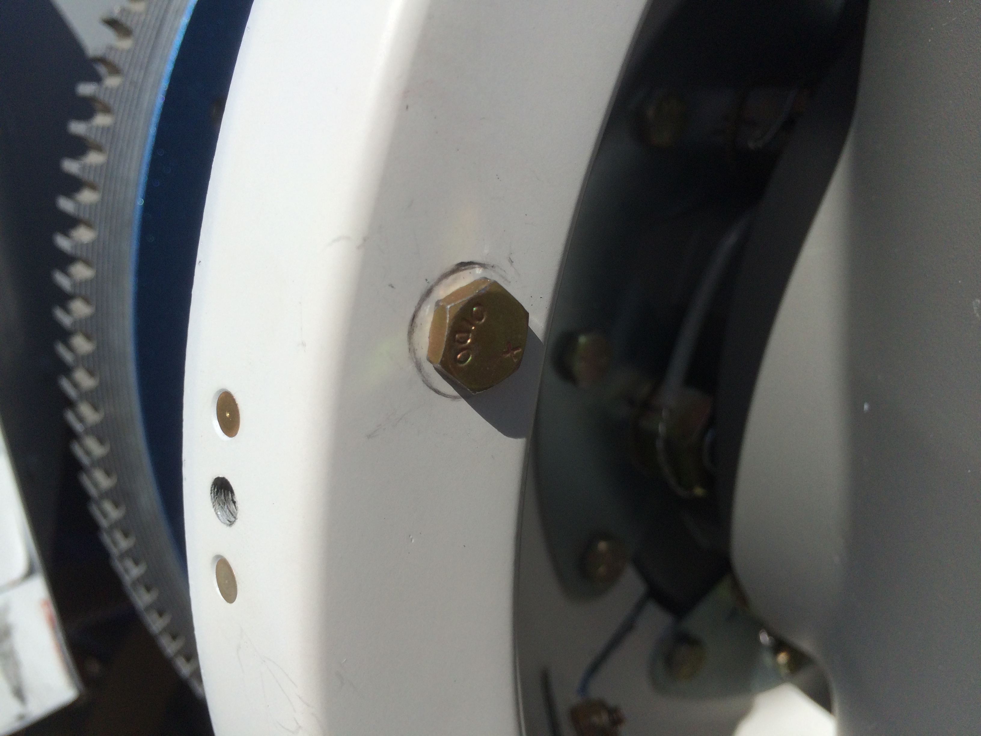
The DAR mentioned that he doesn’t like Van’s design for the flap pushrod attachment since the rod could come off if the rod end fails.  Every other rod end on the plane is either captured by the surrounding attach point or has an AN970 washer to keep the rod end together in case of bearing failure.  The failure of a rod end can be a catastrophic failure since a split flap condition can cause a violent rolling motion.  Since full flaps are usually used on final approach when low and slow, a failure here could be fatal.  By switching to a regular rod end from the ball joint linkage supplied in the kit, you can prevent the joint from ever coming apart.

Fortunately, my friend Greg had already warned me that the DAR would like the see these parts upgraded, so I had the parts in hand.  I also upgraded the pushrod from the one I made to the one sold by Avery Tools.  I still need to adjust the pushrod length to get the flaps back into alignment with the ailerons, but I’m much happier with this arrangement.

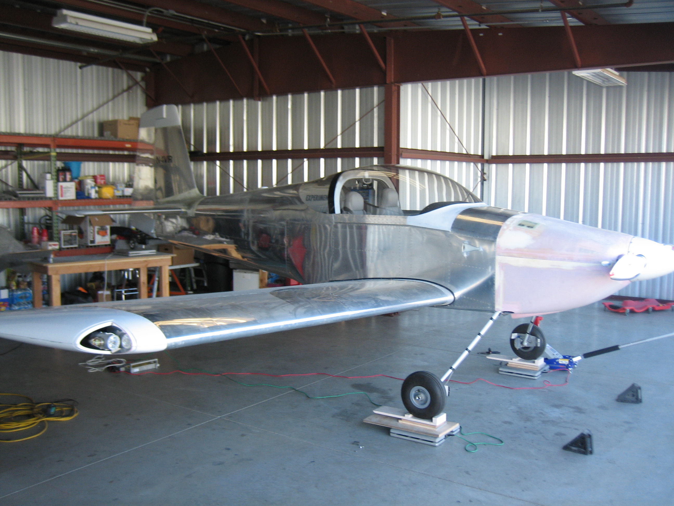
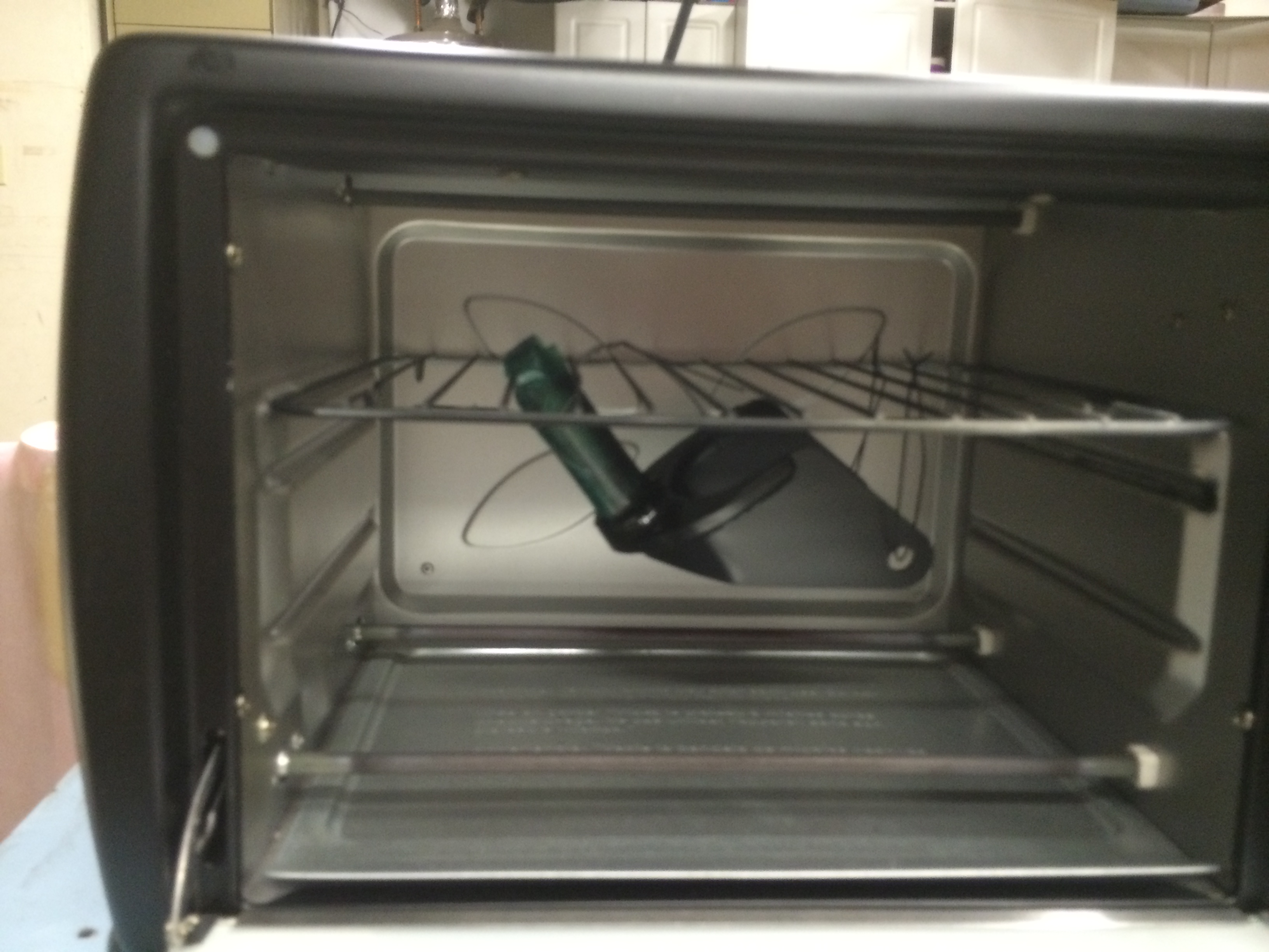
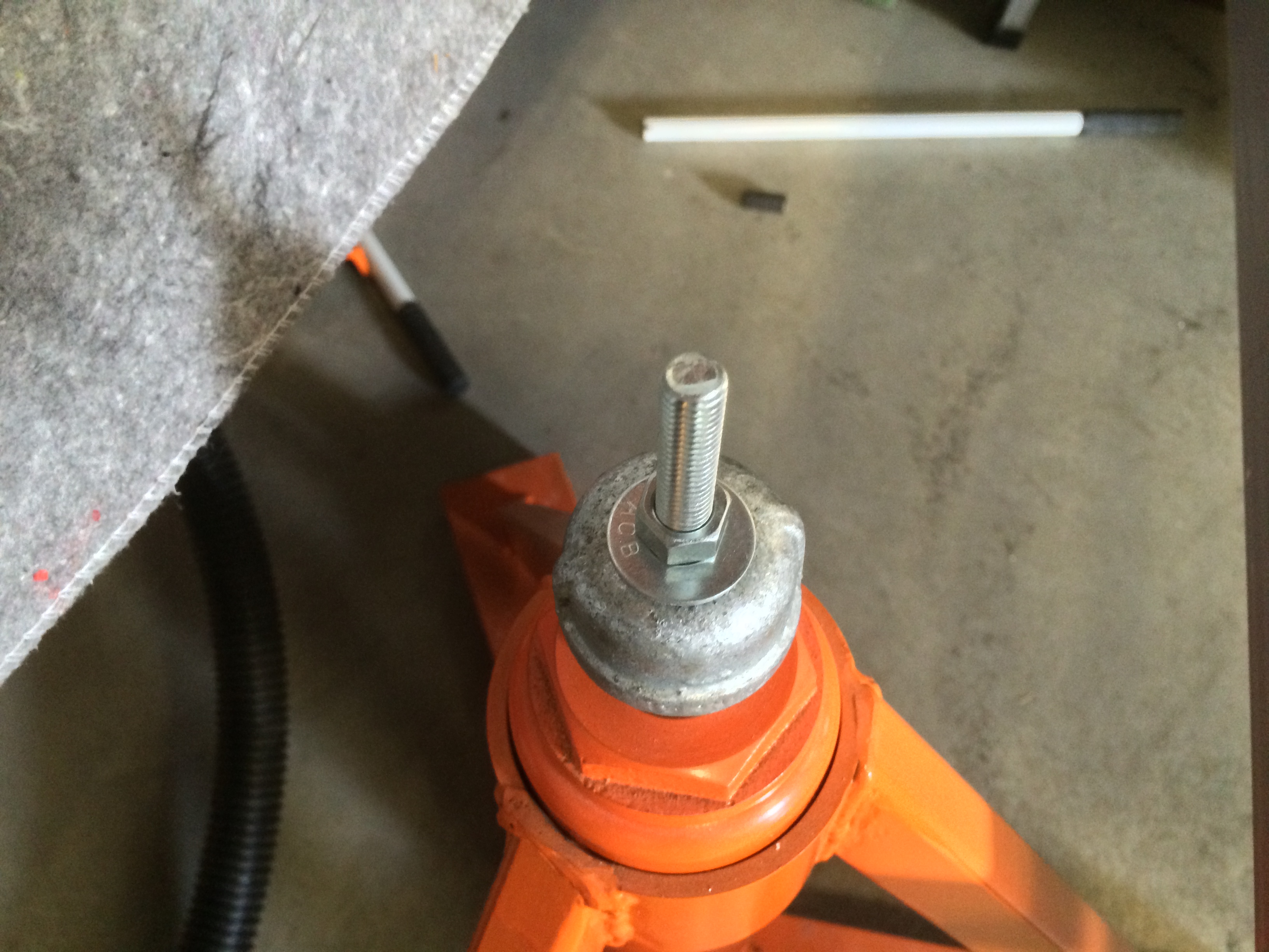
Since my CG ended up farther back than I was hoping, I’ve been looking for ways to move it forward.  I purchased the Bell tailwheel fork a long time ago since I really dislike the Van’s design.  I didn’t realize at the time how much heavier it was though.  While researching other options, I found that the tailwheel fork sold by JDAir was even lighter than Van’s.  I haven’t measured for myself yet, but they told me that I should save about 1 pound from the Bell fork.  This doesn’t sound like much, but with an arm of over 249″, this change alone will move the CG forward by over 0.15″.  The fork comes plain or powder coated in either gloss white or gloss black, but I previously powder coated all of my tailwheel components in matte black, so I ordered it plain so that I could match the finish.  I stopped by the TechShop earlier today and smoothed out all of the edges and then sandblasted the areas that will be powder coated.  That produces a nice textured finish that the powder coat will stick to nicely.

I applied the powder coat and then baked it in the oven for about 20 minutes at 350º.

Riveted Hinge to Right Gear Leg Fairing

I wasn’t able to spend much time at the hangar today, but I did get down there for a bit in the afternoon.  The winds were way too strong to fly (at least until I get more practice in the plane), but I did get a chance to resume work on the gear leg fairings.  I had previously trimmed them to size and put strips of tape along the aft edge as reference points to ensure they’re straight.  I then clamped the trailing edge with some cleco clamps and drilled the hinges to the inside of the fairing.  After countersinking, I removed the hinge and deburred it.  I used some of the G/flex epoxy from West Systems to bond the hinge halves to the inside of the fairing and then riveted into place with some soft rivets.  I only had time to do the right fairing today, but hopefully I can knock out the other one tomorrow.

I had been planning on fabricating some jacking points for a while now.  Even though I’m going to lift the plane by the engine mount using the shop crane I bought, I need something under the wings to keep the plane from swinging.  Since I fabricated aircraft jacks awhile ago, using them to support the wings seemed like the best plan.  I bought some 1″ galvanized pipe caps and drilled them for a 3/8″ bolt.  I then inserted a 2″ long 3/8″-16 bolt through and tightened it down with a washer and nut.  This is screwed all the way down to the stop I installed in the wing tie-down point.  I might trim about 1/4″ off the bolt to reduce the bending load a little further.

The cap just fits over the end of the ram on the jack.  It has just enough room to move around that I can insert it over the ram without having to be perfectly aligned with it.

Riveted Hinge to Left Gear Leg Fairing and Flight Testing

I wrapped up the hinge on the other gear leg.  I’m probably going to end up shortening these since they’re a bit longer than necessary.  I need to fabricate the clamping pads at the top of the fairings, and then I can align them to the longitudinal axis of the plane.

The clouds lifted enough in the afternoon that I could take the plane up for another flight.  I took the opportunity to calibrate the AOA system.  On the SkyView, this is done by doing a series of stalls in various flight configurations and hitting a button on the EFIS each time.  I also took the plane up to 8,000 ft to measure the true airspeed.  I’m still slow because the wheel pants and gear leg fairings are not installed, but I saw 162 kts.  I expect to be near 175 kts after the fairings are installed.

I also intentionally ran my right tank dry in flight so that I can do the final fuel gauge calculation. The SkyView system annunciated “fuel pressure” just a second or two before the engine started stumbling.  I switched tanks and hit the boost pump, and the engine surged back to life within 3-4 seconds.  The experience was very different than when I’ve run a tank dry in my Bonanza.  In the Bonanza, the engine power winds smoothly down with no surging or stuttering.  After changing tanks, the power winds smoothly back up.  In the RV, the power loss was much more abrupt and there was quite a bit of stumbling before power was smoothly restored.

Glassed One Side of Gear Legs

I wanted to lay up a thin layer of glass over the rivets holding the hinge material to the gear leg fairings.  I used a couple of strips of the lightest cloth I had on hand and covered them in some Dacron (which is what you see here).  I’ll do the other side of these soon and then I can put a thin coat of filler on the fairings.

Glassed Other Side of Gear Legs

No pictures tonight since it would look identical to last night, but I glassed the other side of the gear leg fairings.  I also stripped off the peel ply from last night and trimmed the excess epoxy.  I’ll need to sand down a few high spots before applying the filler.

Restored Airplane to Flight Status

Since I had the aft baggage wall out to adjust the ADAHRS, I took the opportunity to inspect all of the elevator linkages and relubricate them.  I then vacuumed out the entire fuselage.  Despite doing this thoroughly before first flight, there was an amazing amount of debris including a large number of small metal particles from the drilling operation when assembling the fuselage.  I have no idea where these particles were hiding when I earlier cleaned out the fuselage.  I then reinstalled the aft baggage wall and all of the interior.

Before reinstalling the cowl, I adjusted the prop RPM again to hopefully get pretty close to 2700 RPM.  I also wrapped the fuel flow sensor with some extra thick fire sleeve and some safety wire.  It’s not the prettiest wrap job, but I’ll redo it if works.

Worked on Gear Leg Fairings

I spent a couple of hours down at the hangar tonight, working on the gear leg fairings.  I bent the hinge pins and then spent some time installing them and removing them from the gear legs to make sure I could get the pins in and out fine.  I then drilled a hole in the top of the fairing so that the pin can be safety wire in place.

Dynamic Propeller Balancing and Fairings

Lee Apaka flew down this morning to balance the propellers for Greg and I.  Since I’m running at 2500 RPM with wide open throttle, we tied the plane back to the car and chocked the wheels.  Greg and I both have really smooth engines (a testament to how well Aerosport Power builds then), but they can always be better.  Greg started out at 0.35 IPS (inches per second), so Lee added 17g of weight (a bolt and some area washers) to the spinner backplate.  Amazingly, he nailed it on the first time and hit 0.02 IPS.  Anything under 0.1 IPS is pretty good, and 0.02 is somewhere between excellent and perfect.

After Greg wrapped up his run, I pulled my plane into position and Lee hooked up his gear.  I was only at 0.12 IPS when we started, so I was already a bit better.  We added 5.9g to my spinner backplate and ran it again. That dropped me to 0.11 IPS.  The formula wanted another 6+g mounted just a few inches away from the first weight.  Lee decided instead to add one more washer and a slightly longer bolt.  I did a third run and hit 0.02 IPS.  I’m super happy with the results.

Here’s where the weight was added to the spinner backplate.  There is a washer and an AN364 nut on the other side.  Our fix was to add one additional washer under the head shown here.

I jacked up the plane and started working on the gear leg fairings.I laid up some additional fiberglass inside and then mixed up some epoxy/flox mixture and gooped it around the line where the fairing will sit against the gear.  I then started working on the wheel pants.  With the fuselage level, I supported the rear of the fairing to get the center 8 5/8″ from the ground while simultaneously adjusting the fore/aft position so that the outer support bracket edge lines up with the step in the fairing.  I then drilled it to the outer fairing.