Started Wiring Interior Lights

I spoke with Dynon this morning and they were already aware of the reverse trim issue.  The fix will require software updates to both the Dynon SkyView and the VP-X, but those aren’t out yet.  It’s not blocking anything for me right now, so I’ll just wait for the updates.

I moved ahead and finished the power and ground wires for the seat heaters.  I *think* this will be the last ground wire that attaches to the firewall ground block.

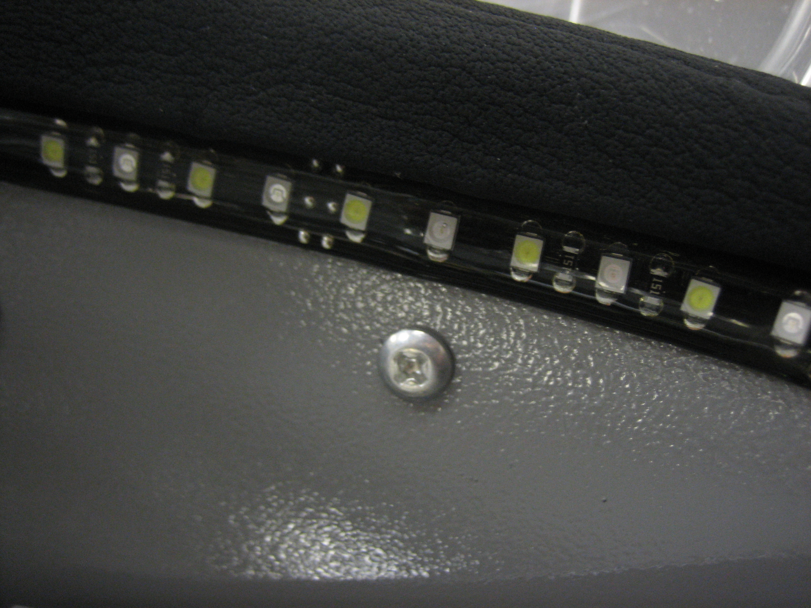
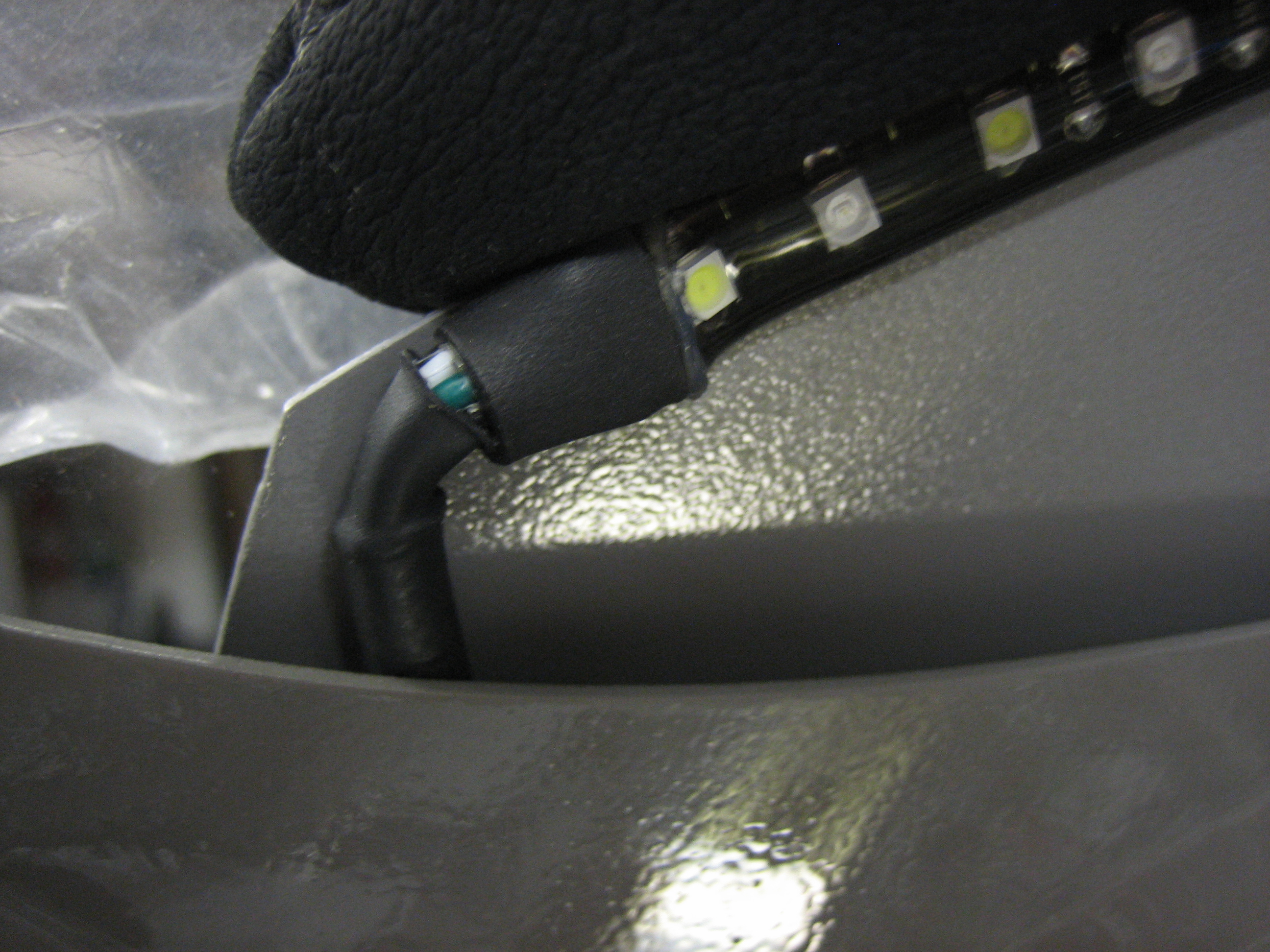
Next up, I started wiring the interior lights.  I had been planning on wiring the cabin lights (in the roll bar support channel) directly to the battery bus so that I can turn them on without turning on the master switch.  I originally ordered a linear dimmer module from Perihelion Design.  This has the nice feature that when the knob is turned off, the dimmer draws absolutely no power.  A while back though, I decided to switch to a PWM dimmer from pilotlights.net.  The dimmer provides a much smoother and more linear brightness ramp, but unfortunately, it draws between 6 and 13 mA even when the output is open.  At 13 mA, that would completely drain my battery in ~54 days, but it would drain enough power to affect starting in quite a bit less time.  I don’t really see a way around this since the dimmer has to be connected prior to the switch that routes power to either the white or green cabin lights, so there’s no way to shut off power to the dimmer if it’s wired directly to the battery bus.  I’ve decided to just move the cabin lights to the interior lights circuit on the VP-X.  This will eliminate the current drain, but will unfortunately mean I will have to turn on the master switch to turn on the cabin lights.

Worked on Interior Lights and Seat Heaters

I wanted to make some more progress on the interior lights, but I first needed to determine if I have to shorten the LED light strip that will illuminate the glare shield.  Although the light strip is shorter than the edge of the glare shield, I wanted to make sure the end lights weren’t visible since the glare shield curves down on each end.  In order to determine that though, I needed to install the glare shield trim.  I determined the centerline and clamped the template in place to mark the holes.

I then drilled the holes and mounted the glare shield trim.  This is padded and has a nice french seam on the facing edge.  I then sat in the plane to determine if the trim will hide all of the lights in the LED light strip.  Fortunately, it does and I can go ahead and install it.

I determined the centerline of the light strip and then adhered it in place.  I’ll paint these mounting screws to match the surrounding surface before installing the trim permanently.

On the left end of the light strip, I installed some nylon sleeving and heat shrink tubing and then tucked it behind the brace.

I used some E6000 to adhere the cable in the channel.  The cable will exit the canopy through a hole in the brace that I need to drill.

I used some popsicle sticks and tape to hold the cable down in the channel while the E6000 cures.  I’ll finish routing the wire after that.

I decided to get back to the seat heater wiring.  I need the cables coming from the seats to be easily removable whenever the seats are removed. I picked up some power jacks from Radio Shack and wired up a couple of these adaptors.

I then drilled a couple of 5/16″ holes in the inboard seat ribs and seat pan on both sides.

Here is the adaptor installed.  I then ran the wires for the right seat heater, hooked them up and verified proper operation.

I’ll use these corresponding plugs on the ends of the cables coming from each seat bottom and seat back.

Installed Left Seat Heaters, Finished Glare Shield Lights, Installed Vent Ducts

I finished running the wires for the left seat heaters.  I had to pull the pushrod back so that I could install a few zip-tie bases to anchor the wires to the seat rib.

I drilled a hole for the glare shield wire bundle and installed a rubber grommet.  I installed another zip-tie base to secure the wire next to the fuel sender and installed the rest of the wires to the dimmer and panel ground block.

I meant to install the vent ducts earlier to ensure that nothing interferes.  Unfortunately, I ran the pilot’s side headset wires right through the duct path.  They’re not long enough to route over the duct, so I’ll have to route them under it.  It’s not that big a deal, but you should install these as soon as the panel goes in to avoid running into any interference later.  Most things have some flexibility about how they’re routed, but these can pretty much only run here.

Reverse Trim Control Resolved

Vertical Power released version 1.3 of their VP-X firmware today.  I installed it and it resolved the issue with the reversed trim buttons on the SkyView.  Now, whether I press the coolie hat on the stick to the right or press the “Right” button on the SkyView, the stick goes right.

I spent the rest of the night messing around with the oil cooler position.  I think I’m finally pretty happy with the location.  I ended up turning the oil cooler over from the way I had it so that the oil cooler hoses attach on the bottom.  With the oil cooler mounted on the baffles, it’s higher than the oil return line on the engine, so oil drains out of the oil cooler automatically during oil changes.  With the oil cooler mounted on the engine mount or firewall, it’s below the oil return line, so most of 1 qt of oil would be trapped in the oil cooler during oil changes.  I did some research on this, and this is not too uncommon on certified airplanes, and the way to deal with it is to make the oil hoses enter from the bottom and put a tee in the lowest fitting.  One side of the tee will go back to the engine, and the other side will just contain a cap.  During oil changes, this cap can be removed to drain the oil out of the cooler and hoses.

Ran Copilot PTT Wires

I spent most of the night cleaning out the garage and organizing my wire drawer (it had become a real rats nest), but I did manage to secure the copilot’s wire bundle to the adjacent rib and install a molex connector at the end.  I snaked the wires on the other side of the connector up behind the panel and over to where the copilot’s headset jacks are installed.

Received Servo Back From Dynon

When I purchased the autopilot servo to install in the wings, Dynon had not yet announced that it couldn’t be updated to work with the SkyView without using one of the first gen products.  Even after they announced that, I thought for a long time that I would be using a D6 as my backup EFIS and could update the firmware with that.  Once I decided on using the TruTrak Gemini instead, that meant I needed to have Dynon do the firmware update, so I mailed my roll servo back to Dynon last week and got it back today.  I’ll get my wings back tonight and reinstall it soon.

Installed Connector on Roll Servo

I picked up my wings from my next door neighbor where he’s graciously stored them for the past nearly two years.  I’m going to be mating them to the fuselage in about a week.  Since I’ll be moving to the airport in a few months, I’ll probably just end up storing them on the side of my house till then.

I installed a male DB-9 connector on the end of the wires from the roll servo.  I took this picture mostly to document the wire positions in the connector.  Not easily visible is the black wire that is connected to pin #2 (straight behind the red wire and just to the left of the green wire).

Here’s the finished connector with some expandable nylon sleeving over the bundle.

Installed Roll Servo and Canopy Switch

I reinstalled the roll servo and torqued/safety wired the bolts.  I then temporarily hooked up the servo to the SkyView network and calibrated it.  I’ll have to redo the calibration once the wings are on, but everything seems to be working properly.

I installed a small microswitch to sense when the canopy is latched.  The switch is only activated when the latch finger is rotated back and the catch is in place.  I ran a wire from the annunciator control circuit back to here.  It will be grounded locally when the switch is open.

Finished Fuselage Wiring and Fabricated Flap Pushrods

I hooked up the canopy switch wires and verified the annunciator light illuminated appropriately.

I attached the ground wire to one of the canopy latch pivot block mounting bolts on the back side of the bulkhead.

I also installed a connector and some zip-tie bases in the roll bar support channel and hooked up the cabin light.

Finally, in preparation for mounting the wings this Friday, I fabricated the flap pushrods.  I cut the tubes from some 5/16″ stock with 0.058″ wall thickness and then drilled/tapped the ends for the 1/4″-28 bearings.

Annunciator Control Circuit (Version 2)

I mentioned a few weeks ago that there was a flaw in my annunciator control circuit.  I redesigned it to provide a pull down resistor for the transistor base and a pull up resistor for the transistor collector.  I received the circuits yesterday and quickly assembled one, but it was not working as expected.  It was late, so I put it off until tonight.

I got started tonight trying to diagnose the misbehaving circuit.  The first three annunciator lights were working as expected, but all of the others (both some high and some low triggers) were misbehaving.  I measured the voltages at various points in the circuit, but they really didn’t make sense.  It was almost as if I had installed PNP transistors instead of NPN transistors.  I checked the bag from Radio Shack and they were indeed NPN.  I breadboarded a single light control circuit and still couldn’t get it to work properly.  At this point, I was beginning to wonder if I had completely forgotten my circuit design skills from university.  I was disassembling the breadboard circuit and noticed that the transistor was smoking hot.  This shouldn’t have happened because the transistor should either be fully off or fully saturated.  In either case, the power dissipated in the transistor should have been essentially zero.

It was really starting to seem like the only explanation was that it was a PNP transistor.  I looked up the part number on the transistor, and sure enough it was a PNP.  I went through the whole bag from Radio Shack and sure enough, every transistor was a PNP despite the bag indicating they were NPN.  I started desoldering the transistors off of the board and noticed the first three (the circuits that worked) were NPNs that I had left over from the first circuit I built.  This really pissed me off.  I wasted hours trying to diagnose a problem caused by Radio Shack’s mislabeled transistors.

Anyway, I replaced all of the incorrect transistors and unsurprisingly, the circuit worked flawlessly.  All of the annunciator lights have nice sharp on/off transitions and work exactly as expected.