Rudder Fully Assembled

I still haven’t received an email back from Van’s about the top rib, so I gave them a call.  They’re going to take a closer look at my pictures and get back to me, but they did say that the top rib often requires a bit of massaging by the builder to get everything to line up.  Since I may end up using this rib anyway, I spent some time tonight getting it bent such that all of the holes lined up and the skin laid flat against its flanges.  Here is the rudder fully assembled to see how things lined up.

Here is the tip of that rib after I adjusted it a bit.  The holes line up well enough now that the clecos interfere with each other (causing the top one to lay over a bit).  I still have to adjust the fluting a bit more (you can see a slight gap between the skin and rib where the second cleco in on the top is located).

I went ahead and trimmed the rudder brace and fitted it to the rudder horn.

Finished Drilling Rudder

This looks a lot like the picture from yesterday, but now the rudder has been fully drilled and is ready for disassembly and prep for riveting.


After disassembling, I drilled the rudder counterweight to the R-912 counterbalance rib, dimpled the rib and countersunk the lead weight to accommodate the dimples.


You have to make the rudder bottom attach strips from a piece of 0.032″ alclad.  Basically, you just cut these to 18″ and trim the corner as specified.


Here are the strips, temporarily clamped to the R-904 bottom rib to match drill with the existing holes.  Holes in the lower half of this strip will be drilled in conjunction with the fiberglass rudder bottom.


The R-913 counterbalance skin in 0.032″, and because the rudder skin is 0.016″, the overlap can cause a visible joggle in the rudder skin.  Beveling the two points on each side of the counterbalance skin where these two skins overlap with the underlying structure smoothes out this transition.

Prepped Rudder for Riveting

In order to dimple the rearmost holes on R-903 and R-904 (top and bottom ribs respectively), I broke out a tool I made while building the practice control surface from Van’s.  It’s basically just a small piece of steel that’s been drilled and countersunk for #30 and #40 drills.


Here you can see how it’s used.  The rib is slipped over it and the rivet gun is set up with a special rivet set that holds any type of squeezer set.  Here it’s holding the #40 male dimple set.  A few hits with the rivet gun and this creates a nice dimple.


Next up was to countersink the trailing edge wedge.  Unlike the other control surfaces on the RV-7 which use a folded trailing edge, the rudder uses two separate skins that are joined at the trailing edge with this wedge.  This is countersunk from both sides to receive the dimples from the skins.  A rivet is then set against a back rivet set such that it fills the dimples on both sides of the rudder.


One skin fully deburred on both sides.  The RV-7 rudder uses very thin 0.016″ skins, so you have to be very careful when deburring to avoid removing so much material that the inside of the hole has a knife edge.


Here’s the same skin fully dimpled.  I only need to prep the other skin, prep and prime the internal components, and the rudder will be ready to assemble.

Finished Rudder Structure

I deburred and dimpled the other rudder skin tonight.  I highly recommend the DRDT-2 dimpler.  Not only is it quiet and very low impact, there’s basically no chance of damaging the skin.  I can’t tell you how many builder’s websites I’ve run across where they accidentally put an extra hole in their skin while dimpling using the standard c-frame dimpling tool.  Unless you’re completely not paying attention, I simply can’t see how that could happen with this tool.  If you lower the handle gently into the hole and only press firmly after the dies are engaged, you’ll never make a mistake.


The aft three holes at the top on each skin need to be drilled to #30 and dimpled for the rudder top fairing.  The rudder is very narrow here, so there would basically be no access to dimple these after the rudder is assembled.

Rudder Skeleton

I began assembling the rudder skeleton tonight.  First up is to drill out the 3/8″ hole through the lower part of the spar where the lower hinge bracket will attach.


Next is to fit the rudder horn in place and match drill it to the spar.  This view is looking aft from the bottom of the rudder.  The outer holes at the top of the horn will eventually attach to rudder cables coming out the side of the rear part of the fuselage.  The lower holes are for chains that will connect to the tailwheel assembly (though I’ll almost certainly use the rocket steering link).


I started to flute the tip rib when I noticed that the rib is apparently bent incorrectly.  The flange (and therefore hole) on the right side are almost 1/8″ higher than the flange and hole on the left side.  I clecoed on the skin, and this definitely causes alignment problems.  I’ll shoot Van’s an email tomorrow and see if they can send me a new rib.

Began Riveting Rudder

I prepped and primed all of the rudder components.


After the primer dried, I clecoed together the rear spar with reinforcing plates and nutplates for the rudder hinges.


Here’s a closeup of the rudder horn showing the nutplate that will receive the rudder hinge.


Here are the reinforcing plates all riveted on.  The plans don’t include the rudder callout of the nutplate rivets, but you should be able to figure it out by this point.


I couldn’t reach the outer two holes in the rudder horn with any of my squeezer yokes, so I’ll have to shoot and buck those.  It’s too late tonight to make that much noise though.

I could squeeze the counterbalance rib and skin rivets, so I did those.


I also mounted the counterbalance weight.  This required considerable trimming of the lead weight in order to fit between the rivets.  A vixen file cuts through lead like butter though.  This is all torqued and ready to be closed up.

Finished Rudder Skeleton and Riveted Rudder Stiffeners

Jenn helped me shoot the last two rivets (seen here at the far left and right edged inside the rudder brace hole).  Jenn had never riveted before, but she picked it up quickly and did a great job.


Here are the rest of the rivets that hold the rudder brace on.  I managed to get all solid rivets in here without too much trouble.  This would have been nearly impossible without the longeron yoke.  A lot of people wait until the fuselage to order the longeron yoke, but it’s been invaluable on the empennage.  There have already been a number of spots that couldn’t be squeezed any other way.


I riveted all of the rudder stiffeners on this morning before work since I’ve been getting home too late to do it before the kids go to bed.


These rivets are back-riveted which means the rivet gun forms the shop head while the manufactured head rests against a back-rivet place (in this case a large piece of cold rolled steel that I picked up at a local metal supply shop.  Below, you can see the rivet tape that is used to hold the rivets in place until they’re driven.  As everyone says, back-riveting rocks.  The skin is amazingly smooth.


Here is the structure all clecoed together.  Most if not all of the remaining rivets except the trailing edge can be squeezed.  I’ll knock that out tomorrow and then get started on the trailing edge.

Riveted Rudder Skin to Structure

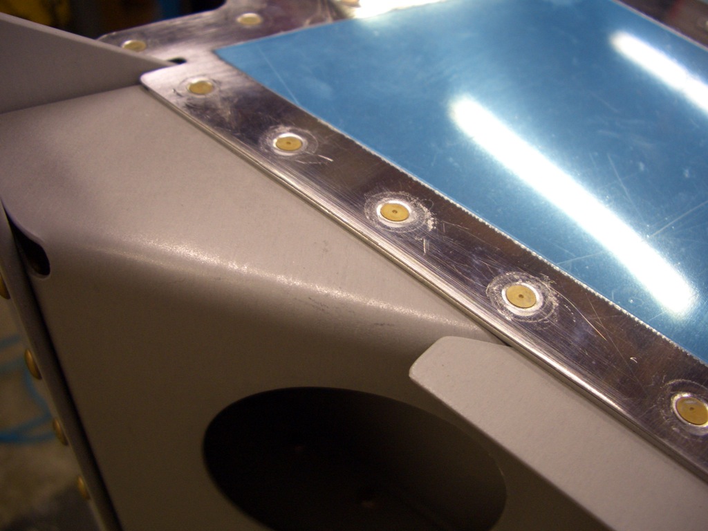
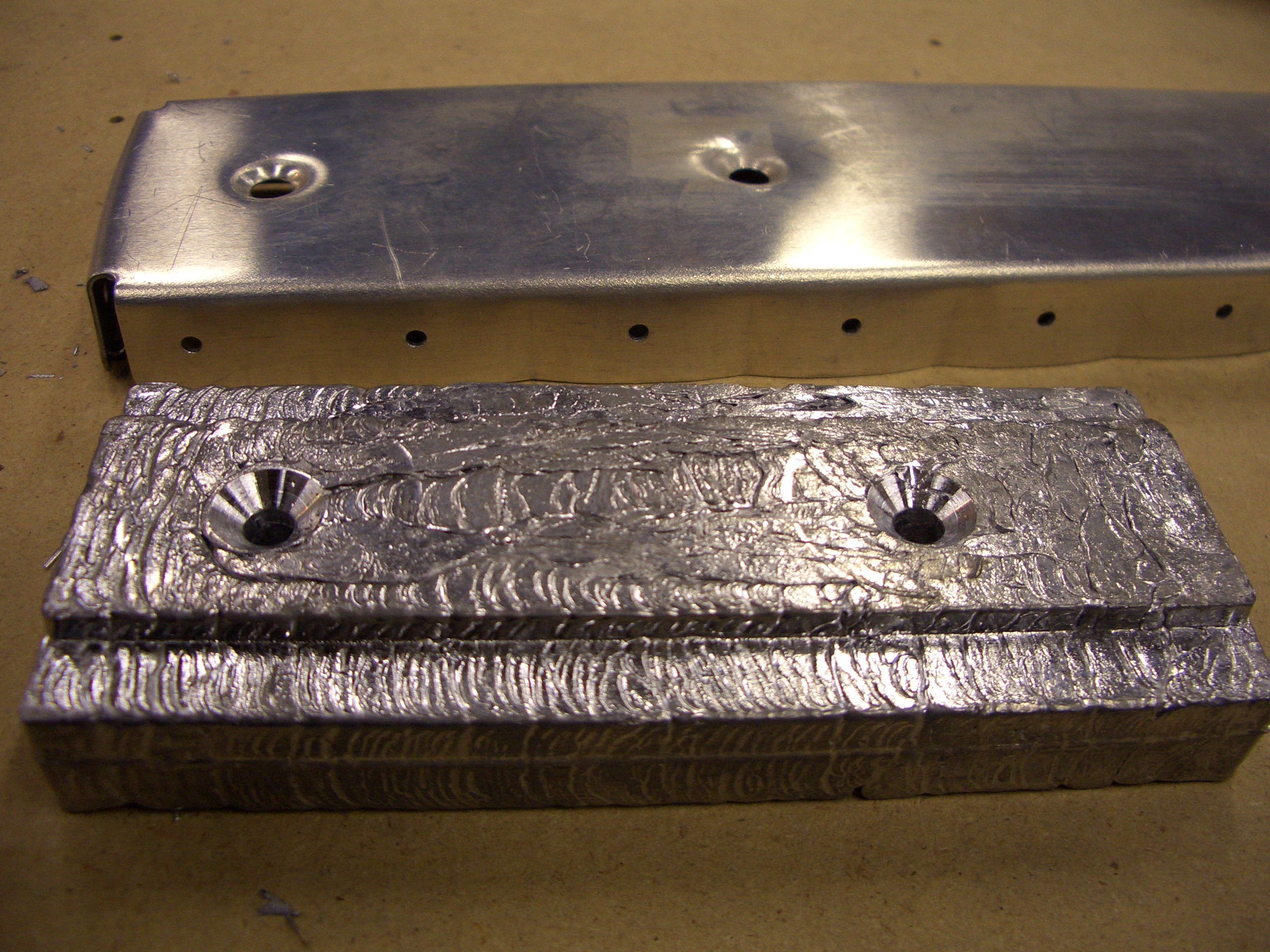
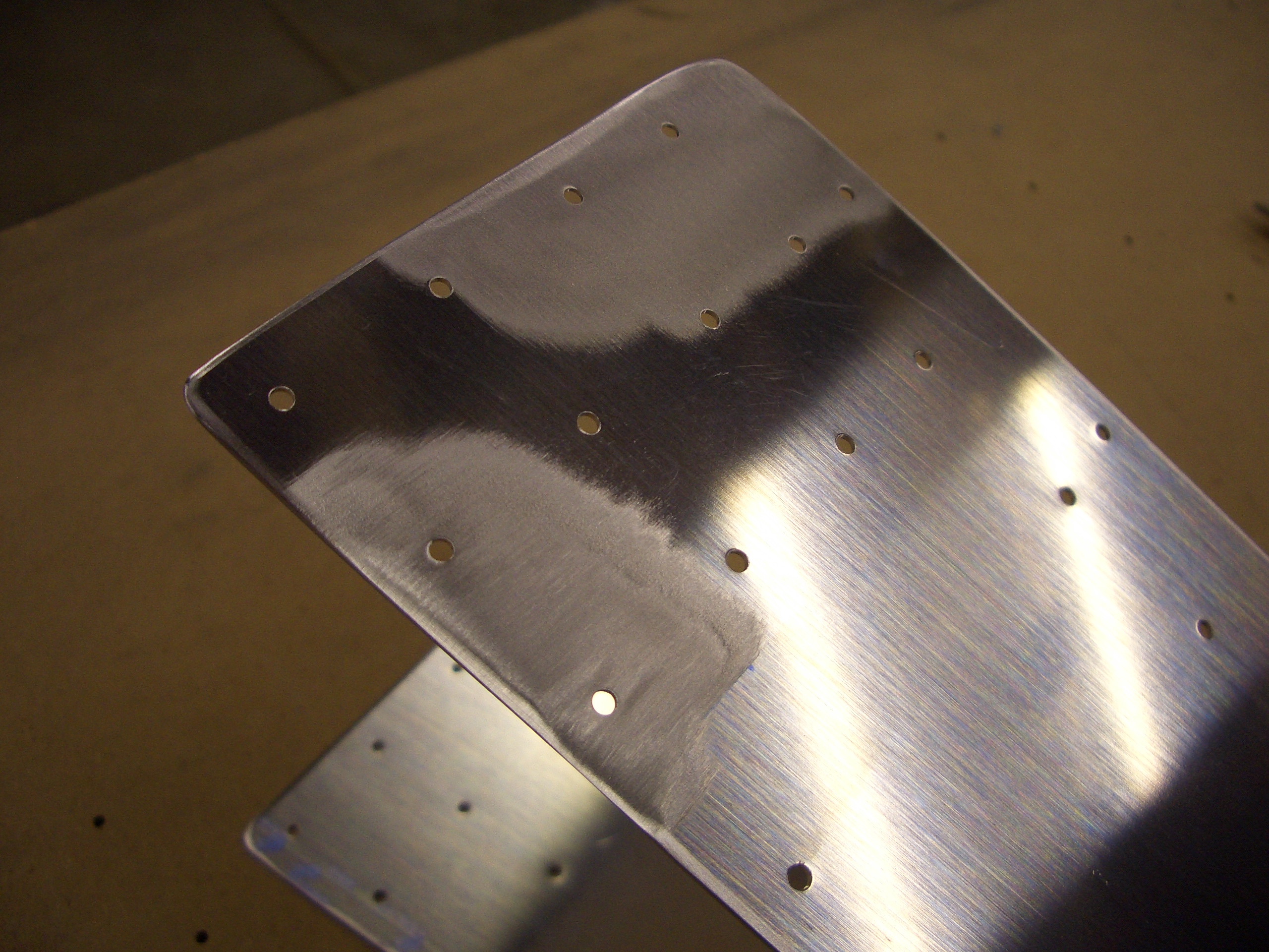
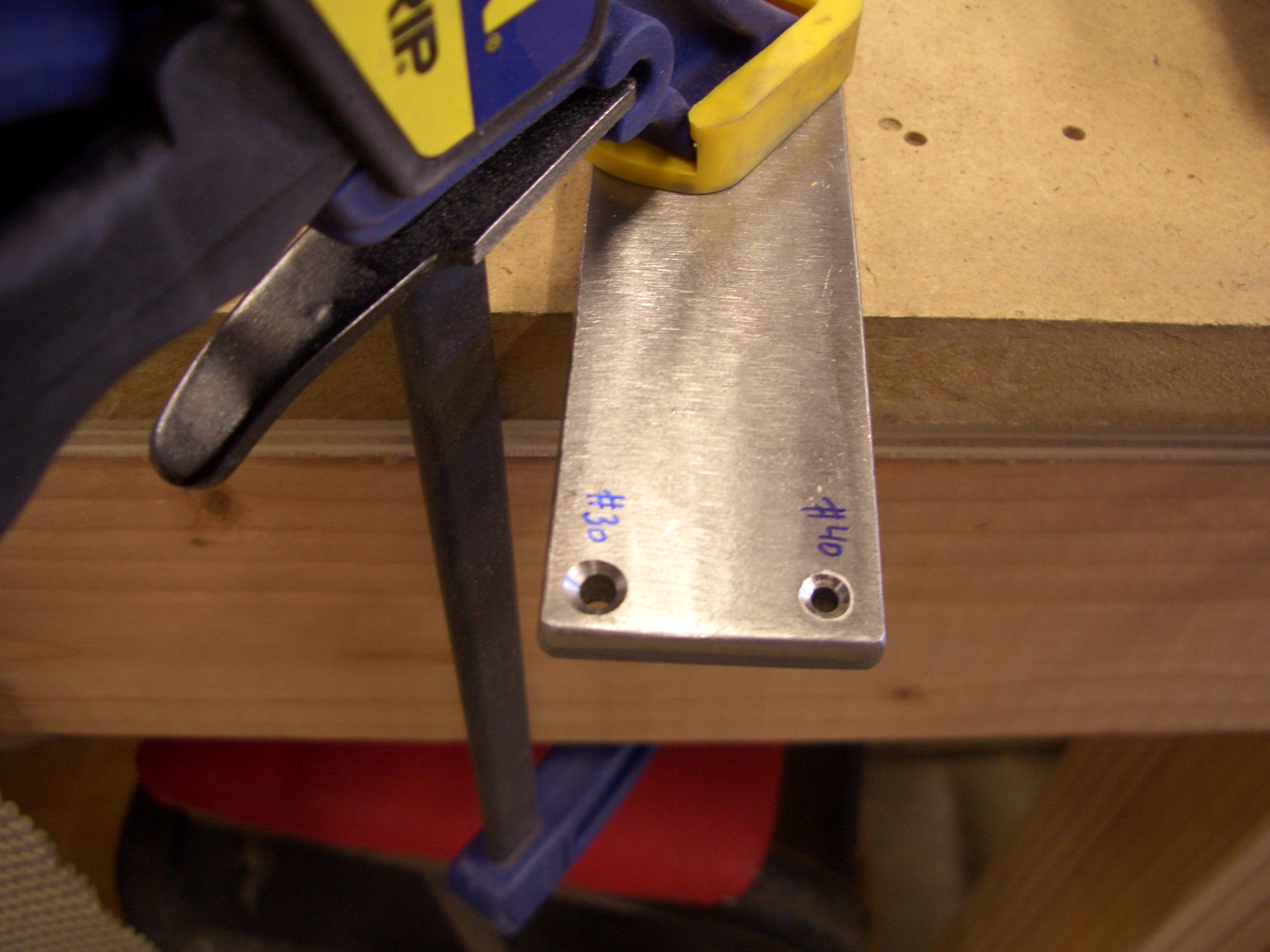
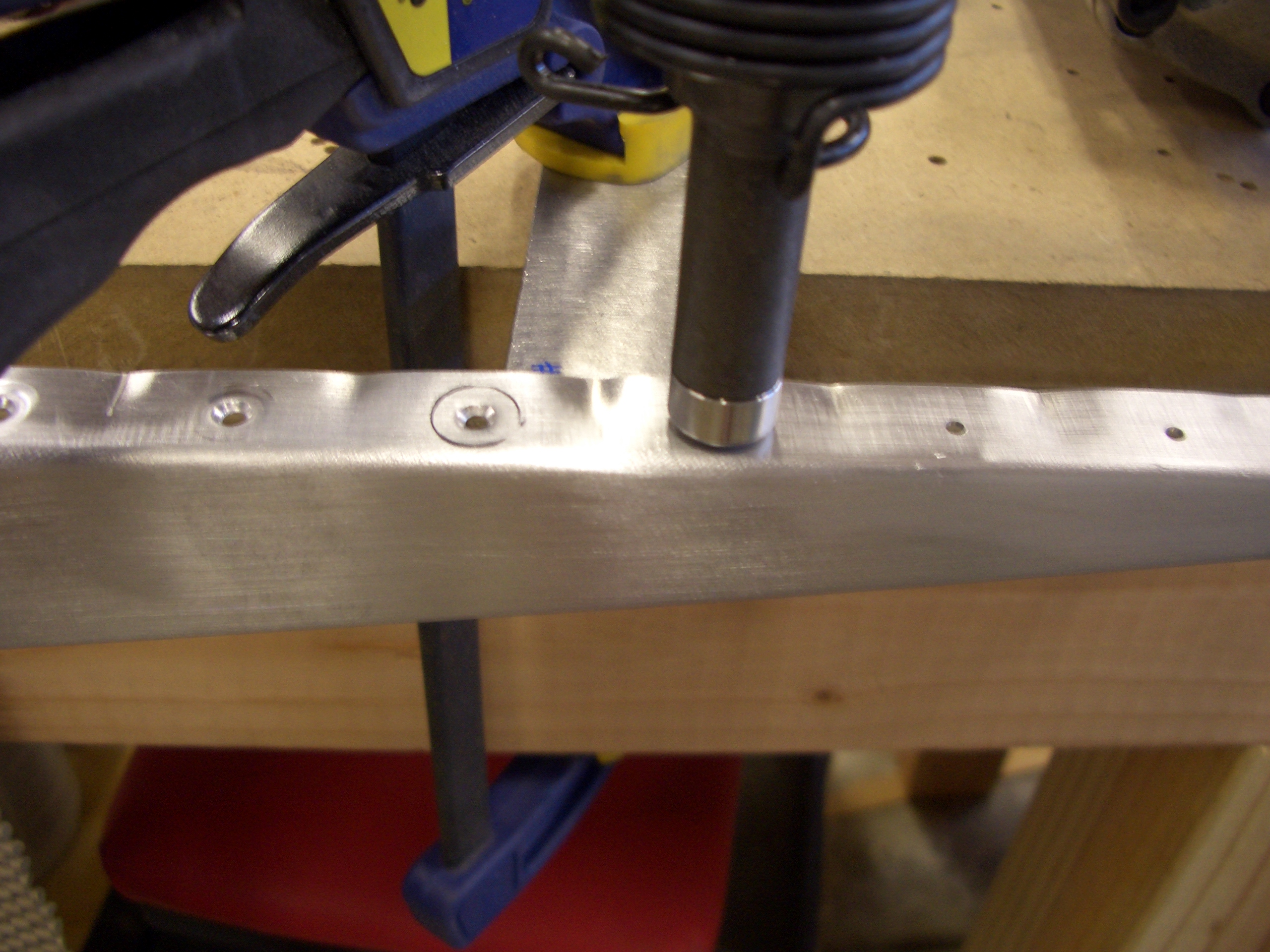
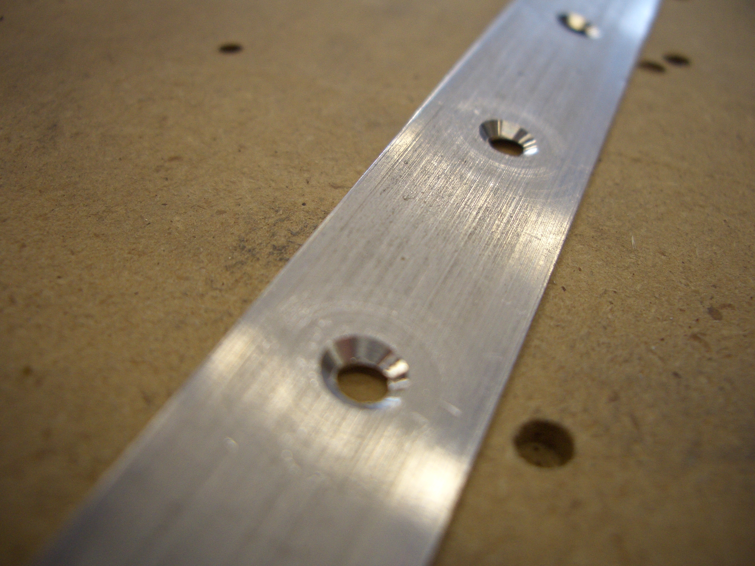
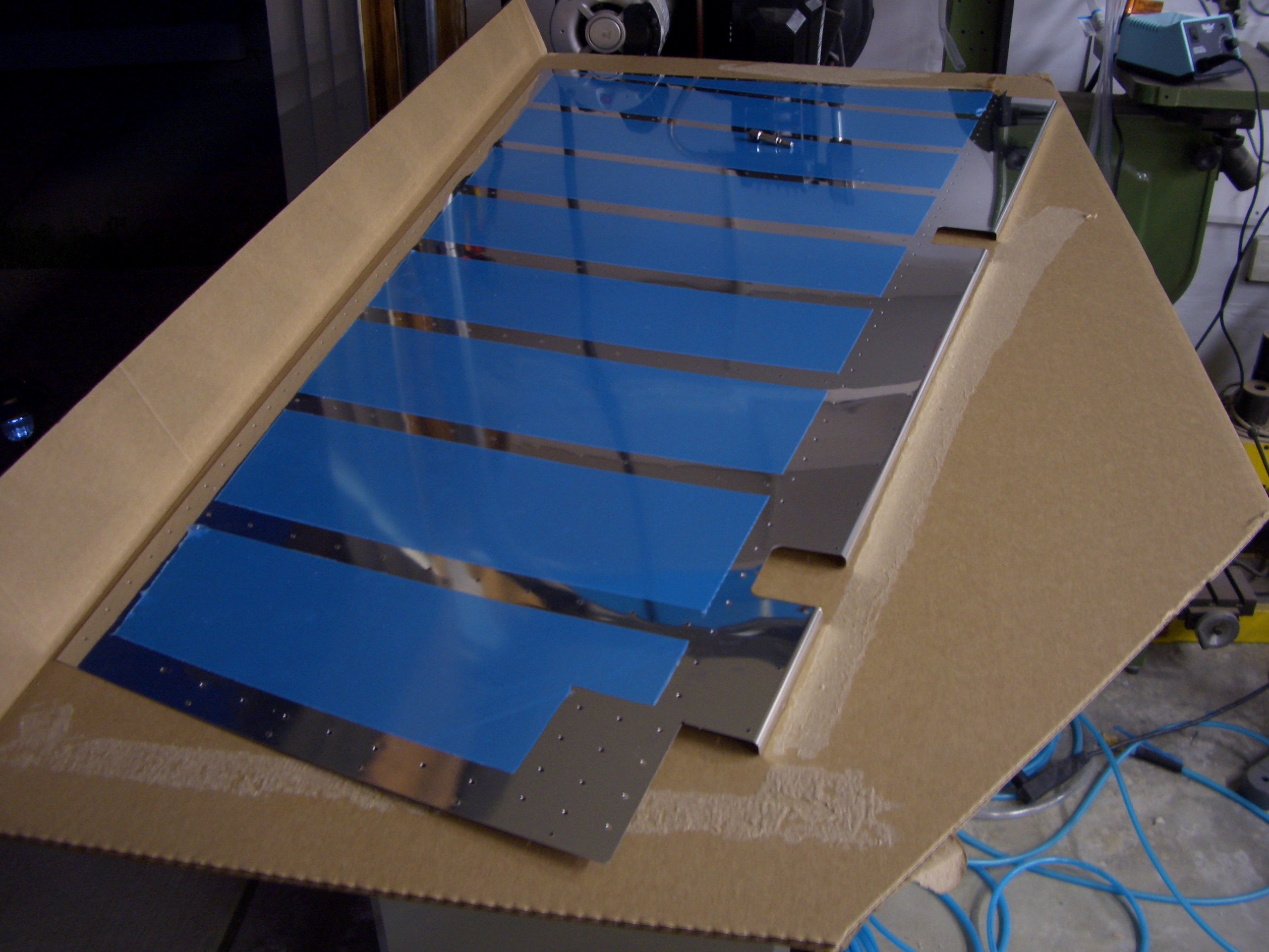
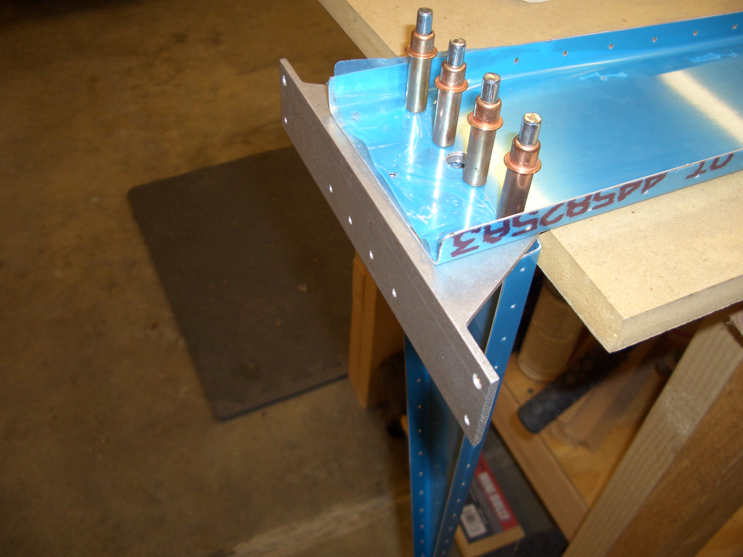
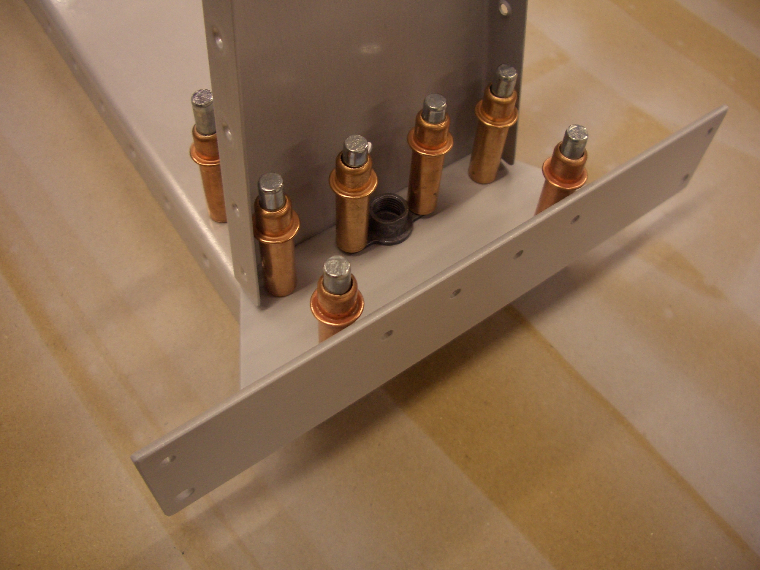
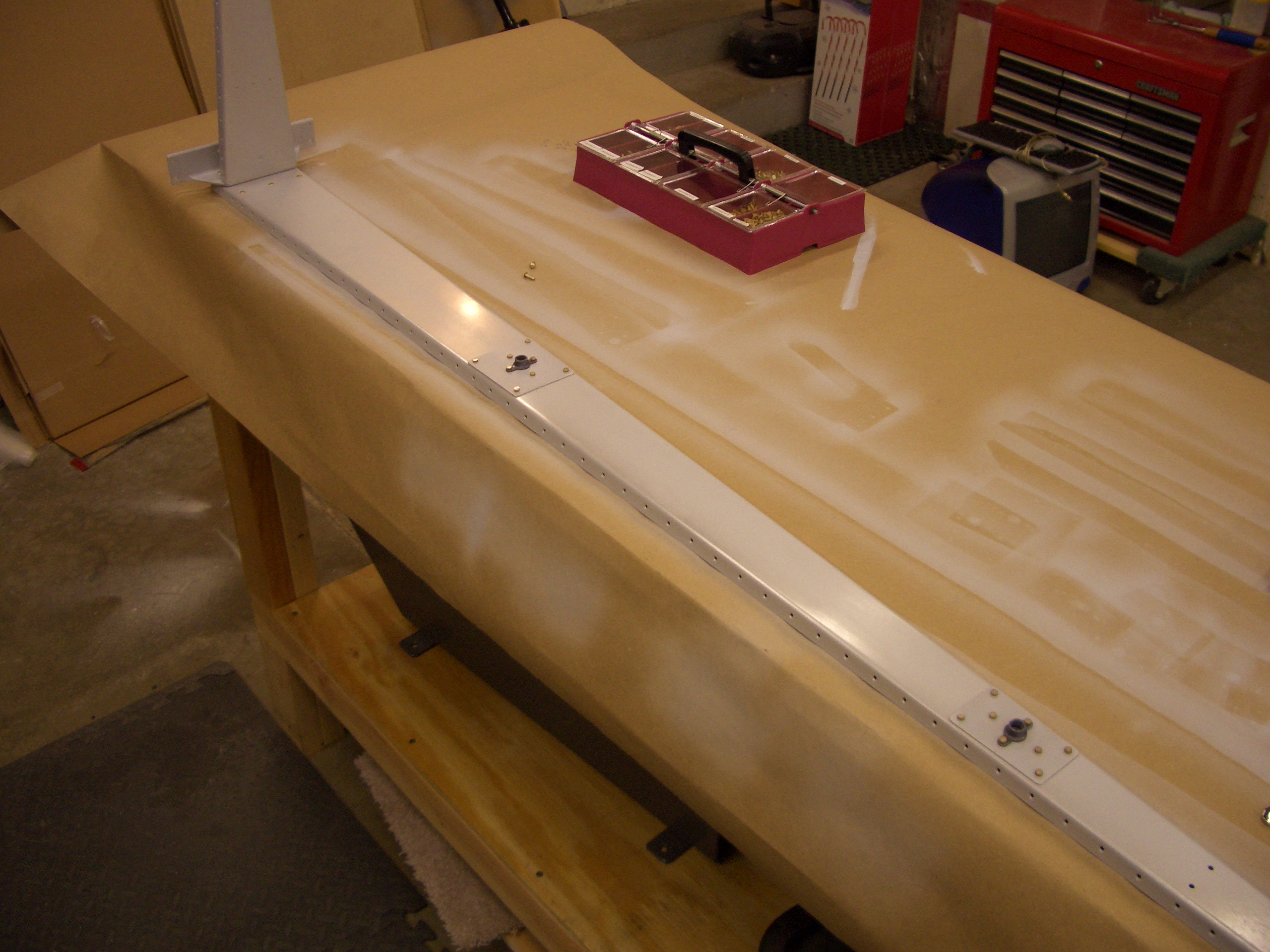
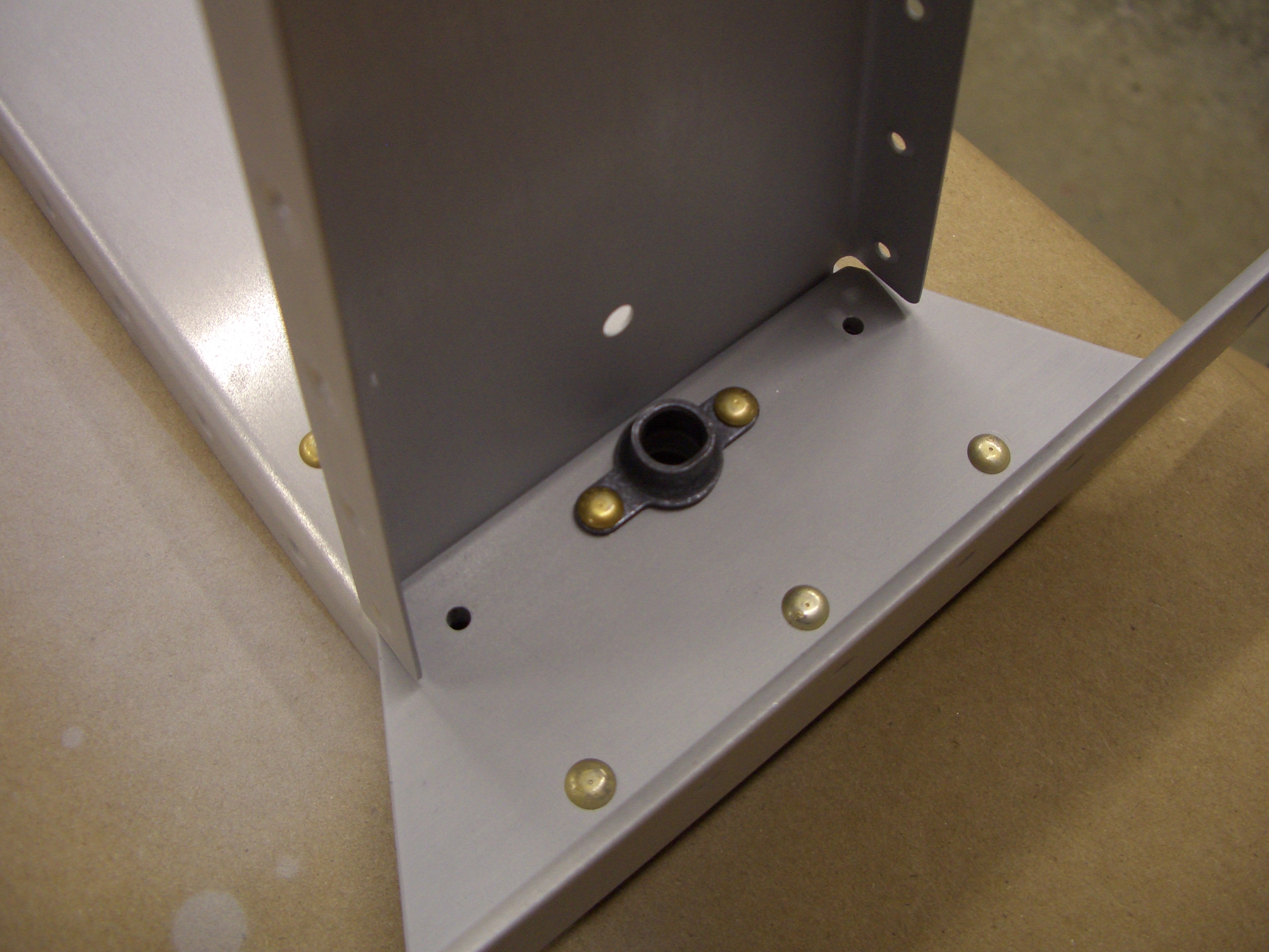
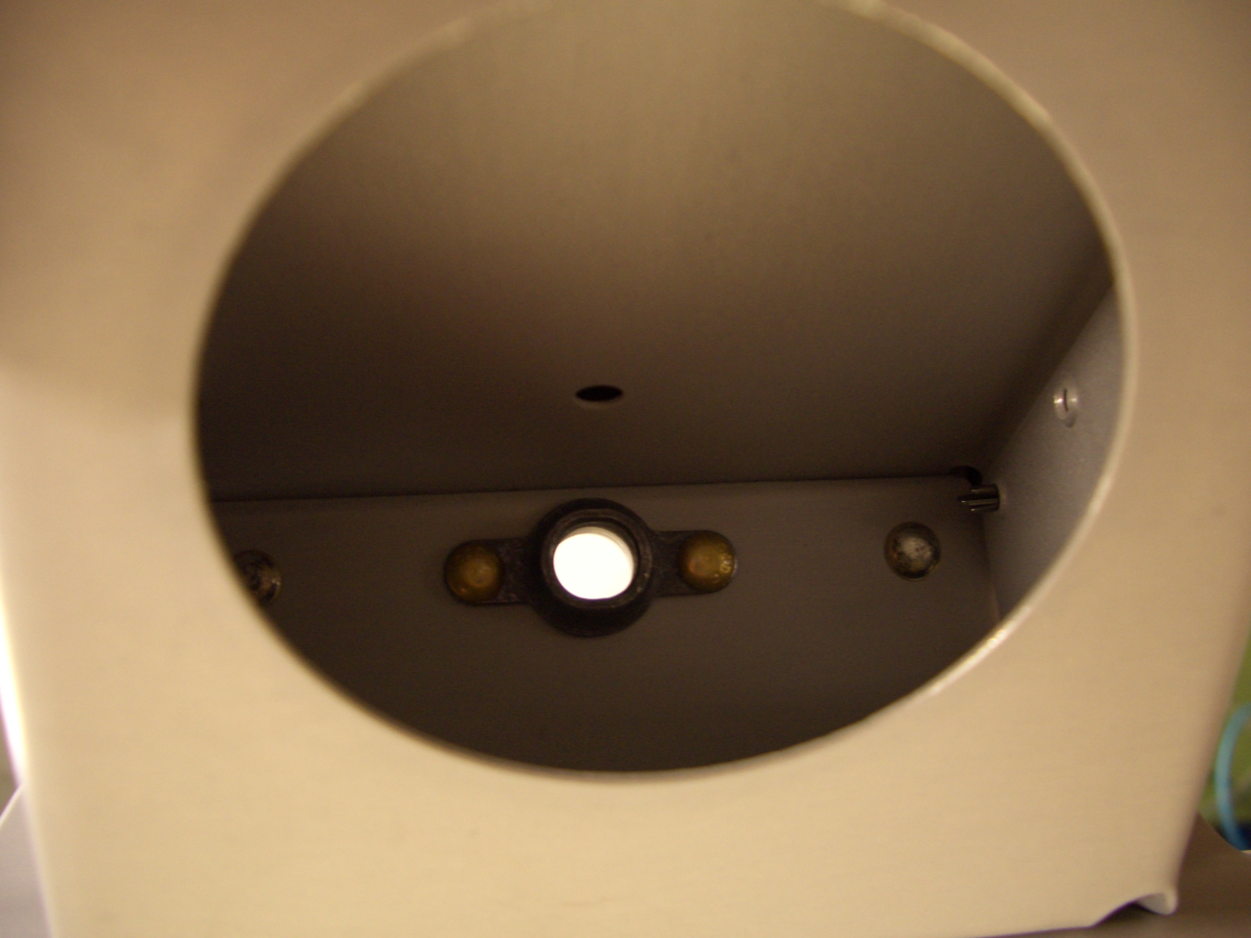
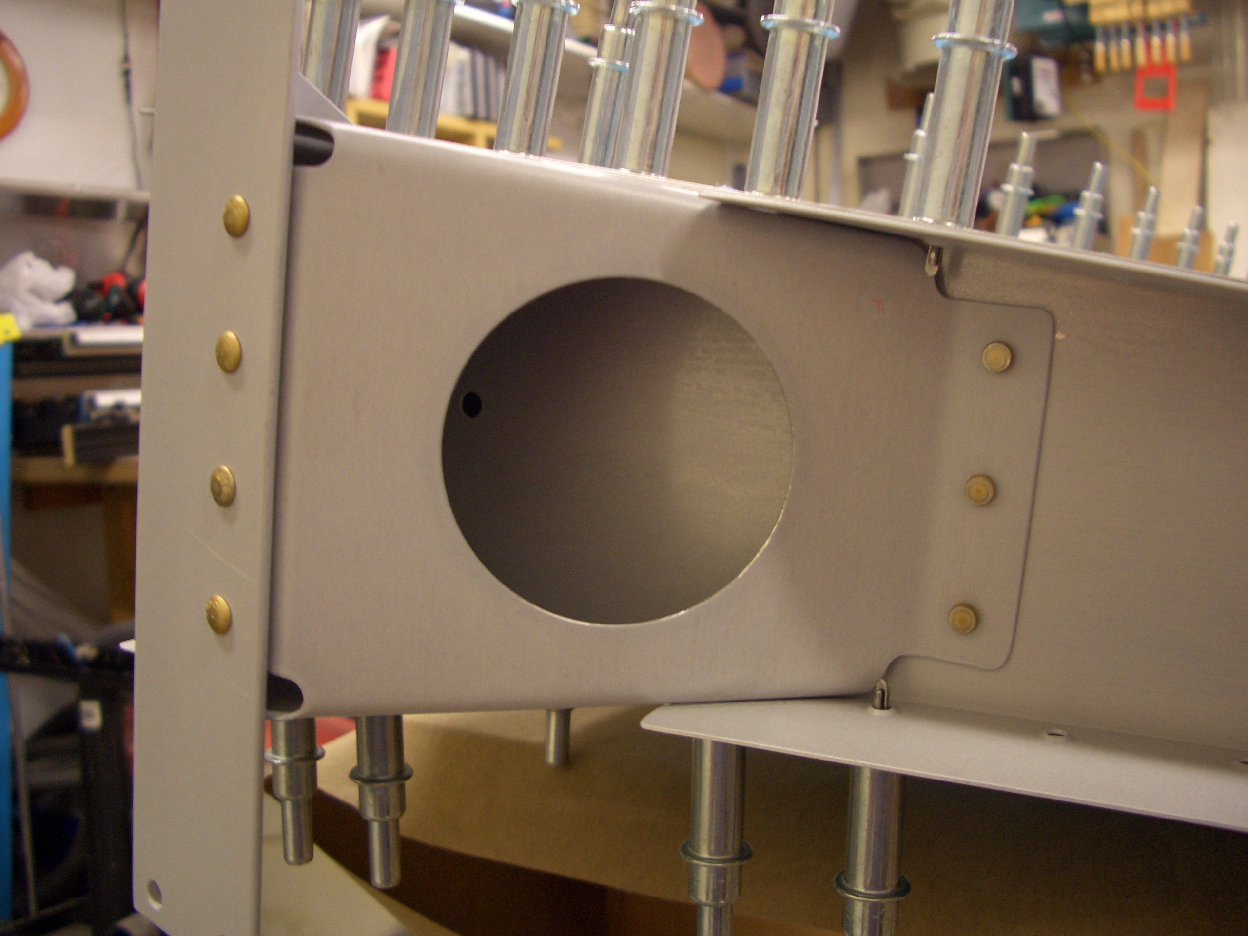
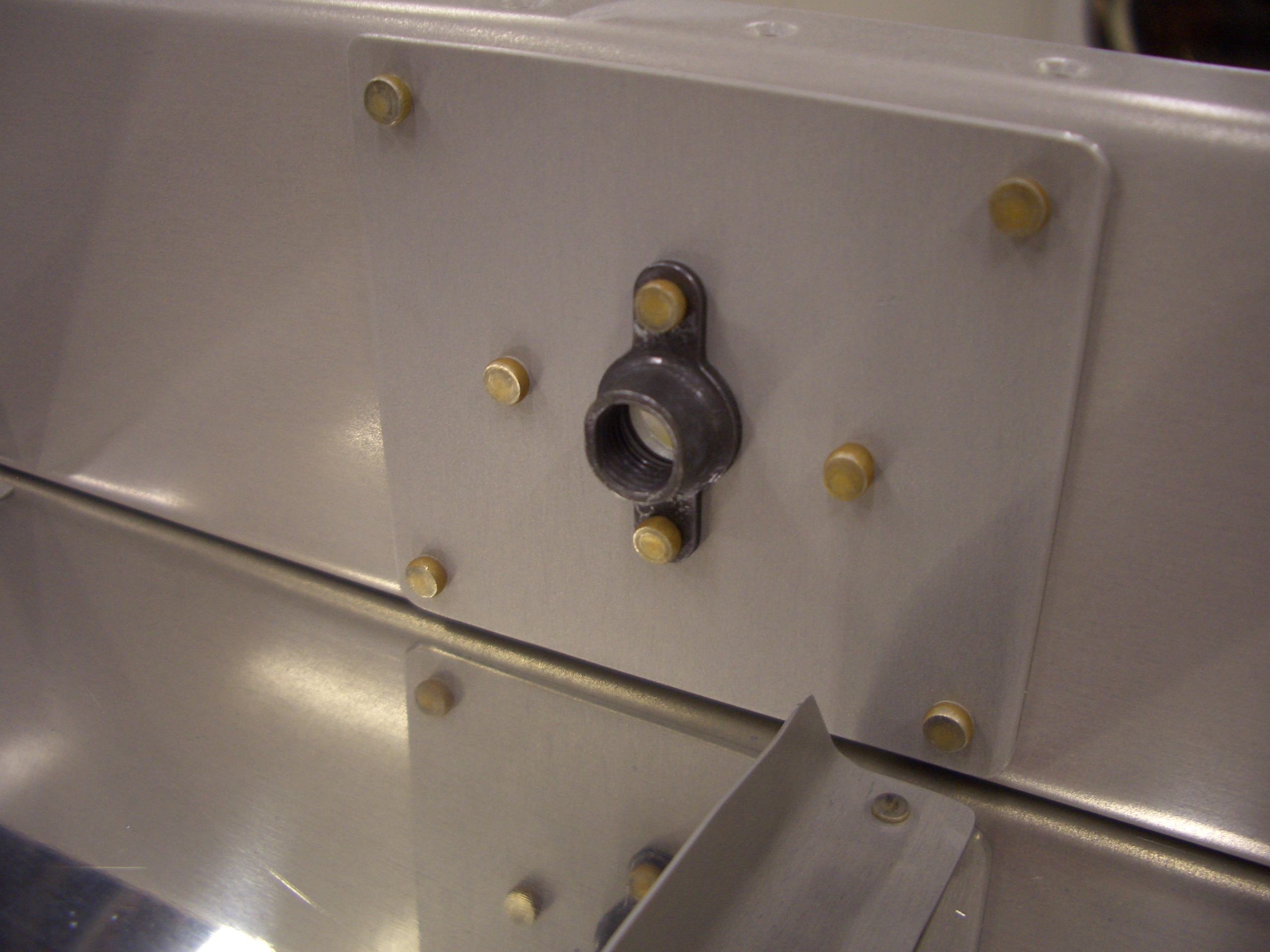
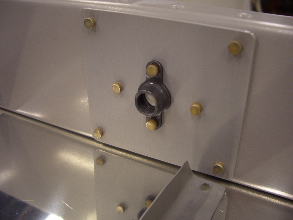
Here are a couple of pictures of the back of the rudder hinge reinforcement plates, mostly for the DAR to see that these are set correctly since there is no way to see inside the rudder once the skins are riveted on.  Here’s the middle hinge reinforcement plate.


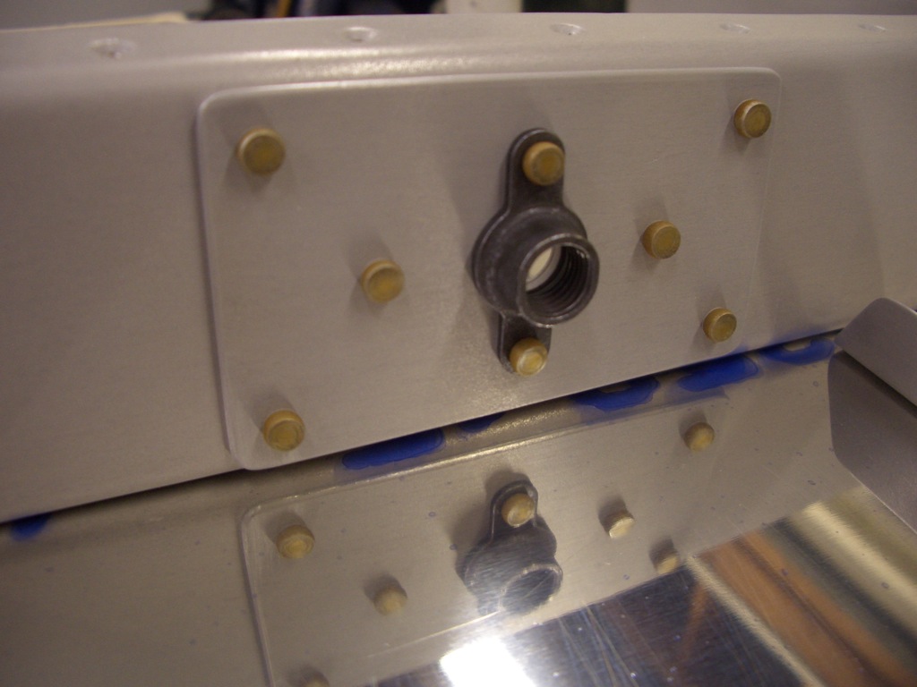
And here’s the upper hinge reinforcement plate.


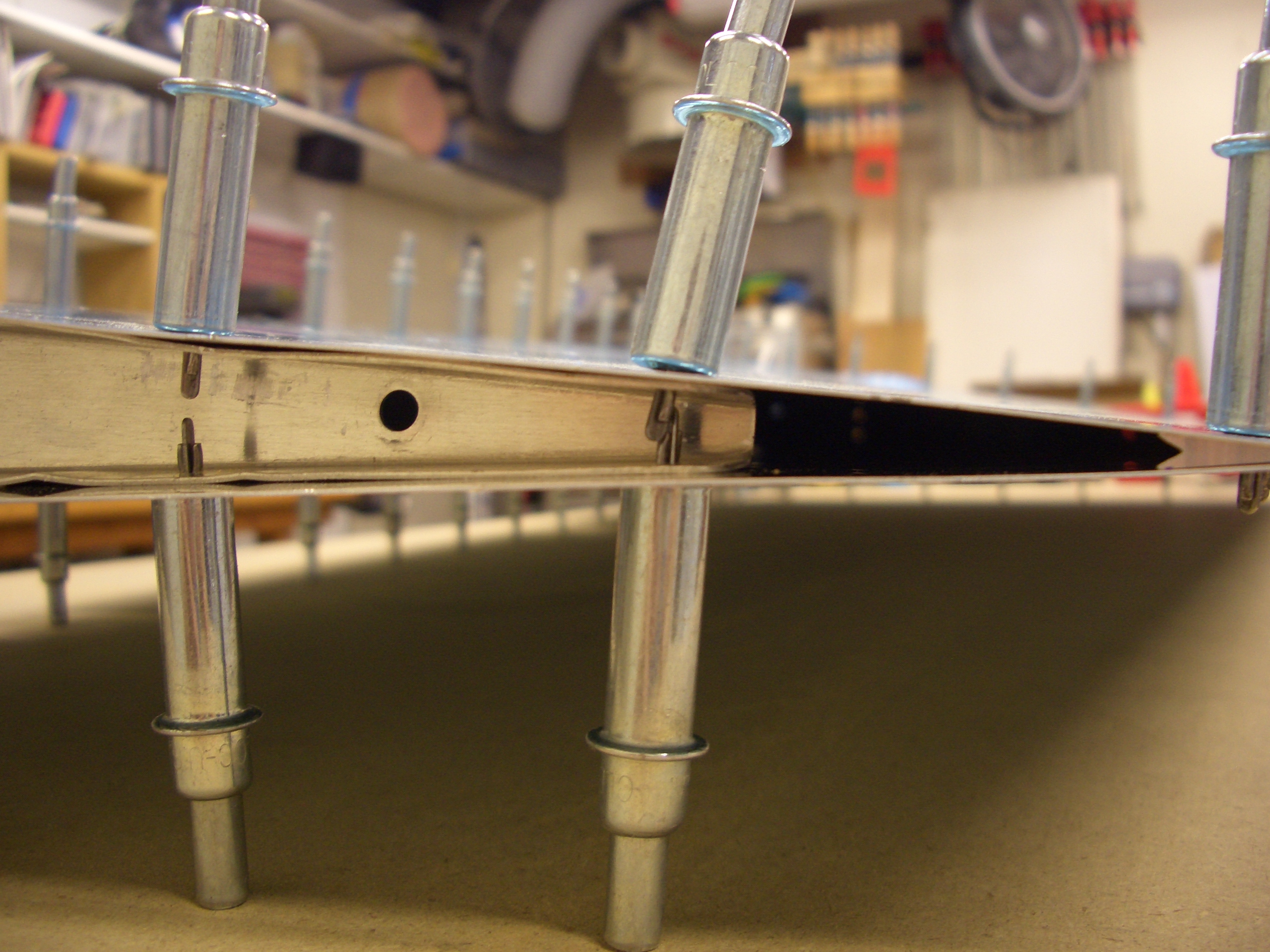
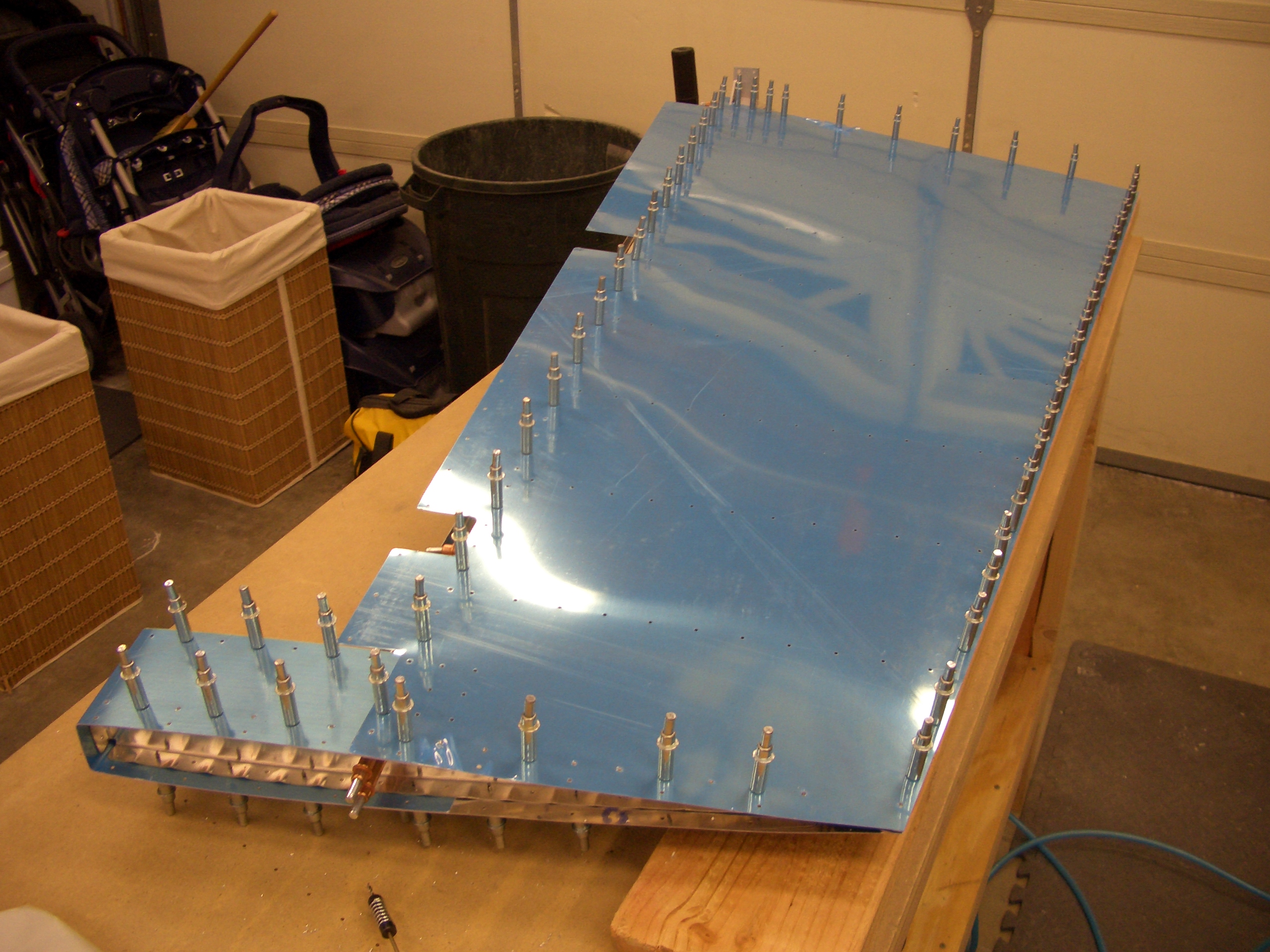
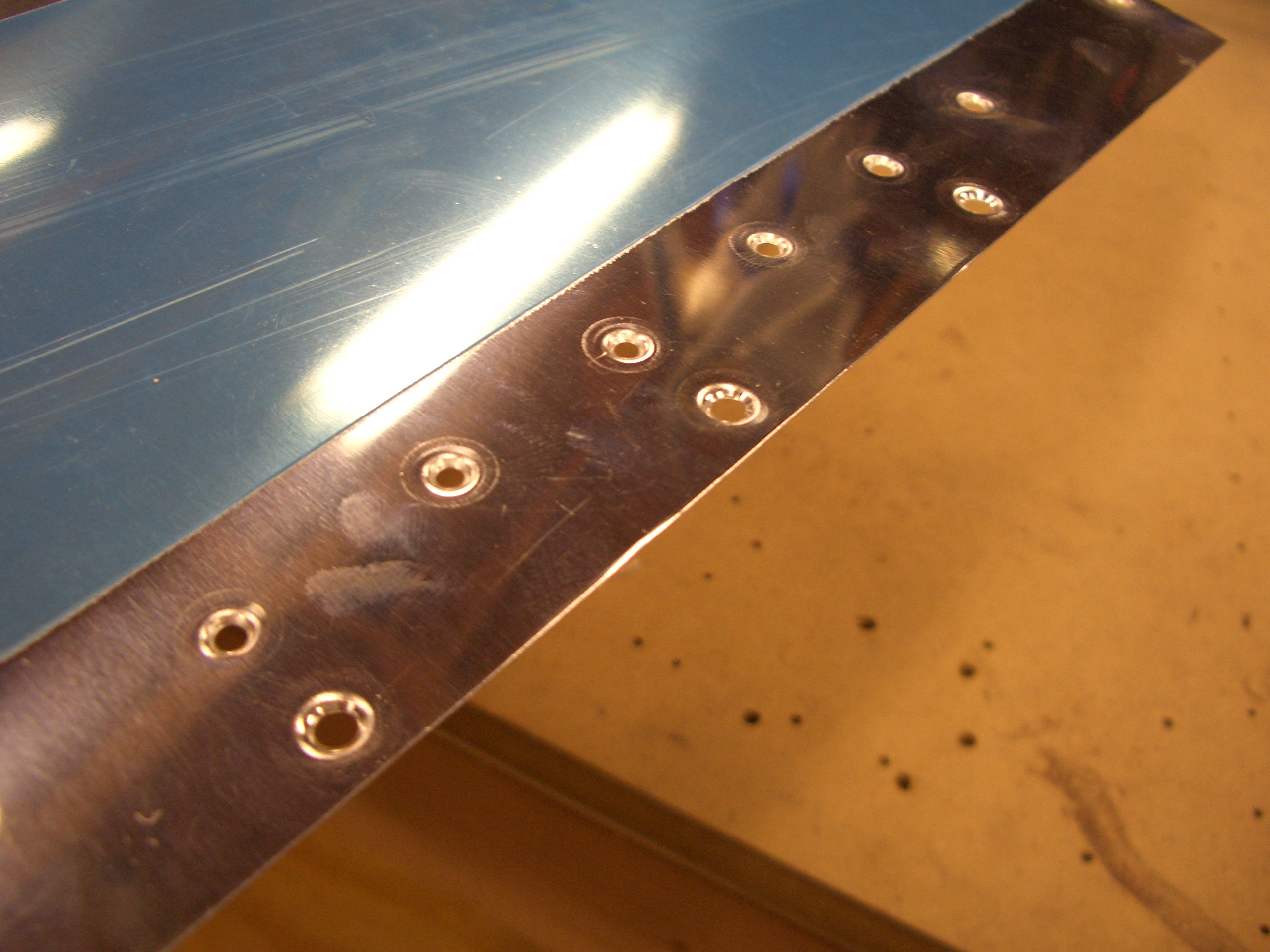
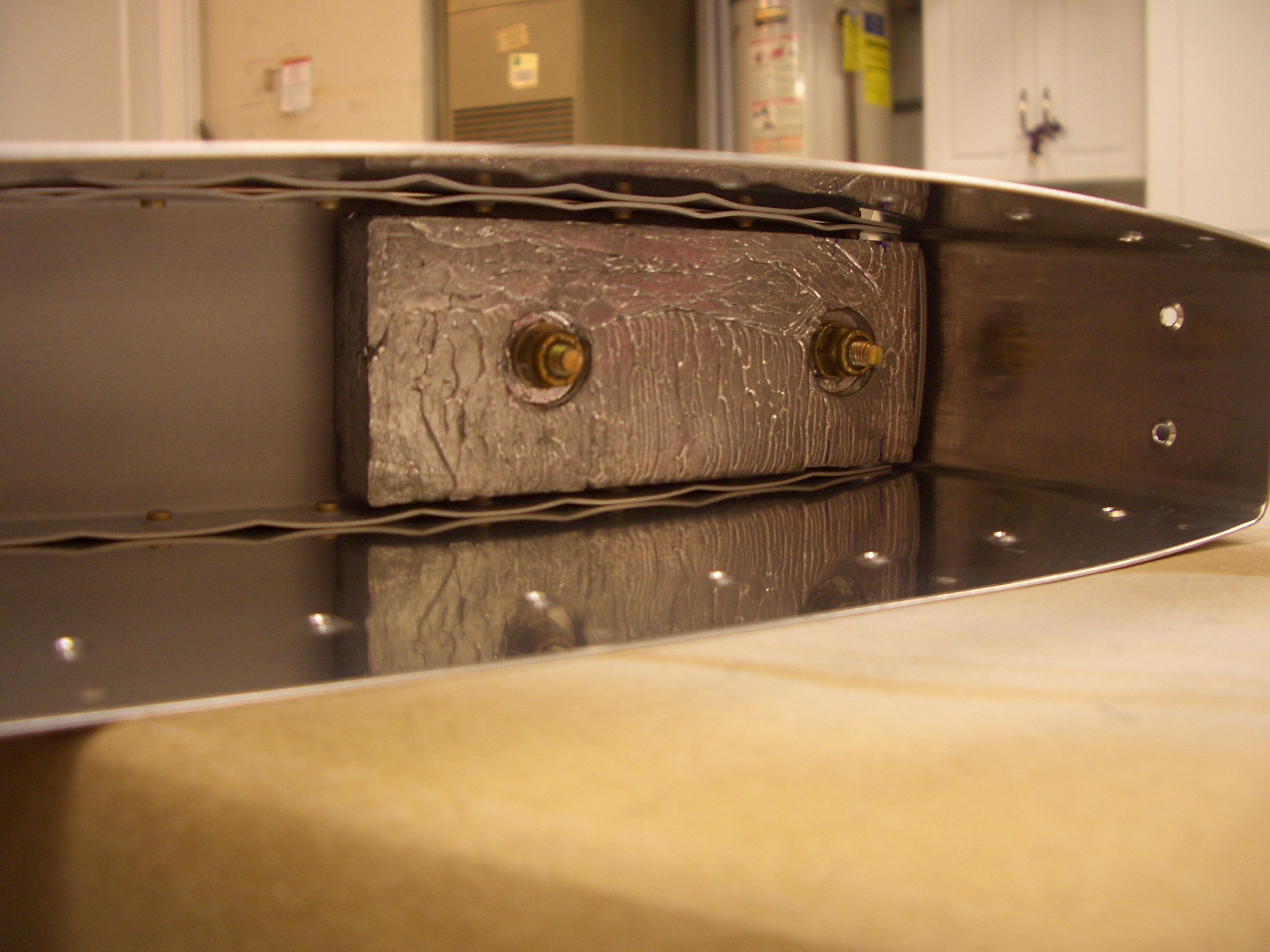
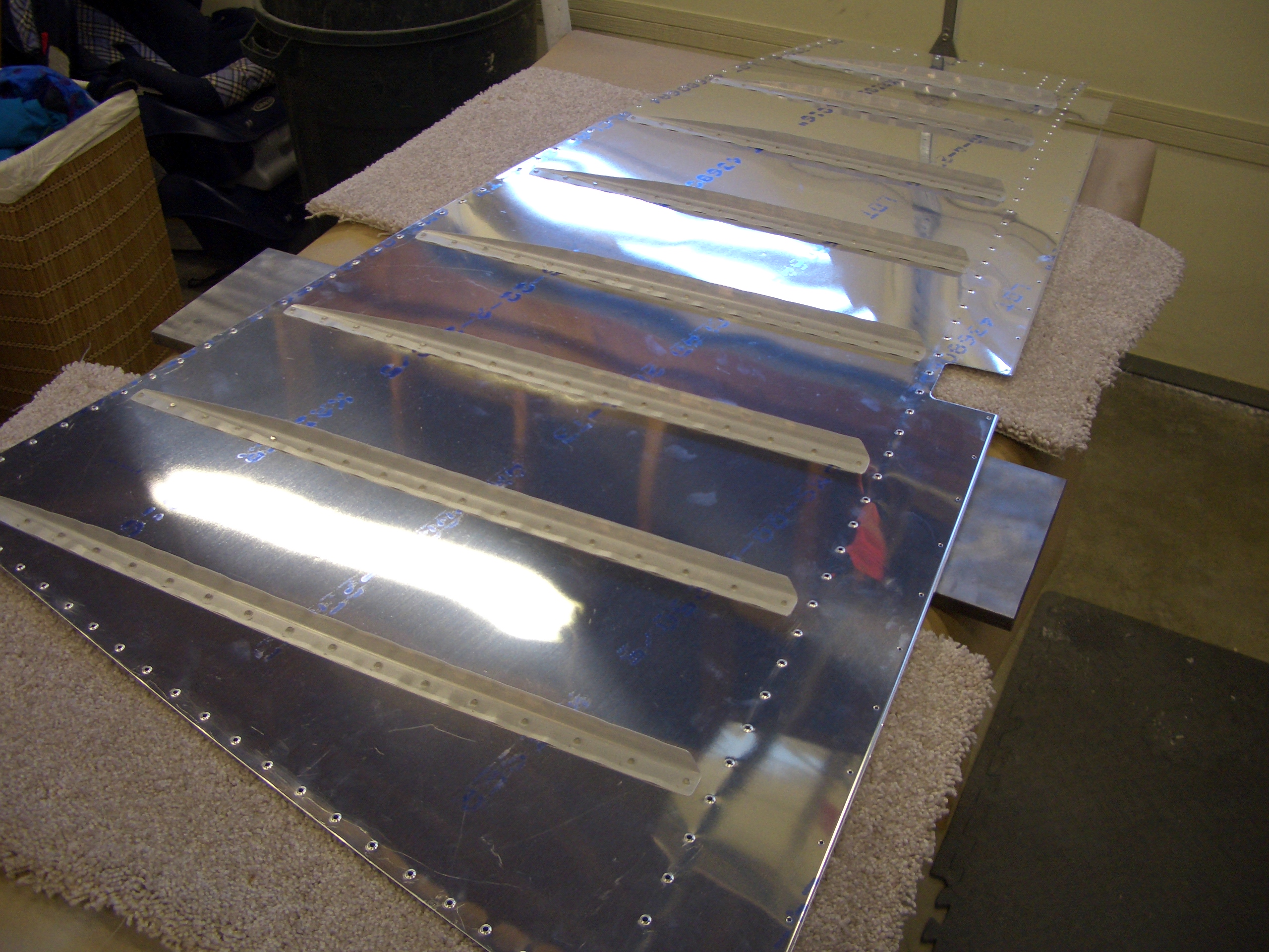
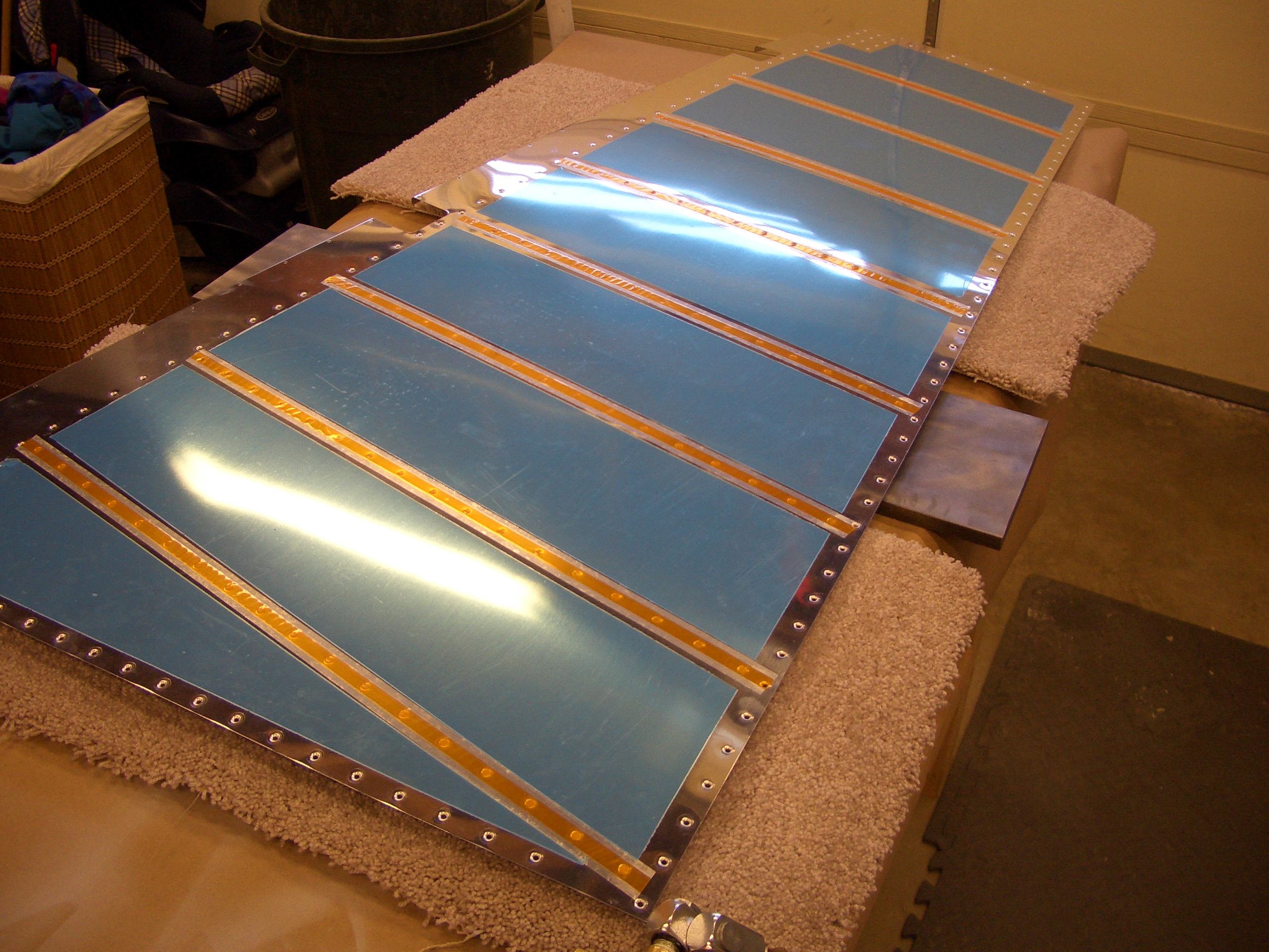
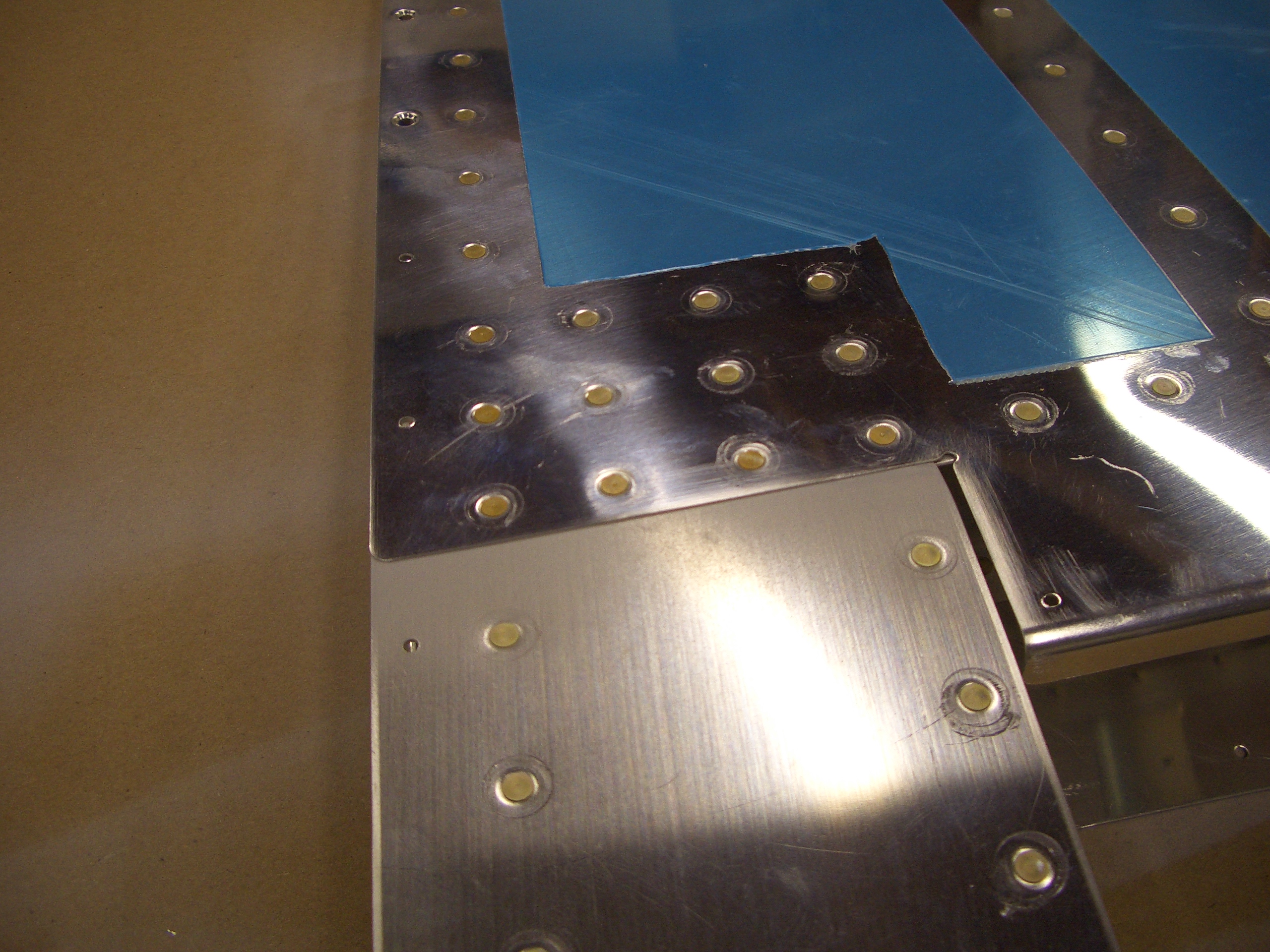
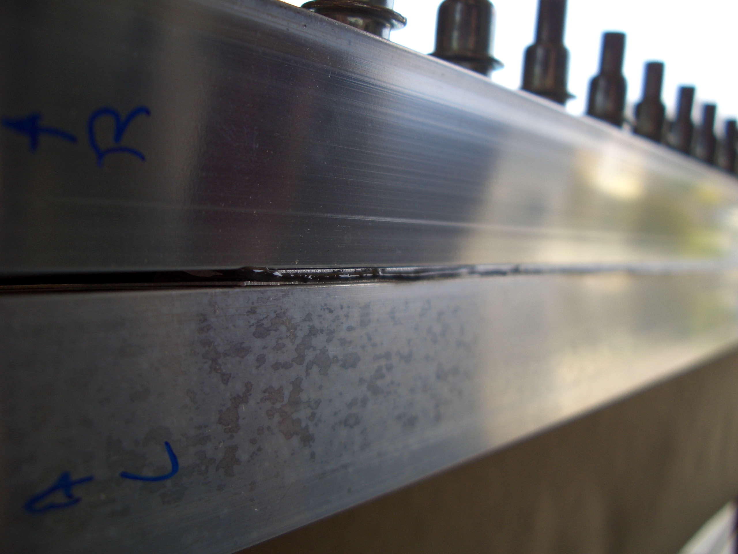
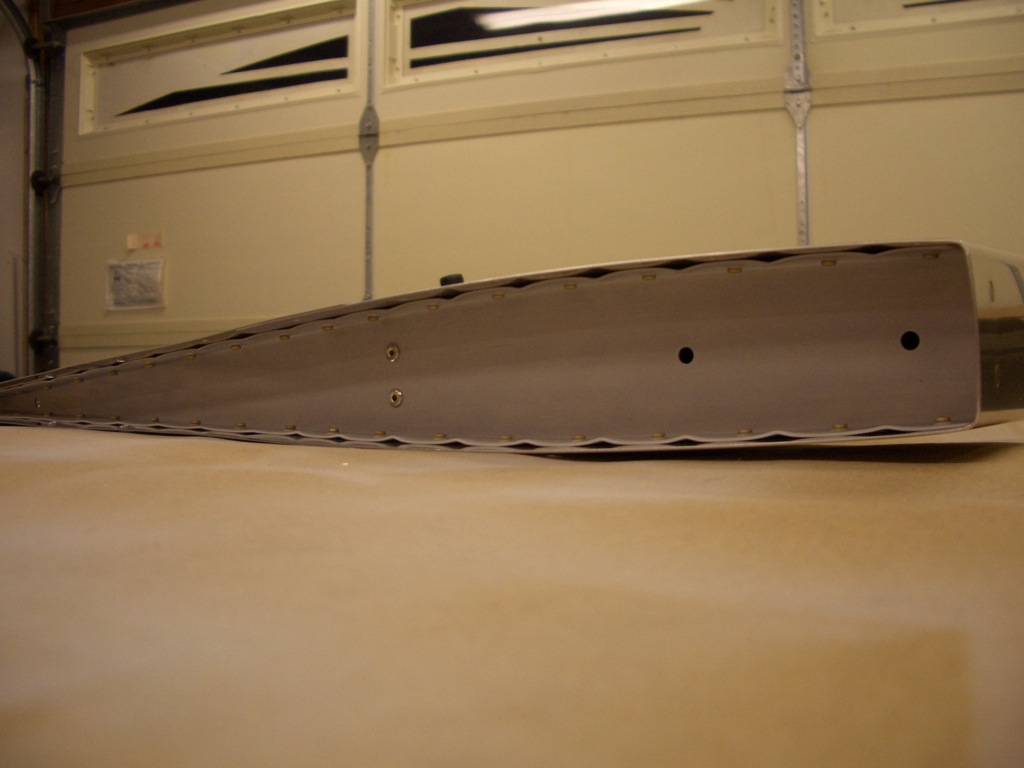
I got both skins fully riveted on (except for the trailing edge).  Here are the counterbalance skin to main skin rivets.  You can sorta see here how the tapering I did on the counterbalance skin allows the main skin to flow smoothly down on to the spar.  When you feel it, you can barely detect the joint.  This will all get covered in filler most likely when I do the fiberglass work for the rudder top fairing.


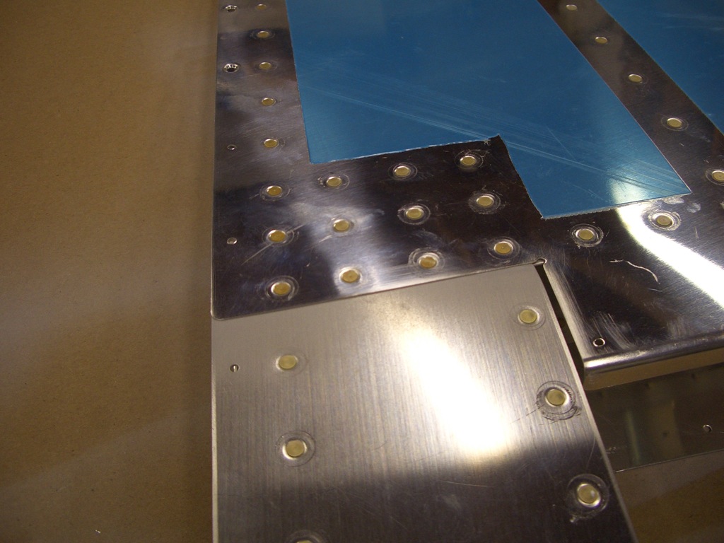
Here’s the top rib riveted on.  The top rib is riveted to the spar with pop rivets since the other side of this joint is inaccessible (or nearly so).  The only thing to remember here is to switch from AN426AD3-3.5 to AN426AD3-4 rivets where the skins overlap since there’s a little more material the rivet is going through.


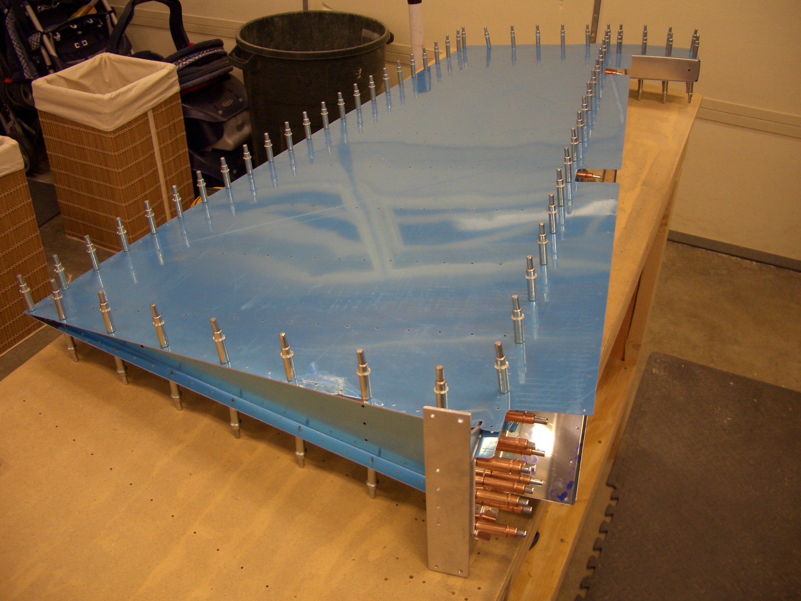
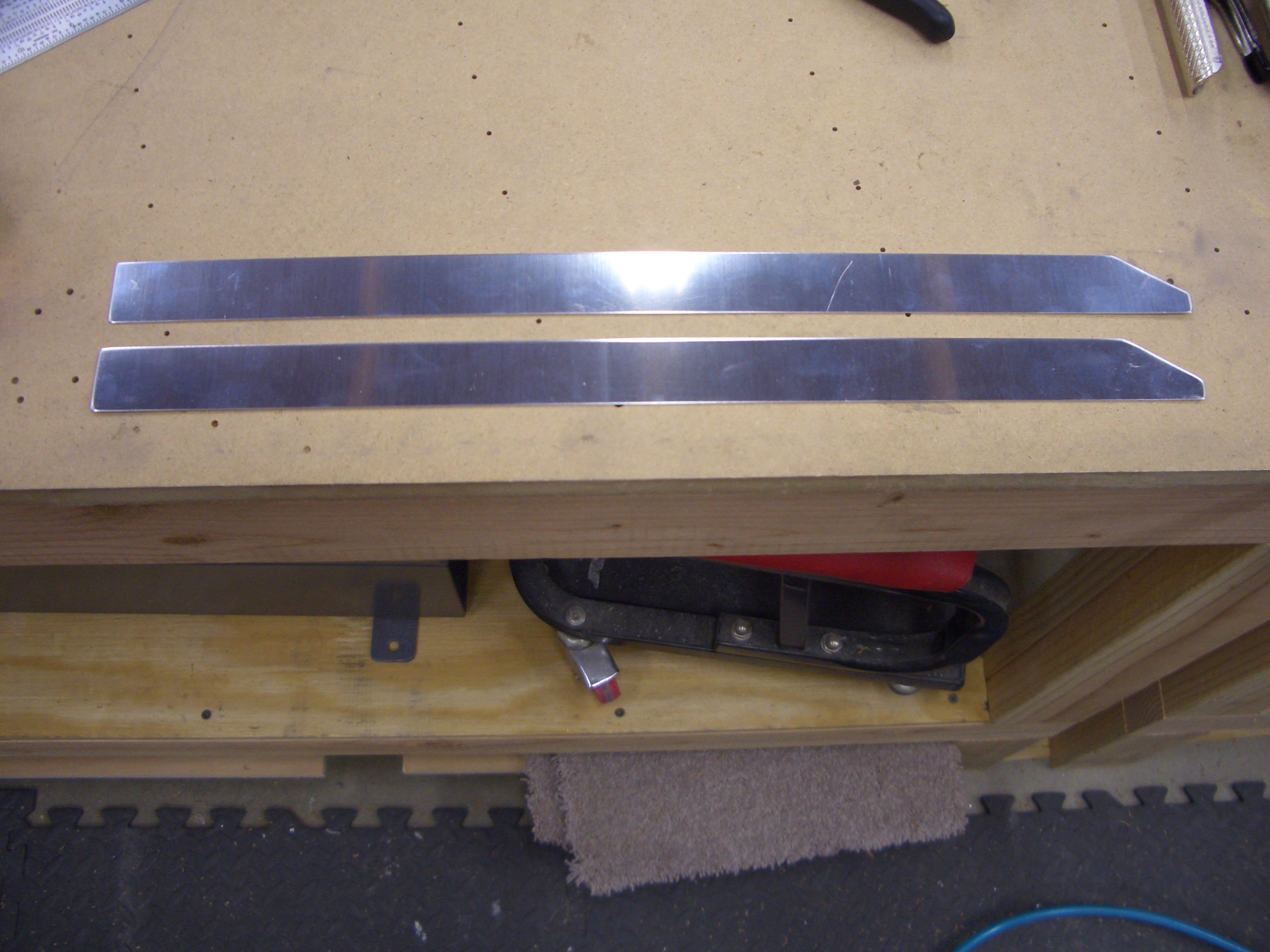
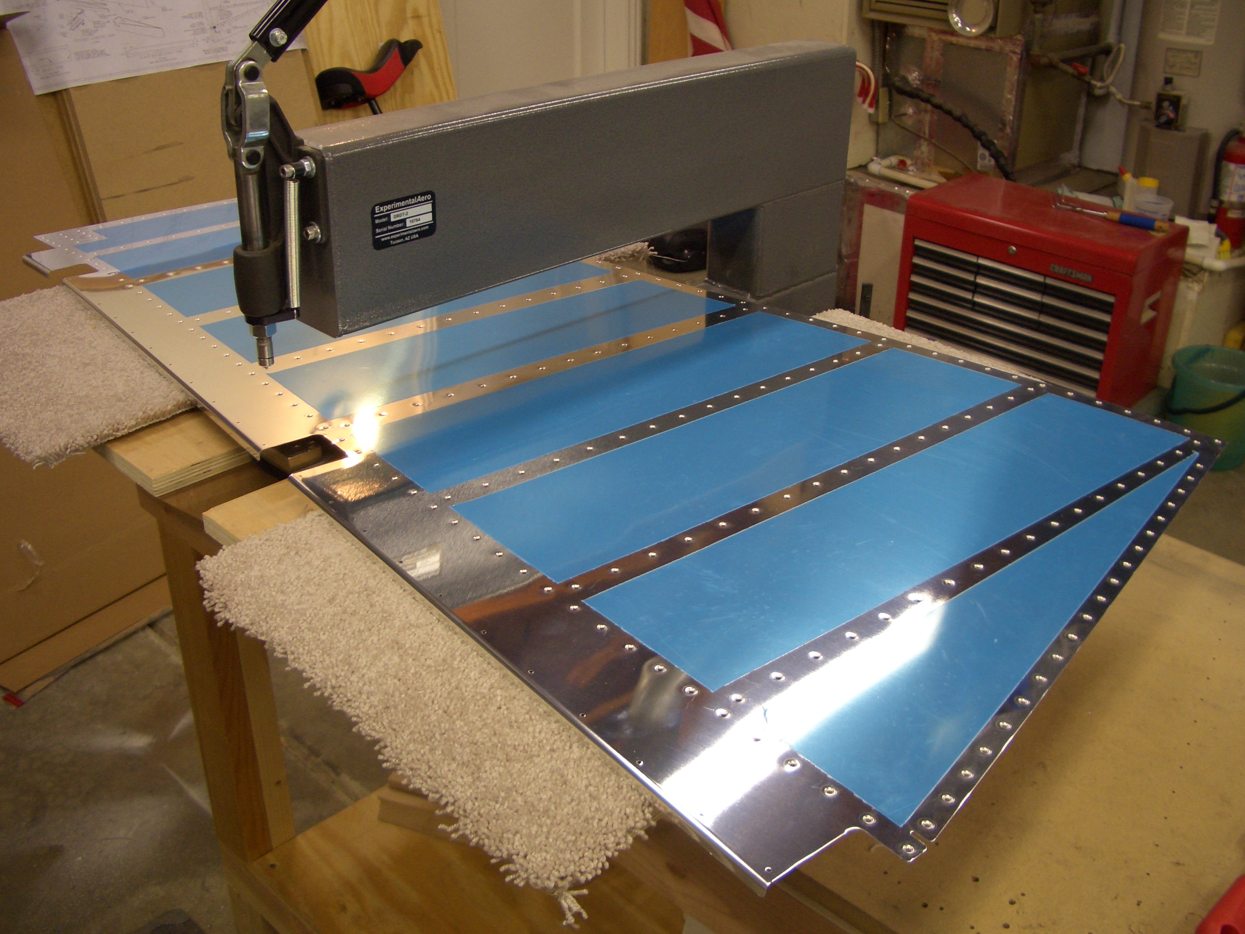
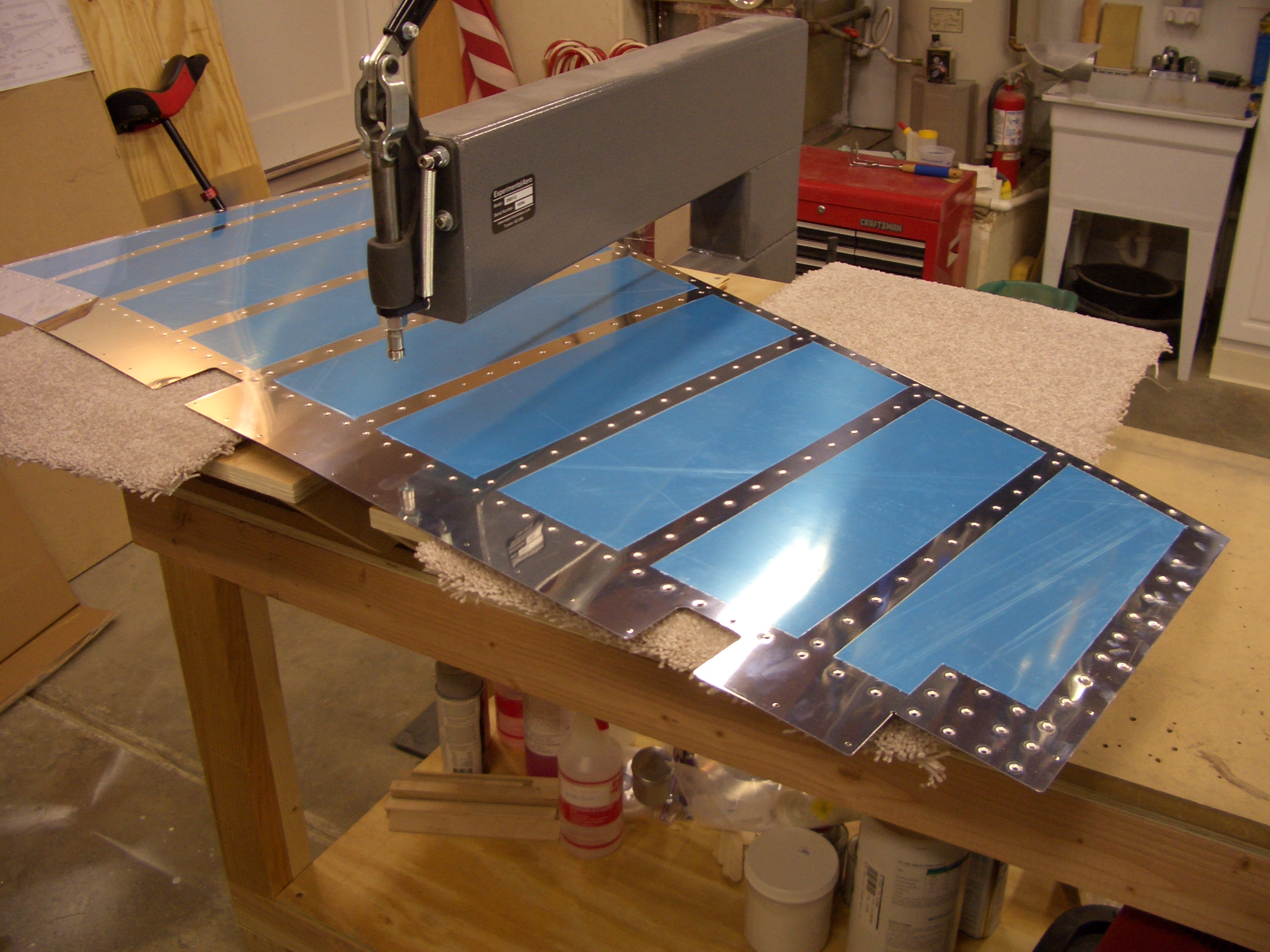
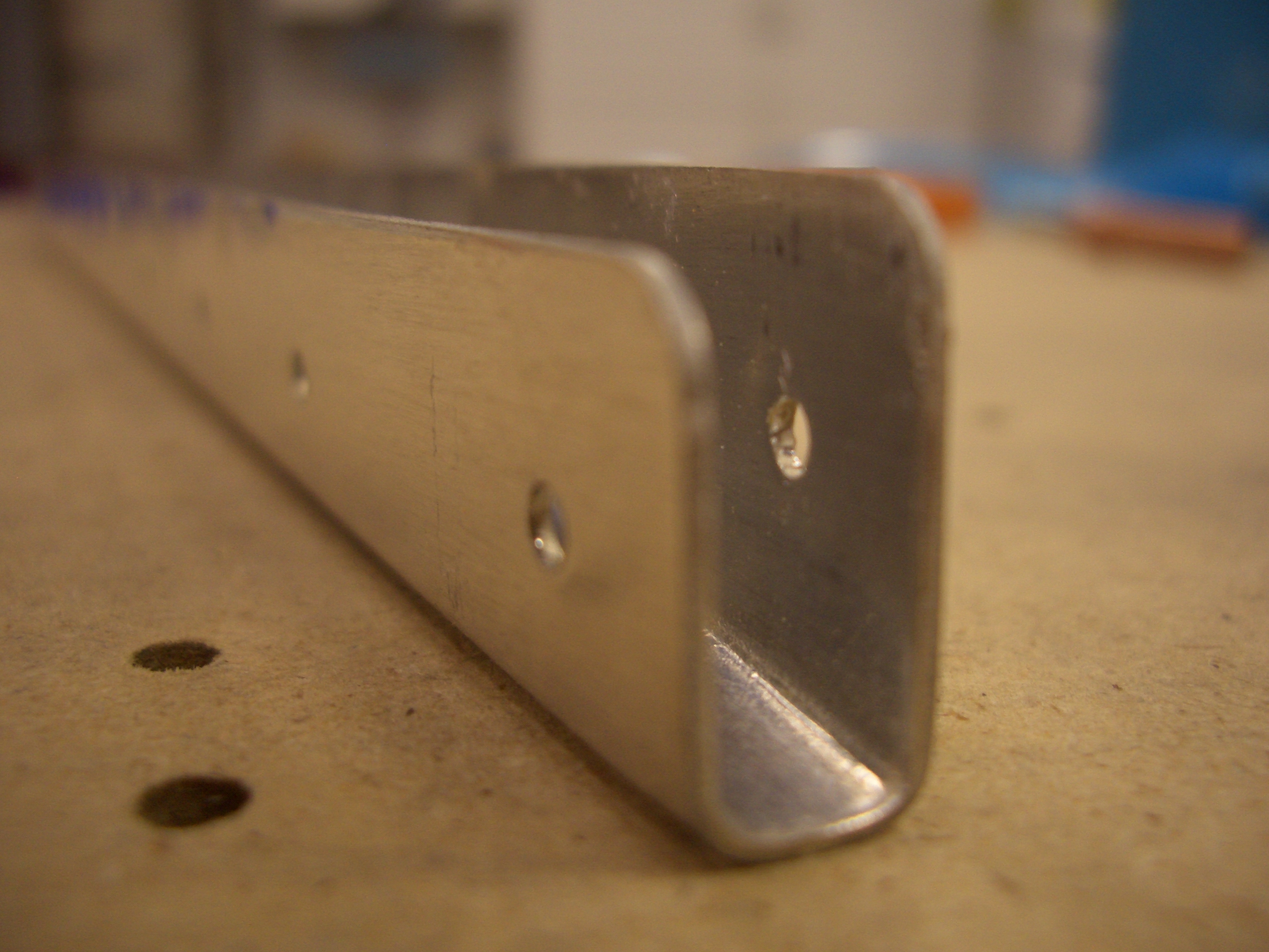
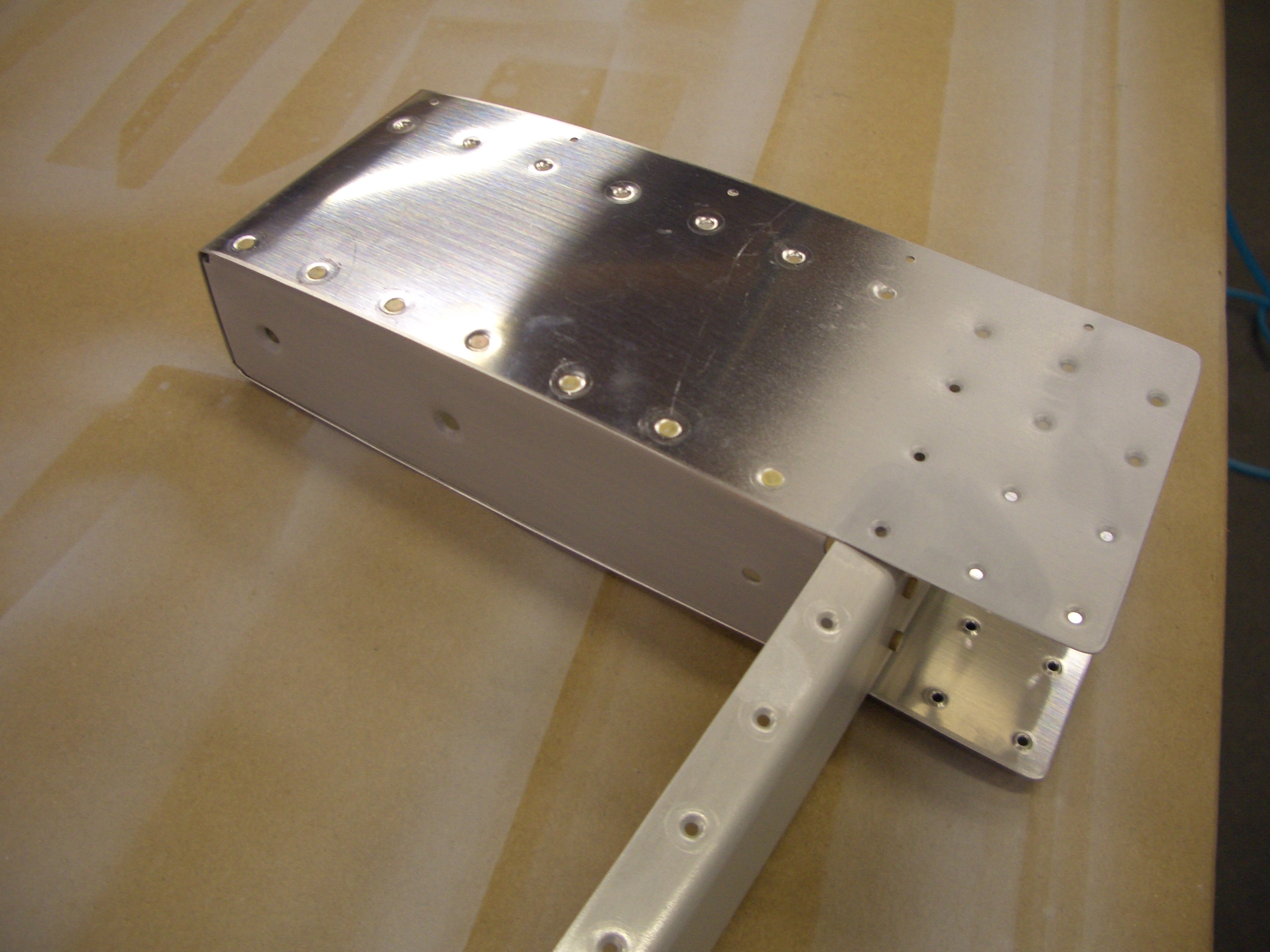
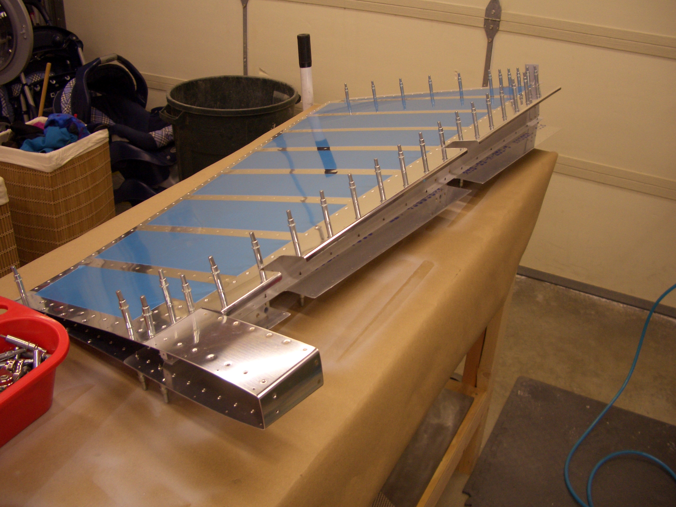
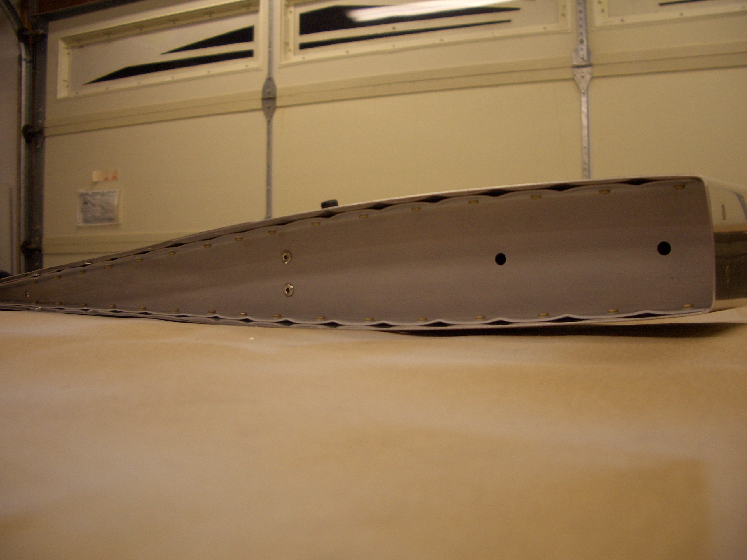
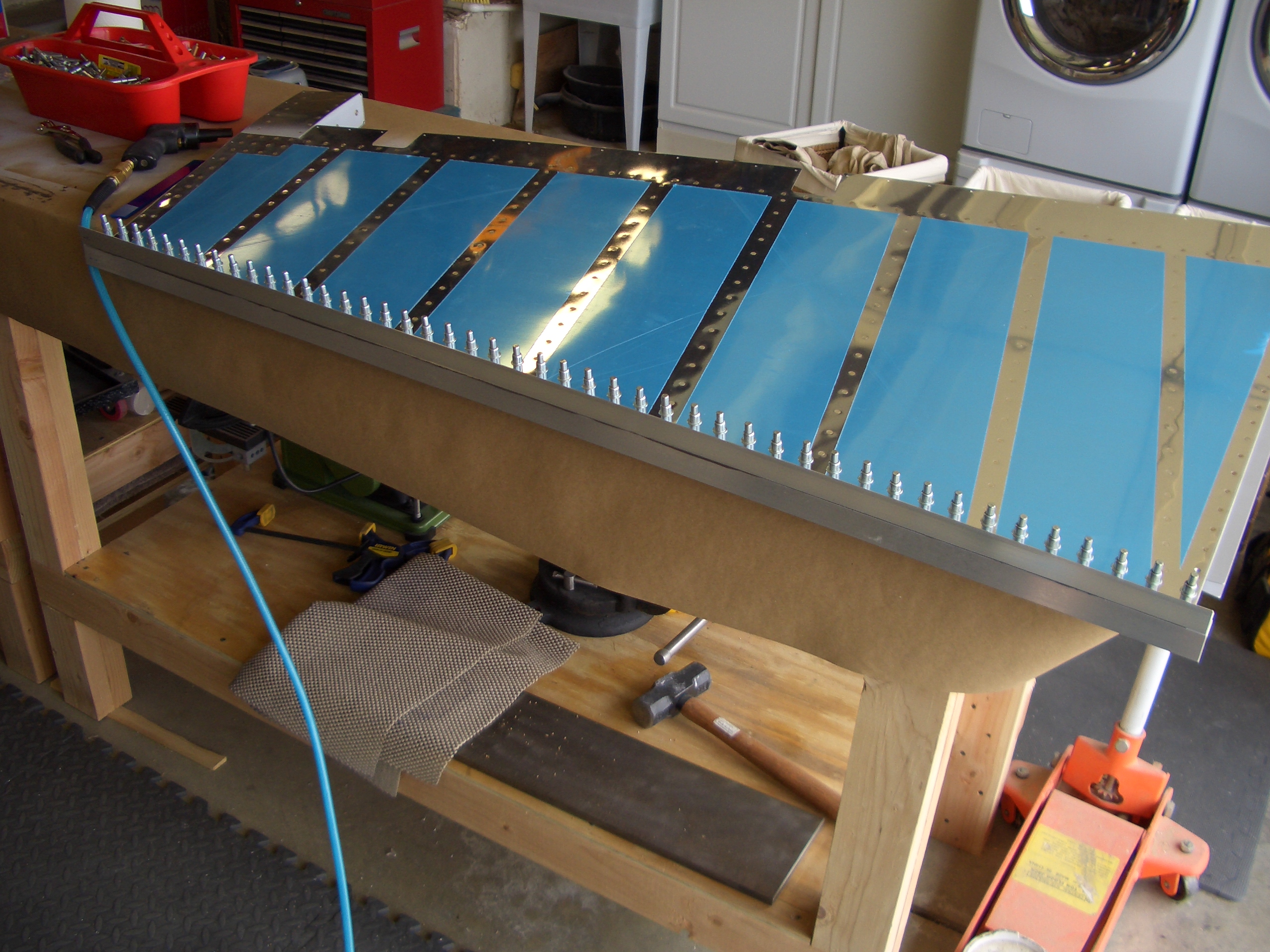
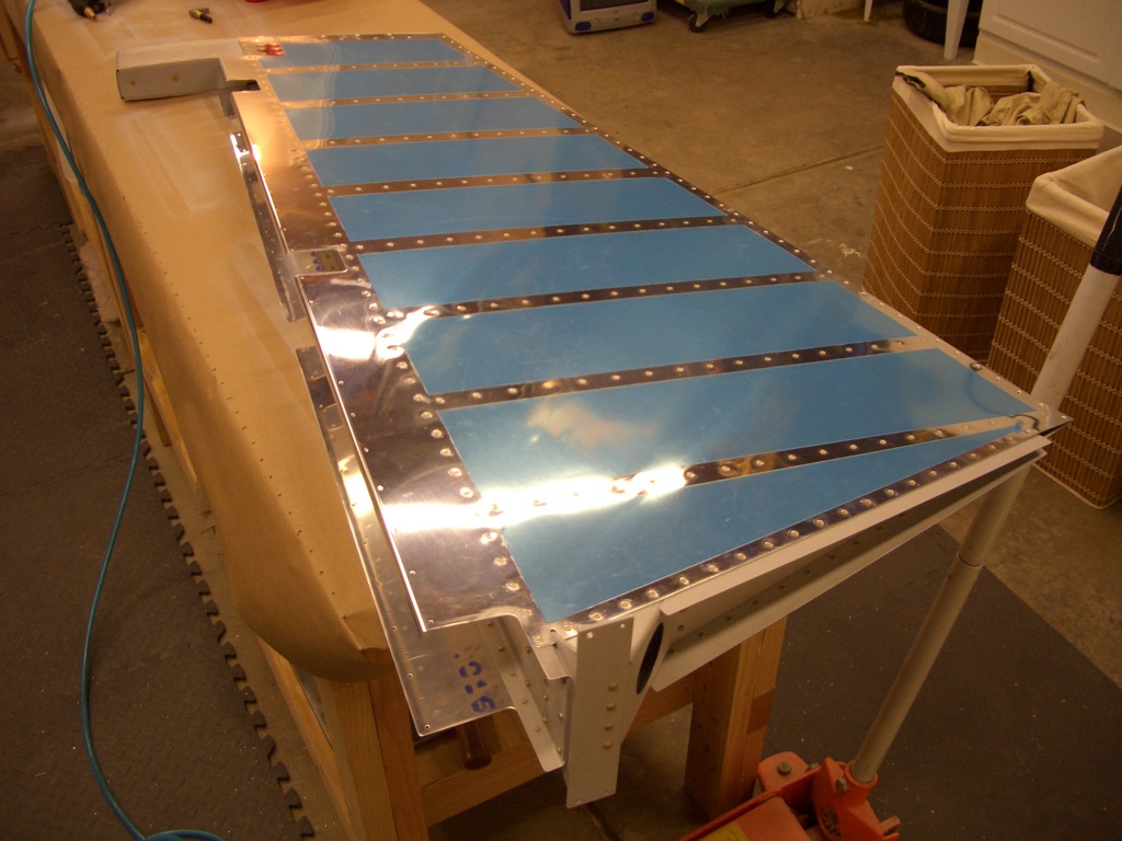
Here’s the completed rudder structure (again excluding the trailing edge.  I’ve already drilled two aluminum angles that I picked up at Home Depot, so all I need to do is clean this, apply the sealant and cleco it together.


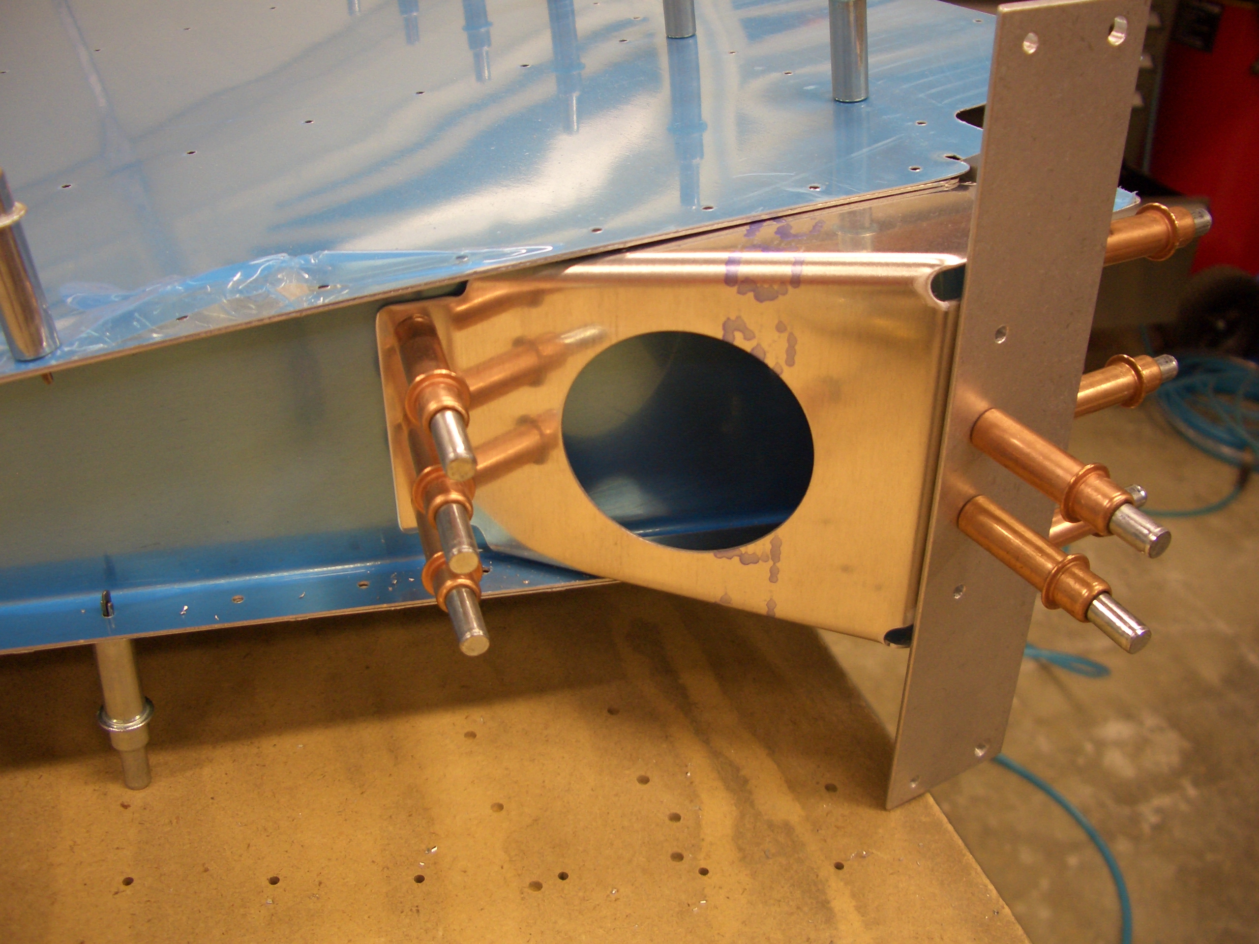
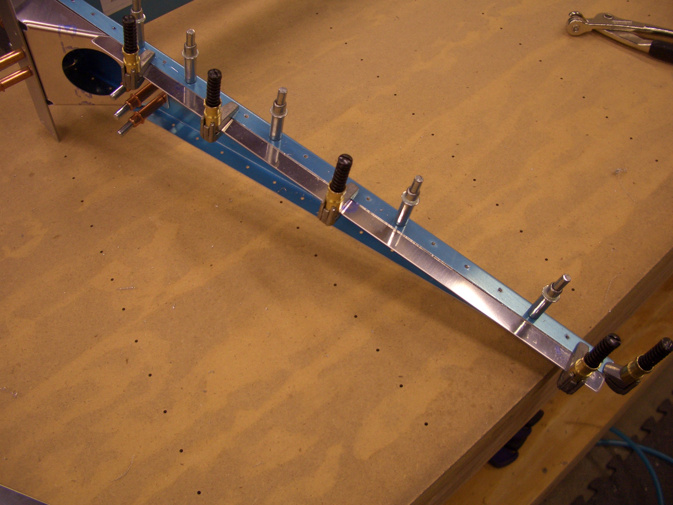
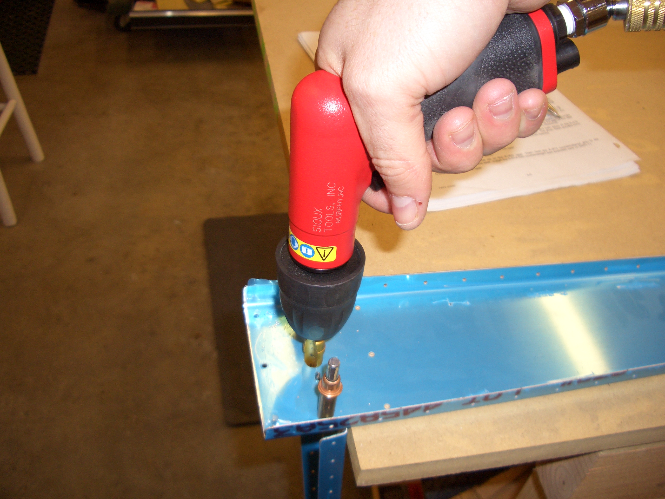
I managed to get all solid rivets where the skins and bottom rib join the horn brace.  The longeron yoke got the rear three, but the hinge nutplate interfered with the yoke when I tried to do the front rivet.  The three-inch yoke with a 1/2″ flush set cleared fine.  I hand squeezed all of these so that I could easily back off if I felt interference.  The pneumatic squeezer has so much power that it would easily bend any interfering parts before you could stop it.

Applied Sealant to Rudder Trailing Edge

I didn’t get any pictures of the actual process since the sealant is sticky as hell.  Literally, everything that it touches will stick and you can’t get it off without a fairly aggressive solvent like MEK.  Anyway, I used one of the tubes of sealant available from Van’s that is ready to be mixed.  It was kind of a waste since you only use maybe an ounce on the trailing edge wedge.  After mixing it, I used the Semco sealant gun I picked up on eBay to put a thin bead down both sides of the wedge then spread it smooth with a popsicle stick.  It was then just a matter of clecoing on the angles that I already made.  I put clecos every hole to provide even clamping pressure (you can see just a bit of sealant oozing out of a couple of spots along the edge).

Here’s a closeup showing the sealant that has squeezed out.  Now I just have to let this sit for 2-3 days to firm up and I can rivet the trailing edge.