Replaced Fuel Flow Sensor

My fuel flow has been erratic again recently. This has happened a number of times and Electronics International has always indicated that the cause is almost always the electrical connections. I’ve tried crimp connectors, solder, solder sleeves, and finally their own OLC-1 and now OLC-2 connectors. Interestingly, the problem would always appear to be resolved for a bit, but would then reappear some number of hours later.

A friend mentioned that he’d had a similar experience and a replacement fuel flow sensor fixed it. Out of other options to try, I ordered one and installed it tonight.

Their new OLC-2 connectors have two crimp screws per connector so you don’t have to try to hold both wires in place simultaneously while trying to tighten the screws. I don’t like how these connectors provide no strain relief for the wires, so I did my best to immobilize everything.

I leak tested everything and ground-ran the engine. Initial run showed nice, solid fuel flows.

Swapped Propellers

The RV-7 was designed before the days of composite constant-speed propellers, and was further designed for the 200hp, angle-valve IO-360 motor. Taking Van’s advice to build the lightest plane possible, I opted for the WhirlWind Aviation 200RV composite prop and the much lighter IO-375 motor. This meant I was approximately 70lbs lighter in the nose than the plane was designed for. This put my C.G. much farther aft than typical, and it was in fact easy to load the plane aft of the aft C.G. limit.

I spoke with Van for a bit at a party last year, and he indicated that the easiest change to make (short of just bolting on some weight) would be to switch to an aluminum constant speed propeller. When my 200RV prop started slinging grease back in the spring, it seemed like the perfect time to do the swap.

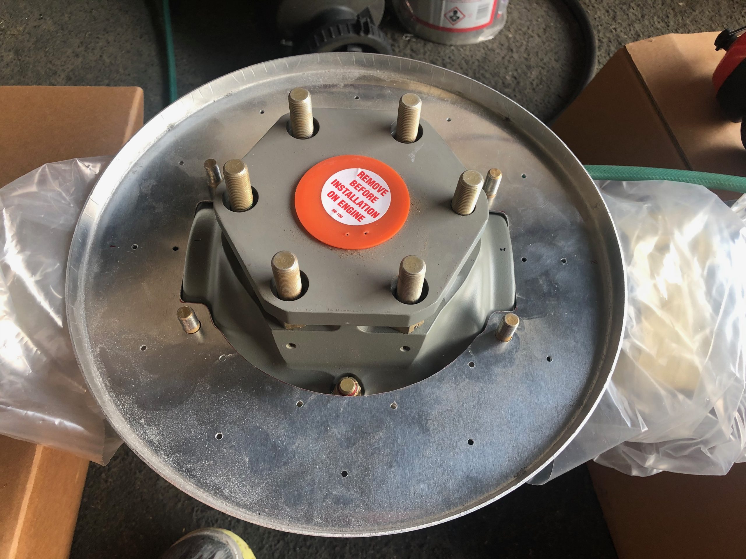
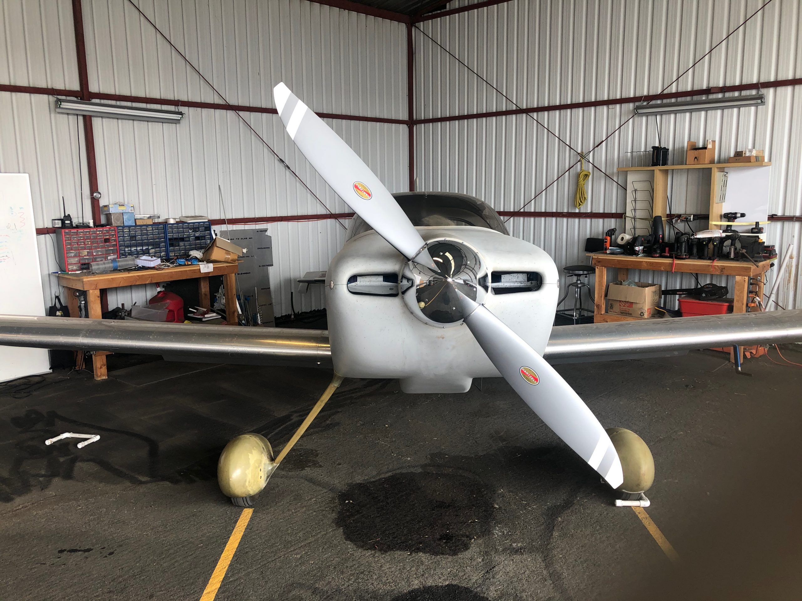
I ordered the Hartzell C2YR-1BFP/F7497 through Van’s. This is a 74″ prop and not normally recommended for the RV-7 due to being 2″ longer than the 72″, recommended prop. However, I spoke with someone at Hartzell, and he indicated that there were advantages in thrust with the 74″, and the extra weight only helped my situation. The only downside for me is reduced ground clearance. The 200RV had 8 3/8″ under normal gear compression in a level attitude, so this prop should have 1″ less, or 7 3/8″. In a hard landing, or if I inadvertently raised the tail too far, this would be reduced. However, I virtually always fly off hard surface runways and generally do tail-low wheel landings, so I’m not particularly worried about the reduced clearance.

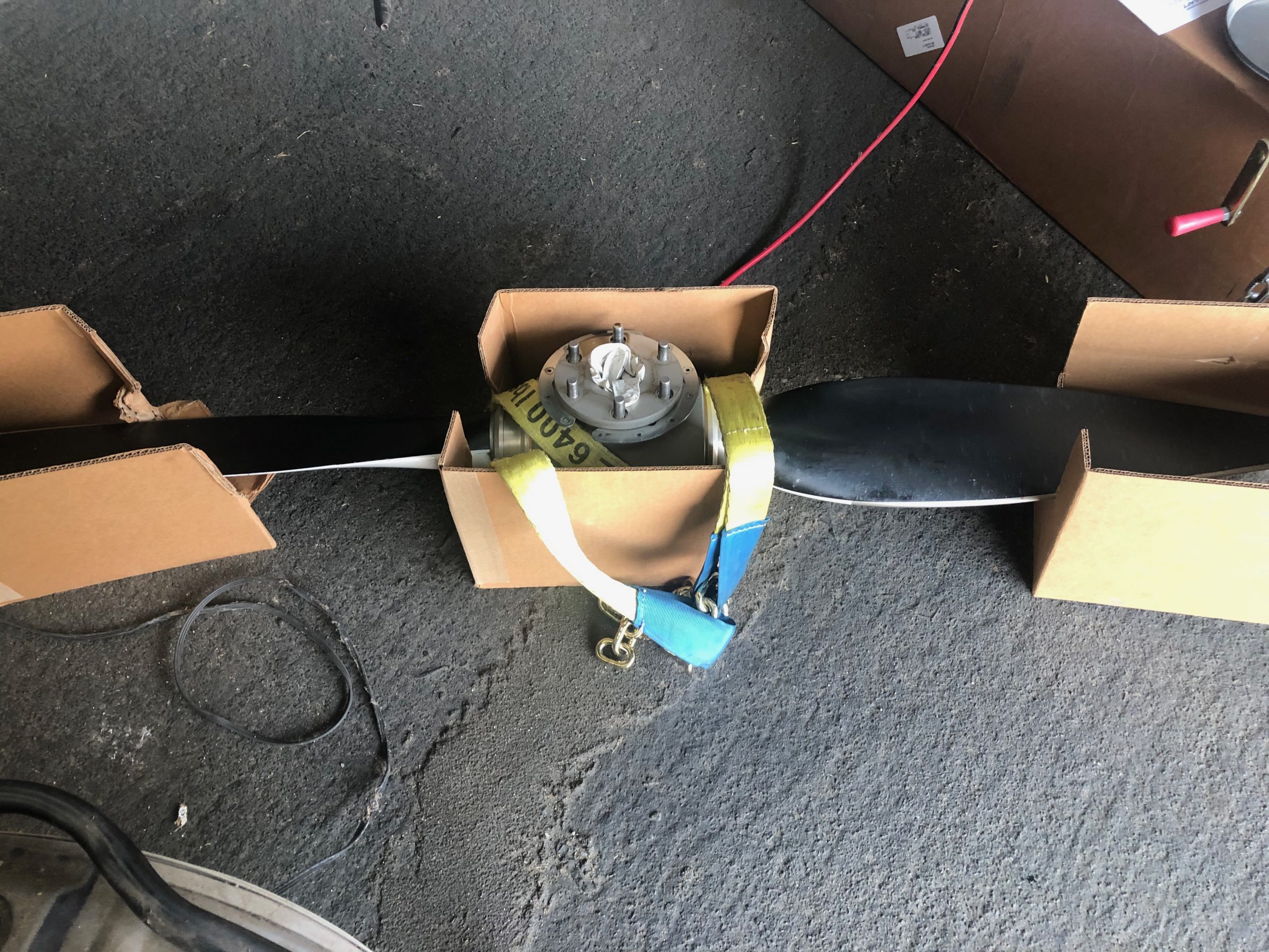
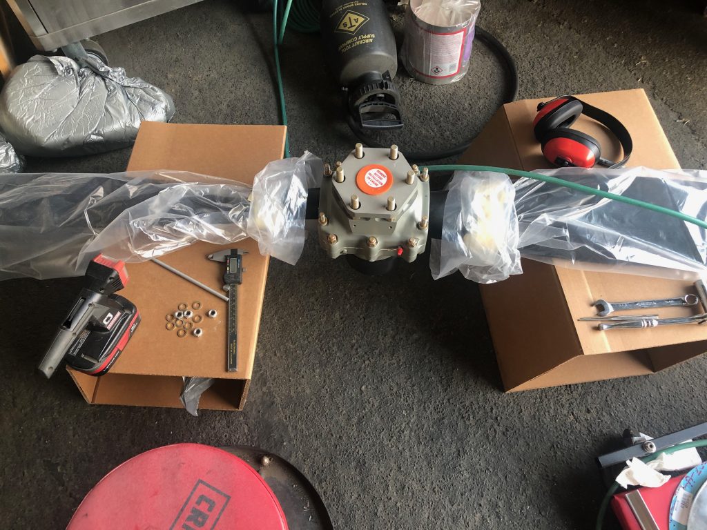
The prop shipped 4-6 weeks later and pretty quickly landed at the UPS hub in San Jose, CA where I live. Unfortunately, UPS then lost track of it for three weeks! Eventually, it turned up in a trailer full of packages that apparently sat unopened that whole time. I dropped by their hub and picked it up and brought it to the hangar where I opened it and got it ready to mount on the plane.

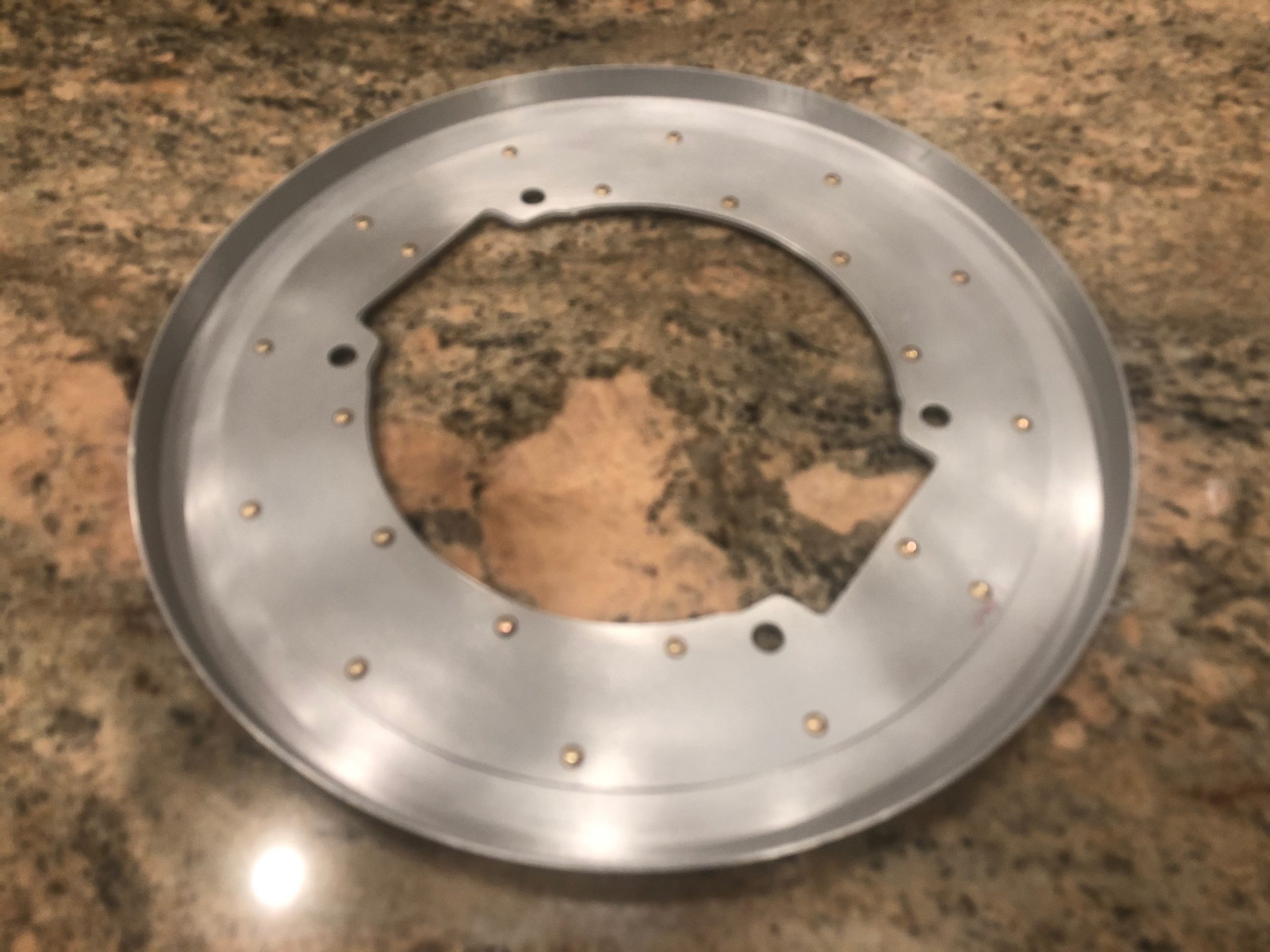
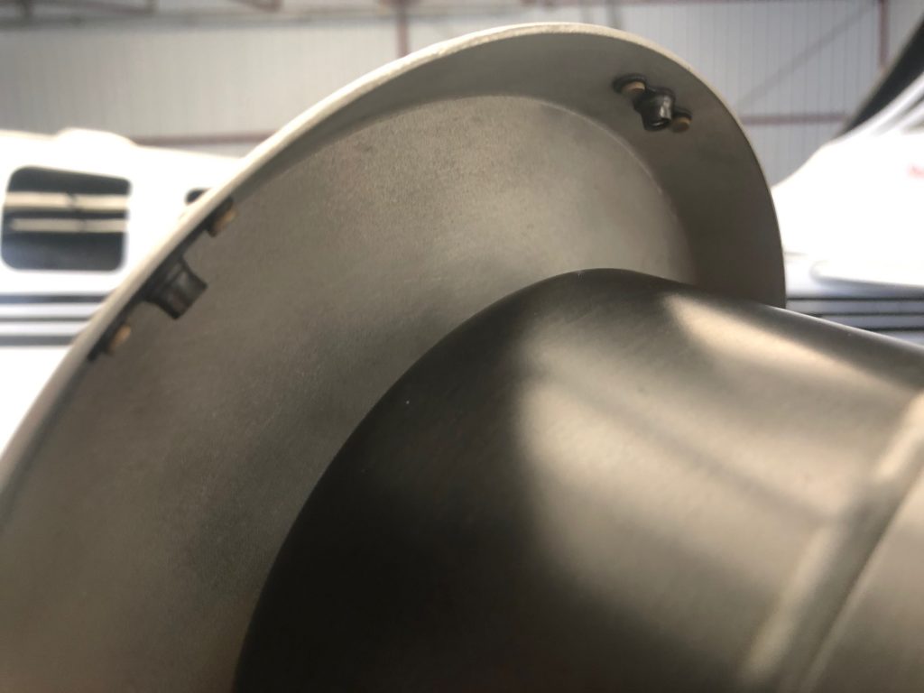
The first step is fitting the rear spinner bulkhead. This needs to be cut to match the doubler and then relieved further to fit on the propeller without touching the hub itself.

My buddy Michael was kind enough to let me drop by his place and shoot some of the Stewart Systems primer on the front and rear bulkheads, then I riveted the two parts of the rear bulkhead together.

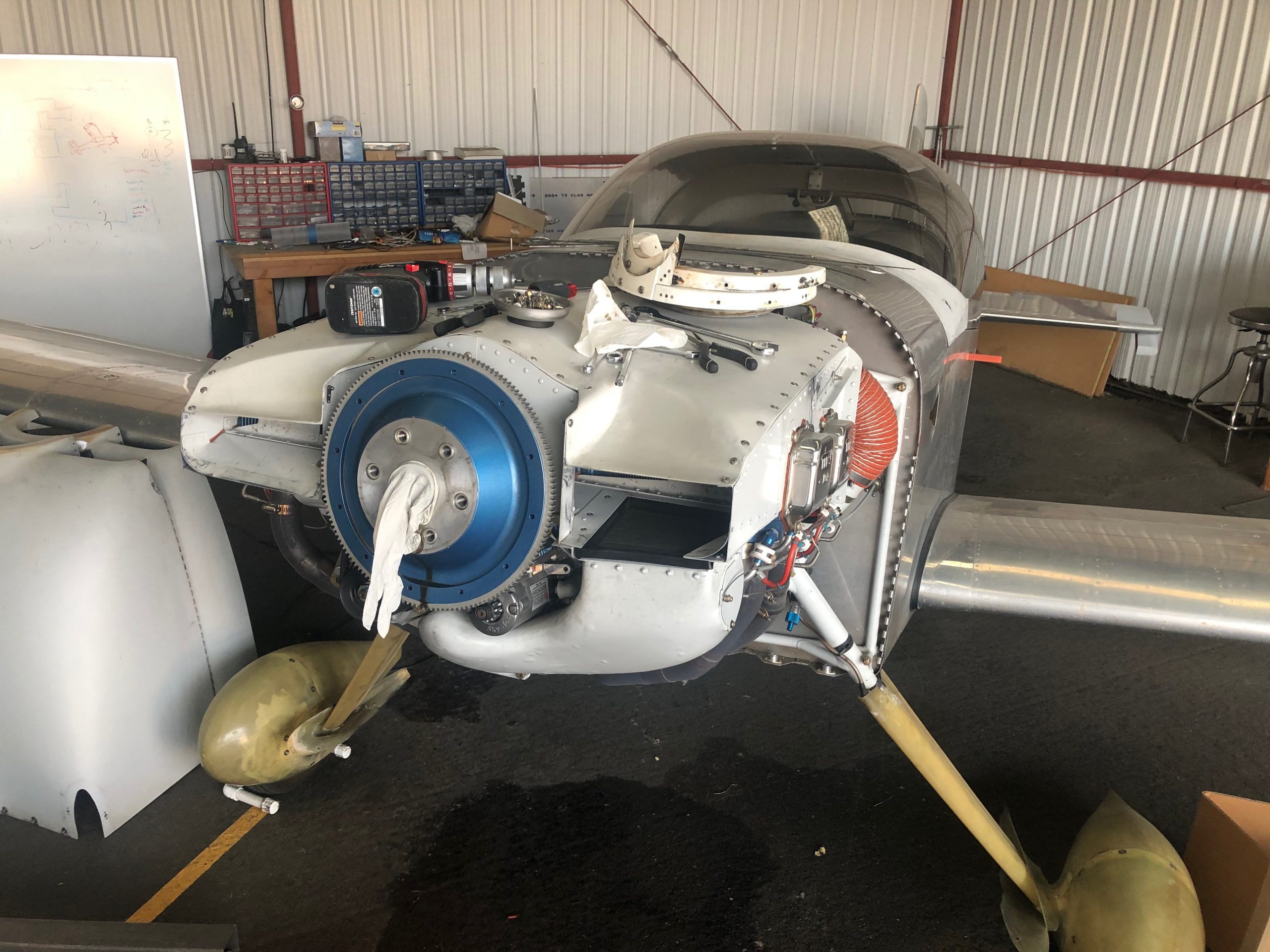
When everything was ready with the new prop, I pulled the old prop from the plane.

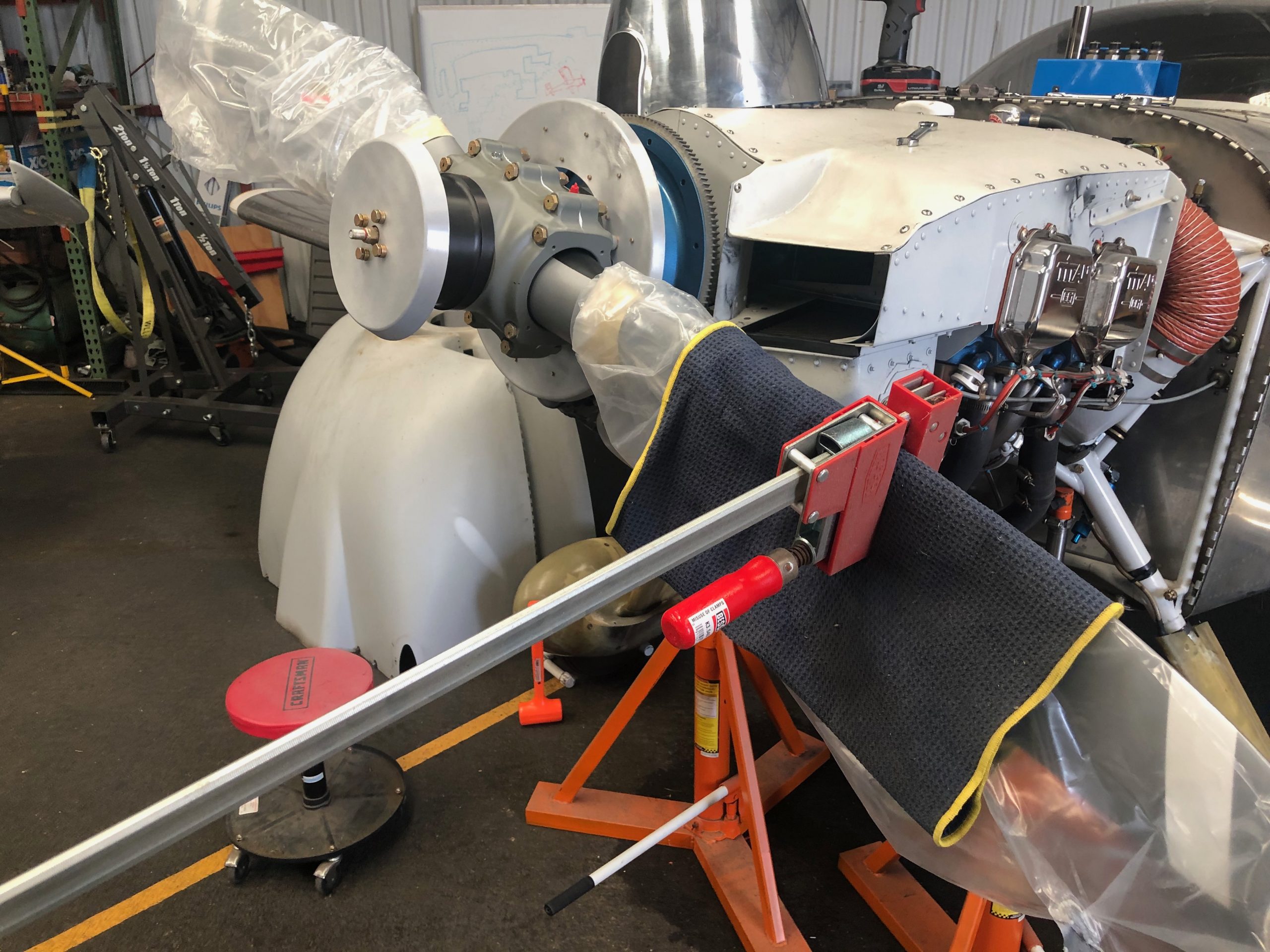
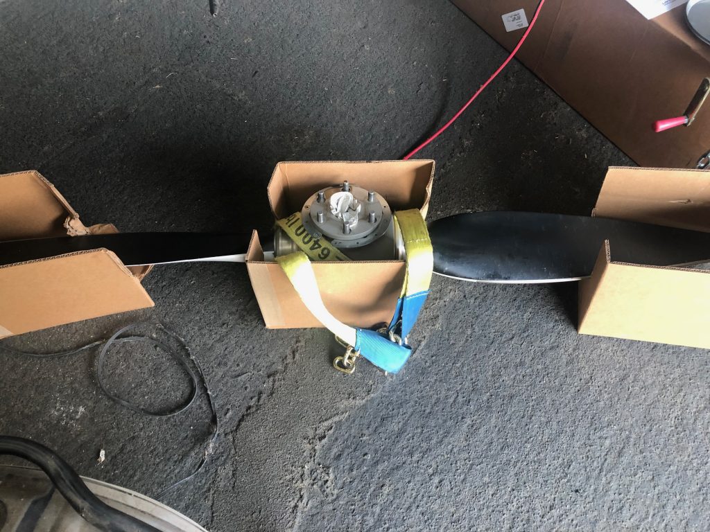
I’ve had some back pain recently, so I used this lifting sling with my shop crane to get the old prop off and install the new prop on the plane. This was far easier that trying to hold the prop with one arm while manipulating the bolts with my other hand.

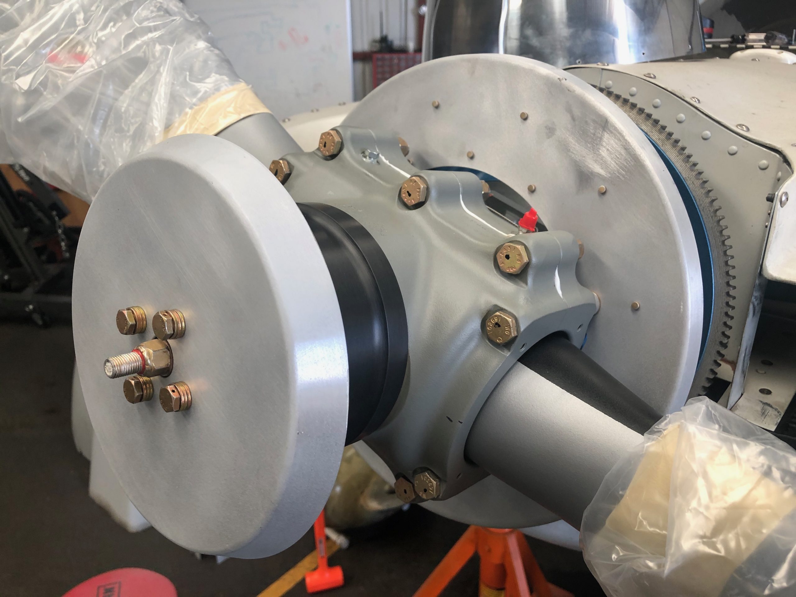
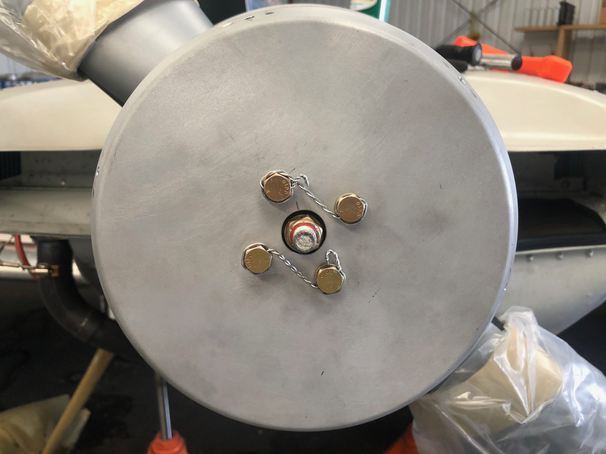
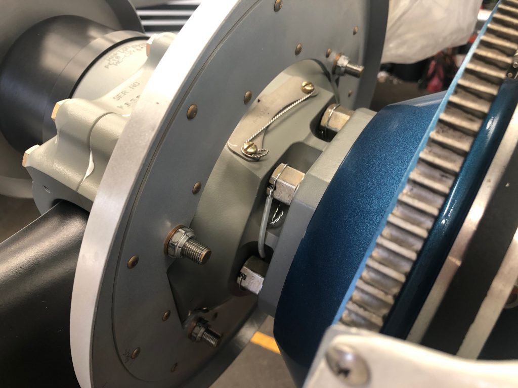
I taped the new bulkhead to the flywheel while installing and safety wiring the new propeller.

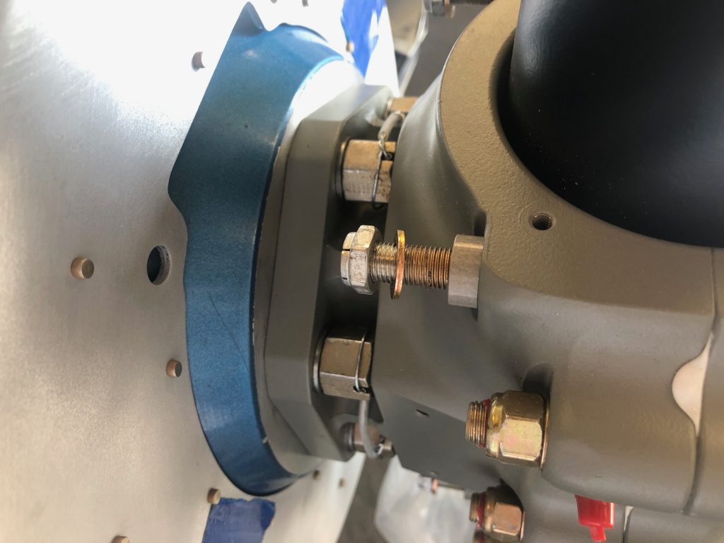
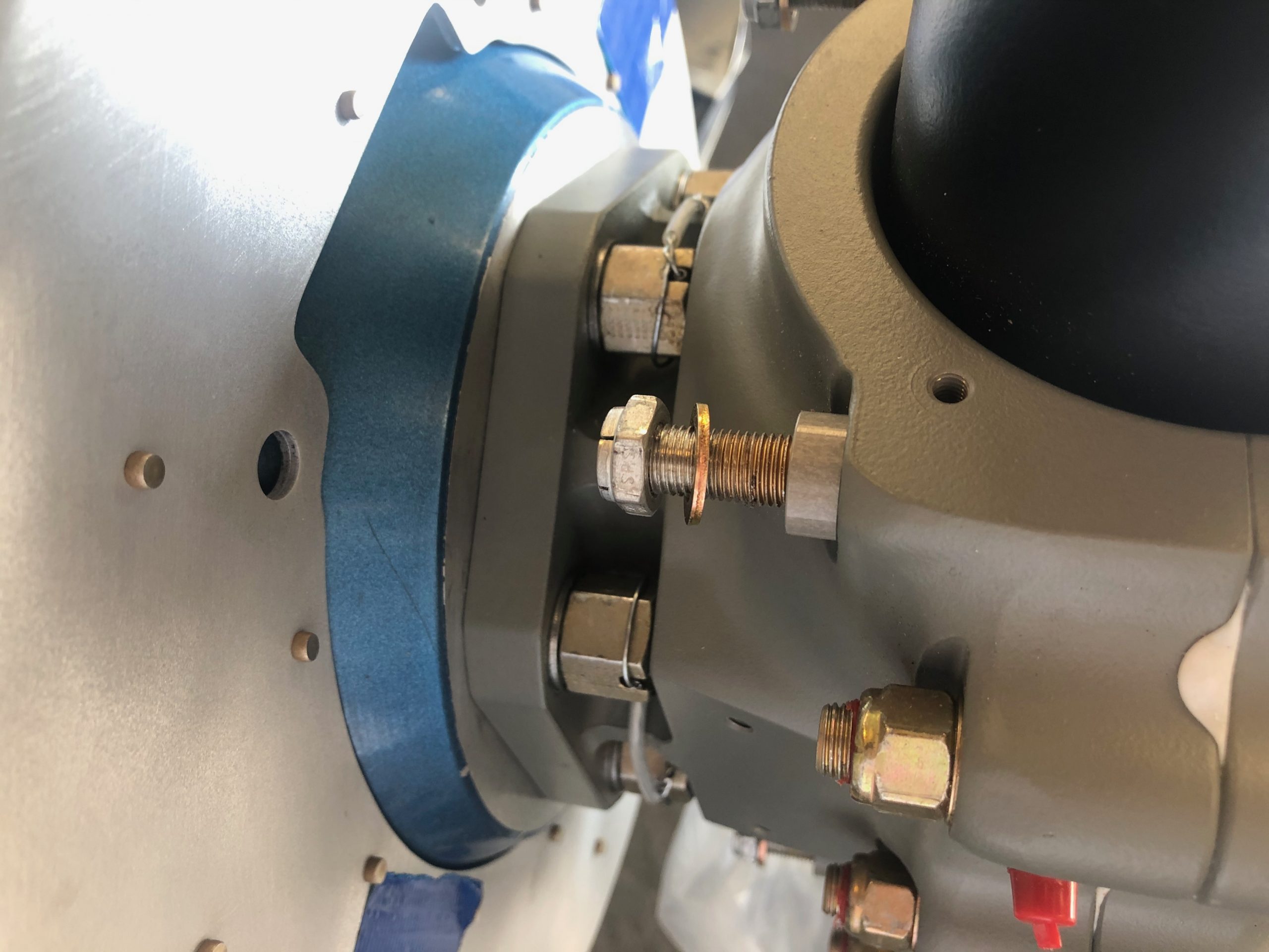
I then installed the rear bullhead to the hub retaining bolts and torqued them to spec.

I temporarily installed the front bulkhead so that I could begin fitting the spinner.

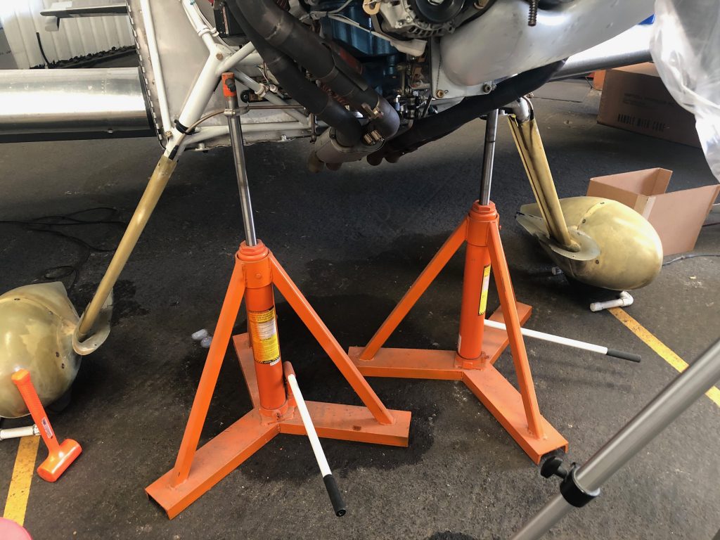
I needed to be able to turn the engine freely when fitting the propeller, but I needed it to be fairly stable. I used the same technique I did when fitting the wheel pants, and jacked the plane up by the engine mount. I then removed the lower spark plugs so that the engine could spin freely.

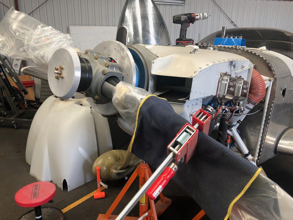
When fitting the spinner, I also needed to be able to cycle the blade from the fine pitch stop to the coarse pitch stop. I ended up using some padding and one of my Bessey clamps which worked perfectly. Here is the propeller at the fine pitch stop.

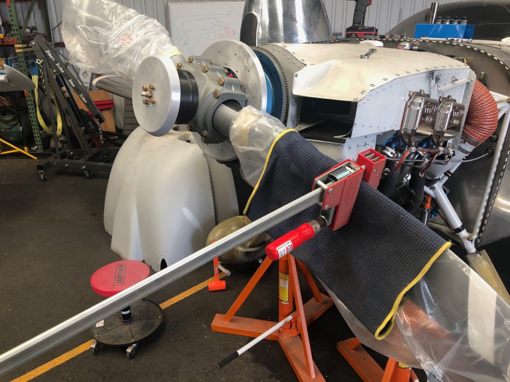
By just pushing down on the clamp (and holding the propeller tip to prevent it from rotating the engine), it was easy to twist the blade to the coarse pitch stop.

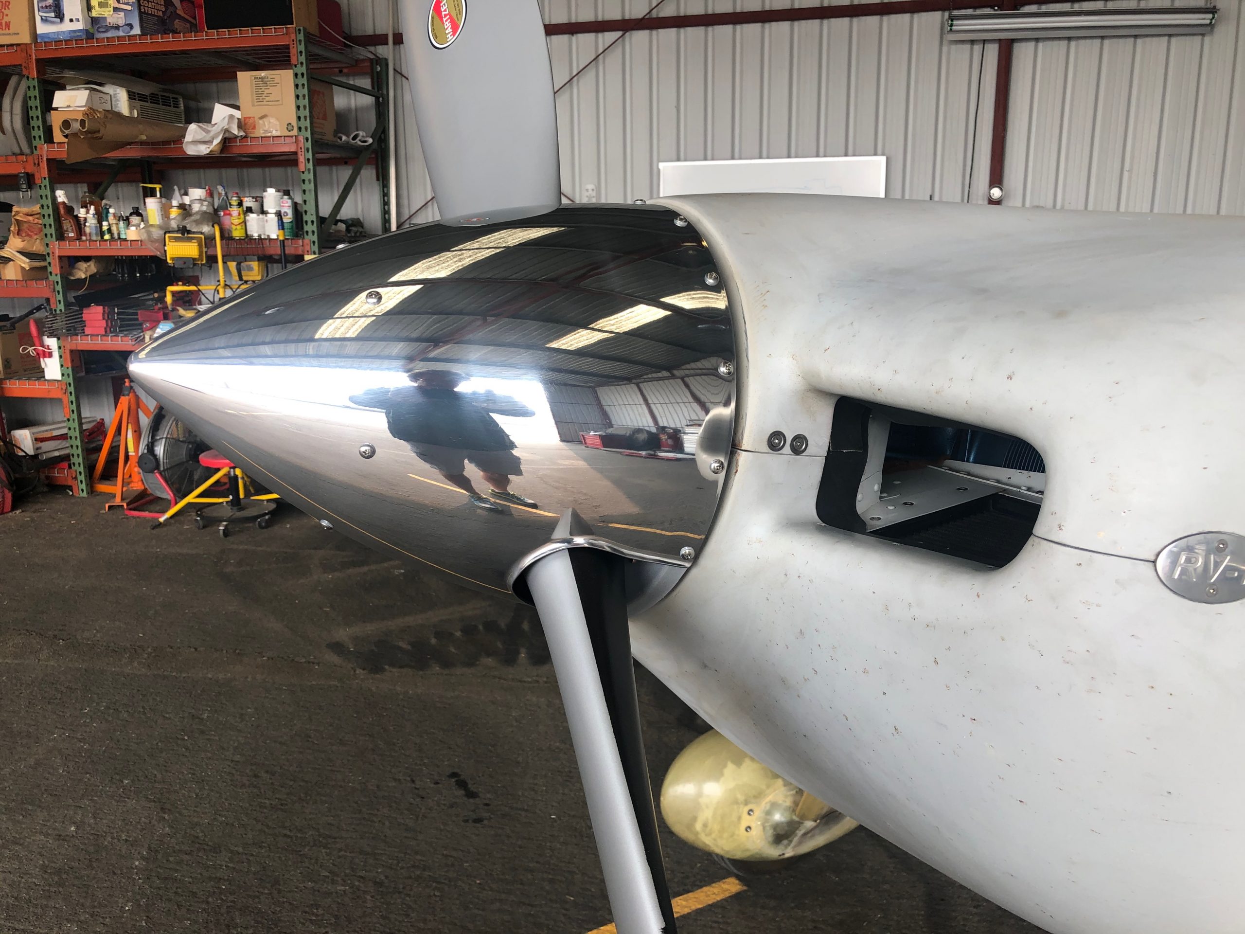
I’m using the Cummins Spinners spinner for this propeller. I emailed Alan back in the spring to inquire about purchasing one of these, but there was no response. Others online said that hadn’t been able to get ahold of him for over a year and a half! I gave up hope and ordered the spinner kit from Van’s, but just before install, I received an email out of the blue from Alan saying he had a spinner ready to ship! It took a couple of weeks to get here from Australia, but it’s worth it for the look of a polished spinner on the plane.

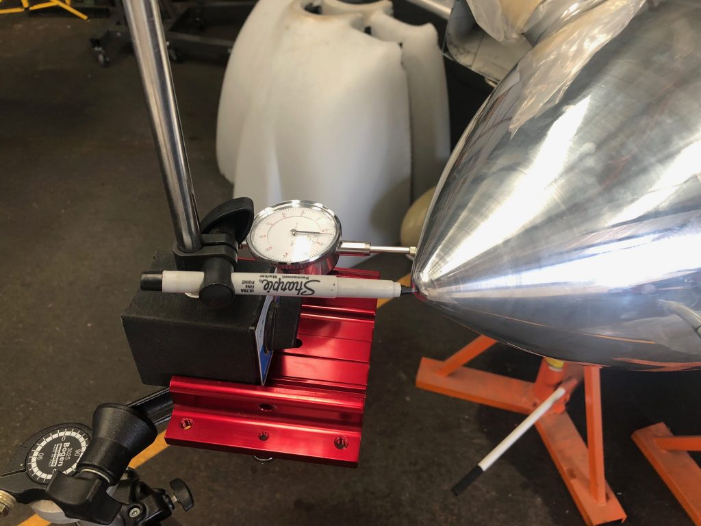
To ensure the spinner was centered, I used a combination of a marker at the tip and a dial indicator on the side to measure wobble. I think it’s impossible to get this to 0″, but I feel like I got pretty close. You couldn’t see any deviation with the marker tip and the dial indicator showed +/- 0.003″ deviation. Since the spinner is 0.065″ aluminum, that’s only about 5% of the thickness of the spinner!

After drilling all of the holes, I set the nut plates on the front bulkhead.

…then safety wired it in place.

My buddy Greg found a metal polishing place about 45 minutes from my house, so I dropped the spinner off and had them polish it to a mirror finish.

Interestingly, the prop clocks at a different location when the engine’s stopped. The old prop would be level after shutdown.

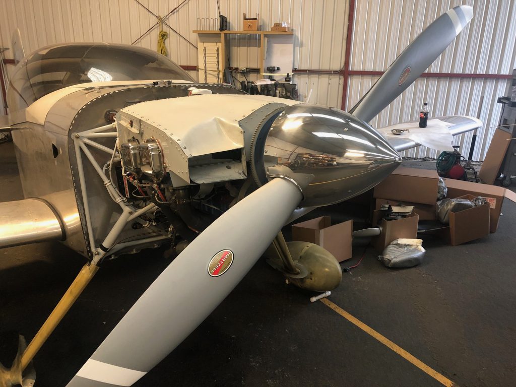
It looks like I’m going to need to raise the prop a small amount due to engine mount sag. You can see the misalignment of the spinner and cowling clearly here. The spinner sure does look sharp though.

I also need to fabricate filler pieces to fit behind the blades, but that can happen down the road a bit.

Replaced Pitch Servo Shear Screw

Sometime in the last couple of weeks, I noticed that the pitch servo wasn’t controlling the plane. I did some ground diagnosis and determined that the shear screw had sheared or some reason. I don’t recall any forces that would have caused this, so I can’t say why it happened. Dynon sent out a shear screw replacement kit a few days ago and I stopped by the airport this morning to install it and put the plane back together.

It’s amazing that this tiny cross section of brass is critical to the autopilot being able to control the aircraft.

I reassembled the control arm and tested the autopilot servo. Everything worked as expected, so I reinstalled the interior and updated the logbook.

Replaced Tailwheel

On one of my fuel stops on my recent trip back to TX and OK, I felt a weird vibration on landing, and it turned out that a chunk of the rubber from the tailwheel had broken loose. There had always been a defect in the rubber from the time the tailwheel was new, but I thought it was cosmetic. It lasted over 8 years and nearly 500 hours of flight time though, so I can’t complain too much.

In the meantime though, FlyBoy Accessories started selling this 4″ lightweight tire that is 13.5oz lighter than the 5.5″ tire above. That moves my CG an additional 0.13″ forward which should further help with the aft CG issue I’ve always had.

Added Heated Pitot Tube

I had my pitot tube freeze up at 15,000′ last summer in IMC. The Dynon algorithm doesn’t handle this situation very well; it’s supposed to fall back to GPS ground speed in the attitude calculation if the pitot indication is lost, but that apparently only works if the airspeed actually goes to zero. If the pitot tube is only partially frozen over and the airspeed is fluctuating, the indicated pitch attitude of the aircraft will swing widely and the autopilot will try to follow it. That’s frankly dangerous and Dynon should address this.

To reduce the likelyhood of this happening, I ordered a heated pitot tube and finally took the opportunity today to install it.

The heated pitot tube requires the installation of a heated pitot controller near the pitot tube. If I were installing this during the initial build, I would have mounted this to a nearby rib, but that was going to be rather challenging in a completed wing, so I decided to install it to the adjacent access plate. I drilled four mounting holes and dimpled them so that the screws sit flush. With the plate installed, none of the wires can rub on the controller or access plate nut plates.

I had to fish three additional wires out to the controller (power, ground, and sense wire to be routed to the EMS). Unfortunately, I ran the wing wires through a snap bushing in the fuselage and then into the wing conduit between the wing and fuselage. The additional wires wouldn’t fit through the snap bushing, so I had to cut it out and then use some RTV to prevent the wires from chafing on the edge of the hole. If I were building again, I would have drilled a larger hole in the side of the fuselage and left the wing conduit long so that it penetrated into the fuselage. It would have made running these additional wires substantially easier. The sense wire is not currently connected to the EMS as accessing it is quite difficult. I’m planning on adding the forward fuselage access panels at some point and will hook up the sense wire when I do that.

Upgraded to SkyView HDX Displays

I’ve been planning on updating from my SkyView Touch displays to the SkyView HDX displays for quite awhile, but was holding off until Dynon offered a trade-in plan. They recently did that, but the trade-in offer was disappointing, so I decided to just buy the new displays and will sell these. Here’s the old pilot side display.

And here’s the old co-pilot’s side display. These displays have worked perfectly and will be a great addition to some other builder’s plane.

For some reason, Dynon no longer supports the USB pins in the DB-37 connector. I was using these for the panel mounted USB ports so that both of the USB ports on the rear of the SkyView were available. I replaced the panel mounted USB ports with ones that just plug into the back of the SkyView displays. With those and the WiFi dongles, both USB ports are now used on each display. The only concern I have with this is that I have considered adding the video dongle so that I can add a camera feed, but perhaps I can use a USB hub if I do that.

The new HDX displays only use two screws per side instead of three. The upper one is fortunately in the same location, but the lower screw doesn’t line up with the existing nut plate, so I needed to install new nut plates above them.

Here’s one of the new displays installed. These displays don’t completely fill the hole in the panel, so there’s a cover plate hidden behind the lower lip of the display to cover the rest of the hole. You can see in the upper right where the panel mount USB port goes. It’s removed because the new ports with USB connectors on the other end are on order and should be here soon.

You can also see that the lower lip of the display obscures part of the panel labels. It’s not too bad from where I sit, but it would have been nice if this wasn’t an issue.

Here are both displays installed and configured. They’re somewhat brighter than the old displays and support a horizontal engine strip (as shown on the left display) as well as better touch based menus and screens.

10th Annual

I wrapped up the 10th annual on the RV tonight with about 611 hours on the plane. The plane has been virtually flawless during the past decade, but there are always some items that need to be repaired or replaced.

First up is the tires. I’m a little surprised I got 10 years out of the original set, but I’ve always let it roll out on landing and avoided heavy braking where possible. I did flip them to opposite wheels at one point to even out the wear, but they were pretty well worn now, so I decided to replace them. Here you can see the new tire on the left with the original tire beside it.

The snorkel had a bunch of cracking paint and flaking filler, so I removed it and sanded it back to the bare fiberglass before repainting it. I originally applied filler and sanded it to make it smooth, but the filler was delaminating. I’m not sure why it didn’t bond better, but it should be more robust now.

Finally, I replaced the air filter. These K&N filters are supposed to be lifetime filters, but some of the wires were starting to break on my old one for some reason.

SkyView Touch Displays for Sale

UPDATE: Both displays have been sold.

I’m selling my SkyView Touch displays; they are both D1000T (10″) displays. They are in nearly new condition, have no marks on the displays, and everything works perfectly. I’m selling them for $1,800 each or $3,500 for the pair. I’d prefer to deliver them in person for cash anywhere near northern CA, but I’ll ship if the money is sent via wire transfer to me. Please contact me at rv7@jasonbeaver.com if you’re interested.

They have approximately 500 hours on them and have been completely trouble free. They are serial numbers 15013 and 15015 that I’ve had since Dynon offered the upgrade path from the original SkyView to the Touch displays in 2015. I’m only selling them because I bought new HDX displays last year.

They include both the map and VP-X licenses, two of the SV-NET-TEST cables and a FlyDynon sticker.

Here are a few pictures of the units before I took them out of my RV-7.

Here is a closeup of 15013, front:

and back:

And here is 15015, front:

and back:

I tried to take some video of the front of each display in the light to show that there is not a mark on either display. Here’s 15013:

And 15015:

Here are the goodies I’m including:

They’ll even come packed in the original boxes from Dynon!

Dynon Unheated Pitot Tube For Sale

Update: Pitot tube has been sold.

I upgraded my pitot tube to the heated version, so I’m selling my unheated one. They’re $252 from Dynon, so I’m selling this for $100. The tubes have been cut shorter, but there’s plenty of length to attach a flare nut or you can slip flex tubing over the aluminum tubing and secure.

You actually want the tubes fairly short so that you can insert/remove the pitot tube without having to flex these tubes. See how I routed the pitot tubing here:

Pitot/AOA Tube Routing

Replaced Garmin GTN-635 Internal Clock Battery

I recently received a “Low internal clock battery” alert on my GTN-635. As I understand it, this can cause the GTN to take much longer to acquire it’s location, and this indeed seemed to be the case.

The Garmin uses a 14250 battery, not something I could easily find locally, but Amazon had next day delivery.

After removing the GTN, you’ll find 6 Phillips screws on top. All of the them are the same length except for a short one in the middle location on the right side.

The battery holder is right in the middle of the board and you’ll need a tiny flat-head screwdriver to pry up the catches on each end. After that, it’s a quick swap and everything can go back together.