Finished Pilot Stick Wiring

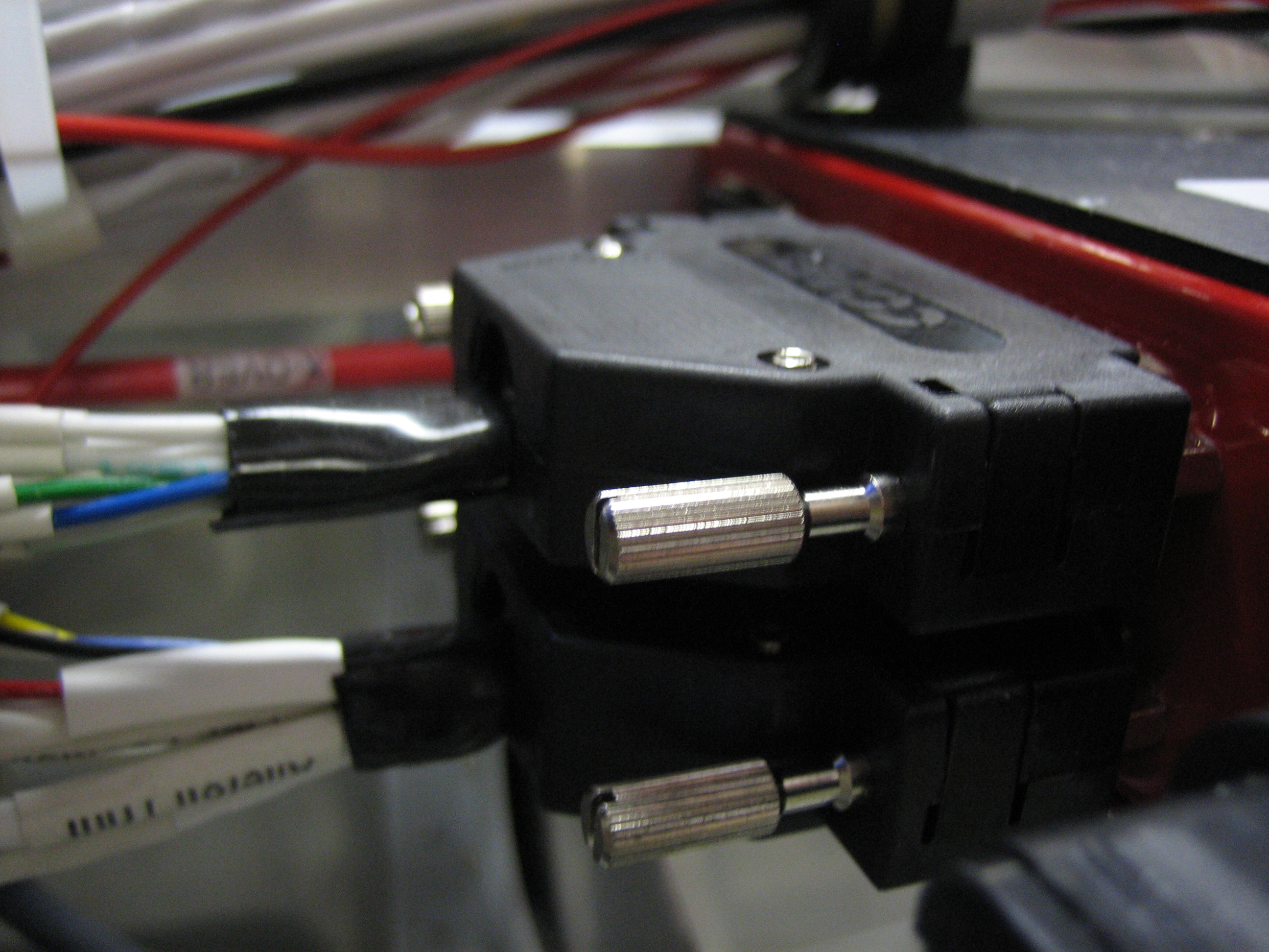
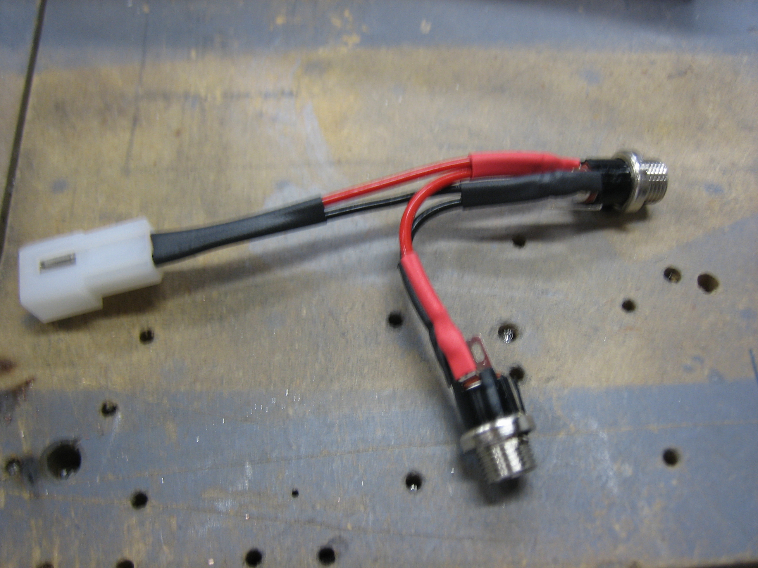
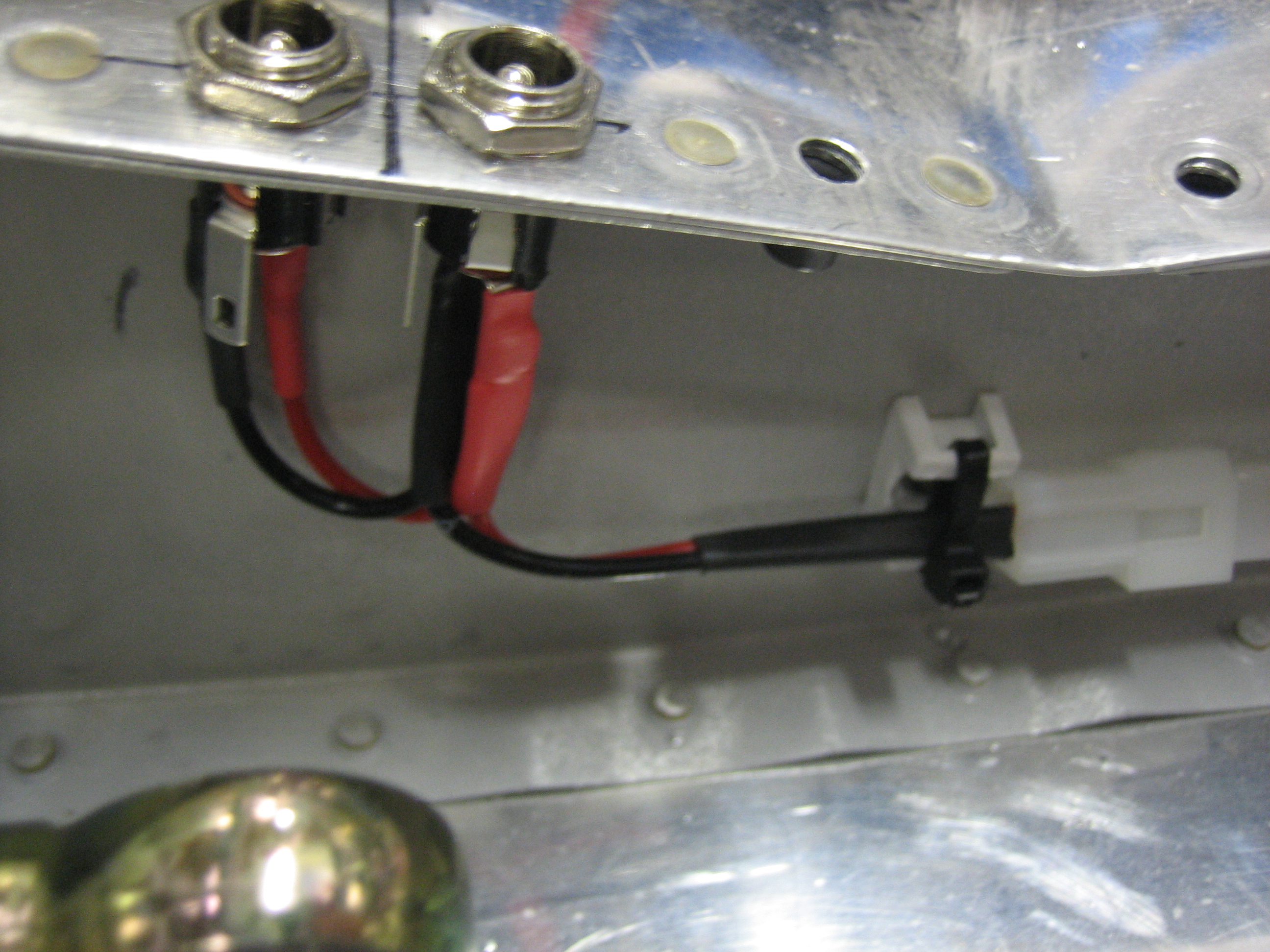
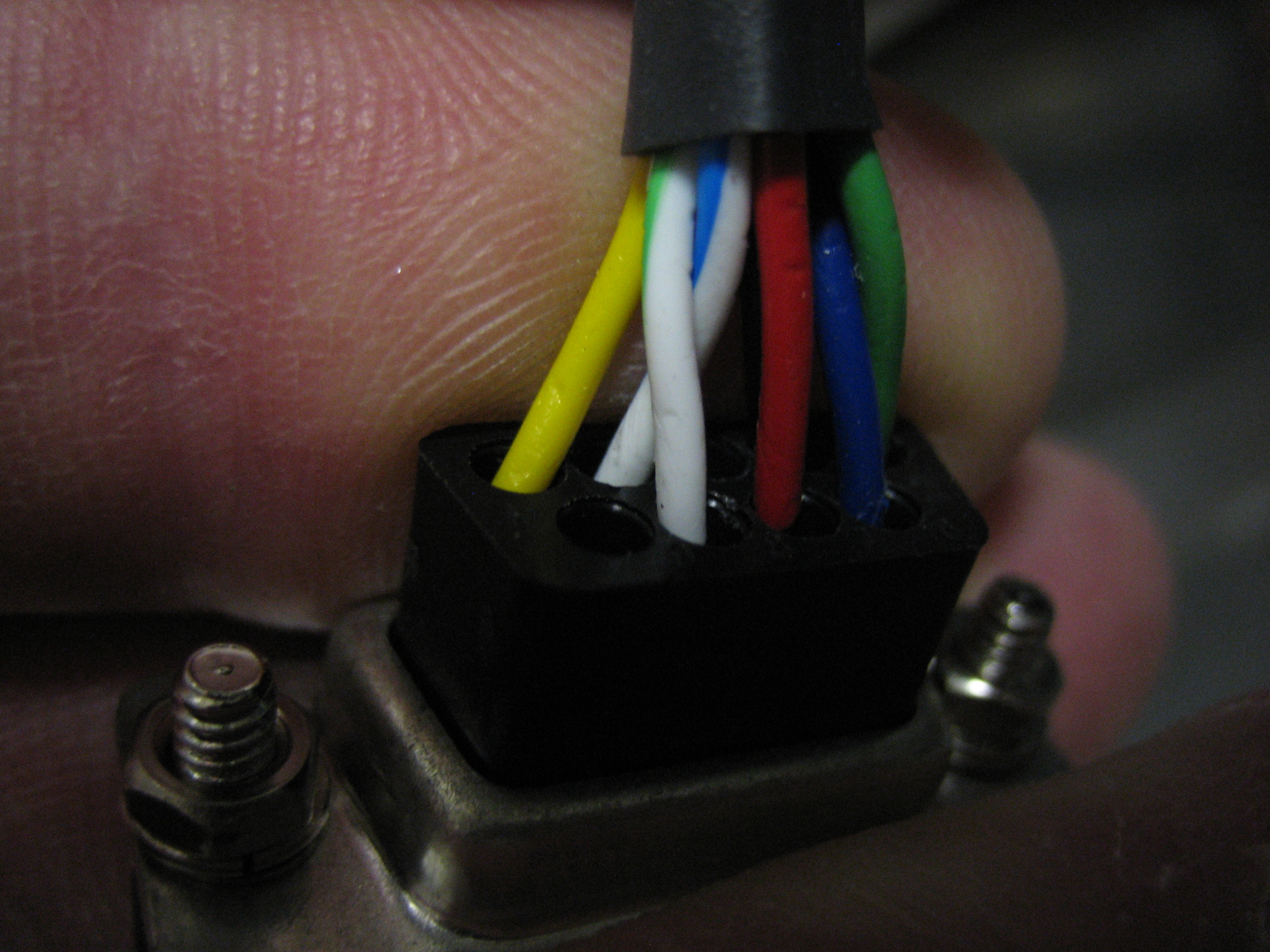
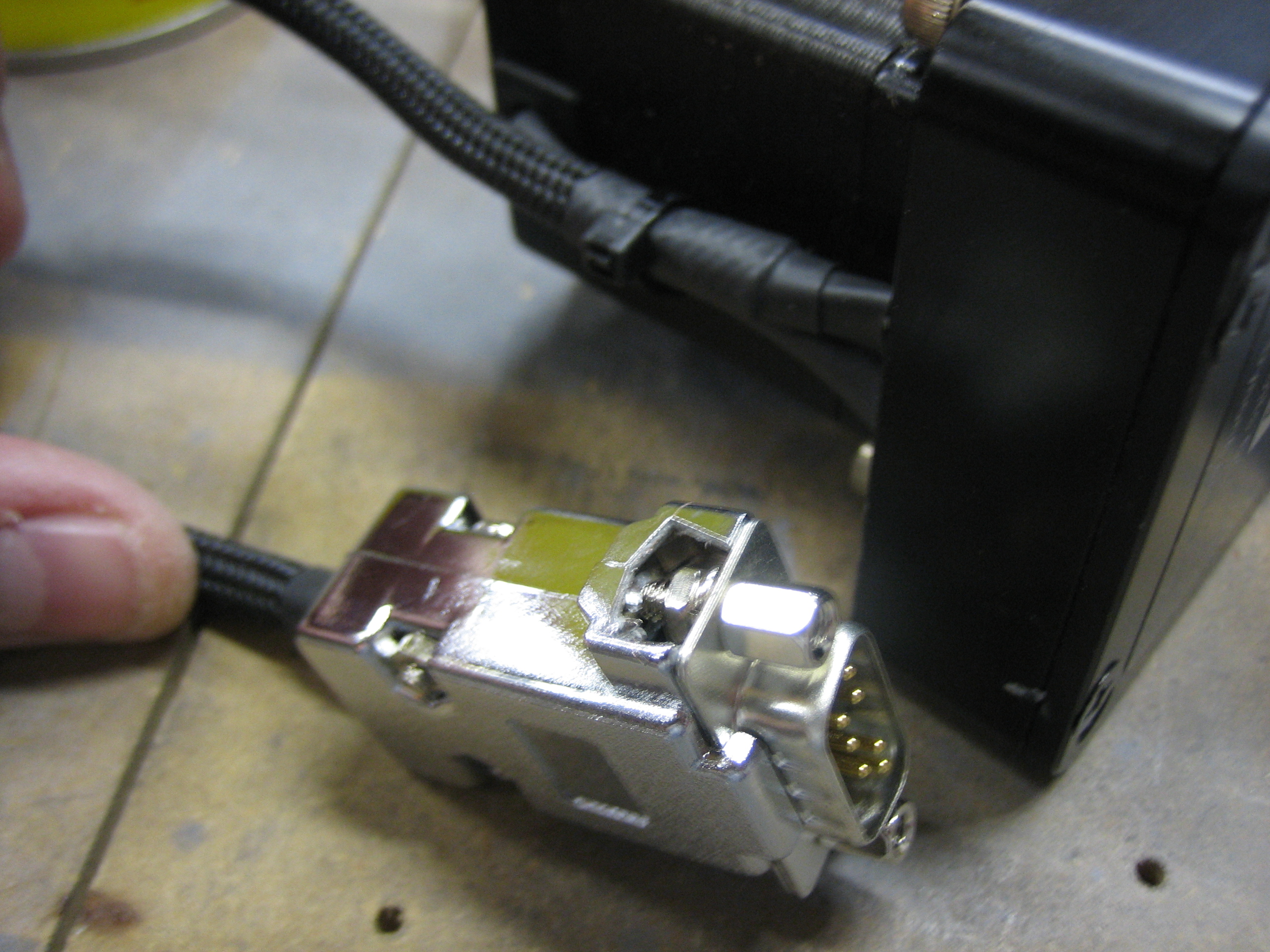
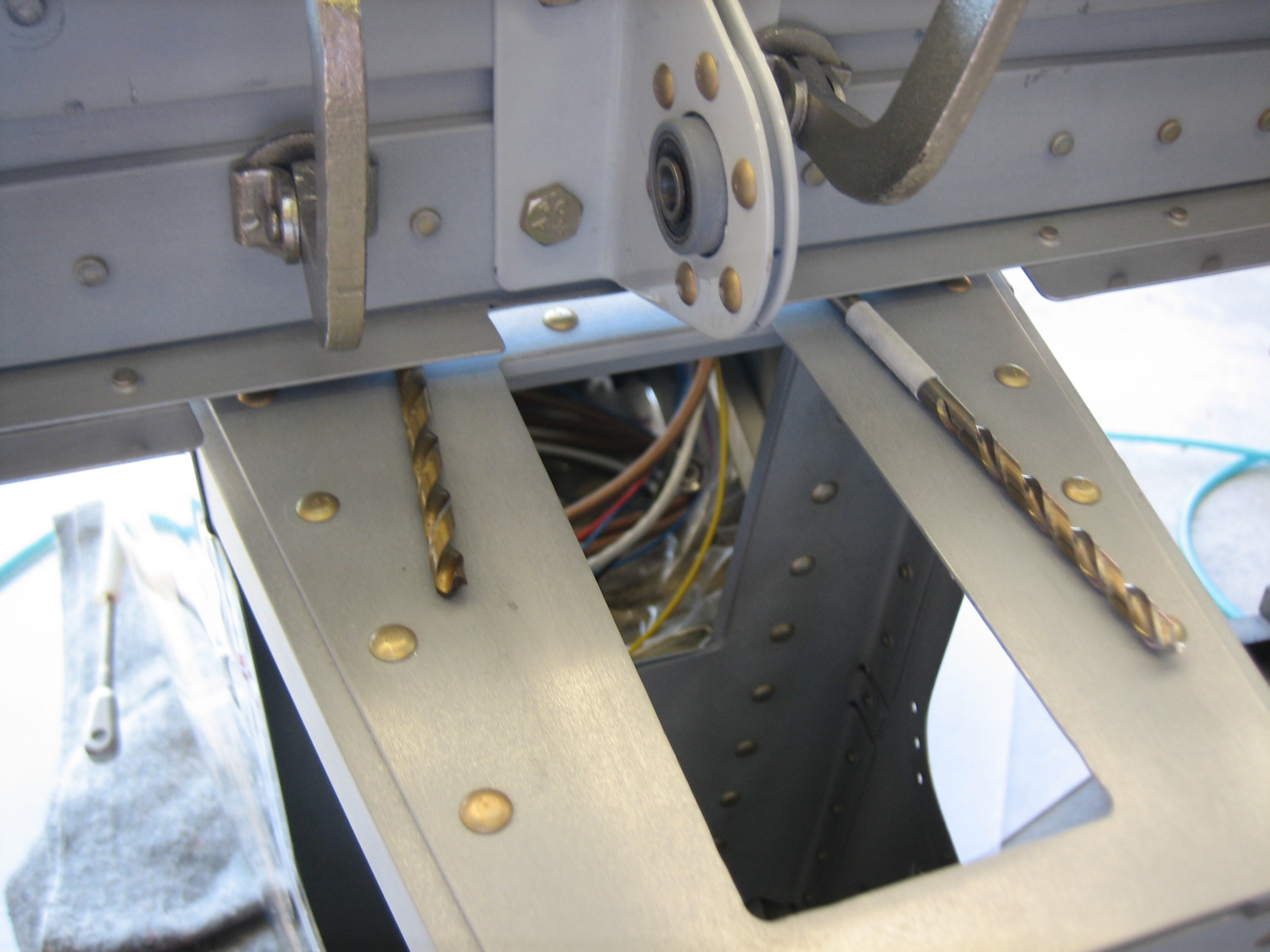
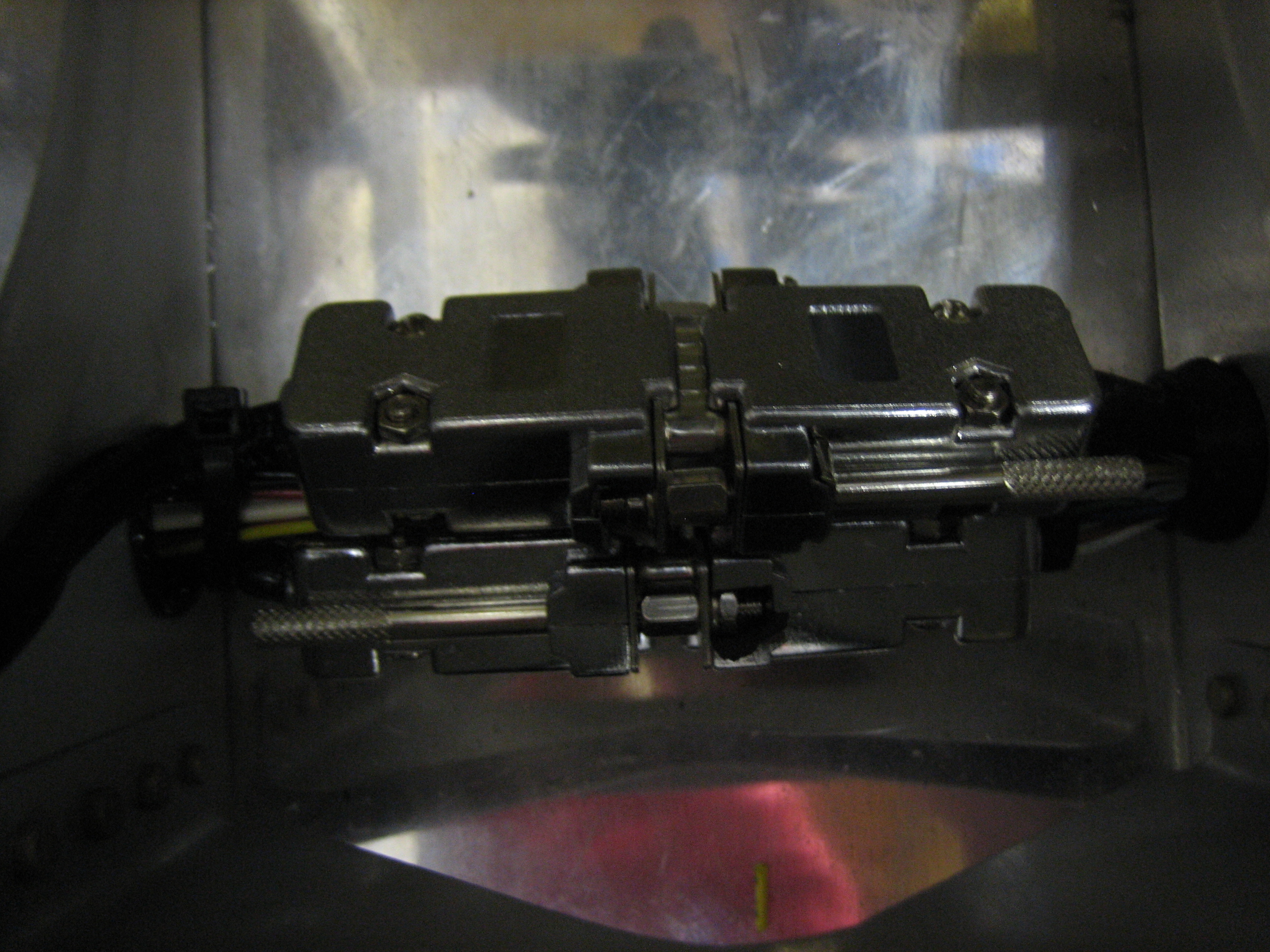
I finished wiring up the pilot’s stick grip tonight.  The bundle from the stick terminates at the connector on the left so that the stick can be removed without having to disassemble any of the wiring.

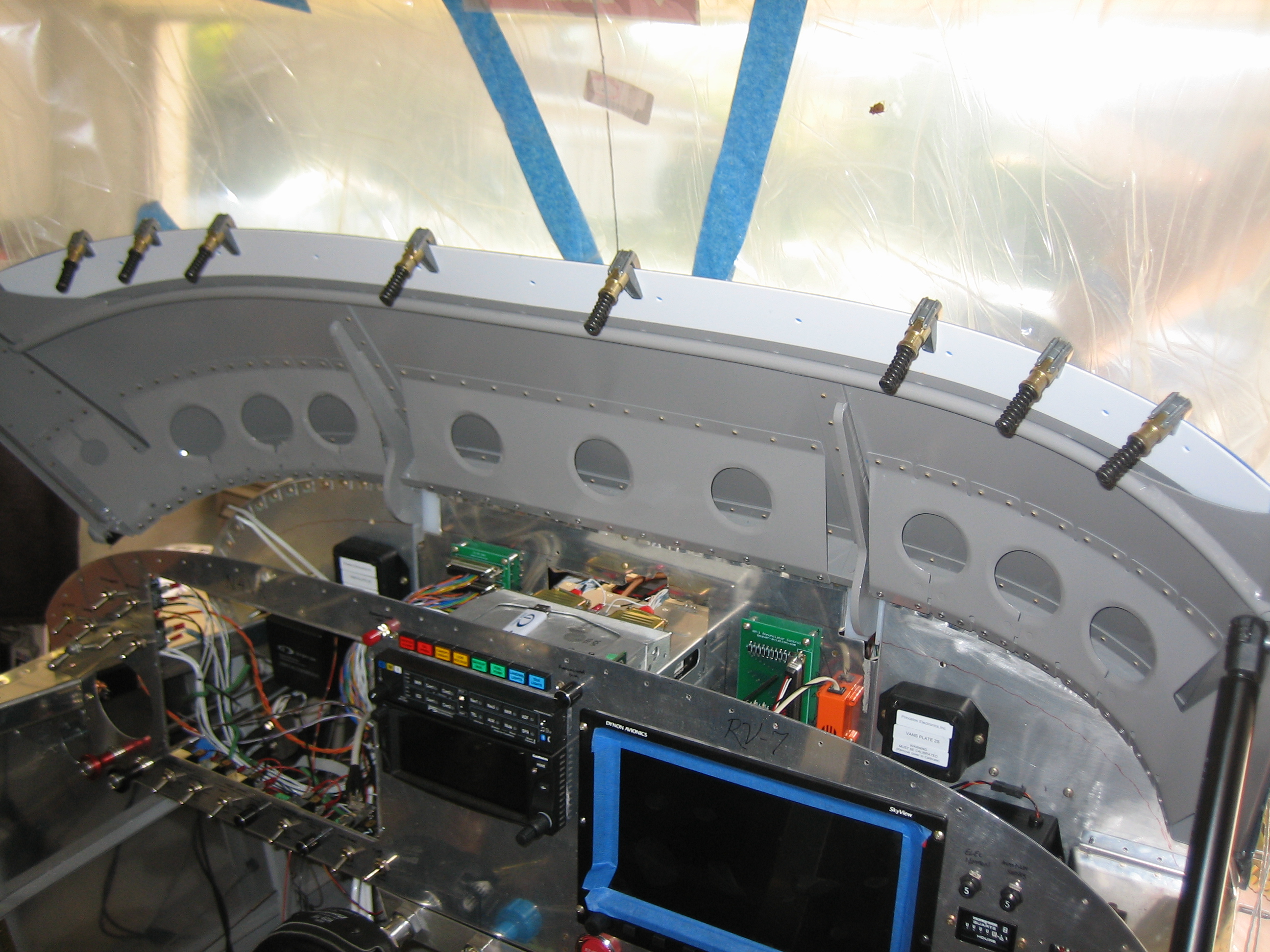
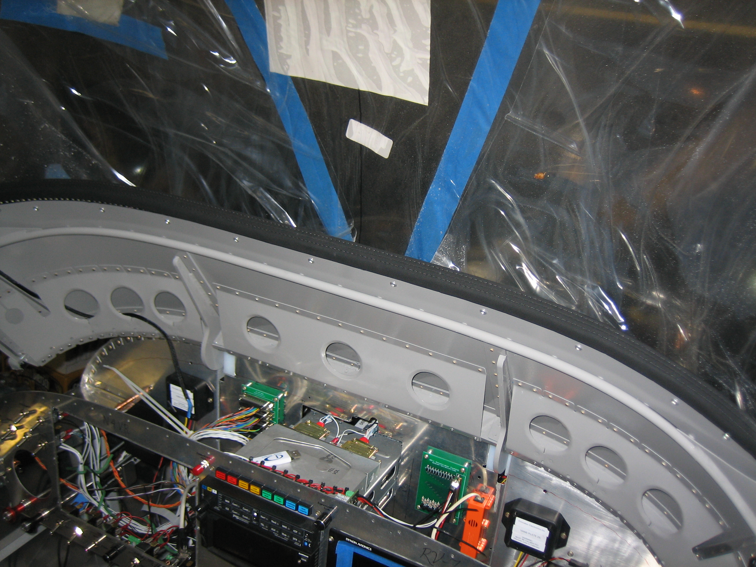
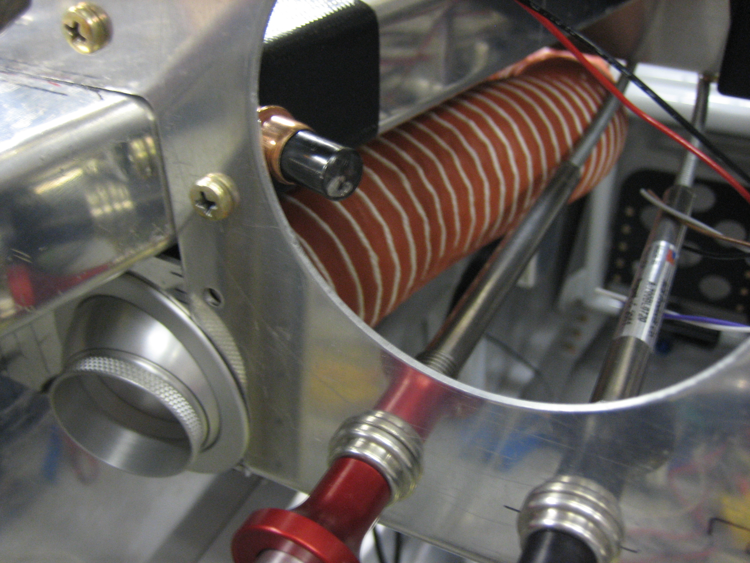
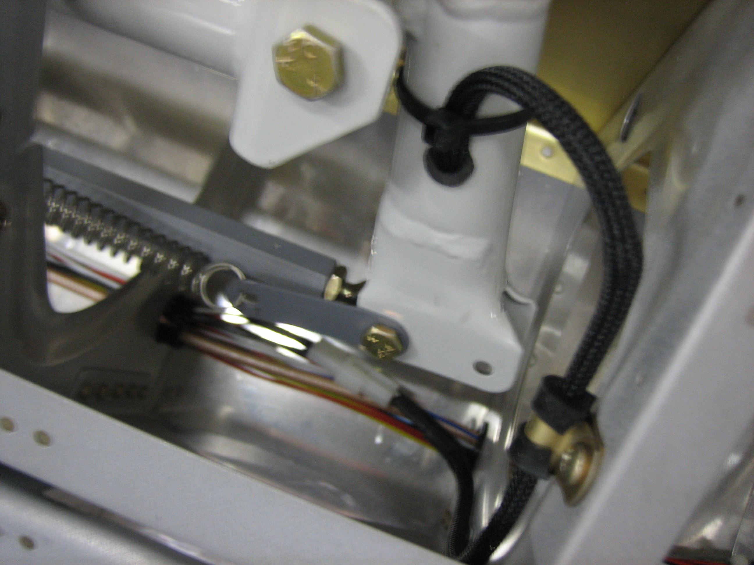
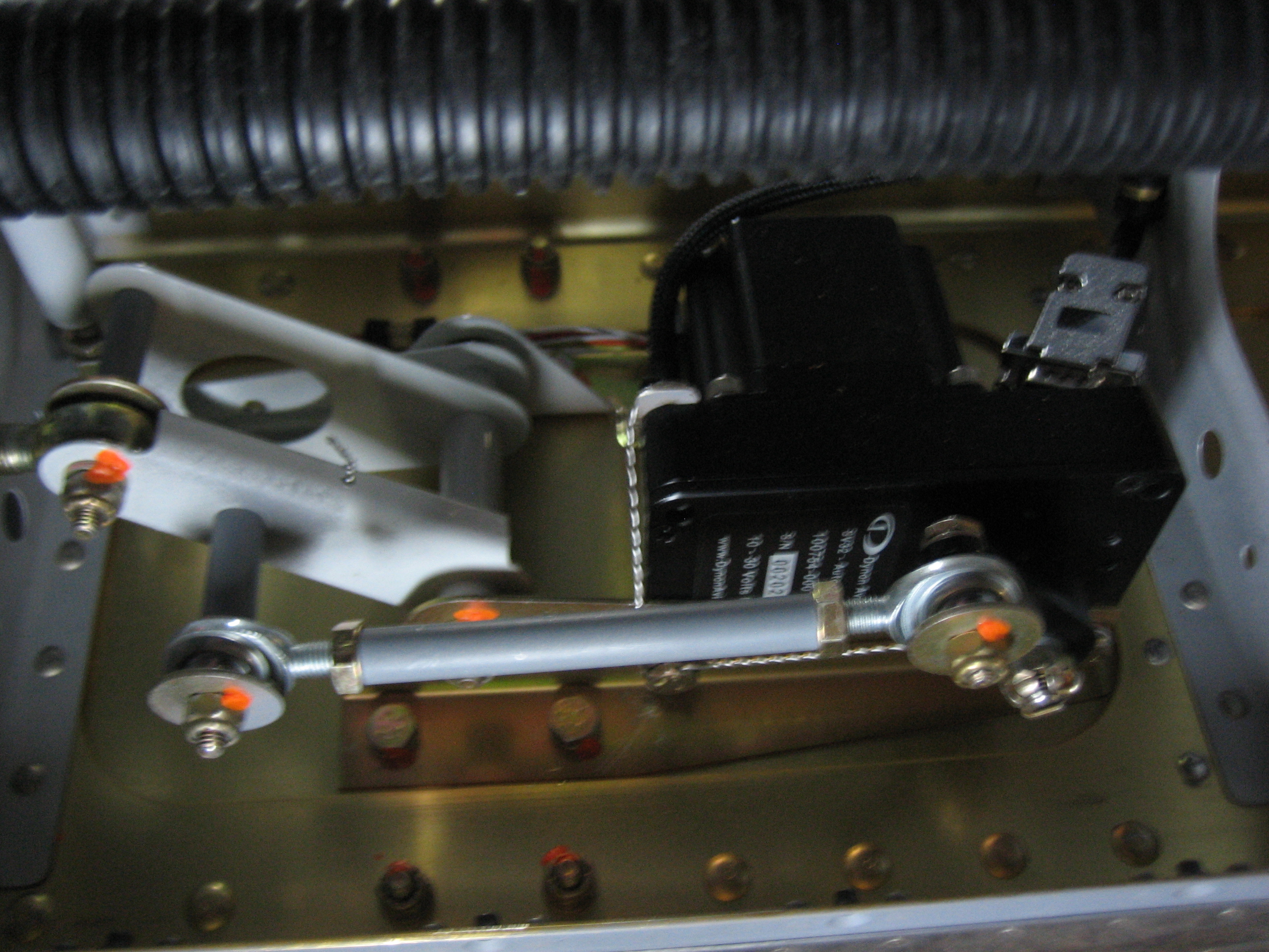
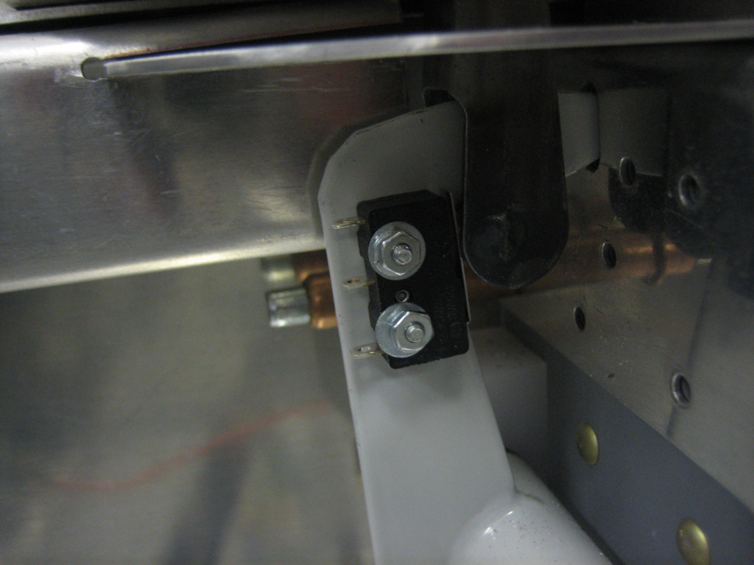
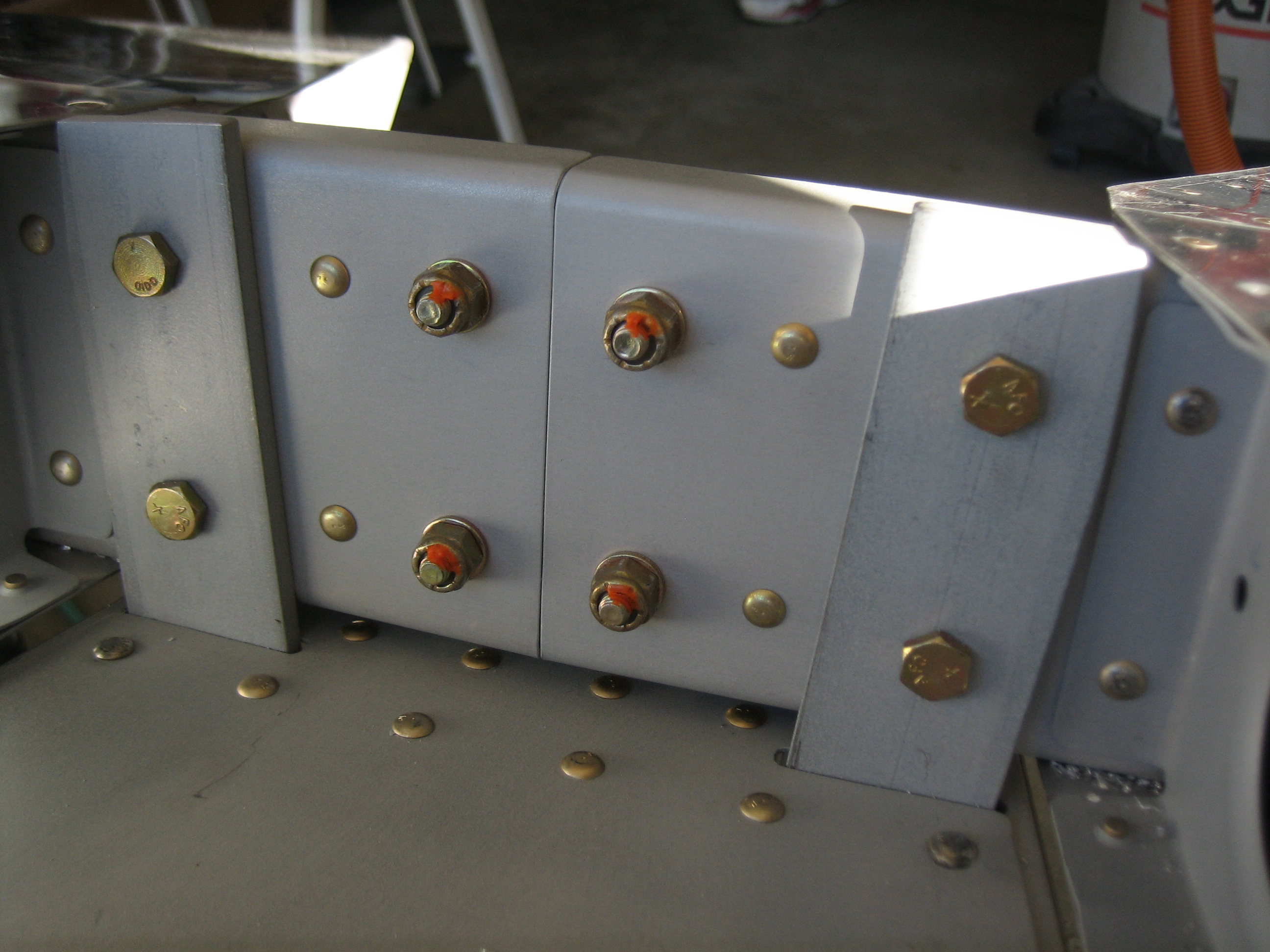
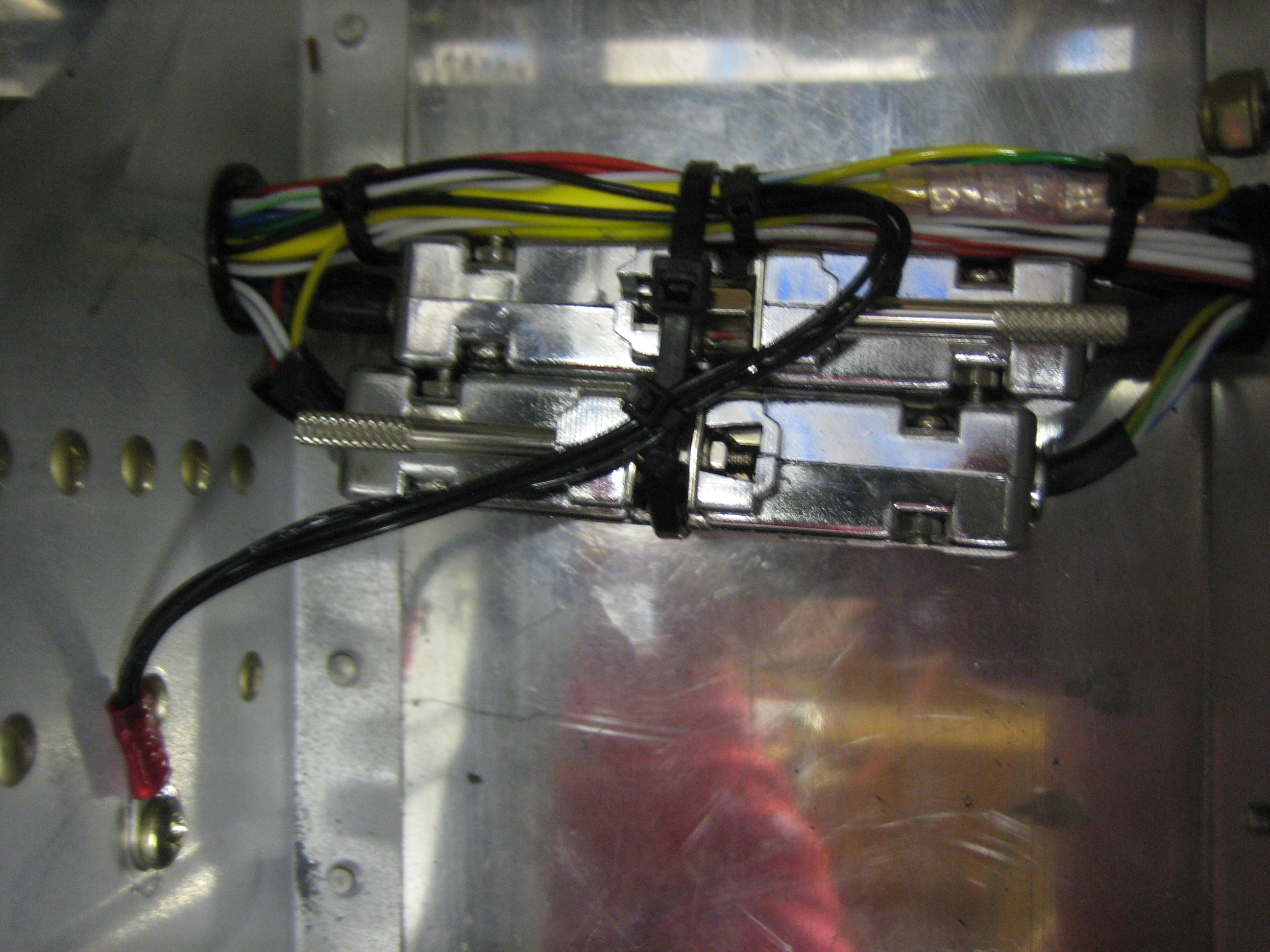
In the next bay to the right, the ground wires split off and are grounded to the rib with a #8 screw since these are just ground sense wires.  I cleaned off the primer and used some Noalox anti-oxidant compound to ensure a good ground.  The yellow wires from the autopilot servos are tied together here and connected to ground through a 5kΩ resistor which allows the SkyView system to detect a broken autopilot disconnect wire.  They can also be shorted directly to ground through the CWS button on the stick which triggers the CWS and autopilot disconnect functionality.  Six of the wires (four trim wires and PTT wires) proceed from here up behind the subpanel.

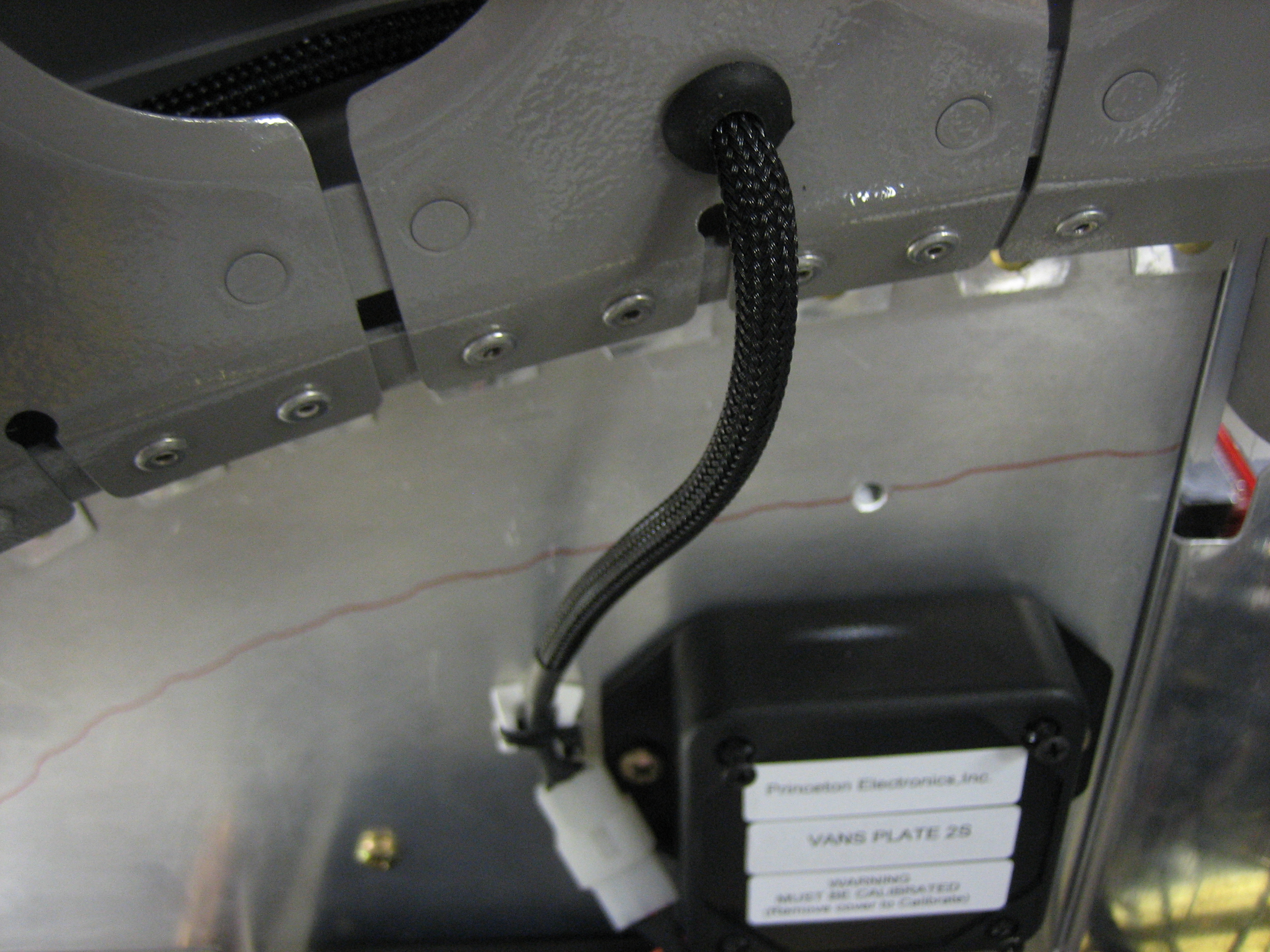
With the final four connections made on the J2 connector, I installed the connector shells on J1 and J2.  Finally, I fired up the avionics and verified that I can transmit on the radio, control the autopilot, and drive the trim.  I did notice one oddity though.  When I first tried running the trim with the coolie hat, the aileron trim ran backward from the way it should have.  I hooked up the laptop and double checked that the coolie hat was wired up correctly and it was.  Reversing the motor addressed this problem, but created another.  When I go to the VP-X page on the SkyView and scroll to the roll trim device, the Left and Right buttons at the bottom of the screen now are reversed.  I also configured the trim widget on the engine control page and noticed another oddity, when I trim all the way to the right, the arrow moves all the way to the left.  Looks like it’s time to contact Dynon again.

Fabricated Headset Jack Brackets and Worked on Pilot Stick Wiring Bundle

I fabricated the headset jack brackets from some 0.040″ bent sheet.  These were cut from the original engine control bracket that Van’s includes in the kit.  I drilled the holes 1″ apart and drill three staggered holes to mount the brackets to the bulkheads.  Here’s the copilot’s bracket.

And here’s the pilot’s bracket.  These are mounted high enough that they’ll never accidentally be kicked or bumped, but low enough that you can still lean over just a bit to see when plugging in the headset.

I then wired up the pilot’s jacks.  The mic jack is on the top and includes two extra wires that are routed to the pilot’s push-to-talk button.  I then routed those two wires back to the pilot’s stick.

There is just over 1/4″ of clearance between the plugs and the face of the bulkhead.  The interior side panels will mount to this face and are approximately 1/8″ thick.  This will keep the plugs fairly tight against the side panels without causing them to rub against it.

Here’s how I ended up deciding to secure the stick wiring.  The bundle exits the bottom of the stick between the bearings and then wraps around the end and back up the side where it is anchored with a couple of zip ties.  It then curves over and is anchored to the adjacent rib with an adel clamp.

Because the bundle curves away from the stick pretty much right at the pivot point, the length hardly changes as the stick is moved.  The position with the least slack is with the stick in the aft left position.

Moving the stick to the fore right position creates the most slack in the bundle.  I’m really happy with this arrangement as the bundle has very little flex and has no chance of interfering with the control stick or aileron trim.

Finished Aileron Trim and Started Wiring Seat Heaters

I finished the aileron trim by installing the right clip and attaching the spring between the clip and the servo arm with some 0.041″ safety wire.

I adjusted the length of the safety wire so that the sticks naturally rest vertically when the servo arm is in the neutral position.  I ran the trim to both ends and moved the sticks in all directions to ensure that nothing could snag or interfere with the sticks.  I had to adjust the bend in the servo arm slightly to keep the safety wire from interfering with the rib just to the right of center.

Next up, I installed the dimmers for the seat heaters.  The control cable to the right is for the cabin heat, so all of the heat controls are located together.

I prepped the wires and attached them to the dimmers.  It’s too late to run these wires tonight, so I’ll finish these off tomorrow.

Installed Control Sticks and Started Aileron Trim

With the engine controls in their final location, I marked both sticks and cut them off.  I’m using the teak grips, so they extend the sticks a couple of inches or so.  For reference, I cut 4 1/4″ off the pilot’s stick and 3 11/16″ off of the co-pilot’s stick.  This puts the bottom of the grips (and therefore the hand) the same distance from the pivot point for either stick.

I needed to cut this much off to ensure the grip clears the throttle when at idle.  This gives me a comfortable clearance even with my finger on top of the grip.  It might be a little tight if my hand is resting on the throttle at the same time, but I don’t want to cut off any more than I need to.

I installed both sticks and the push-rod that connects them.

The pushrod transfers the aileron control between the sticks and between the wings.  I did forget to install the aileron trim clips the first time I installed the pushrod.

Here’s where the clip should be installed.  When the ailerons are in the neutral position, the clip points at the end of the trim servo arm.  The clip is bent out away from the pushrod just enough that the trim spring doesn’t touch the pushrod.

When the stick is in the full forward and left position, the spring is attached to the trim servo arm so that the spring is very slightly extended.  This prevents the spring from ever going slack regardless of the position of the controls.  There will be another spring tying the co-pilot’s stick to the other hole in the trim servo arm.

The bundle of wires from the pilot’s stick exits through the bottom (between the bearings) and is tied to the connecting pushrod in a couple of spots to prevent interference with the trim spring and the adjacent rib.  The bay just inboard of the stick will provide room for the wire bundle to flex as the stick is moved.

Installed Control Cables

I installed the control cables in the bracket and clamped it to the panel with a couple of c-clamps.  You can see that I offset the bracket to the right so that the three engine controls are centered on the panel.  I did this to give myself more knee room.  It will be very rare that I fly with someone as tall as me (6′ 4″), and no one will ever take off or land from the right seat, so their knee room isn’t as important.  The small knob on the right is the parking brake.

The throttle cable comes through the hole below the cabin heat box.  I haven’t installed the eyeballs in the firewall yet since I’m just trying to make sure the cable lengths are correct and determine where they will run.

The throttle cable attaches to the custom bracket I made and then to the throttle arm.  The length and fit of the parts is perfect.  I can easily adjust the throw so that the knob is sticking out about 1/8″ when the throttle bracket hits the stop (you do this so that you know you’re hitting the control arm stop and not just the cable stop).  I’m going to replace this all-metal stop nut (which is acceptable) with a drilled bolt, castle nut and cotter pin (which is preferred).

The mixture cable penetrates the hole just under the manifold and runs just above where the oil cooler will be mounted.  I’ll use some adel clamps to keep everything from rubbing on the oil cooler flange.

The cable then drops below the engine mount tube holding the oil cooler and on up to the mounting bracket.

The forward end of the cable connects to the mixture idler arm.  I had to lengthen the small pushrod at the other end of the idler arm to get the mixture control arm to contact the stop, but in the end, it works beautifully.

The prop cable penetrates the far left hole (right in this picture since we’re looking aft) at a pretty severe angle since it needs to mount to the governor on the back of the engine.

The end of the cable attaches to the governor control arm.  After some adjusting, the throw on the prop governor is perfect as well.  I do need to replace this bolt though.  It’s too short and I want to use a castle nut and cotter pin just like the other control cables.  I did have to reverse the bolt from the orientation specified in the plans since it’s just about impossible to insert/remove the bolt the other way since there is not enough space between the control arm and back end of the governor.

Finished Annunciator Lights (Almost)

I wired up the remaining annunciator lights (other than the “Canopy Unsafe” light).  The final three were the landing and taxi lights as well as the fuel pump.  Unfortunately, this unveiled a flaw in the annunciator control circuit I designed.  Basically, for annunciator lights that are triggered high, I was assuming the transistor base voltage would be shed through the load when the load was turned off.  The problem is that for certain types of loads (e.g. LED lights), the load resistance is pretty high at low voltages.  This has the effect of causing the transistor base voltage to fall pretty slowly after the load is turned off, which causes the annunciator light to dim slowly.  I really need to couple the base and emitter with a resistor to provide an alternate path for the base voltage to drain.  I’ll have to redesign the circuit and have new PCBs made.

Wired Electronic Ignition and Tested ELT

I received another order from Aircraft Spruce with some 18AWG shielded wire.  The piece that came with the electronic ignition wasn’t long enough to run from the unit to the switch, then to the breaker, and finally to the battery bus.  I used a solder sleeve to join the shields of two pieces and then connected their center conductors to the NO side of a 1-3 switch.

From the switch, the wire runs to the breaker where a similar connection is made.

The center conductor of the shielded wire is connected to the battery bus (the upper right fuse here).  Another solder sleeve is used to connect an 18AWG black wire to the shield.  The installation manual specifies that this should be directly connected to the battery, but I’m trying to limit unprotected wires in the aircraft as much as possible.  Connecting this here adds only a couple of connections over the recommended wiring method, and these are very high-reliability connections.

That black wire then runs to the ground block.  I drilled a hole through the firewall to anchor the other end of the ground block and attached the wire there.  I doubt this is significantly more reliable than one of the fast-on connectors, but it’s about as reliable a connection as you can make short of connecting it directly to the battery ground terminal.

I had a little more energy, so I quickly fabricated the ELT data verification circuit and hooked it up to the wire that I left sticking out of the ELT connector.  I fired up the avionics and verified that after the GTN had acquired a GPS fix, the light started flashing about once a second to indicate that the ELT was receiving valid position data.

Hooked Up ELT Audio Box and Remote

I drilled a couple of holes in the subpanel for the ELT audio box.  This emits beeps to indicate that the ELT is transmitting or when performing a self-test.  I also cut and installed modular plugs on the end of the cable and fabricated a custom short cable for the run from this box up to the remote.

Here’s the other end of the cable from the audio box.  After installing this, I put the ELT switch in the armed position and hit the test button on the remote to perform a self-test.  Initially, the ELT reported a high VSWR error which makes sense since I hadn’t yet installed the ELT antenna.  I quickly threw a BNC connector on the end of the antenna cable and connected the antenna.  Re-running the self-test indicated that all systems were functioning properly.  I still need to confirm that the ELT is properly receiving position data from the GTN, but I need to fabricate a small test circuit to do that.

Cleaned Out the Garage

It has been a long time since the garage was cleaned out thoroughly, so I pulled the plane out into the driveway and gave everything a good once over.

After pulling the plane back in the garage, I started wiring up the starter switch.  I installed all of the wires in the back of the switch, but haven’t hooked any of them up to anything.  The two red wires will be hooked to the starter switch pin on the VP-X which is only enabled when the engine isn’t running.  The black wire is the ground wire for the internal light.  The white wire with the red stripe is the switched power wire to the starter contactor.  The VP-X manual calls for a 18AWG wire for the starter, but the starter only pulls about 3.6A.  Given how little time these wires are asked to carry that current, the temperature rise in a 22AWG wire is just fine, so that is what I used.

Wired Engine Start Switch and Tested Seat Heaters

I wired up the engine start switch tonight.  The internal light illuminates when the switch is active.  Pressing it results in a satisfying clunk of the starter contactor (the starter wire is disconnected of course).

Robert at pilotlights.net has started carrying new 7A dimmers.  I ordered a couple to see if they’ll work to control the seat heaters.  The seats draw about 2.7A each, and I’ll have one of these per seat, so that gives plenty of margin.  I ran these at 2.7A for awhile, and the heat sink only gets 6-7ºF above ambient.

I pulled out my seats and hooked up the dimmers (bypassing that huge bundle of wire, connectors, relay, and switch in the lower right that come with the seats).  The dimmers work beautifully with the seats.  The voltage varies linearly with the knob position.  I had a little scare when the current through the seat bottom suddenly dropped to almost zero (~10mA).  I checked the dimmer and voltage at the seat, and everything looked good.  After a few minutes of head scratching, the current suddenly jumped back to the original value.  Apparently, the seat heaters have thermistors built into them to prevent over-heating.