
The family and I spent the week in SoCal hitting the amusement parks, and we just got back a couple of days ago. Although it’s July 4th, I did manage to get a little time in on the project after the kids went to sleep. I didn’t get any pictures, but I did attach the nutplates to the brackets and fiddled around a bit with the axle nut torque.
Drilled Left Axle
I jacked up the plane and tightened the left axle nut fairly snug while turning the wheel to make sure the wheel bearings are nicely seated. I then loosened the nut until the wheel could turn fairly freely but there was just a little preload on the bearings so that there is no side to side plan. I basically followed the instructions at the Grove Aircraft site. Afterward, I drilled the axle through the front and back holes and test fit a cotter pin. I then took the nut off and deburred everything.
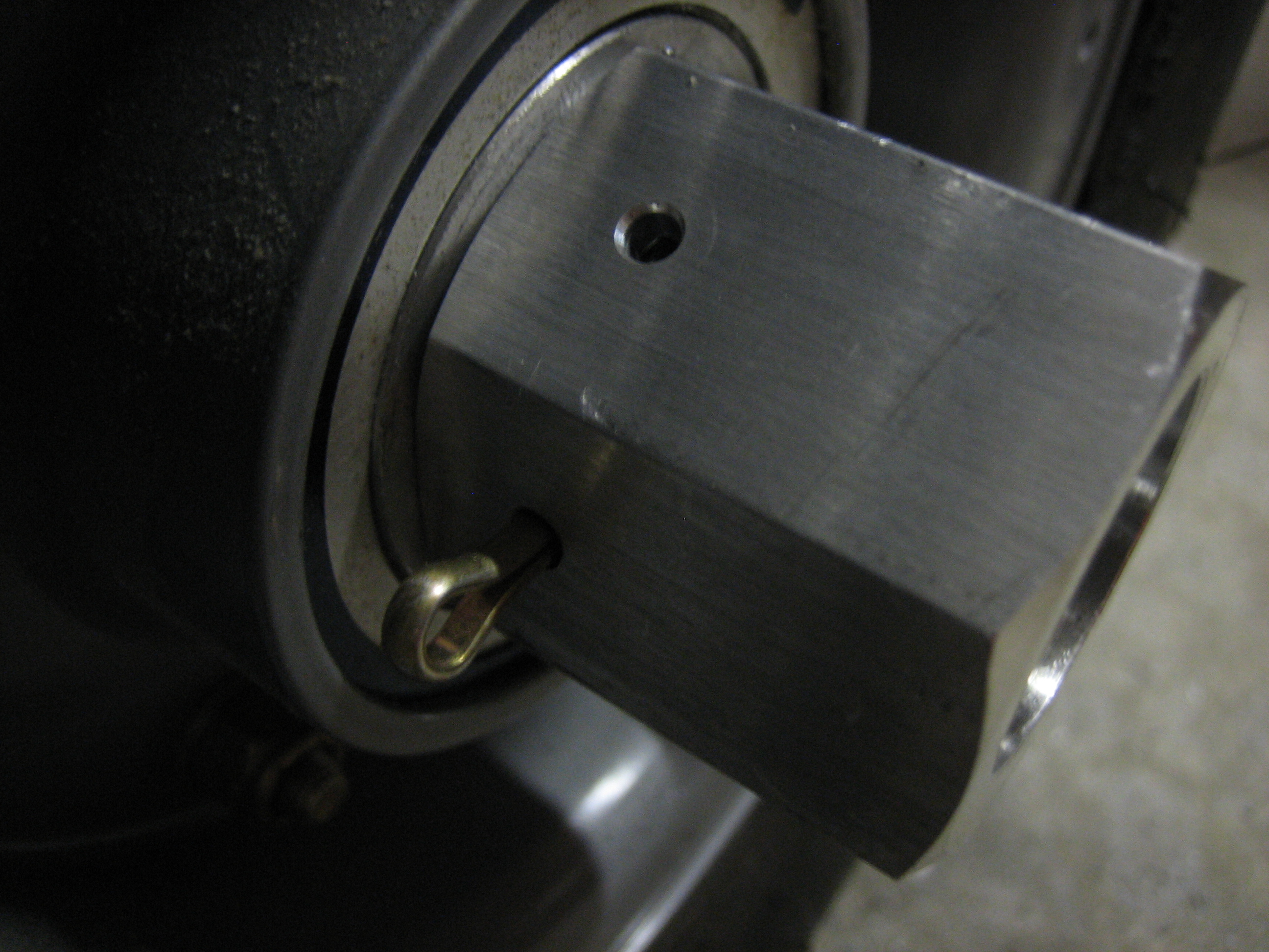
While the nut was on the axle, I marked where the bracket will sit so that it will be level with the ground when installed. That way, the screws that attach the bracket will be easier to reach.
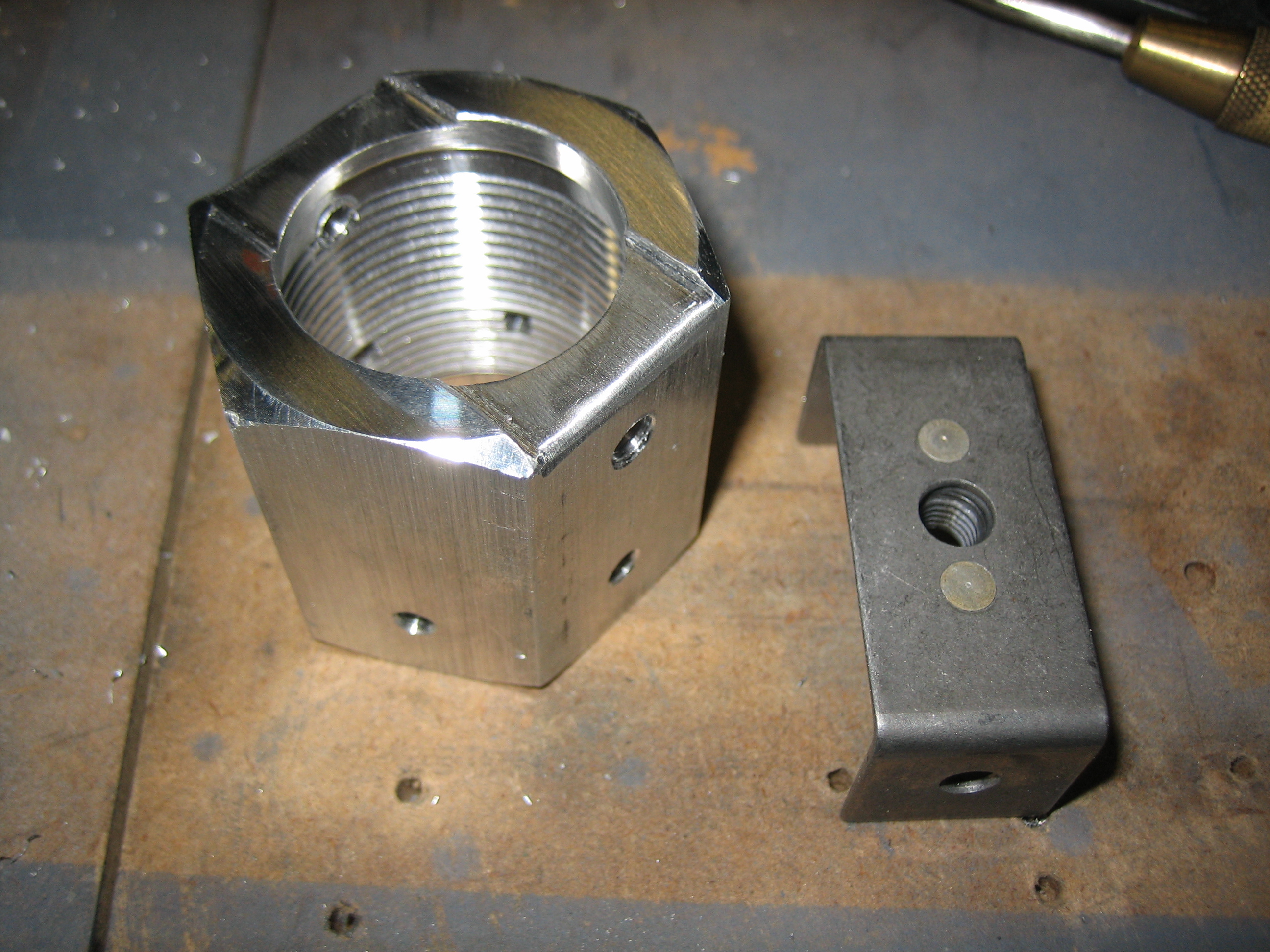
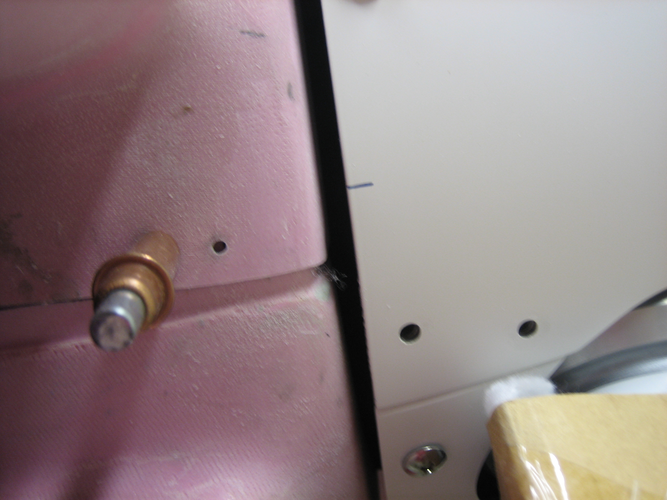
Modified Left Axle Nut
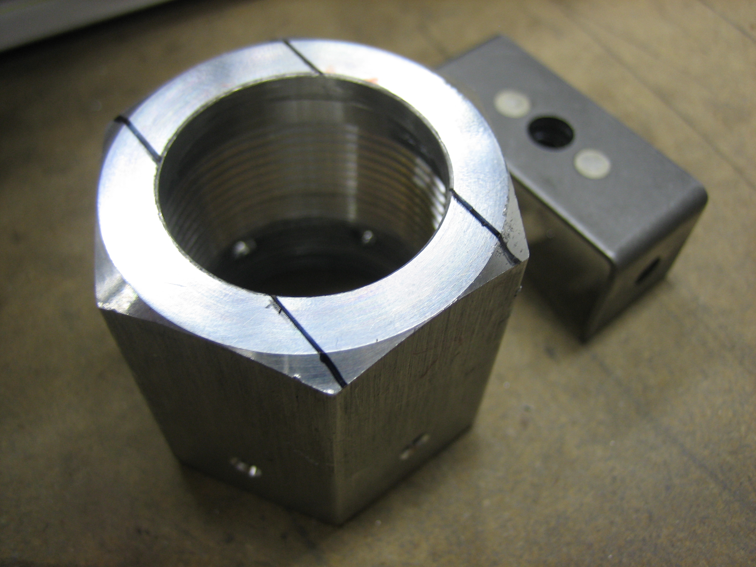
I cut the recess in the left axle nut so that the bracket will sit flush with the outside end of the nut, then drilled and tapped the sides for the 10-32 screws.
Afterward, I cleaned the AeroShell 33MS grease out of my bearing packer so that I could replace it with AeroShell 22 since I decided to switch my wheel bearings to that after doing some more research. I’m still going to use AeroShell 33MS everywhere else on the plane. Cleaning a bearing packer is a real pain in the ass. It would probably have been easier to just buy a new bearing packer.
Repacked Left Wheel Bearing and Started Right Axle
I removed the bearings from the left wheel and completely cleaned the old AeroShell 33MS grease out and then repacked them with AeroShell 22. I then reassembled everything and reinstalled the wheel and axle nut. I installed the cotter pin, but haven’t bent it over yet. I’ll leave it straight until I know for sure that I don’t need to remove the wheel before the first flight.
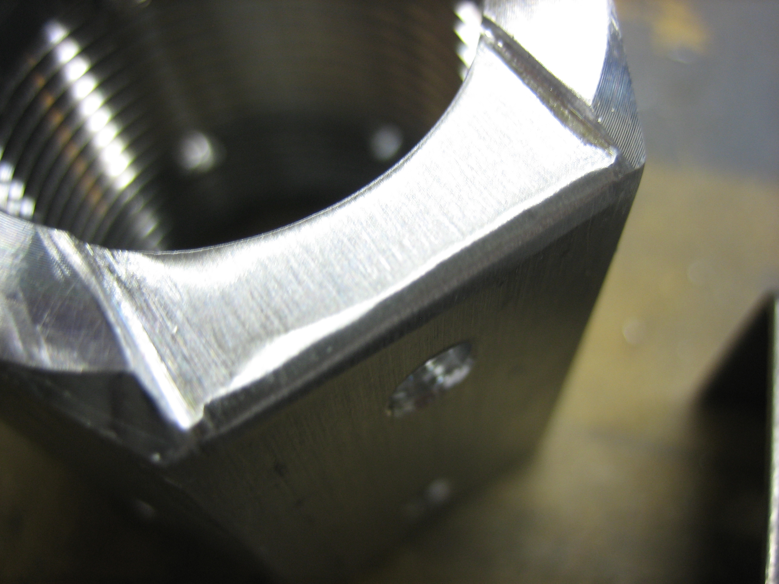
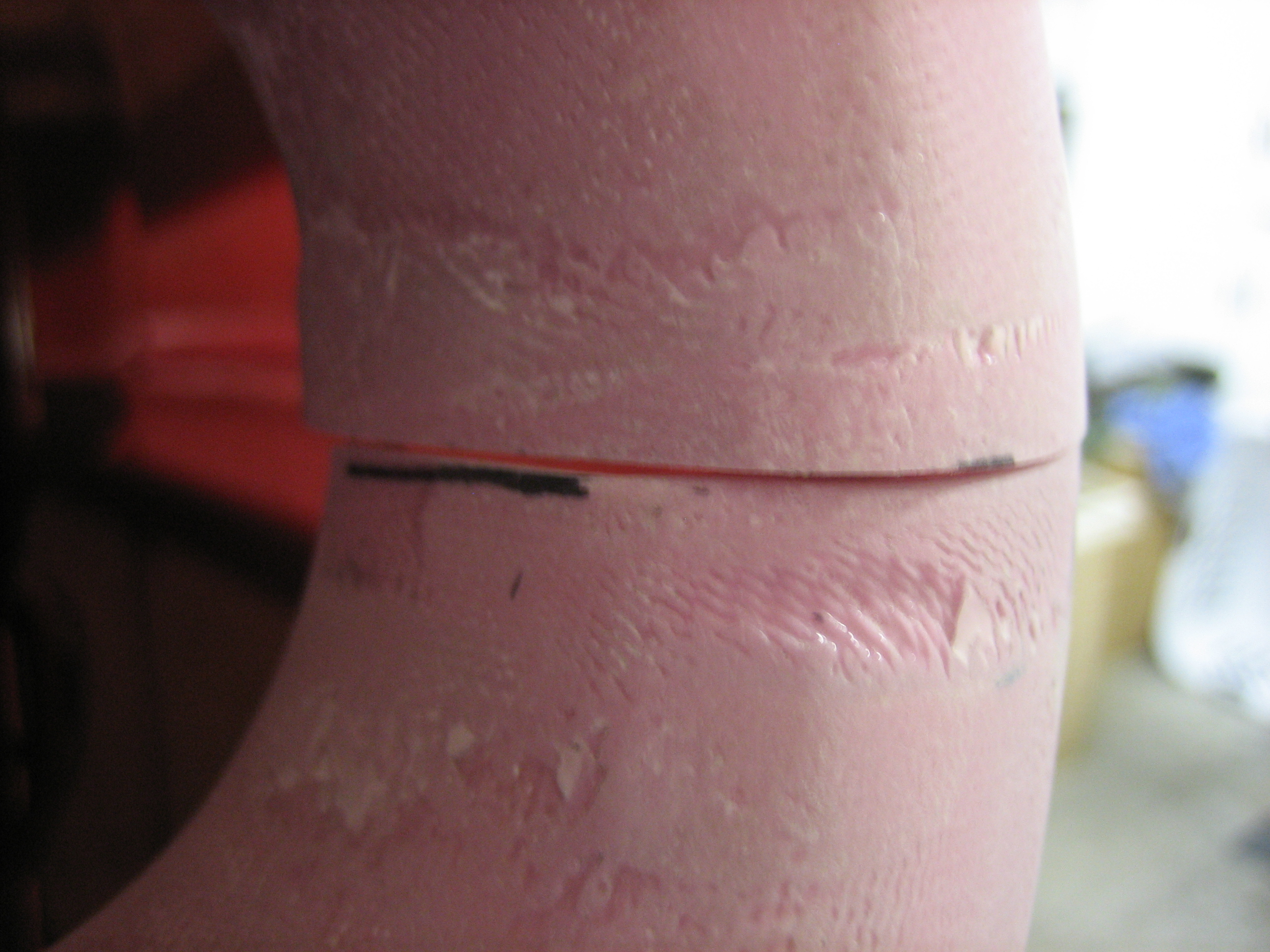
With the left wheel done, I jacked up the right side of the plane and drilled the right gear leg. I then modified the right axle nut for the wheel pant bracket.
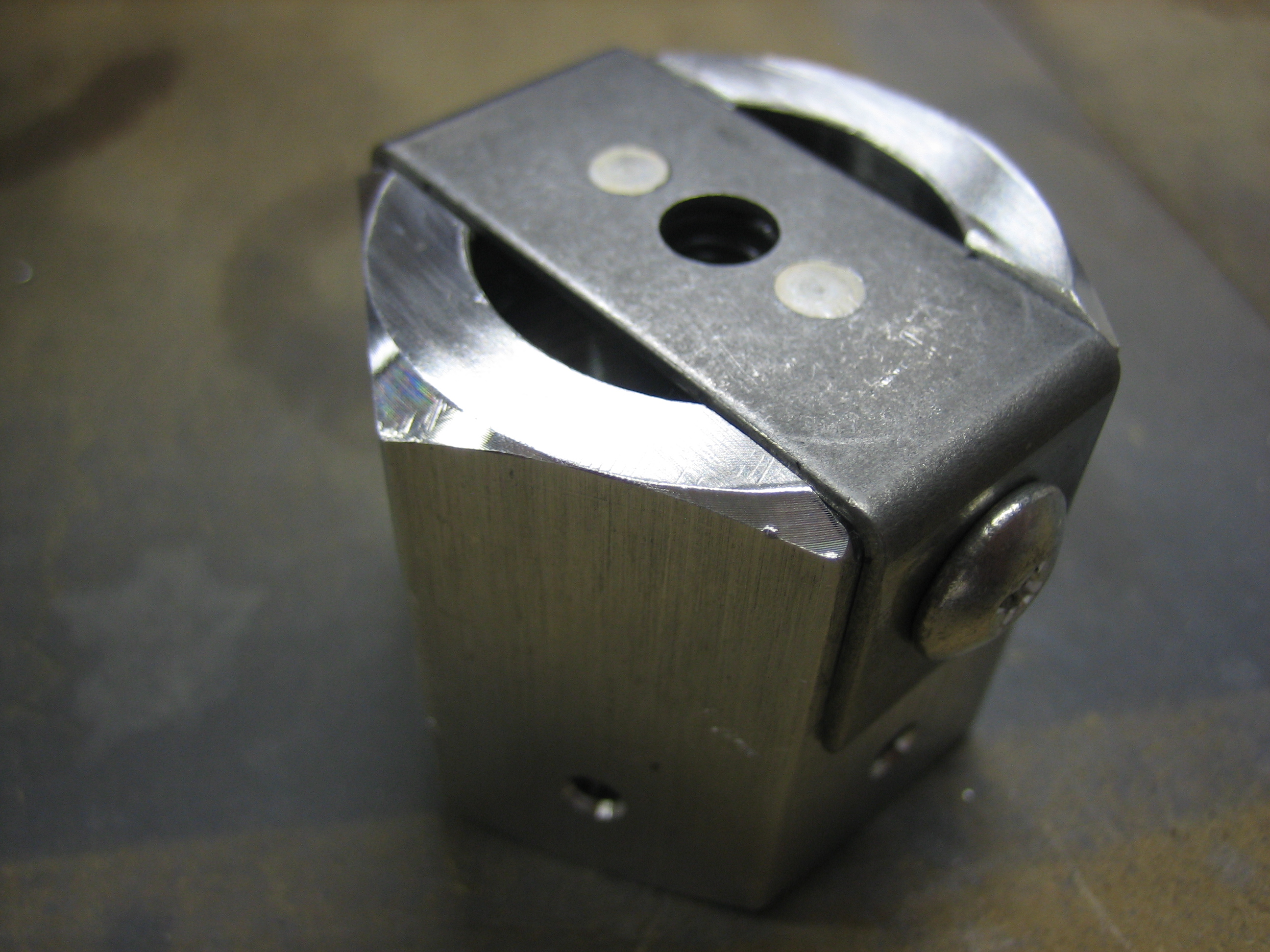
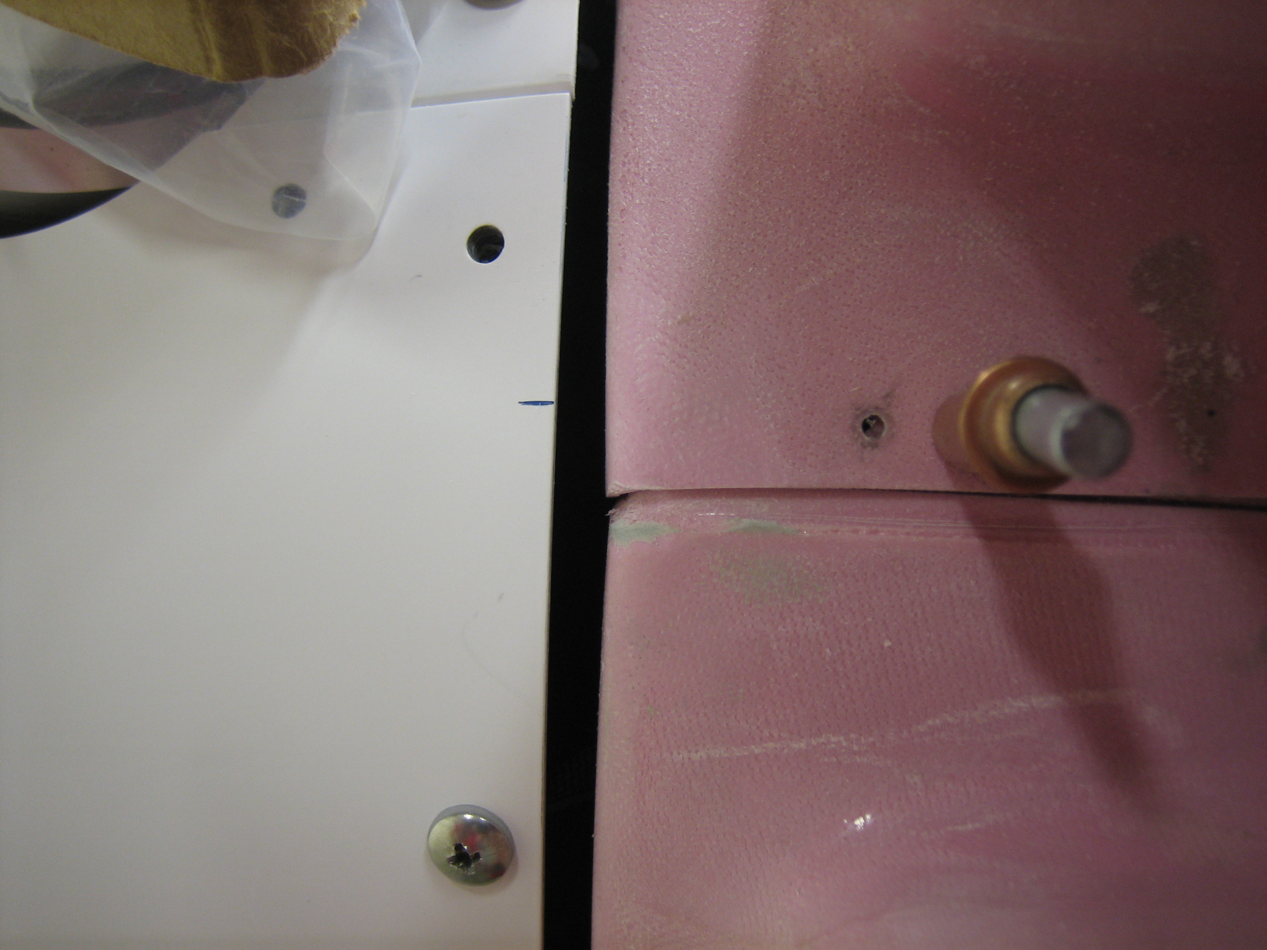
Here’s a closeup of the notch that you have to file into the axle nut. You can see that you have to radius the edge because of the bend in the bracket. This took about 15 minutes of filing to get to this point.
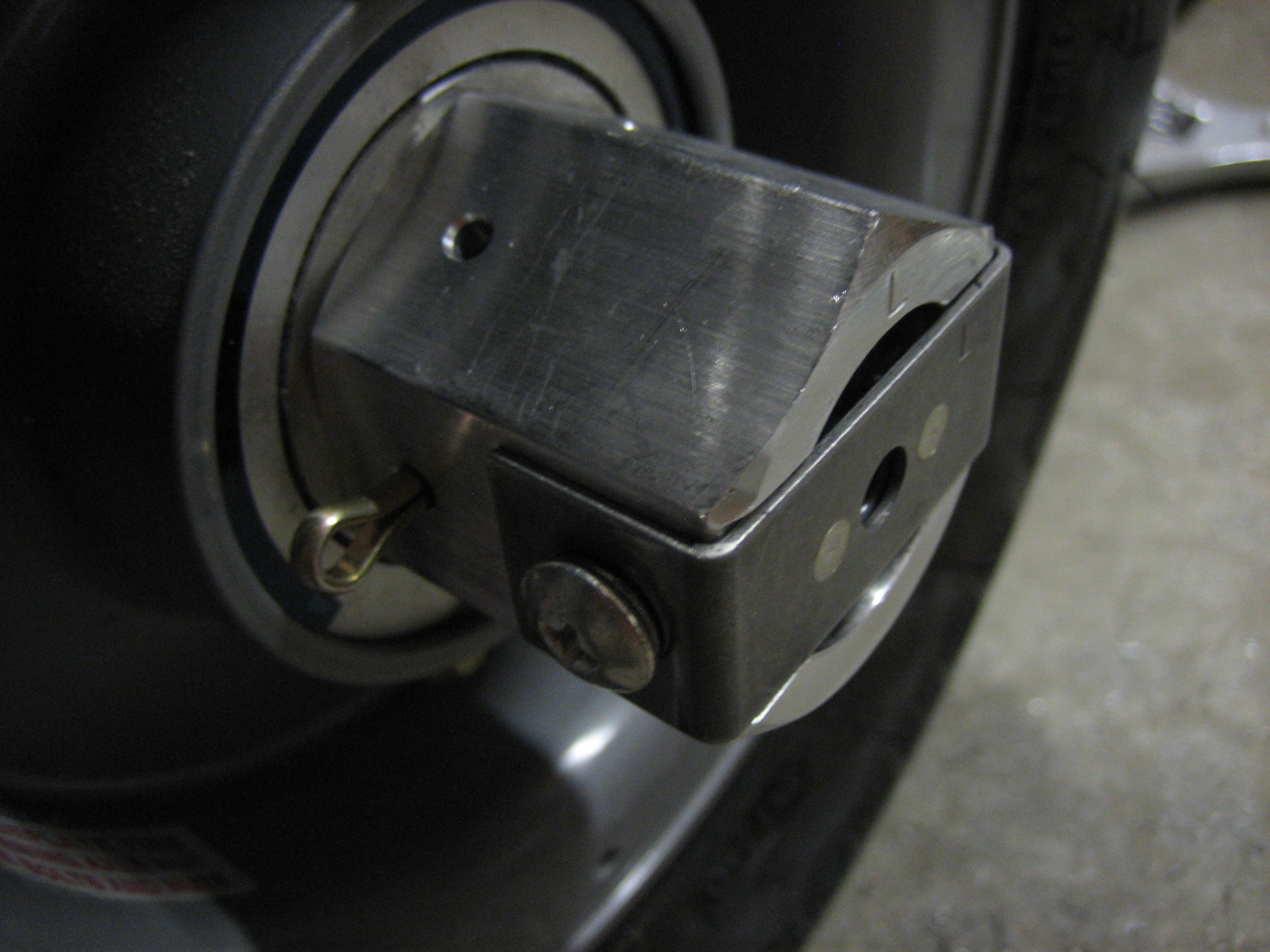
Finished Right Axle
I repacked the right wheel bearing and reinstalled the right wheel. Other than possibly fitting the wheel pants, I probably won’t need to touch the wheels again before first flight.
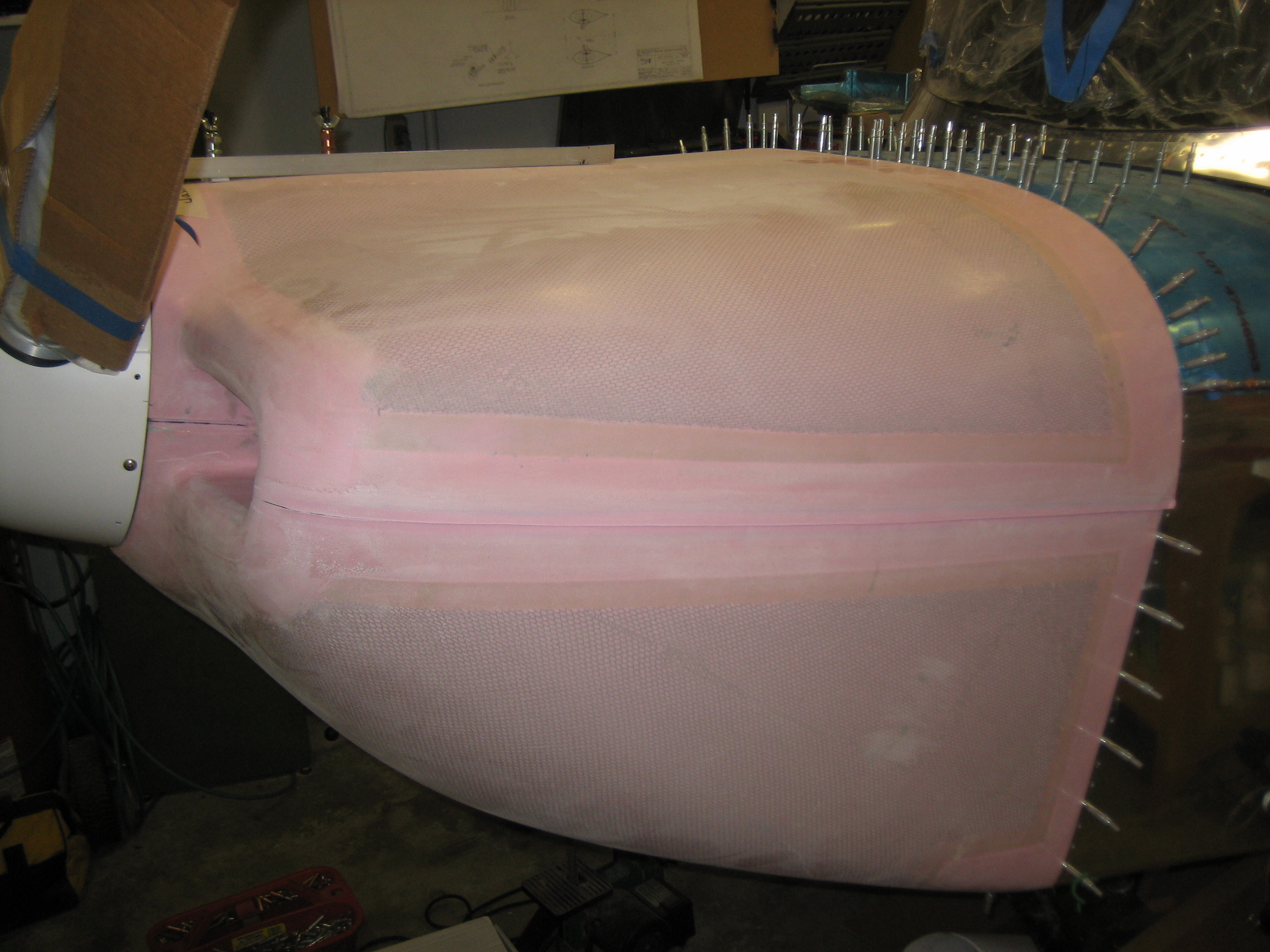
Got Cowl Back
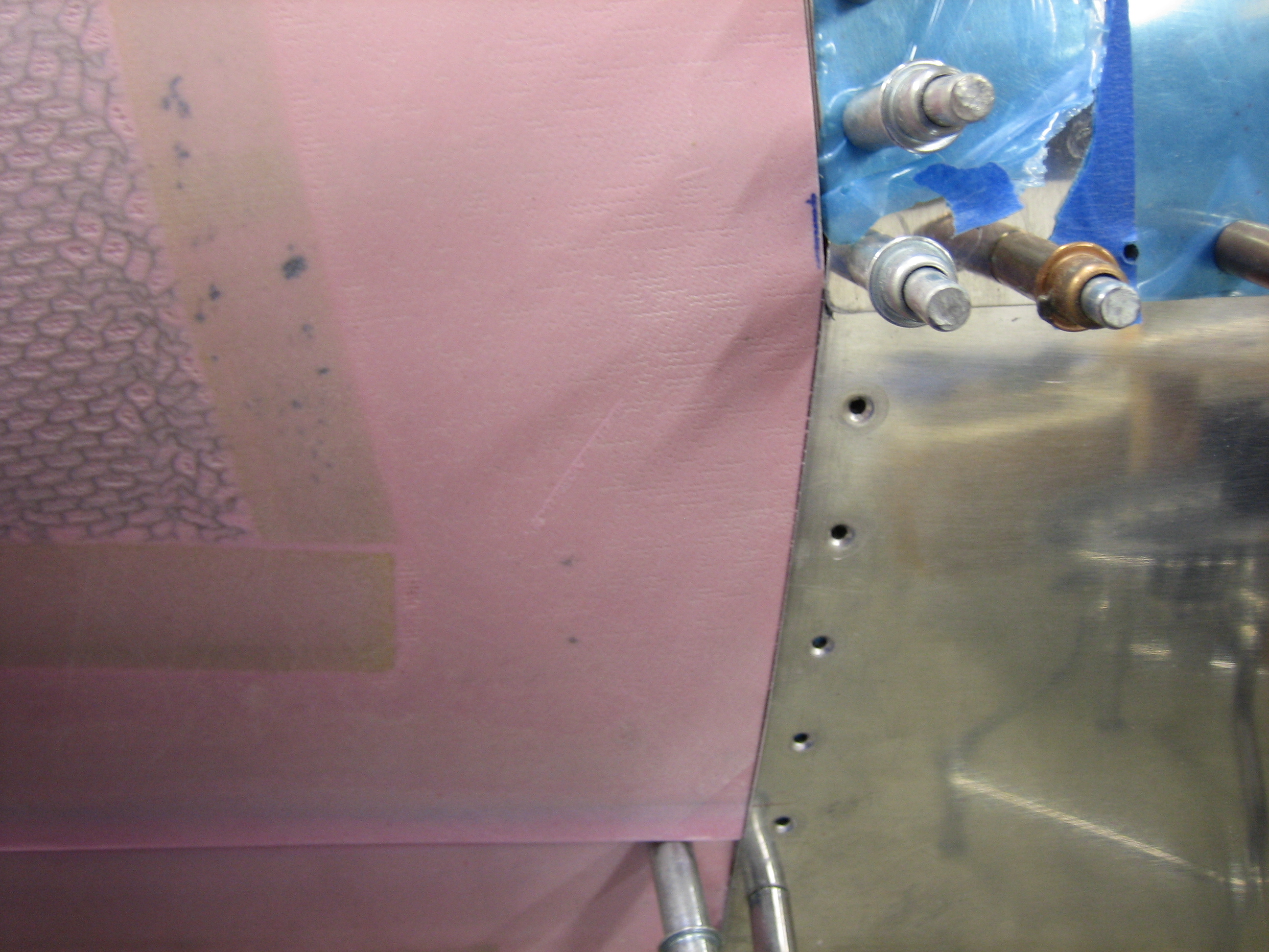
I got my cowl back from M&W Composites today. They repaired their manufacturing error by glassing some additional material onto each edge (between 1/8″ and 1/4″) and putting it back in their oven to cure. I unpacked it and did a trial fit. Things look much better already. Without even pulling things down tightly, the sides already overlap a little bit. Here’s a pictures of the left side.
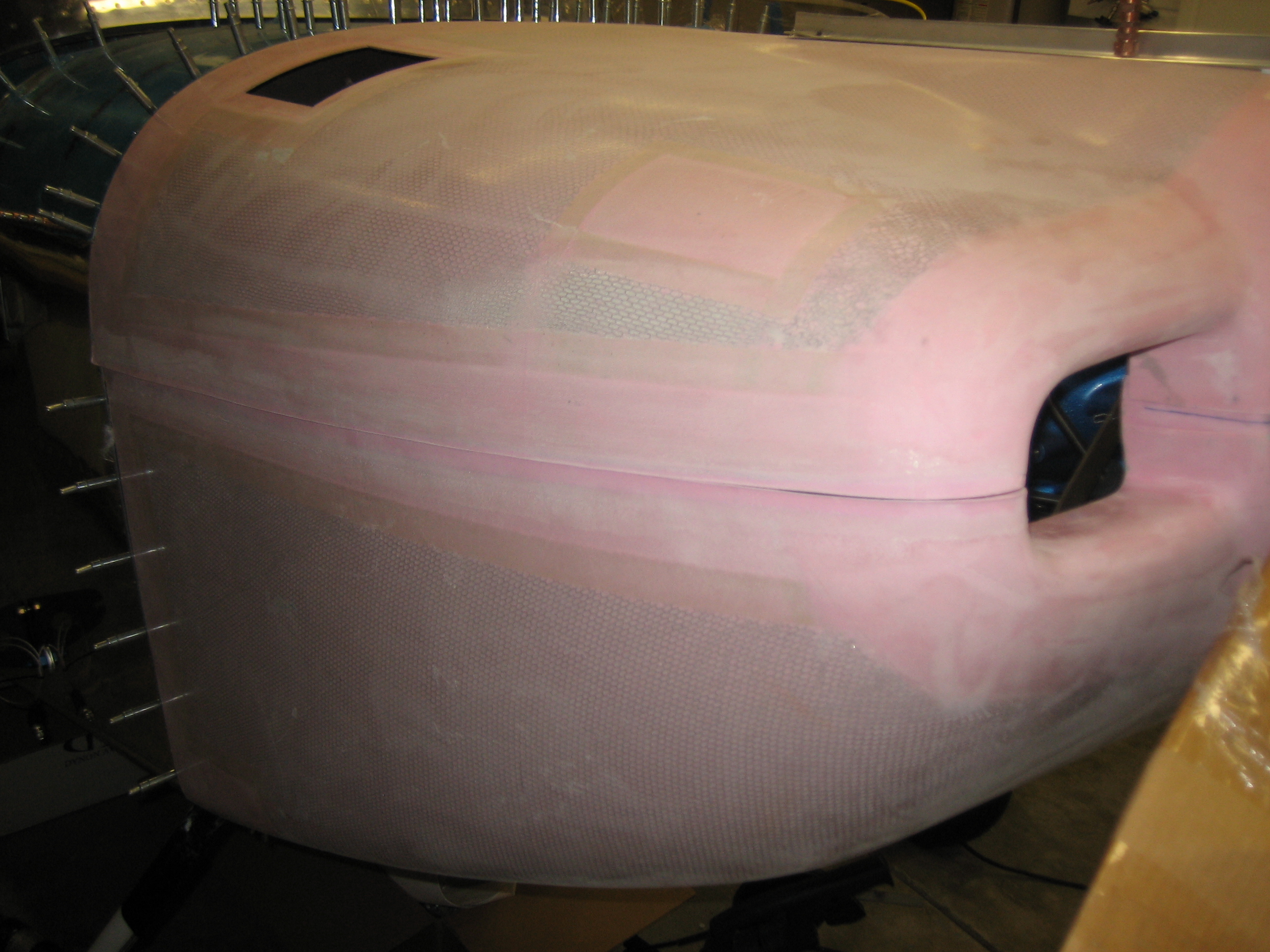
And the right. I need to do a little further trimming around the front inlets before I can pull the spinner opening back to where it was.
Continued Work on Cowl Joint
I sanded a couple of the joints to get the front a little tighter. There’s no way everything will align perfectly even once all the trims are complete. I’ll end up covering all this with micro and sanding everything totally smooth around these joints.
I also trimmed the remaining ears off of the upper cowl. I still have some sanding to do to get this perfect, but this at least allows the top cowl to tuck down a little further.
Interior Arrived
My Classic Aero Designs interior showed up today. Here is one of the seat backs and bottoms. My tail number (N4VR) is embroidered in the horizontal stripe. The wires coming out of each piece are for the seat heaters.
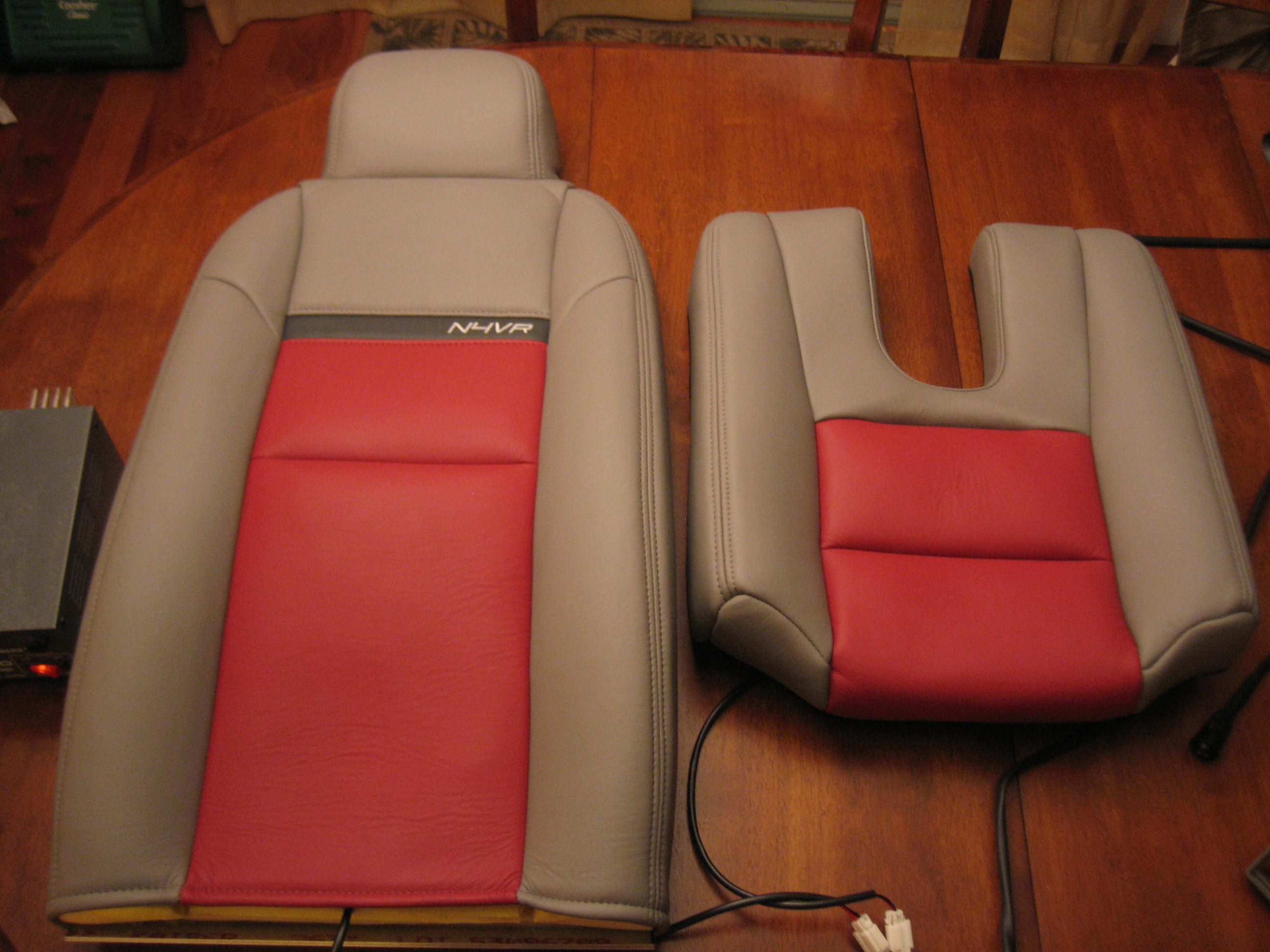
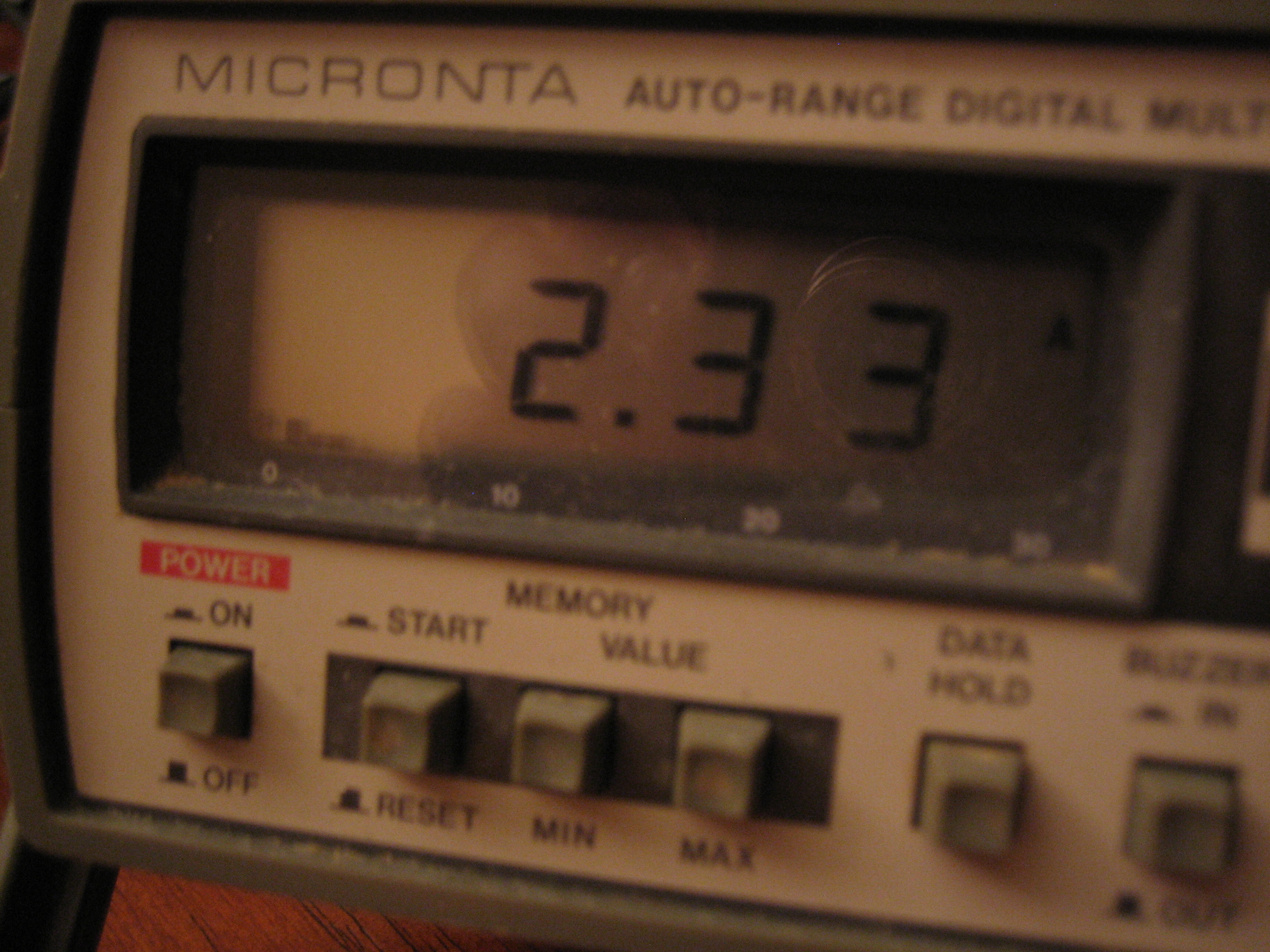
I hooked up a power supply to see how much current the seat heaters draw.
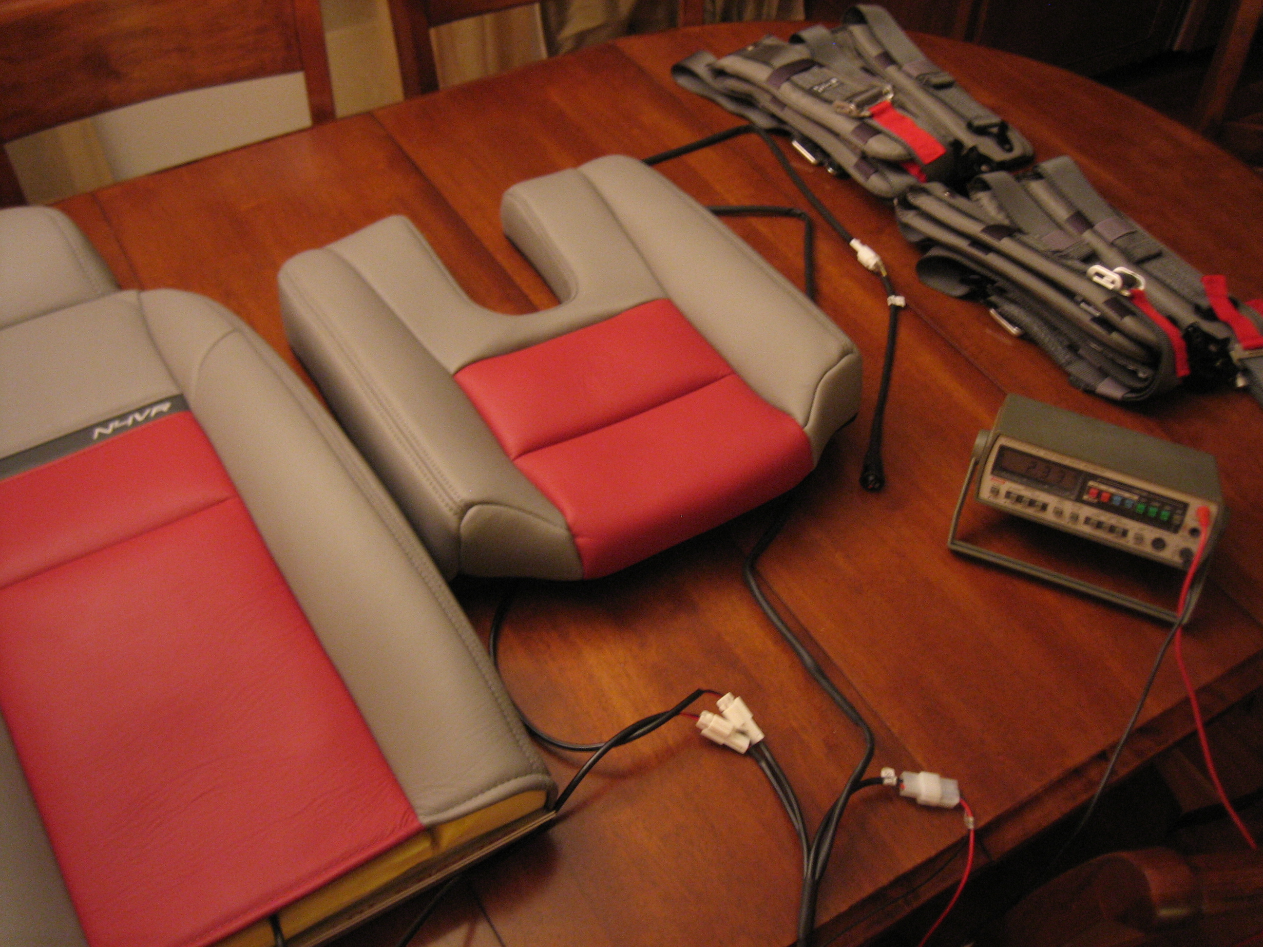
I was pleasantly surprised to see that they drew much less than I anticipated. The website says that they draw about 5A per seat on high, but I’m seeing less than half that. On low, they only pull about 0.7A per seat.
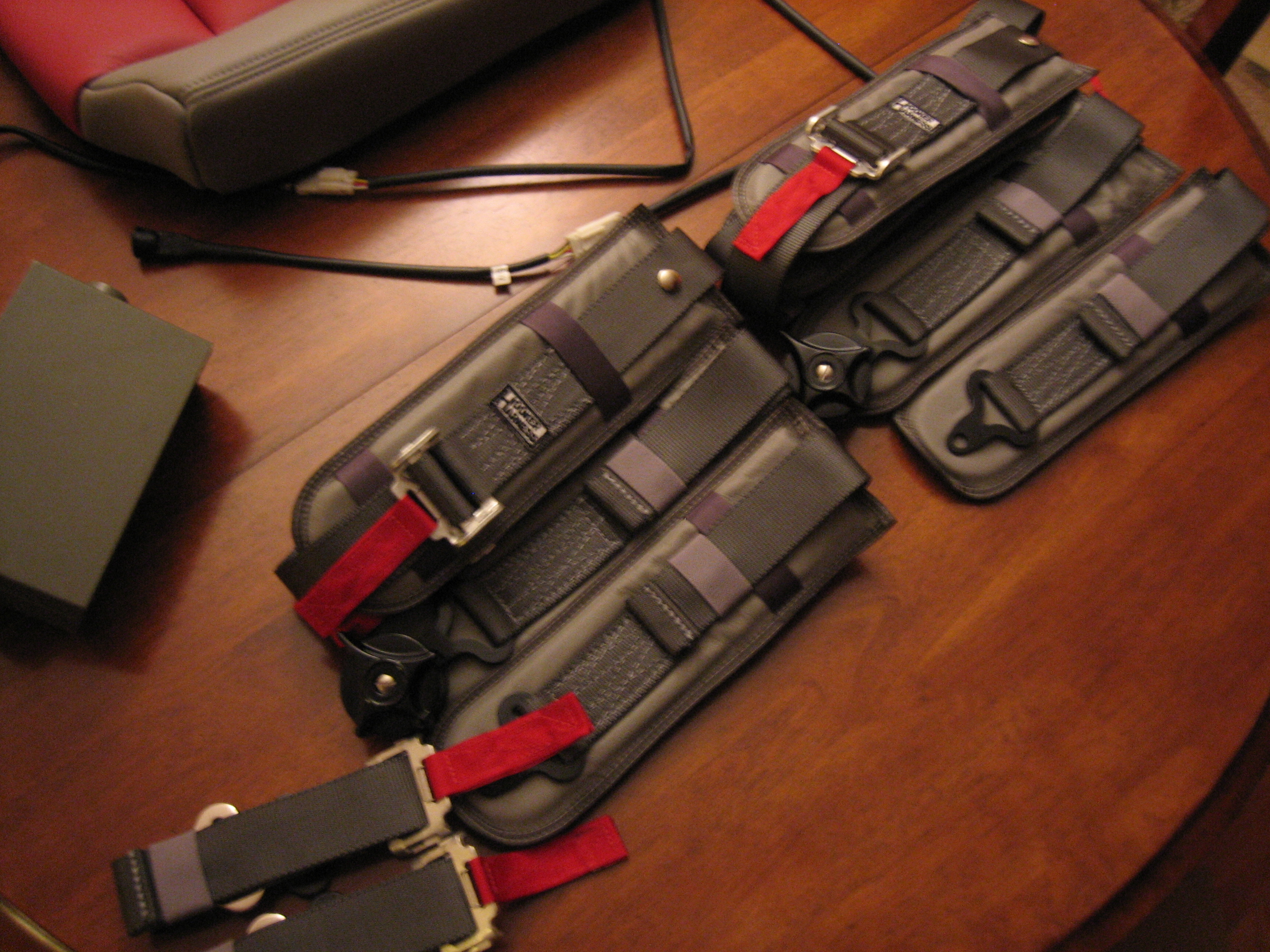
My Hooker Harness harnesses also arrived. I had Classic Aero make the pads out of the same leather used on the seats with some red pull tabs to go with the other red accents in the cockpit.
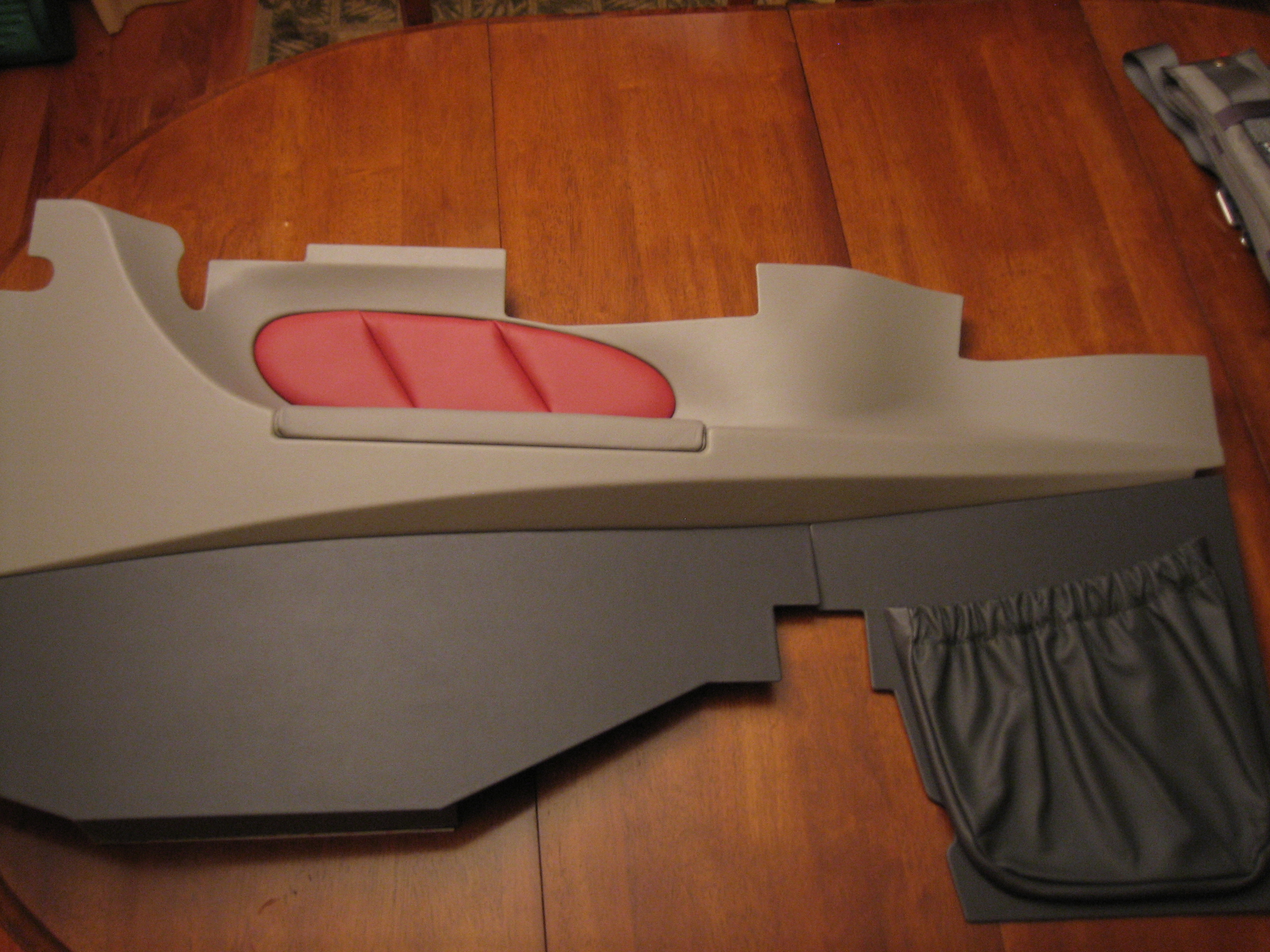
Here are some of the side pieces. There covered in vinyl with a leather armrest, side pad, and pocket.
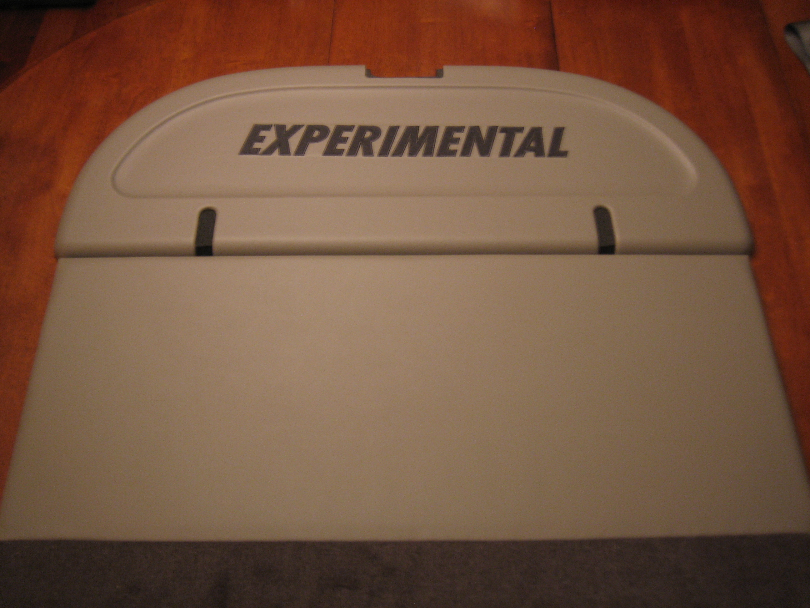
Here are the pieces that cover the back wall. In addition to these pieces, there are pieces that cover the baggage side walls and carpet for the forward floor, seating and baggage areas.
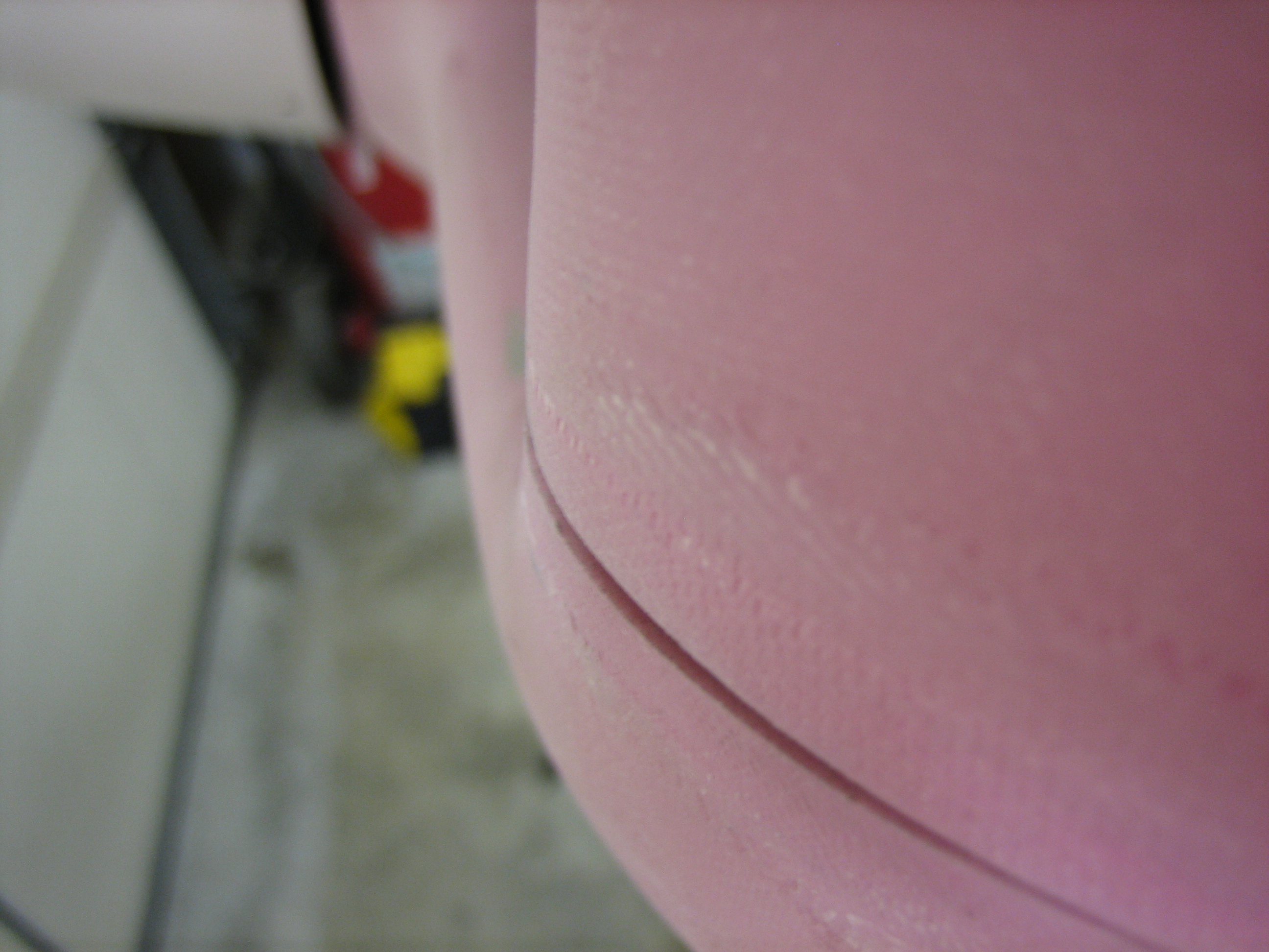
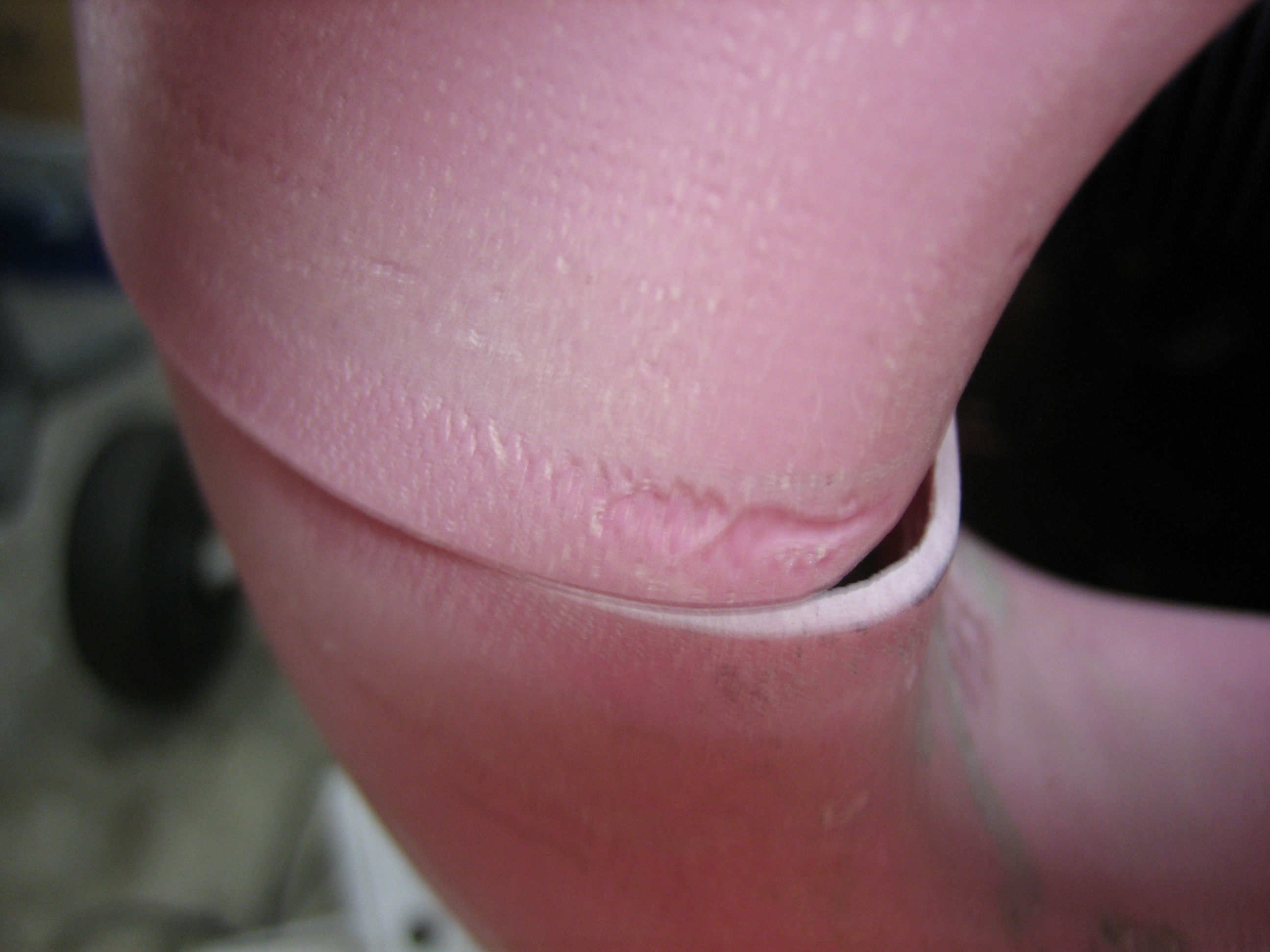
Fixed Spinner Gap
One thing that has been bugging me about the fit between the upper and lower cowl halves is the fit between the cowl and the spinner. If you go back and look at this entry, you can see what I’m talking about. Because any further work will lock in the fit between the upper and lower halves, I needed to take care of this now. I cleaned up a few boogers inside the flange of the upper cowl and then ground away a fair amount of the face of the lower flange to allow the upper cowl to slide backward over 1/16″. Now the gap is really nice all the way around the spinner. I’ll probably still add a little filler to make the gap perfect, but I want to have the two cowl halves completely trimmed and joined along the sides. Here’s the fit on the right side.
Worked on Lower Cowl
I did a little minor sanding on the fit between the lower cowl and the firewall flange and then finished sanding the horizontal joint in the lower cowl until it is perfectly straight on both sides. I think the lower cowl is pretty close to how I want it now. I will still need to do some adjustment around the inlets, but that can wait until the top and bottom halves are mated so that I can do it off the plane.
I hear so many builders complain that they hate working with fiberglass, but I’m really digging it. There is a certain freedom that comes with knowing that you can repair almost anything. If a part is too long, trim it. If it’s too short, add back some material. If two parts don’t align, you can reshape it easily. Done properly, any repairs can be just as strong as the rest of the material.