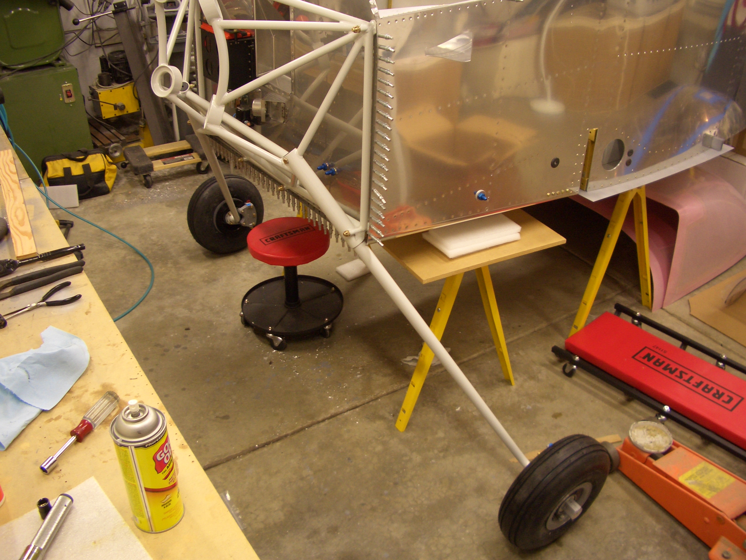
Andre stopped by today and helped me fit the engine mount and main gear. I used a couple of long Bessey clamps to clamp from the vertical side tubes of the mount to the center section. I then used a dead blow mallet to adjust the mount until it was evenly spaced all around, then tightened the clamps to prevent the mount from moving. I used a 3/8″ drill bit and drilled the holes in the firewall. There are six holes in total, and all pass through beefy structure on the backside of the firewall to transmit the engine loads into the rest of the airframe.
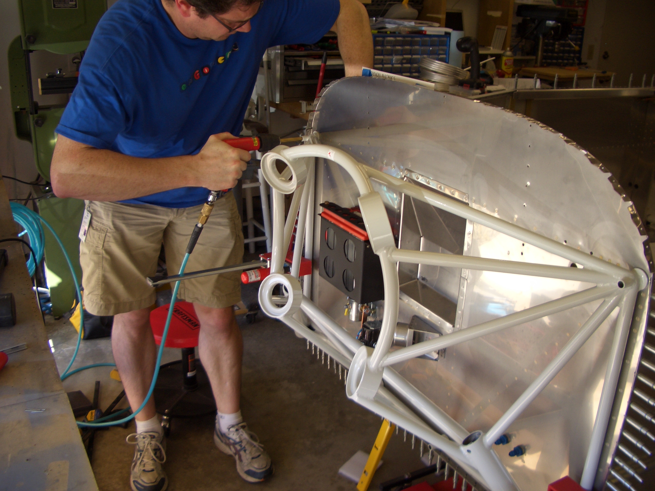
Here is the engine mount all drilled with four of the bolts installed temporarily. Now that the mount is in place, I marked where the gear legs will interfere with the lower firewall flange. I used a carbide burr in my die grinder and removed the material that was visible through the landing gear tube.
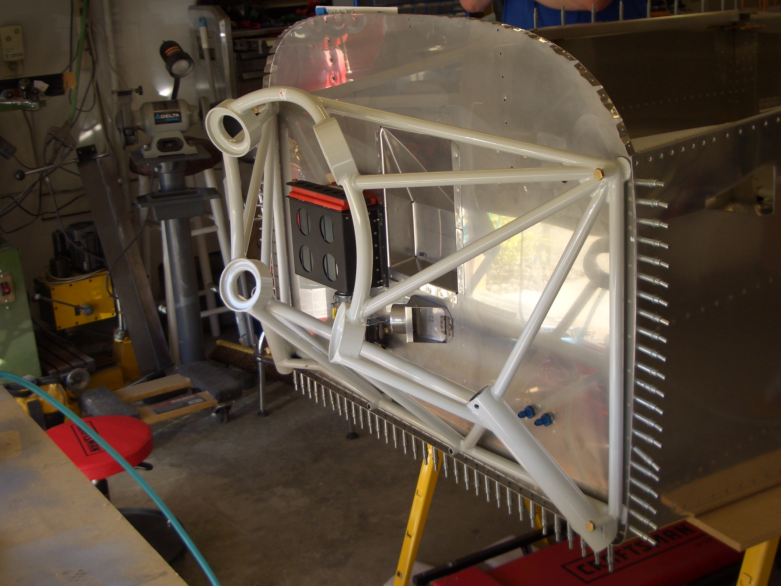
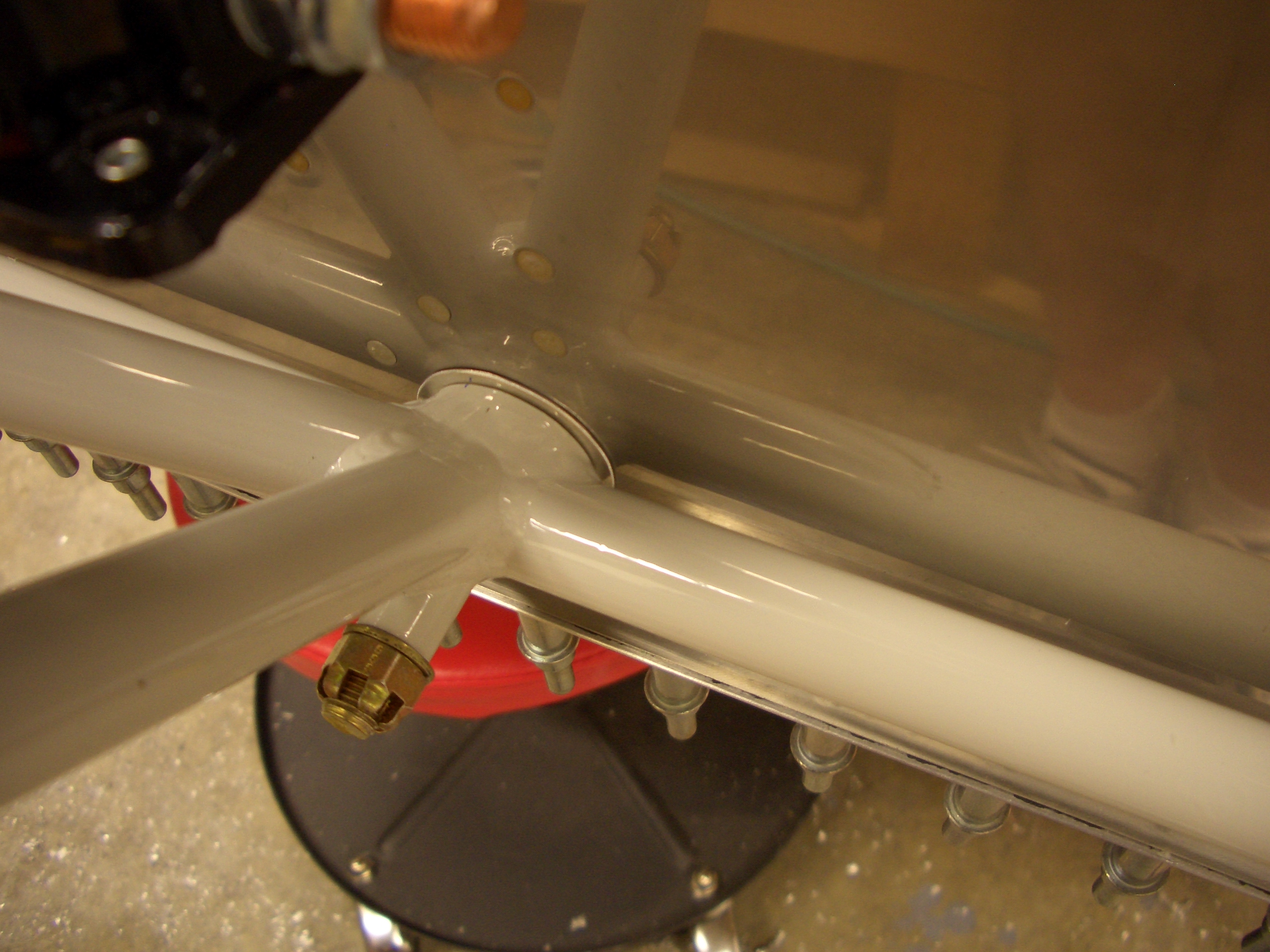
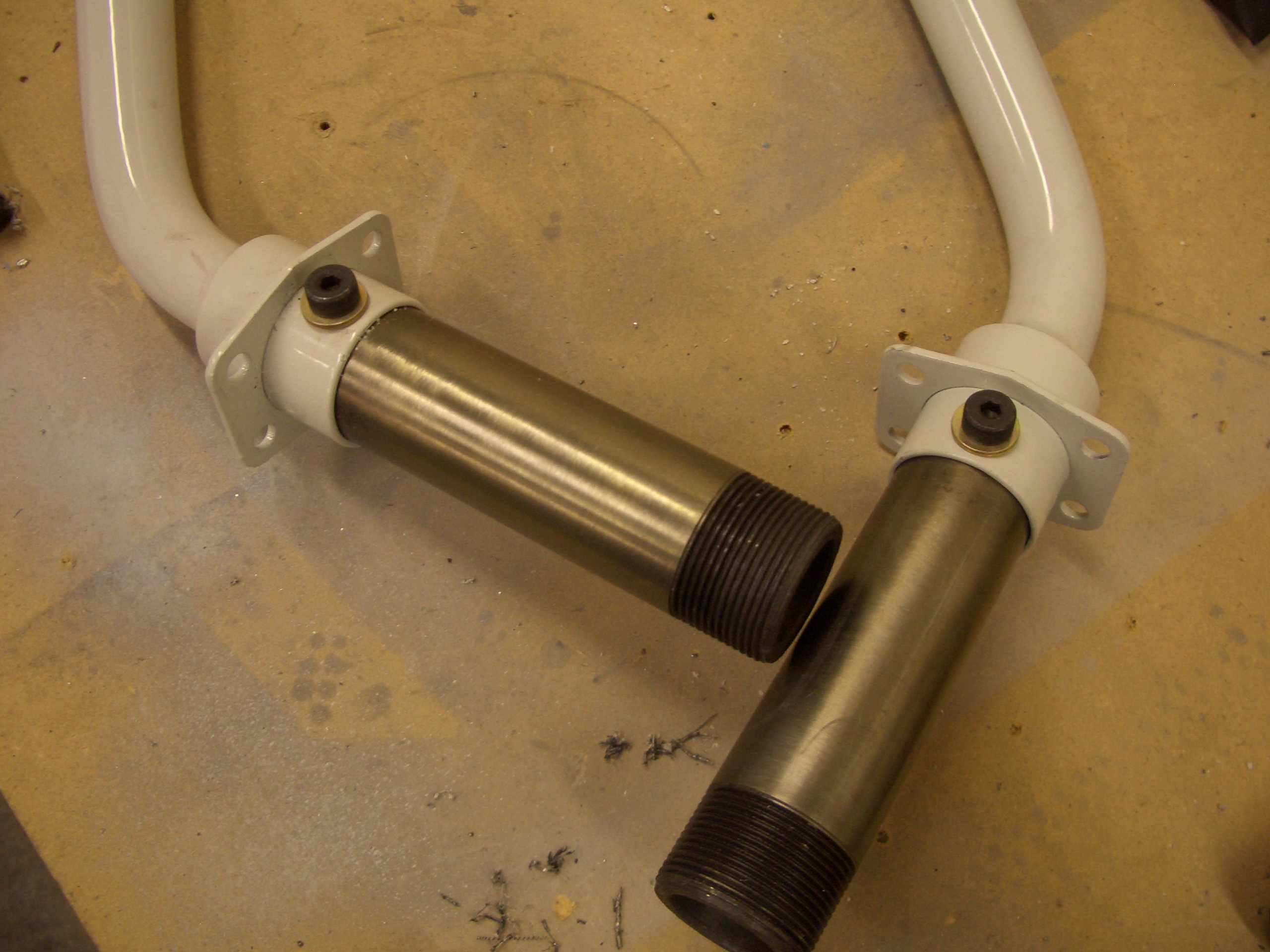
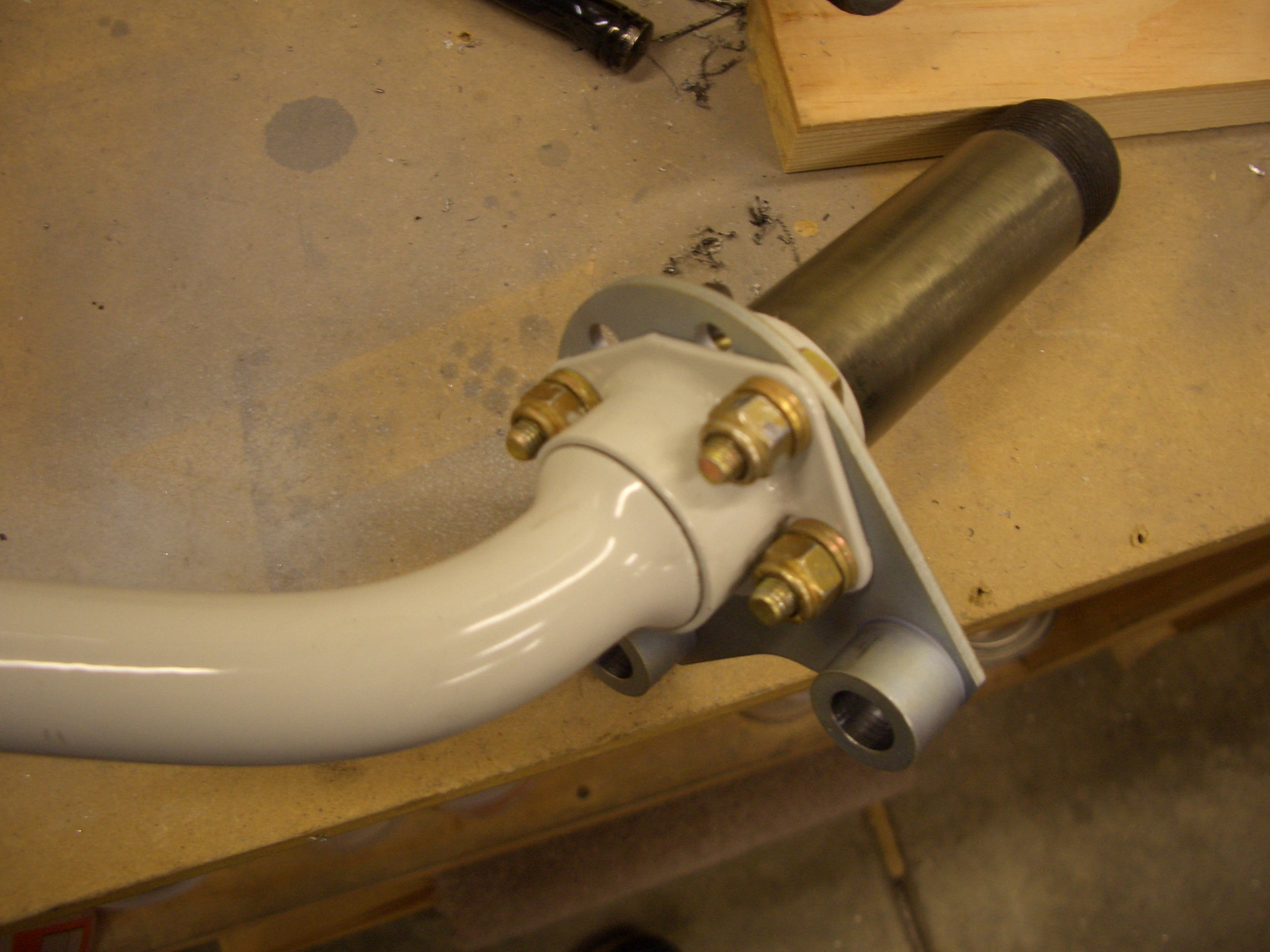
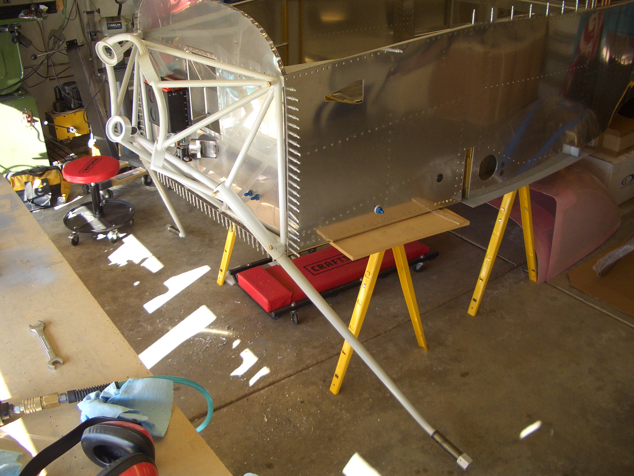
I slipped the landing gear in the mount and with a little muscling, I got them all the way in so that I could slip an AN5 bolt part way into the hole at the top. The gear legs have bearing surfaces inside that only touch the engine mount at the top of bottom of the outer tube. There is a single bolt at the top of the tube that holds the gear legs on. It doesn’t seem like much, but I’ve never heard of one of these failing, so it must be plenty strong.
The flanges for the two center holes in the engine mount don’t touch the firewall. This is a pretty common problem since the engine mount can distort slightly during welding. The fix is simple and requires fabricating little spacers so that the bolts can be tightened without flexing the mount. These are pretty thin (0.016″ and 0.032″). I took the mount off, deburred the holes and cleaned up the shavings. I reinstalled the mount with the proper hardware, but then realized that I don’t have an appropriate torque wrench for these bolts. These need to be tightened to 160-190 in-lbs, but my smaller torque wrench only goes to 150 in-lbs and my bigger one starts at 20 ft-lbs (240 in-lbs). I’ll probably use an extension on my smaller torque wrench instead of buying an intermediate torque wrench since these are the only AN6 bolts on the airplane. My current torque wrenches can torque AN5 (and smaller) as well as AN7 (and larger) bolts.