Random Fuselage Tasks

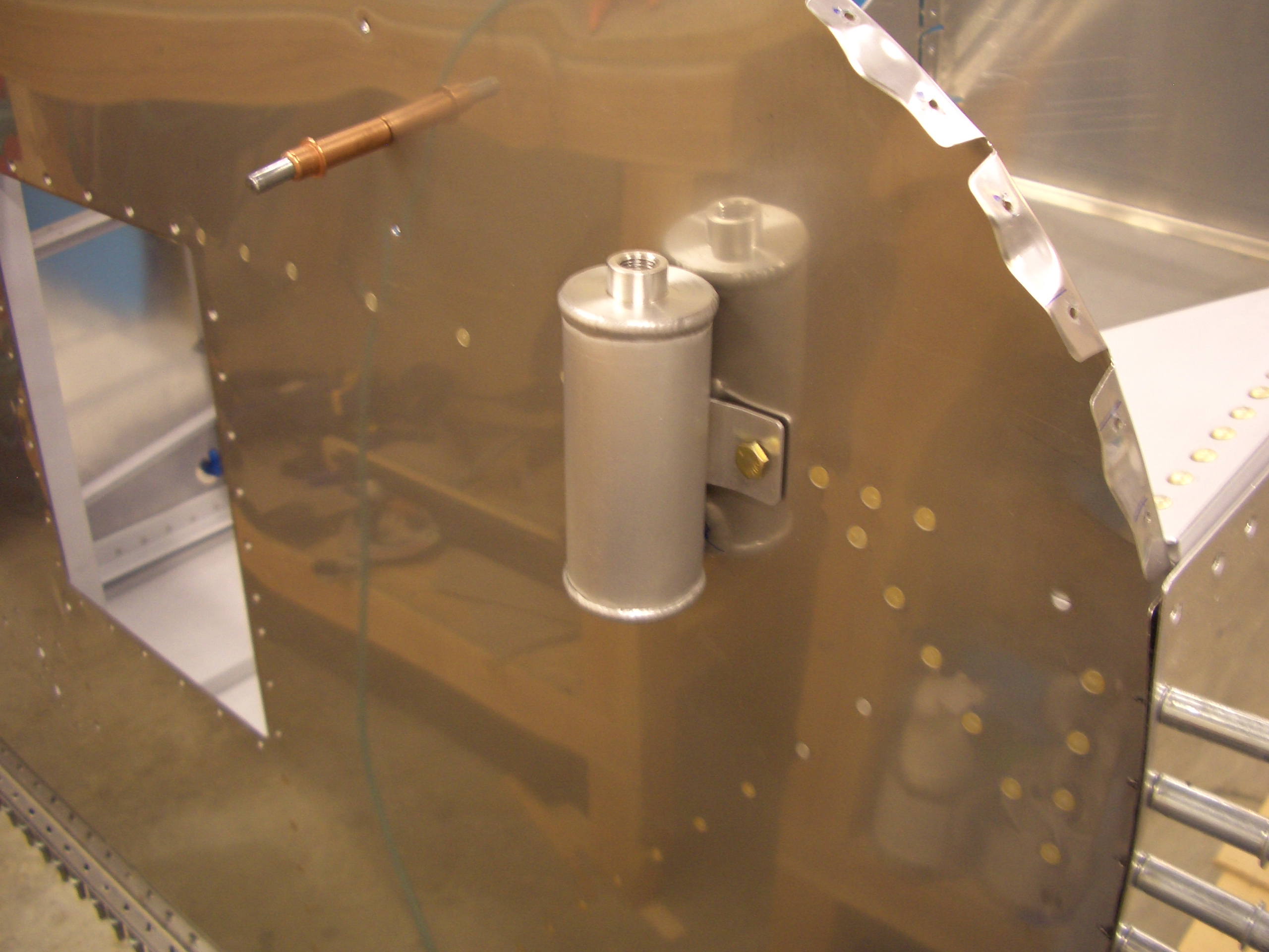
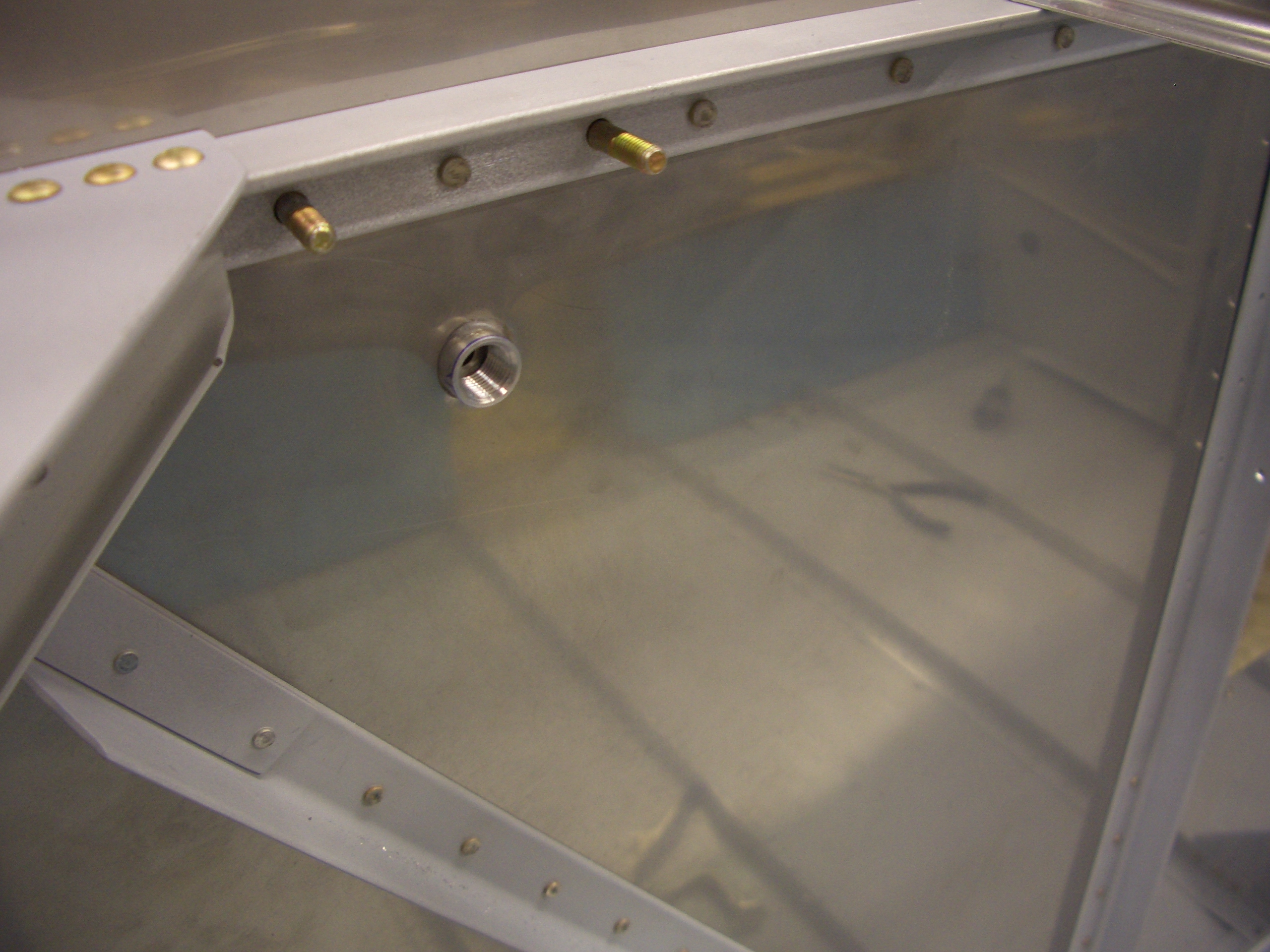
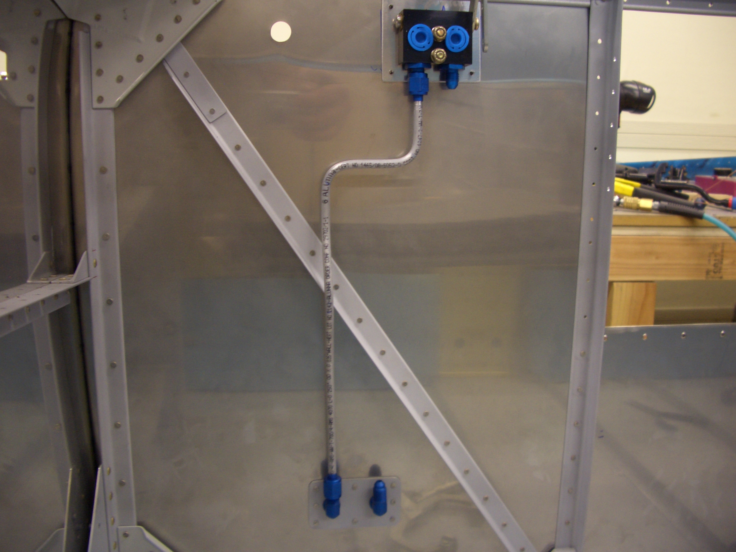
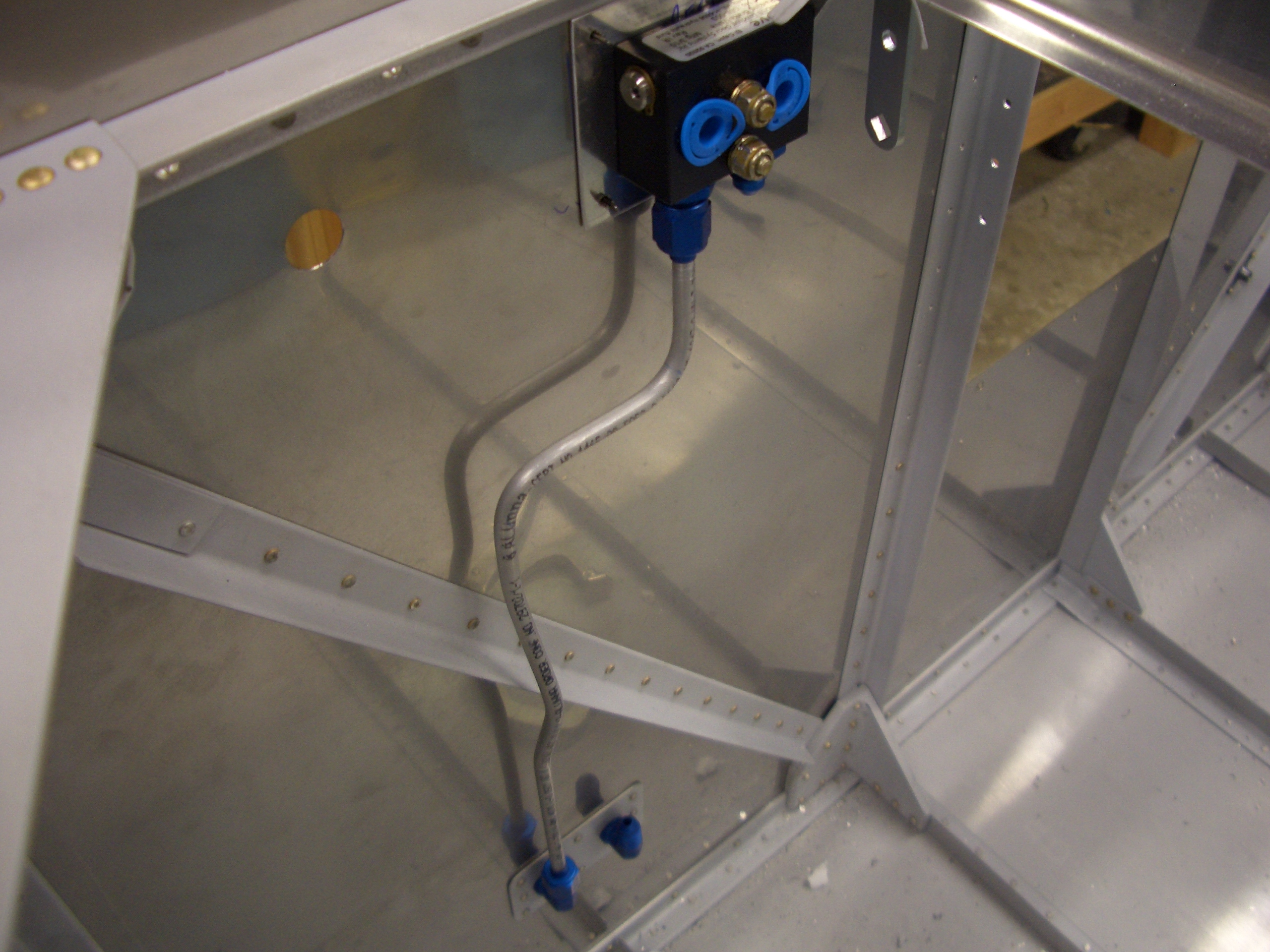
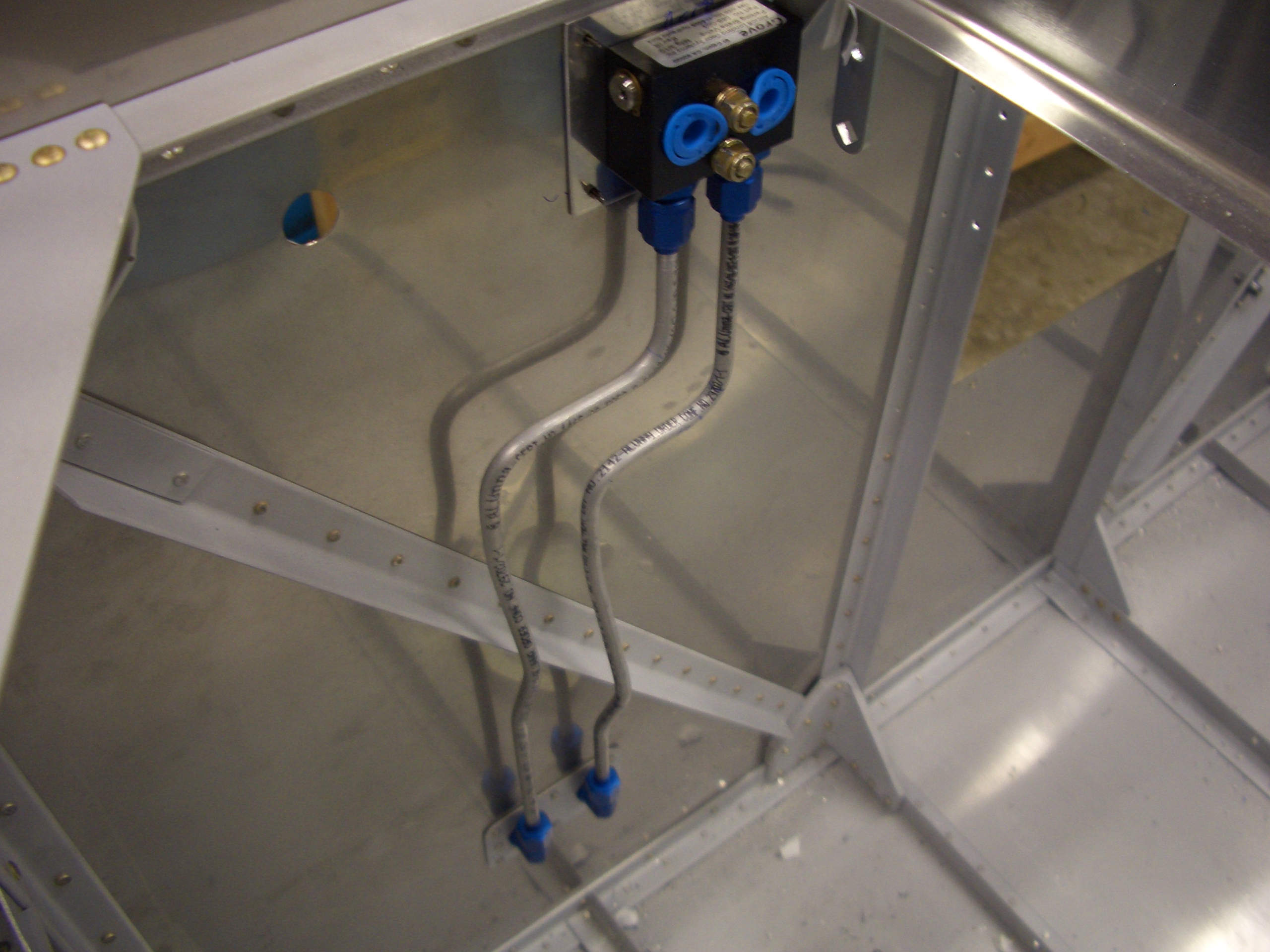
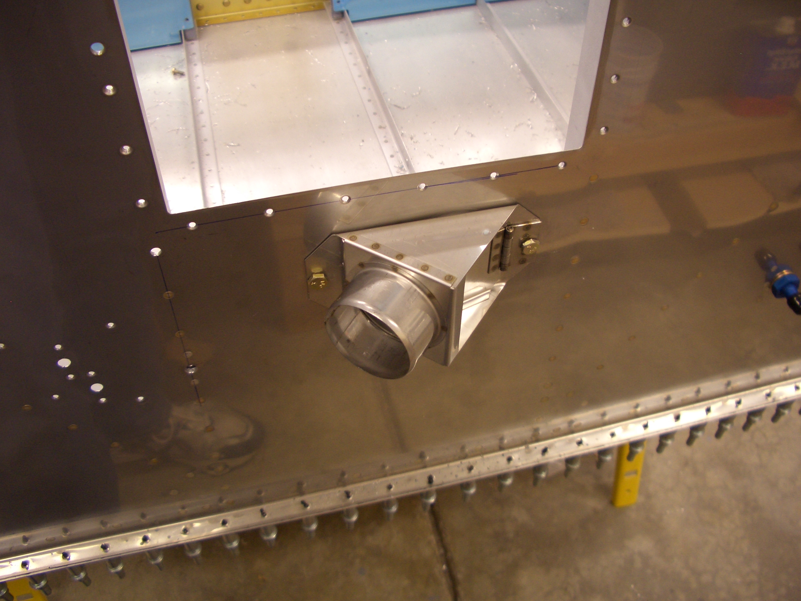
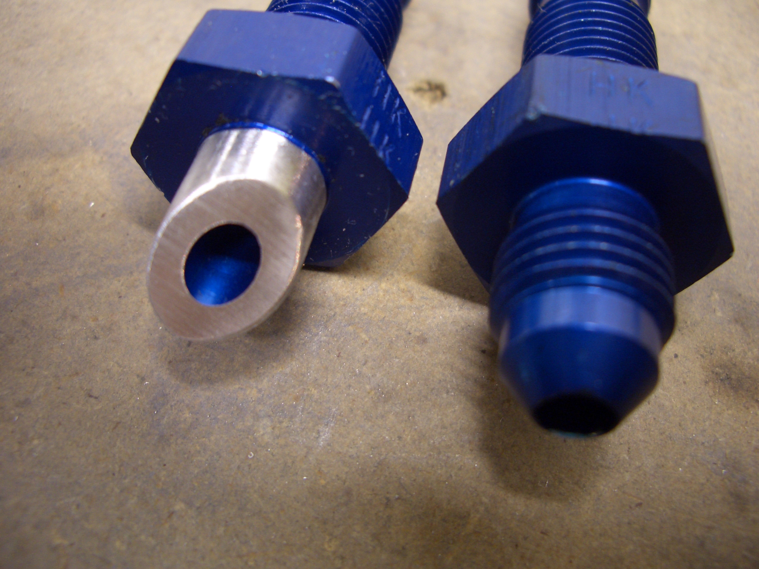
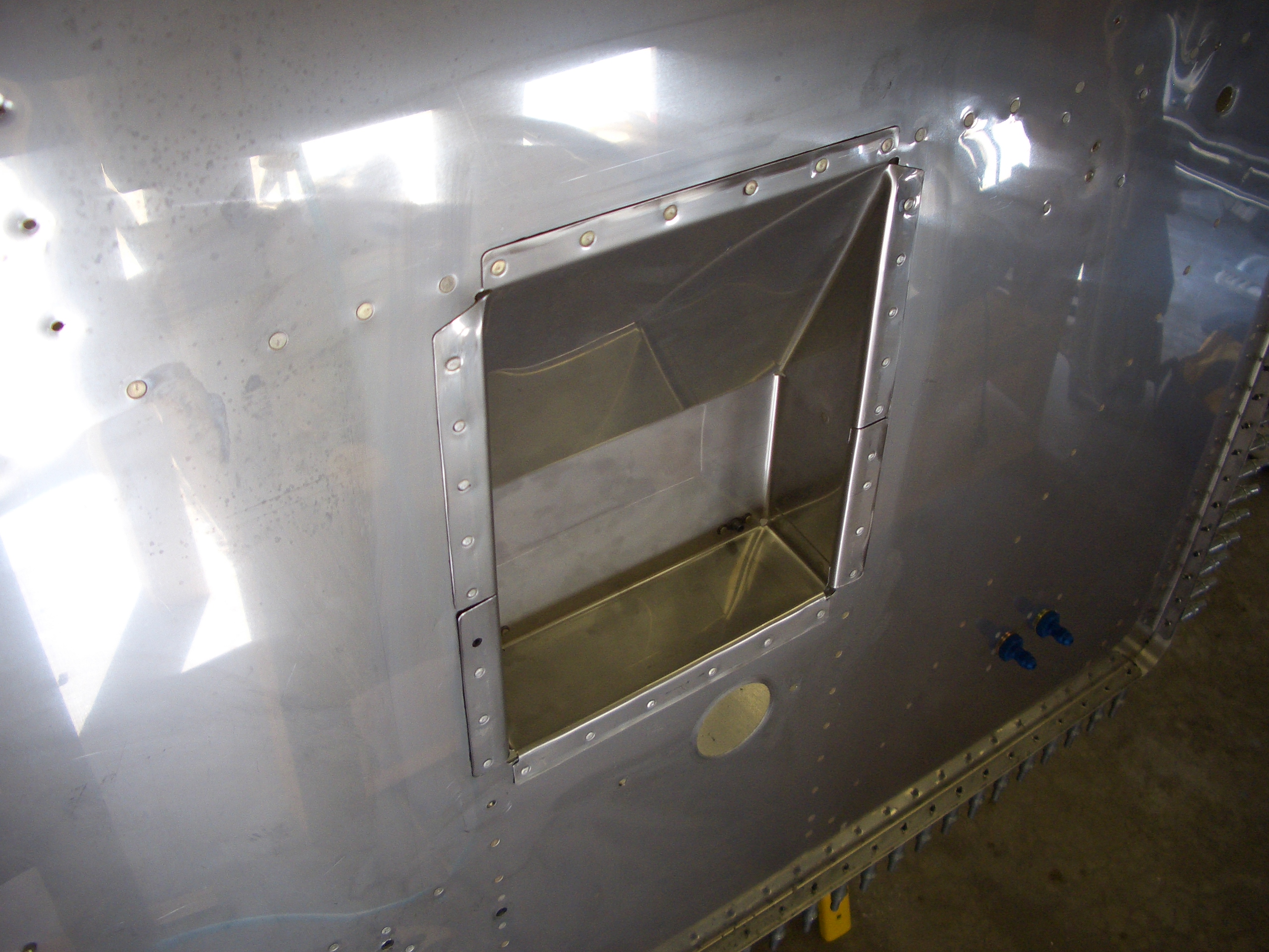
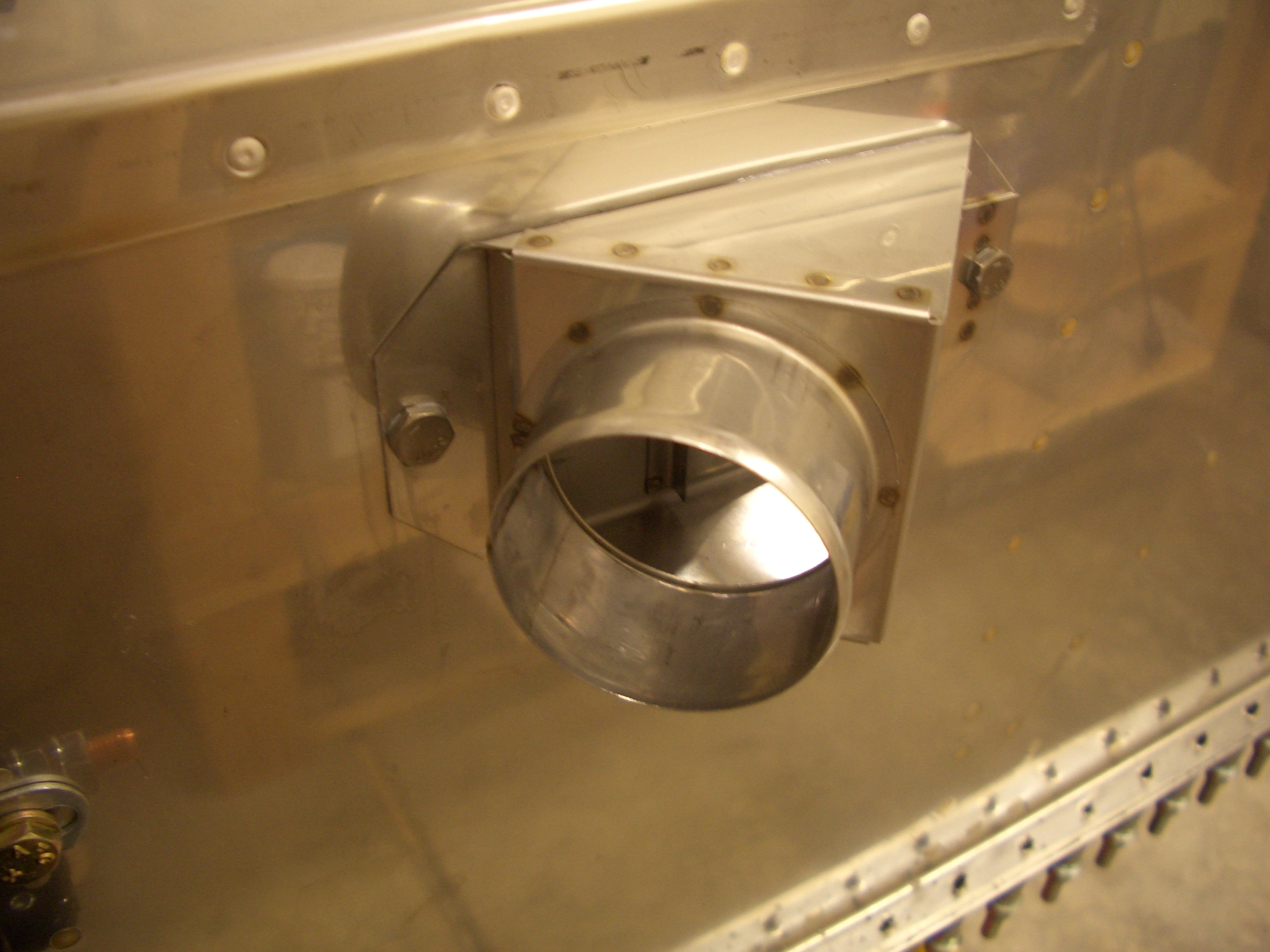
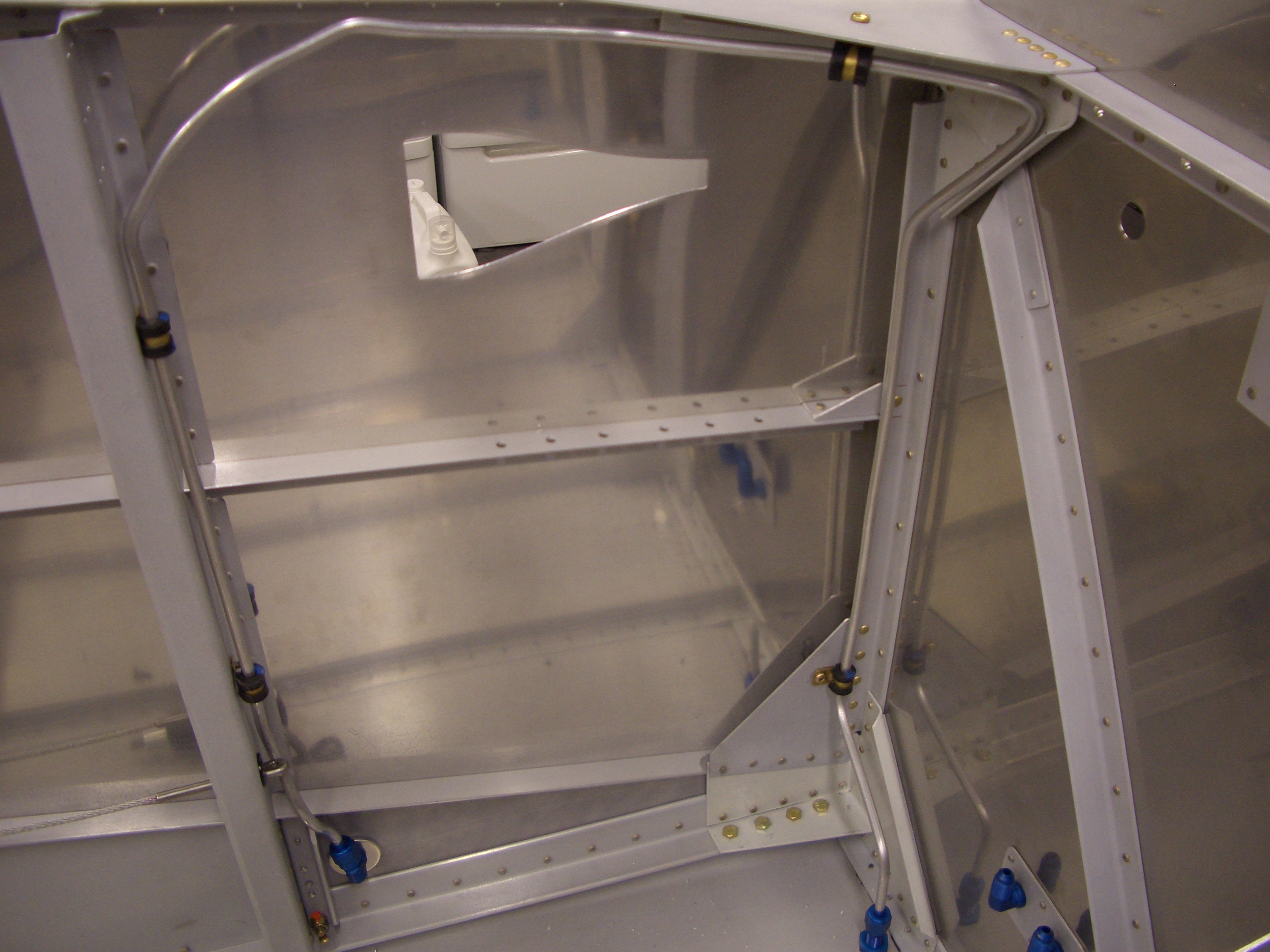
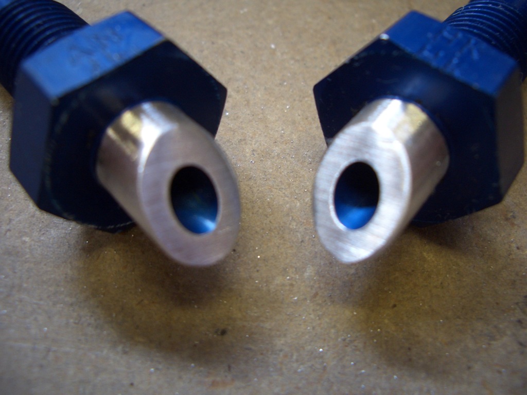
I knocked out the other fuel vent fitting this morning.  For freehand work, it looks nearly identical to the one I did yesterday.

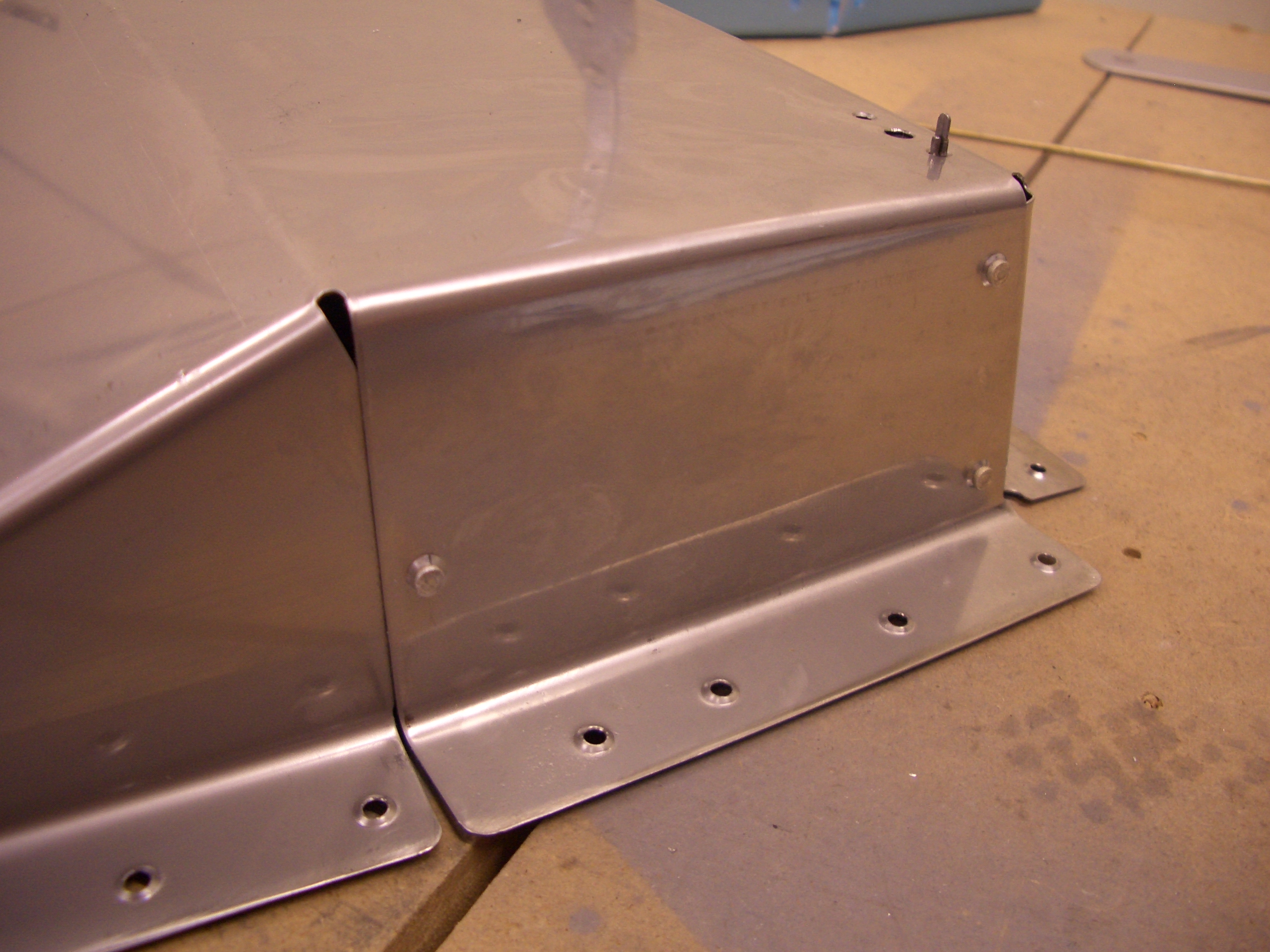
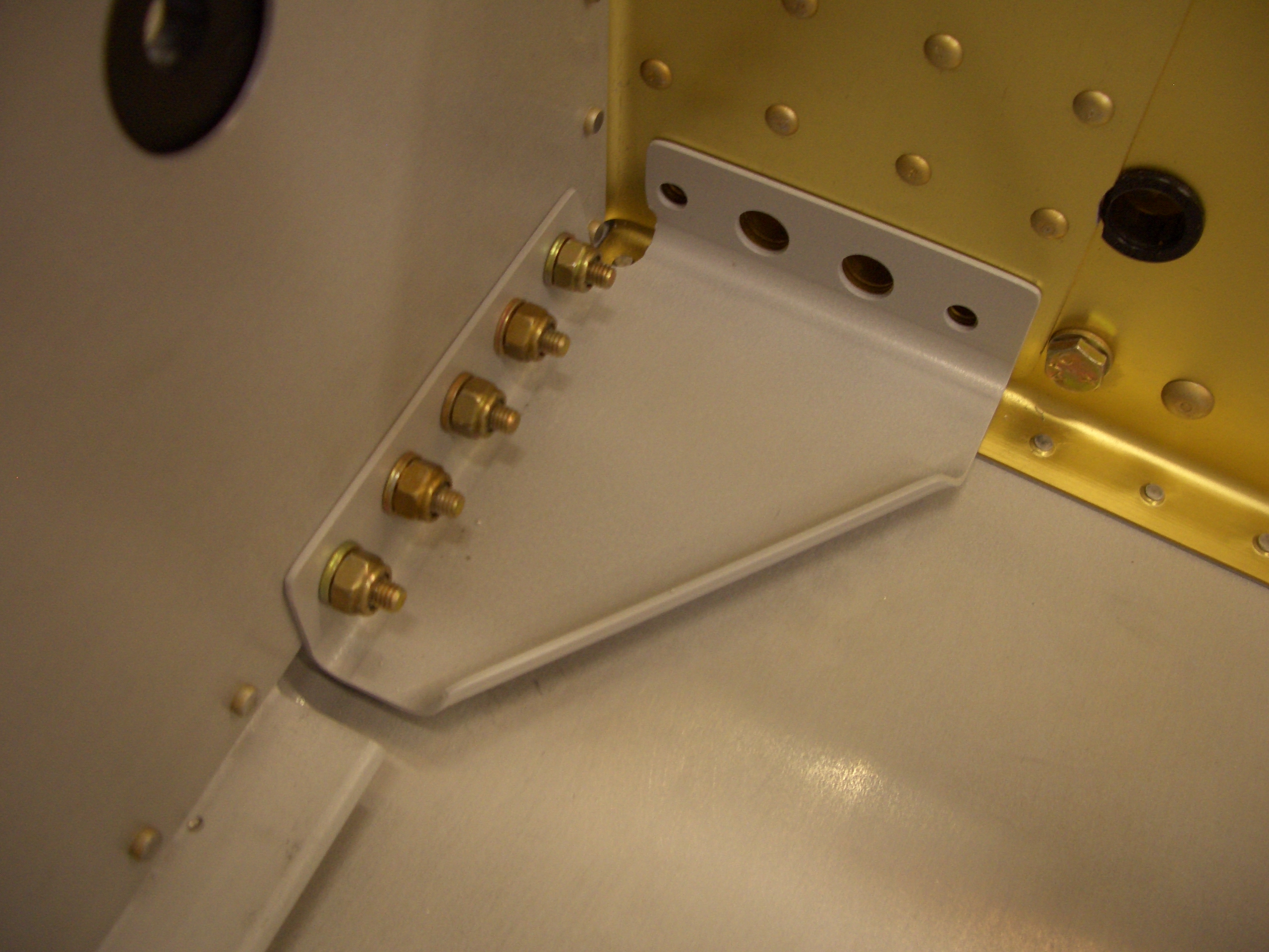
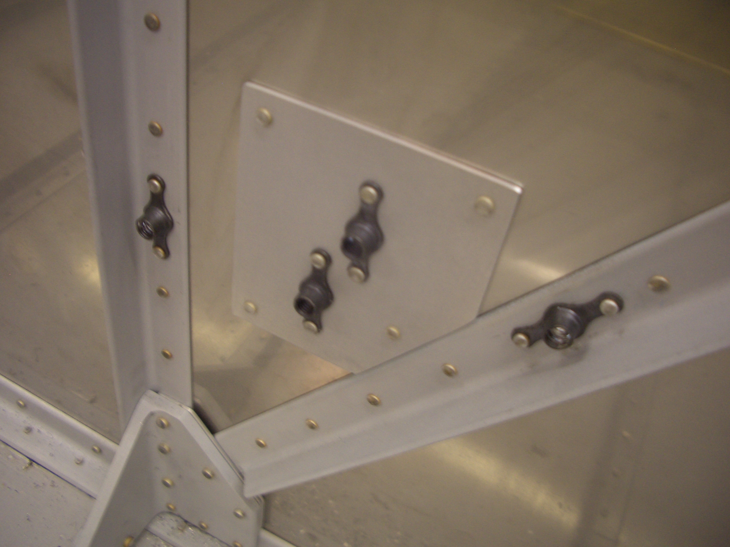
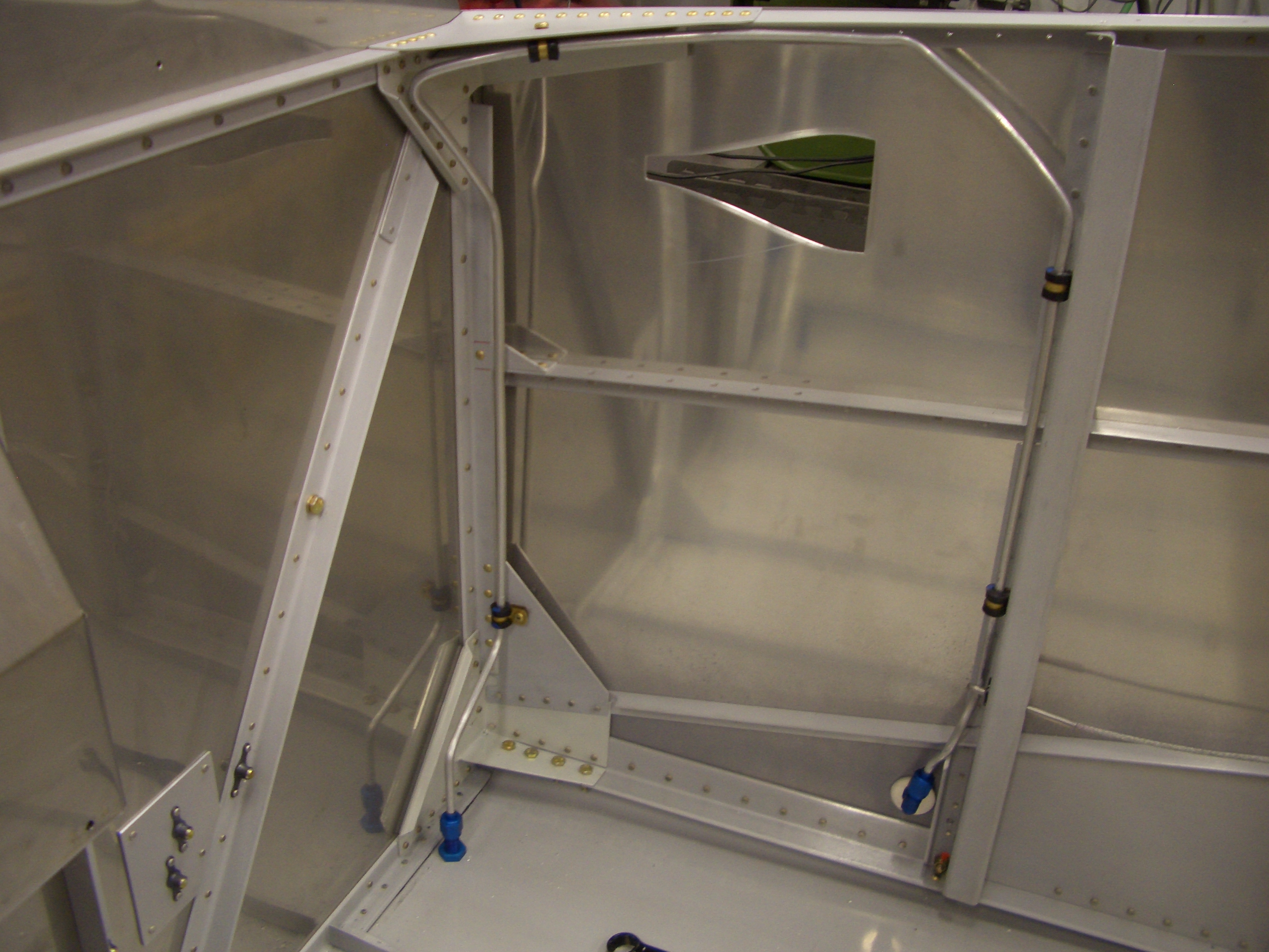
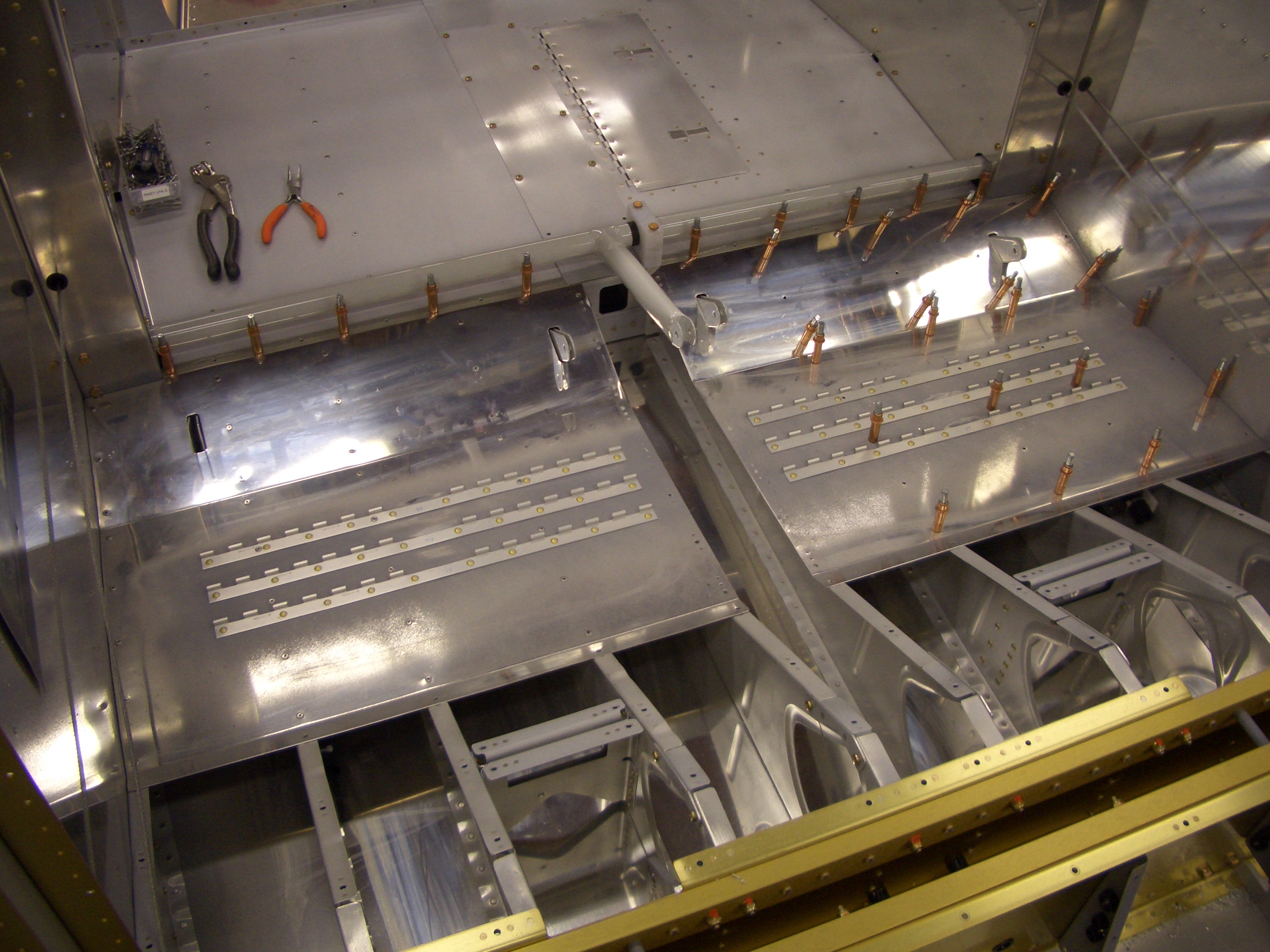
I started working on the F-7114 fuselage gussets.  As other builders have noticed, one of the rivets on the side wall (on the left) interferes with the flange of this gusset, preventing it from resting against the spar.

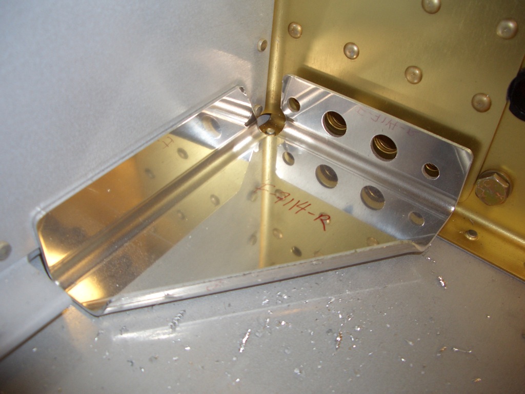
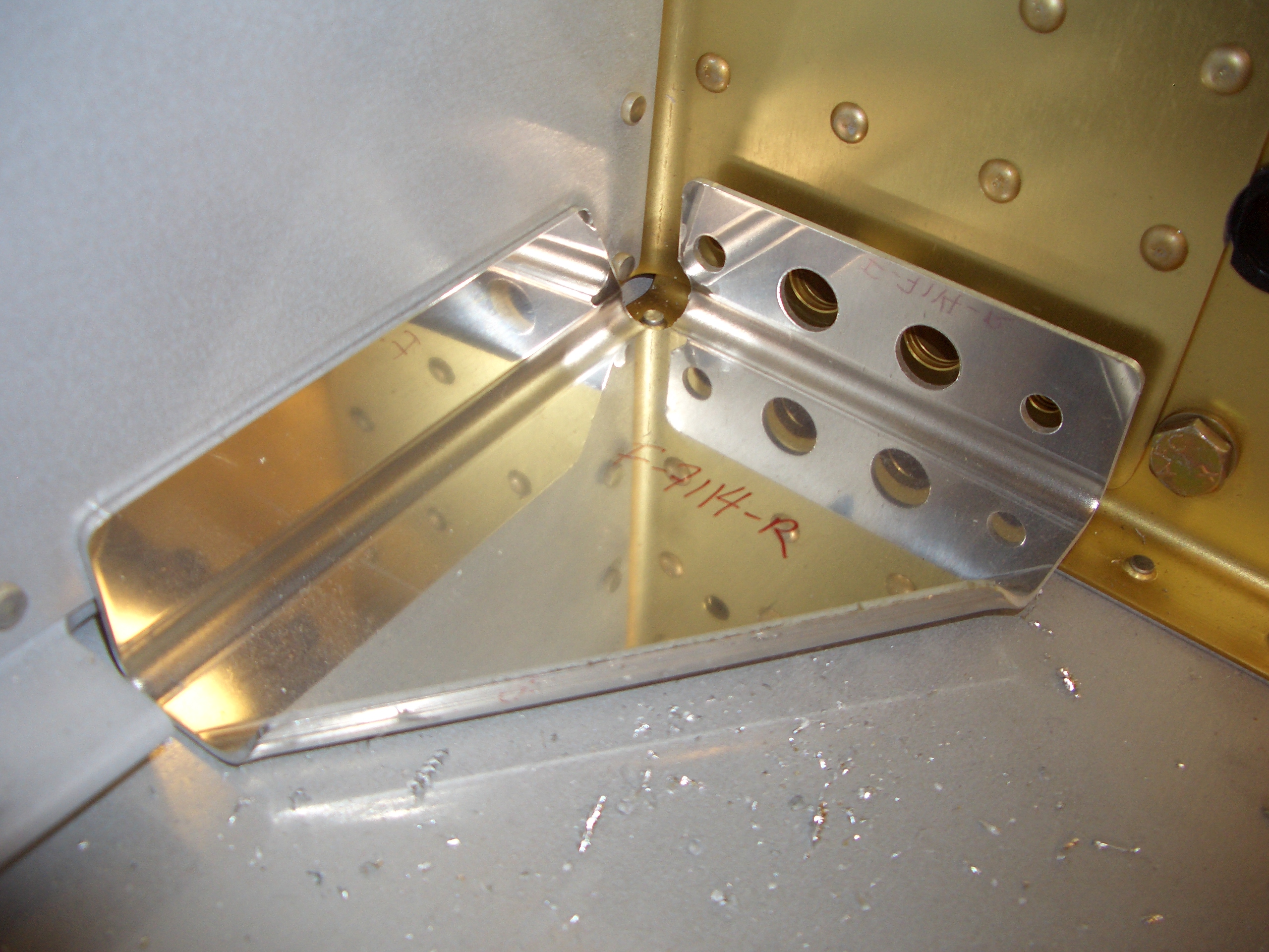
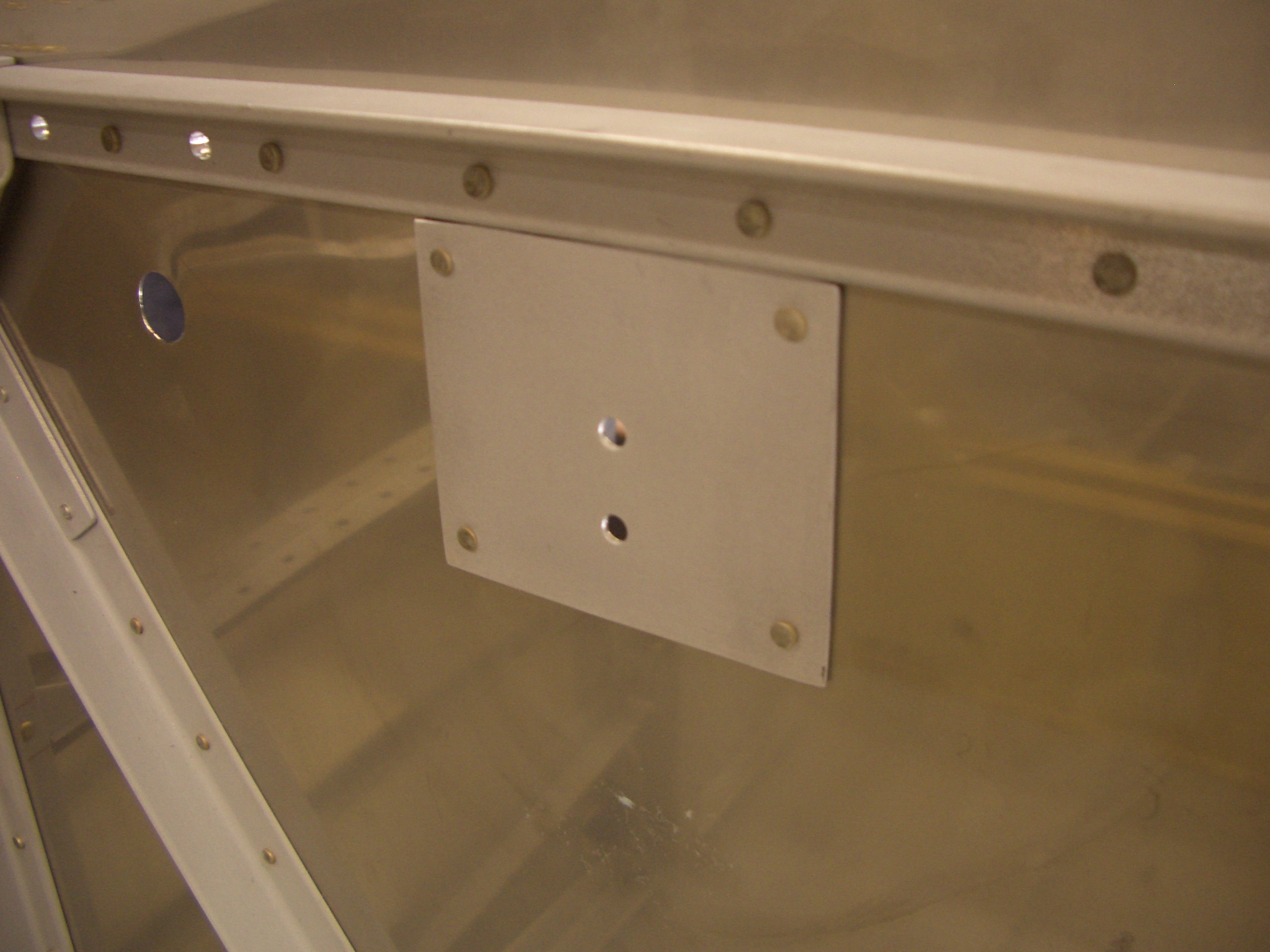
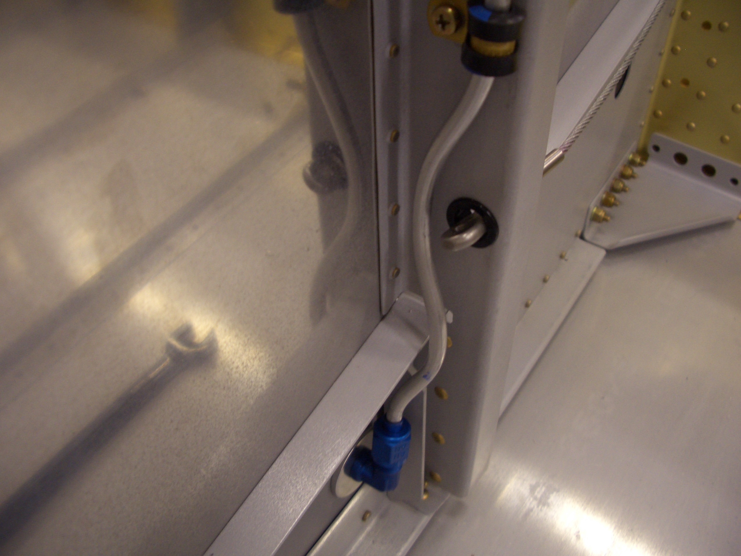
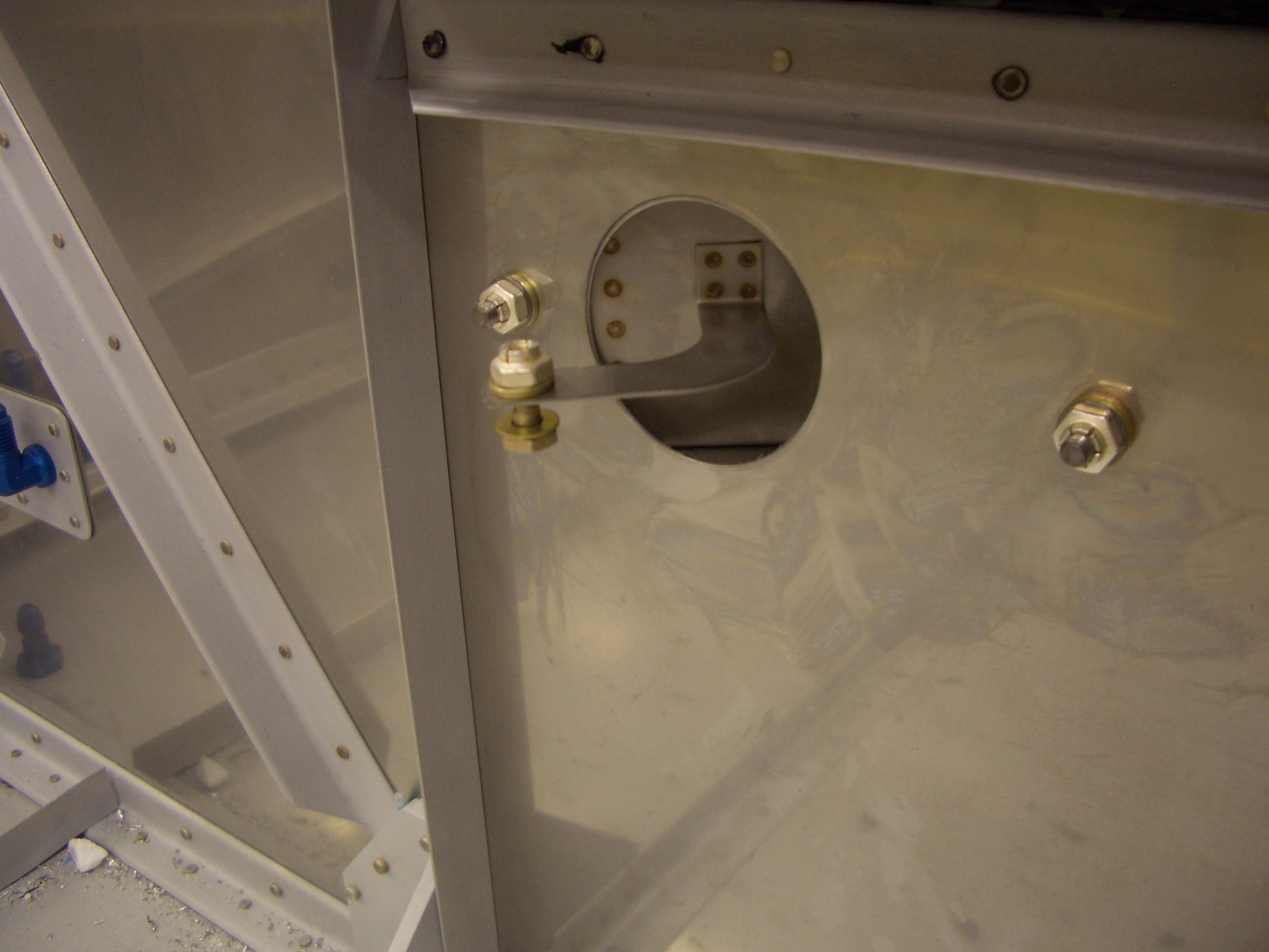
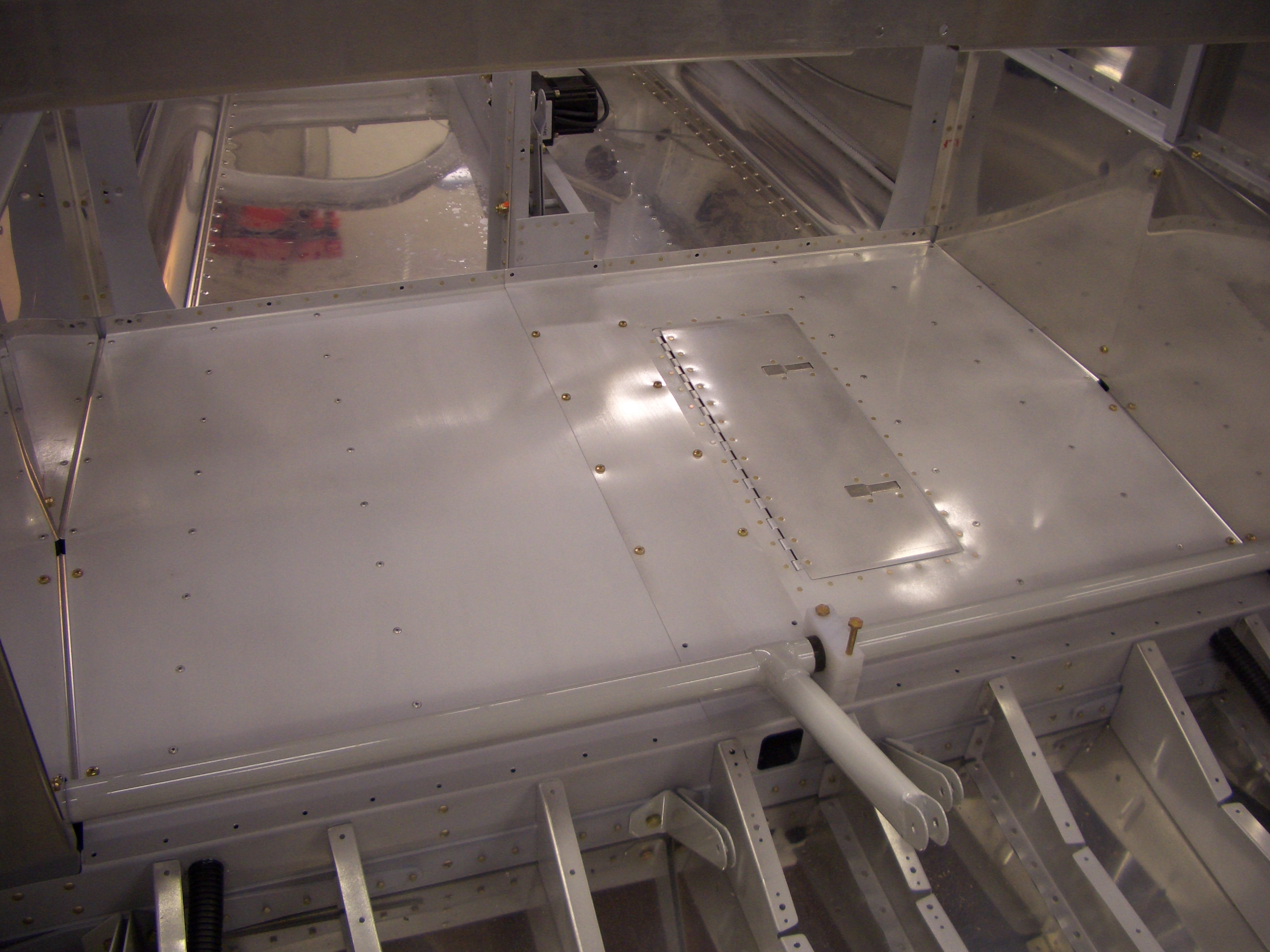
After relieving a bit of the gusset, I positioned it relative to the spar with some scrap bolts and drilled it to the side components.  There are five layers of aluminum here (the side and bottom skins, the lower longeron, the gear web, and this gusset.  This helps transfer load from the lower longeron to the spar.

Here are these holes from the outside.  I’ve only drilled them to #40 so far so that I could cleco the parts together to keep anything from shifting.

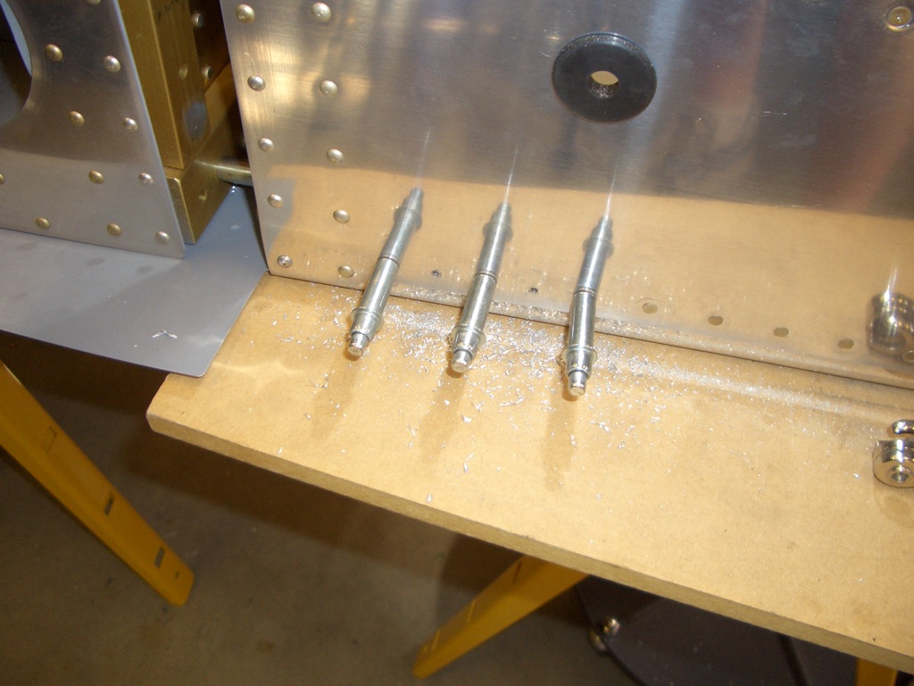
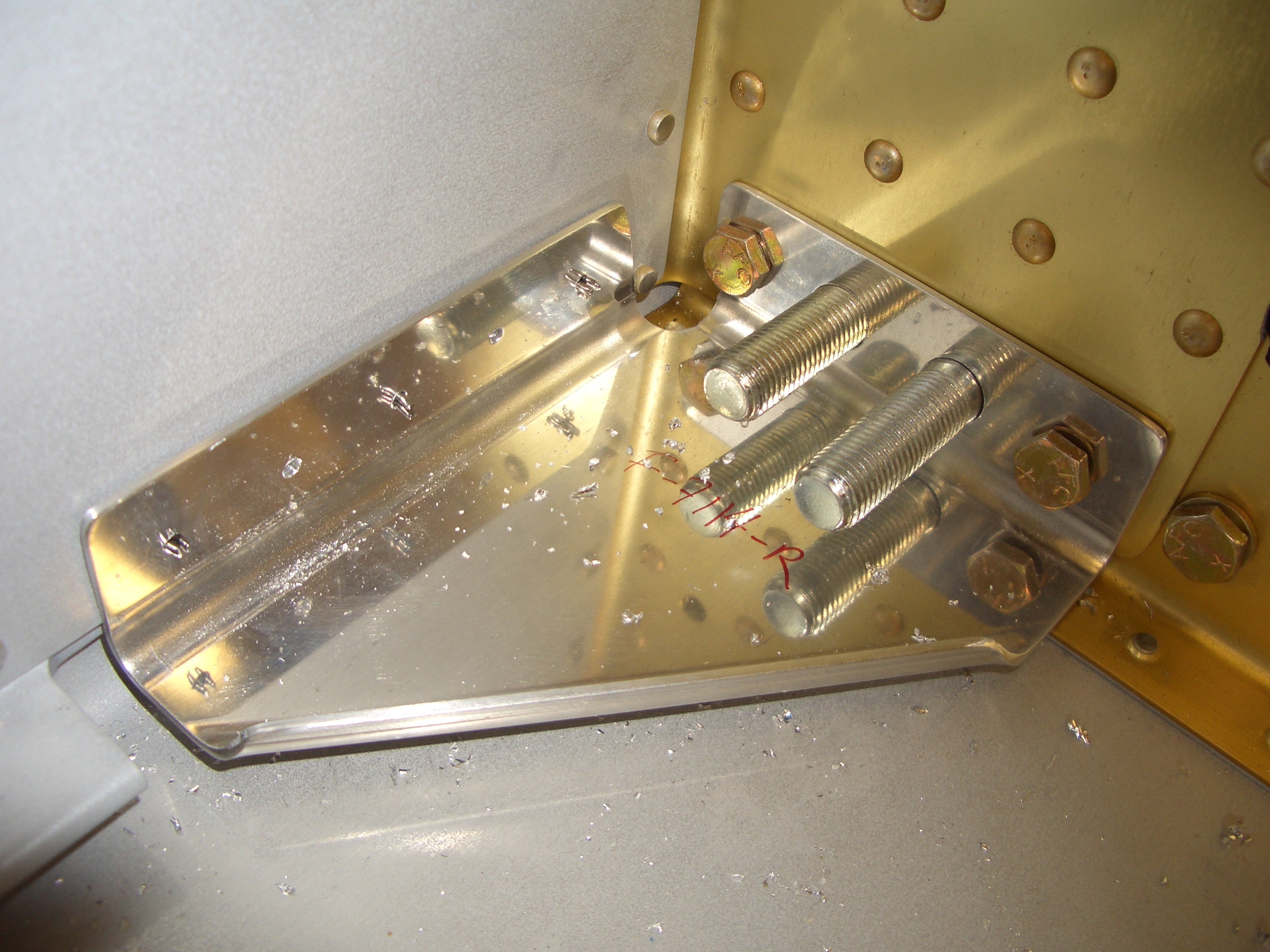
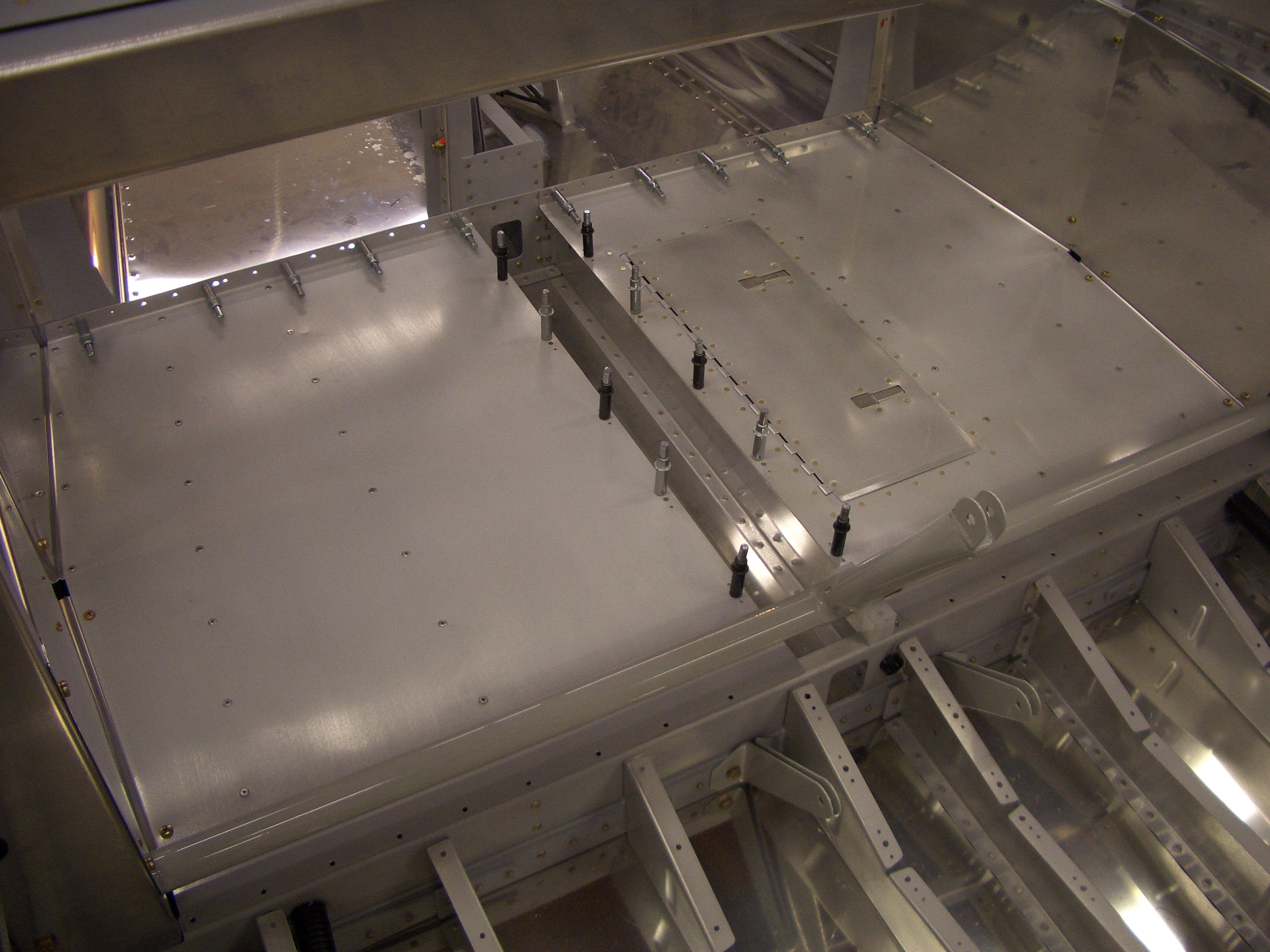
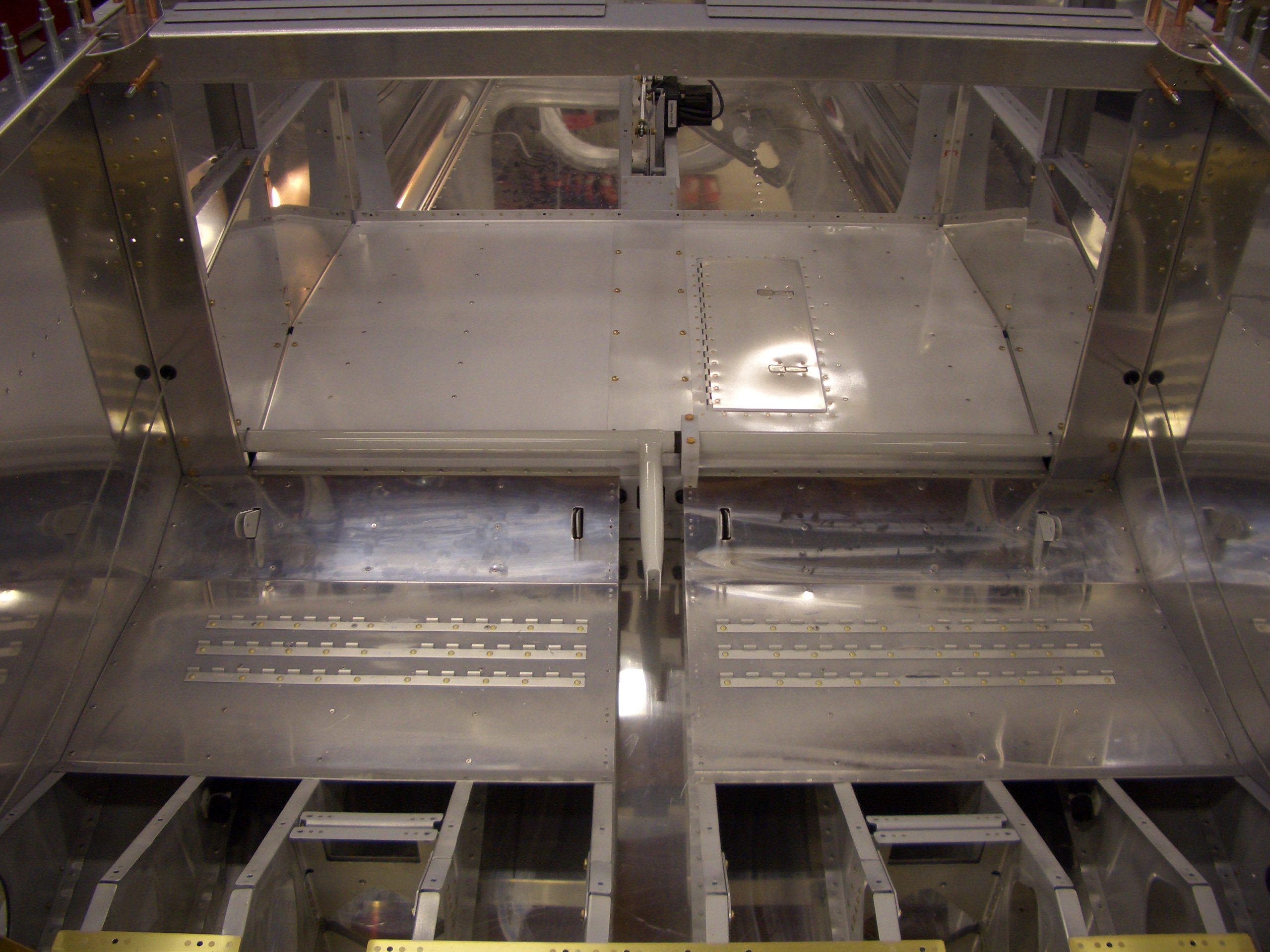
I then drilled/reamed the holes for AN3 bolts.

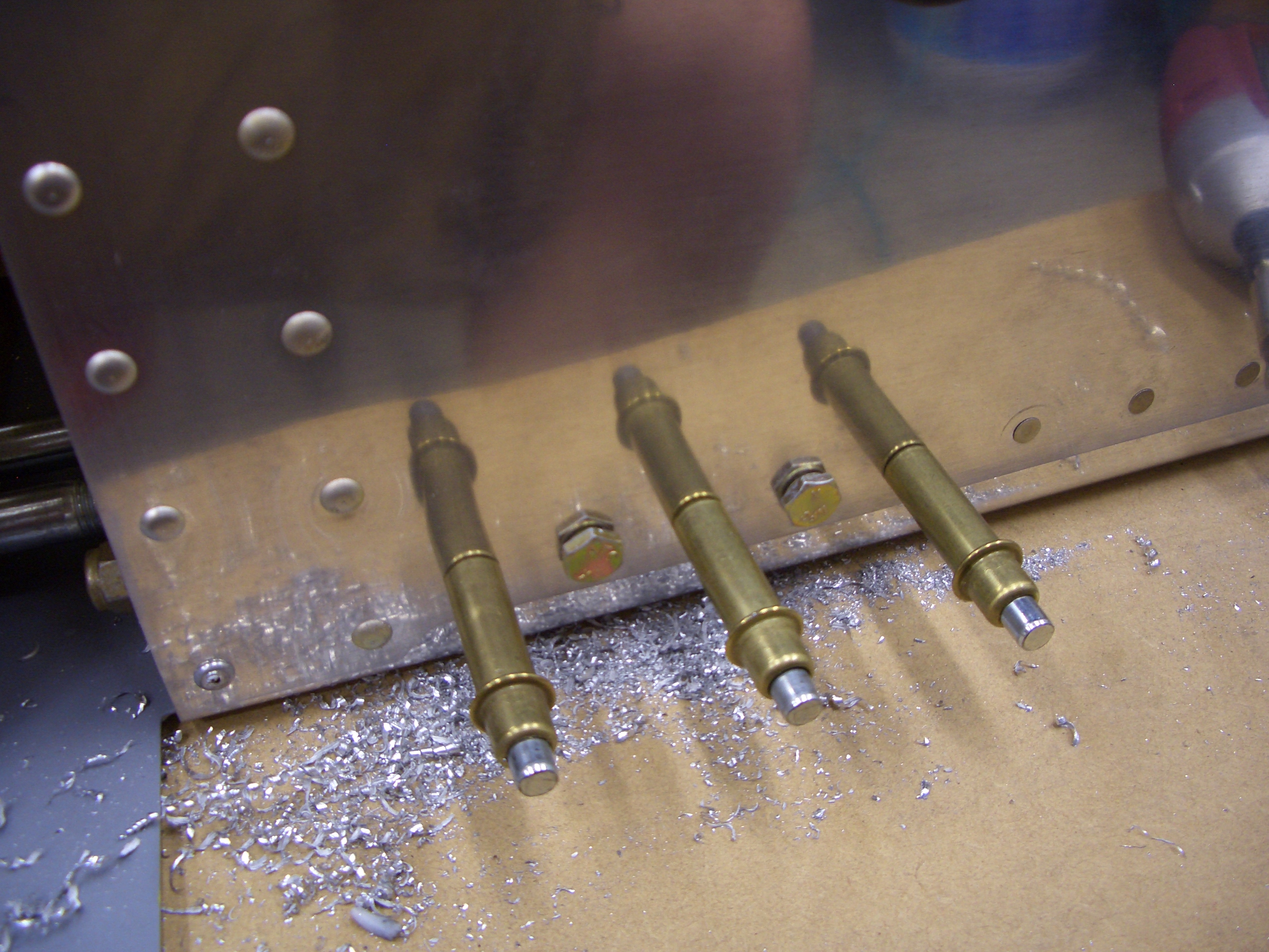
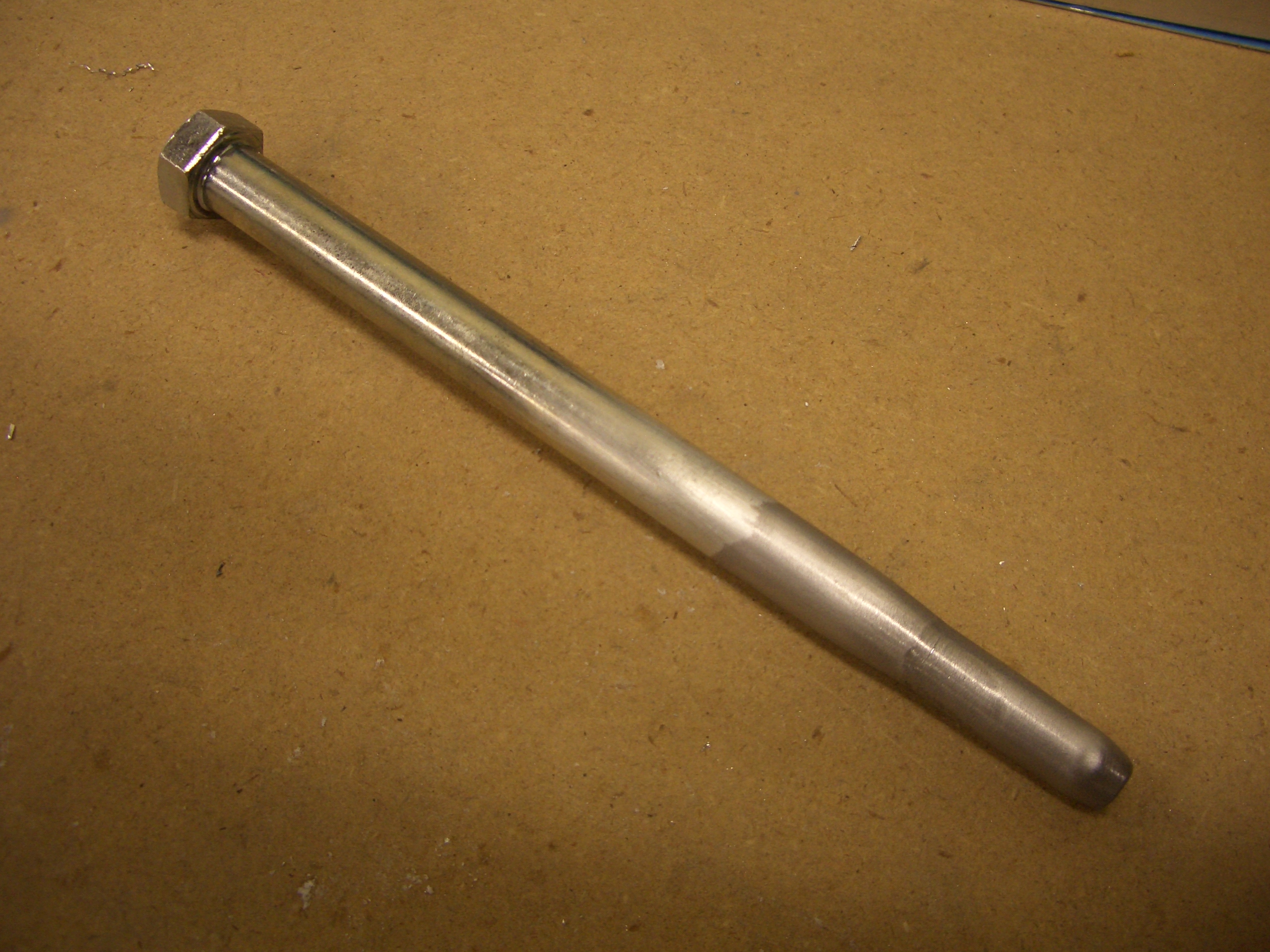
I purchased a long hardware store 7/16″ bolt a long time ago to make a drift pin to use when installing the wings.  For some reason, I decided to do that tonight.  I ground down the threads and beveled the shank in a couple of spots.  When the wings are installed, this can be lubricated and hammered into place to pull the holes into alignment.

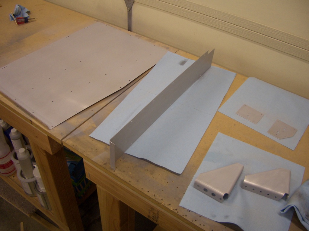
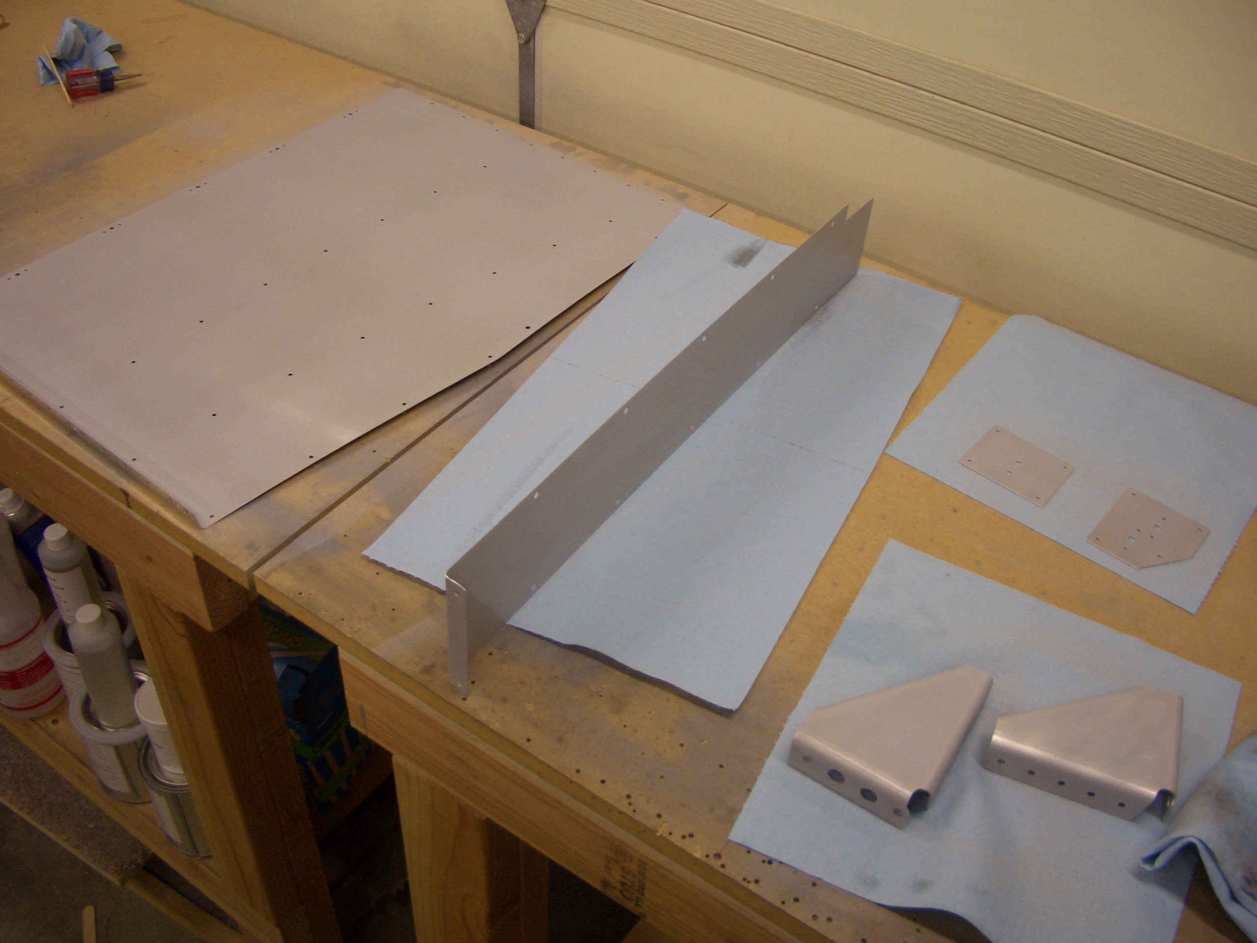
I finished the night by priming a small stack of parts that has been piling up.

Heater Box, Firewall Recess, Fuel Vents

I drilled the mounting holes in the firewall for the heater box.  Here I just have a couple of AN3-4A bolts temporarily holding it on.  I have some AN3C-4A bolts on order for the permanent attachment.

I prepped the firewall recess for riveting by deburring the rest of the edges, dimpling all around, and riveting the sides.  I dimpled these holes as well so the recess will be flush on the inside.

I started fabricating one of the fuel vent fittings by taking an AN832-4D bulkhead fitting and sanding off the threads on the short end and cutting a 45º bevel in the end  I’ll proseal a small stainless steel vent over the end to keep bugs out.

Installed Autopilot Pitch Servo

I dug out the autopilot pitch mounting kit and installed the servo into the mounting bracket.  It took a couple of tries, but I got it safety wired.

I then installed the elevator bellcrank and hooked up the pushrod.

The servo comes with a limiting bracket to prevent the arm from going over center and binding the controls.  I installed it so that the arm can go about 80º to either side of the point where the arm is 90º to the pushrod.  In practice, the elevator will hit the control stop long before the servo arm hits the limiting bracket.  Update: This bracket is installed incorrectly.  Please refer to the Dynon installation instructions for the correct orientation.

Finished Parking Brake Line and Cut Hole For Heater Box

I fabricated the other line from the parking brake valve to the firewall fittings.  As is typical, the second one took a fraction of the time of the first.

I don’t have a 2″ hole saw, and I didn’t want to buy one just for this one hole, so I used my fly cutter in a handheld drill.  I went slow and it went fine.  At no time did I feel like this was dangerous, but by no means am I recommending that you do this.

Worked on Brake System

I drilled the firewall and stiffener for the brake fluid reservoir.  This has mounting ears that are bolted through the firewall stiffener.  I installed this on the left side of the firewall instead of the right since I’m only installing pilot side brakes.

This is the cabin side.  These are the wrong length bolts (obviously), but were just used for positioning.  You can see where the fitting threads into the reservoir.  Hoses will attach here to provide fluid to the master cylinders.

I positioned the Grove parking brake valve just to the right of the reservoir.  I determined the horizontal position by positioning the activation arm just to the right of the rib so that I can attach the cable mount to the rib.

Next up, I used some left over 1/4″ 5052 tubing to fabricate lines that tie the brake valve to the fittings on the firewall.

Here you can see that the line has to jog around the firewall stiffener.  It’s late, so I’ll take care of the other line tomorrow.

Fit Battery Box and Finished Contactors

I fit the battery box to the firewall and drilled the three mounting holes an AN3 bolts.  This can’t be installed permanently now since the firewall recess hasn’t been riveted on.

Here’s the battery in the box.  I’ve taped off the posts so that I don’t accidentally short anything across the battery.

I fabricated the hold down strap from some aluminum bar stock.  This gets held down with a couple of AN3 bolts that run through some spacers I made so that the bolts can be torqued down without putting excessive force on the top of the battery.  The battery weighs almost 15lbs, and the plane is rated to handle 3 negative Gs, so the strap needs to handle at least a 45lbs load plus a healthy safety margin.

I also fabricated the firewall stiffener for the center attach points of the two contactors.  Since I adjusted the position of the contactors, this also isn’t to plans.  I basically just roughly centered the plate horizontally and vertically on the pair of center holes and then laid out four rivets around the perimeter to tie it to the firewall.  I didn’t get a picture of it, but I then final drilled/reamed the center holes to 1/4″ and then drilled for nutplates.  I want to prime this plate, so I didn’t get it installed tonight.  I’ve got a pretty big pile of parts that needs priming how, so I should probably have a priming session in the next few days.

Powder Coated Battery Box Components

I painted the battery box and mounting angles a couple of days ago.  The paint on the box came out fine, but it bubbled up on the angles.  These were previously powder coated, but I sanded and cleaned them before painting, but apparently, something went wrong.  I considered stripping the paint off and trying again, but I had been looking for an excuse to buy a powder coating system anyway, so this was as good of an excuse as any.  I stopped by Harbor Freight this morning and picked up their system as well as a few colors of powder.  After stripping the paint and old powder coat, I re-powder coated these and baked them in a cheap little toaster oven I picked up at Target.  These turned out fantastic.  I really wish I had bought this earlier so that I could have powder coated the tailwheel spring mount.

Here’s the finished box with the side angles riveted on.

Started Installing Battery and Starter Contactors

Since I positioned the contactors far enough apart vertically that the mounting ears didn’t interfere (which is not according to plans), I couldn’t use the stock positioning.  Instead, I simply adjusted the pair vertically until the outboard ears intersected with the firewall stiffener centerlines and marked the holes.  I then drilled and installed L1000-4 nutplates on these holes.

Here’s the cabin side.  I had to countersink the firewall and stiffener for the AD3 rivets that attached the nutplates.  I’ll drill the center holes later.

Worked on Battery Box and Contactors

I received my battery and install kit from Van’s today, so I wanted to take a break from the forward fuselage and install it.  Van’s specifies optional lighting holes in the steel mounting box.  I want to take advantage of any opportunity to remove weight from the plane since I’m going with a full interior.  I used my fly cutter in the drill press and knocked these out in 15 minutes or so.  It turns out that four pieces of 3/4″ wood fit exactly inside the box, so I used them to back up the top surface when drilling the holes.

Next, I clamped sude support angles in place and match drilled them to the battery box.  The left side is flush with the back wall of the battery box, but the right side is offset forward about 0.024″ to make room for the firewall recess and the thickness of the firewall sealant.  To do this, I set the angle on a piece of scrap stock.

After deburring and dimpling the battery box and angles (the box needs flush rivets on the inside so that they don’t interfere with the battery), I painted the box and mounting angles with some gloss black paint.

While waiting for the paint to dry, I fabricated the connection between the battery contactor and starter contactor.  Instead of using a big wire with terminals on the ends, Van’s recommends positioning the contactors such that a solid copper bar can be used to connect the output of the battery contactor (silver) to the input of the starter contactor (black).  Van’s recommends using two pieces of 1/16″ thick copper and sells this stock.  Aircraft Spruce sells 1/8″ thick stock for less, so this can be fabricated from a single piece.  I made the bar slightly longer than the plans so that the mounting ears don’t interfere.

Two diodes need to be mounted between the input of the starter contactor and the control terminal as well as between the left control terminal of the starter contactor and ground.  These contactors are basically electromagnets, and shutting off power to these coils causes the magnetic field to collapse which can generate voltage spikes of hundred to thousands of volts.  This causes arcing in the switches which can cause them to prematurely fail.  By using these diodes, the energy from the collapsing magnetic field can be safely dissipated.

Finished Center Subpanel

I laid out and drilled the holes that attach the forward engine control bracket to the center subpanel.  The throttle, prop and mixture control cable housings are anchored here.

The top edge has a seal support angle mounted 1/8″ below the top flange.  This will hold a piece of weatherstripping that will seal the forward edge of the canopy.  I first laid out the holes according to the plans and used the rivet fan to drill them to #40.  To position it, I clamped a flexible aluminum ruler to the forward flange and then clamped the seal support angle to that with some 1/8″ spacers between them.  I then match drilled the subpanel and then opened the holes up to #30.

The seal support angle and engine control bracket are then riveted to the center subpanel.  I didn’t prime these parts because these will be visible when the canopy is opened, so I want to paint it with my interior color.  Since there is a lot of work in the upper forward canopy over the next 6 months or so, I’m going to hold off on painting this to avoid scratching it up.

I also riveted on the F-644-L/R forward fuselage channels.  These require flush rivets on the outside faces because the canopy hinge bracket rubs against an UHMW plastic block mounted here.  The plans also show the support seal cut off flush with the channel, but the plastic block is 1/8″ thick, so I left the support angle a little long.