Drilled Left Forward Skin Stiffener

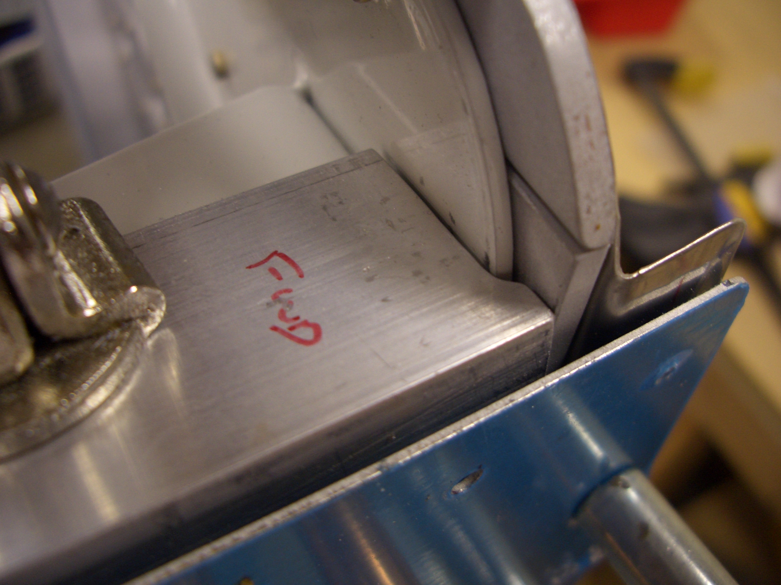
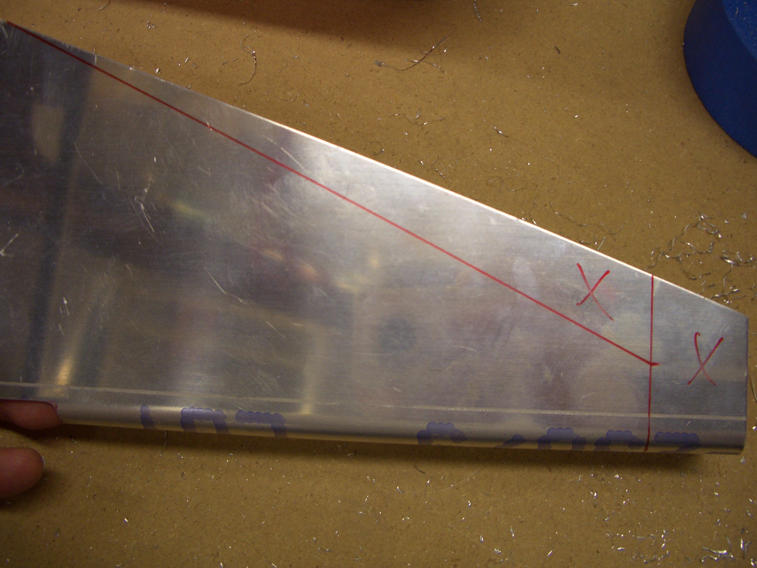
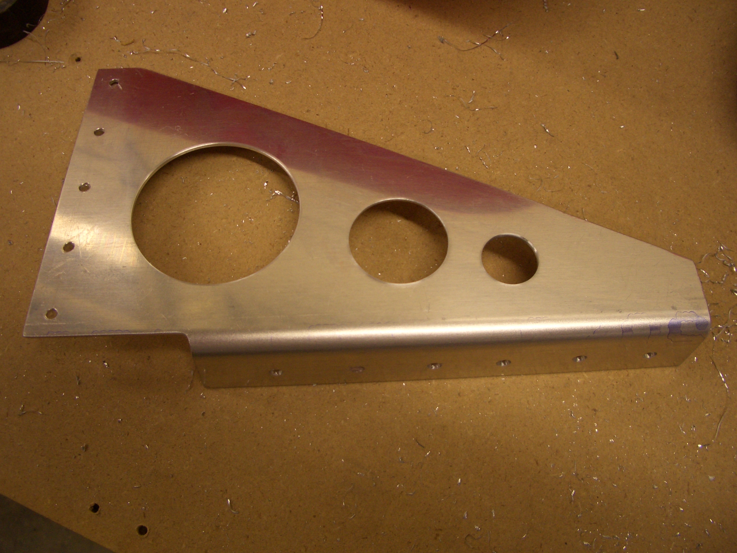
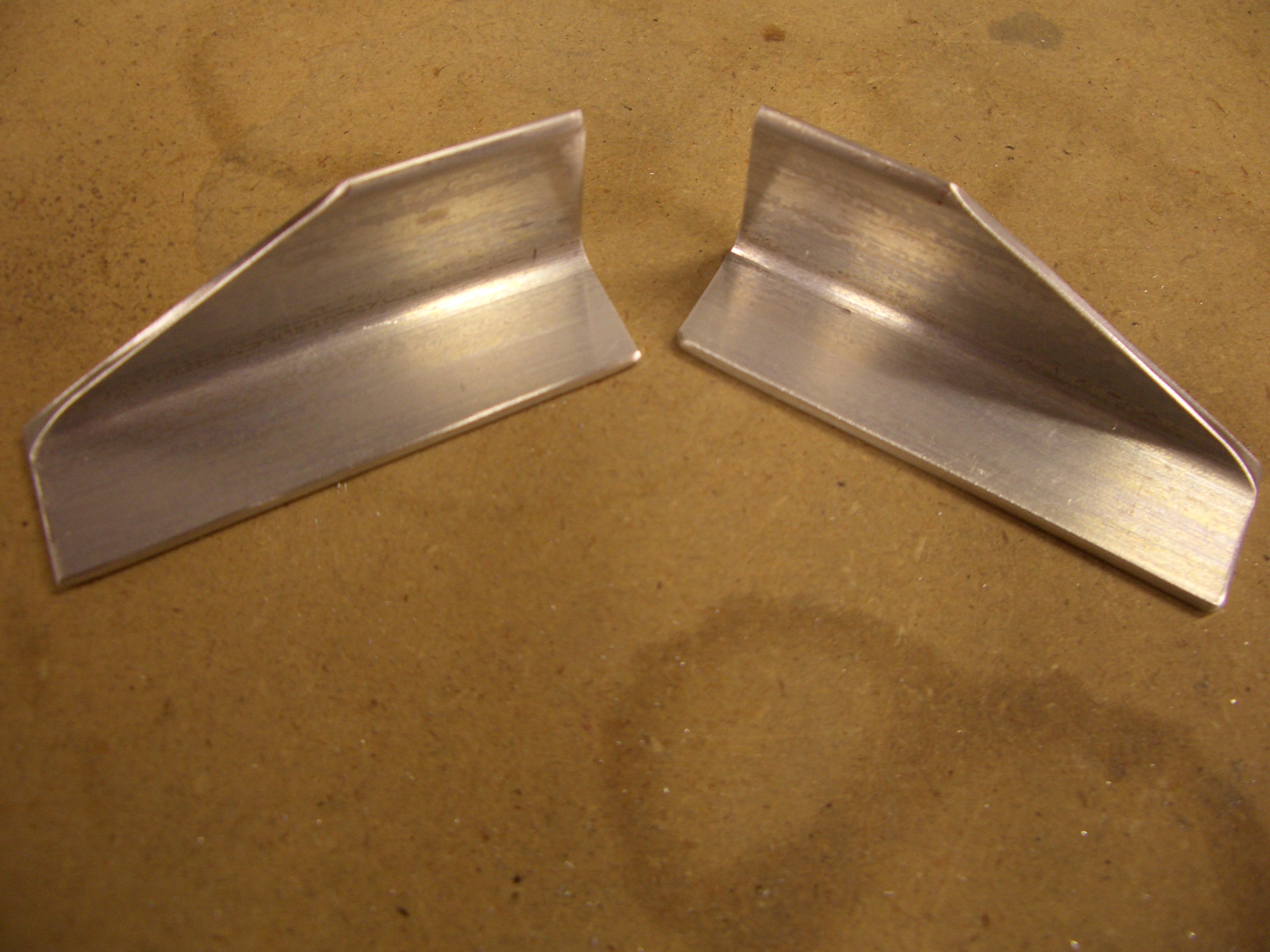
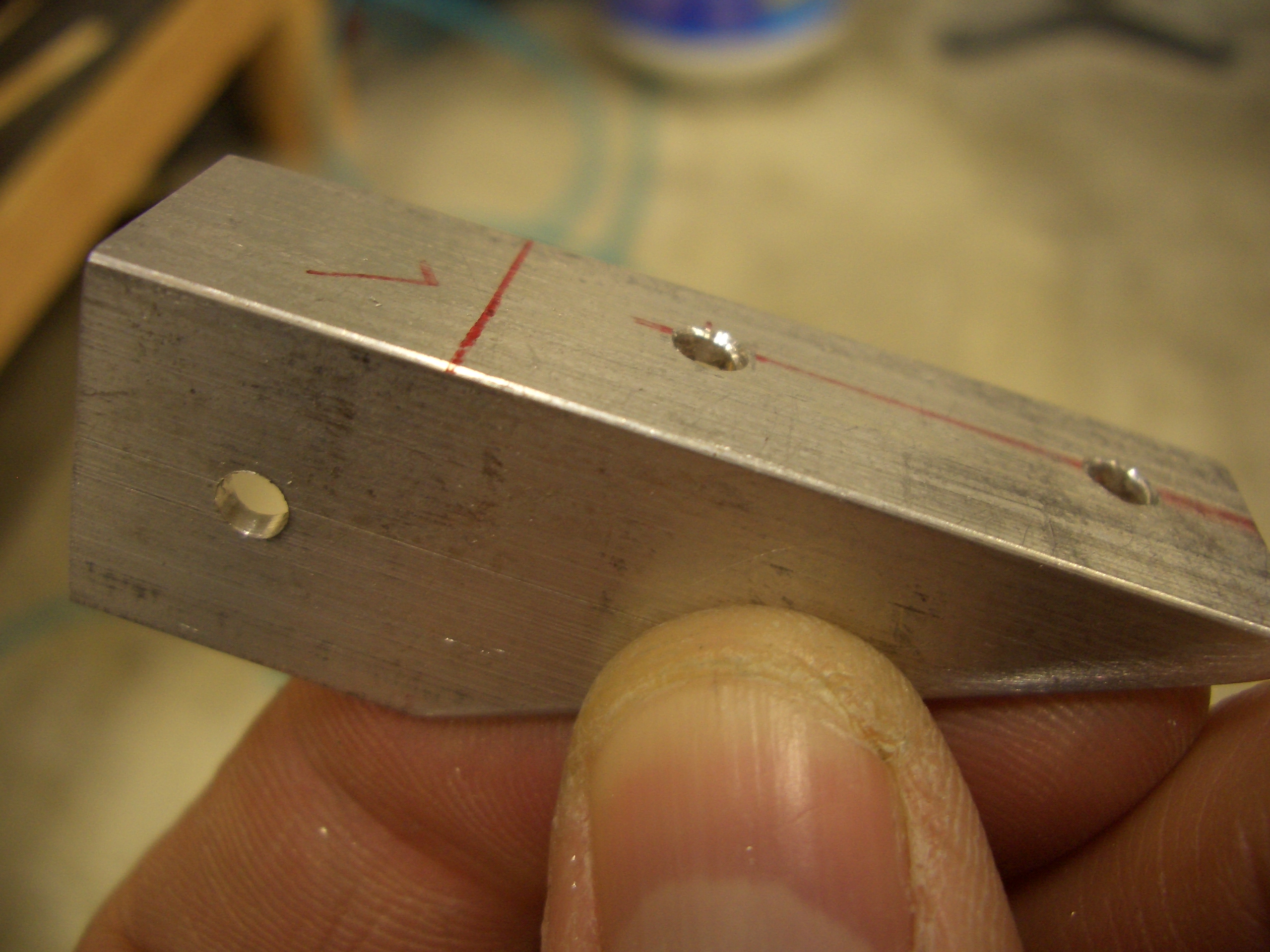
I fabricated the two F-719B angle clips from some raw stock.  I subsequently drilled the two holes on the edge that mates with the skin stiffeners.  I didn’t drill the hole in the other leg since there would then be no easy way to match drill it to the firewall stiffener.

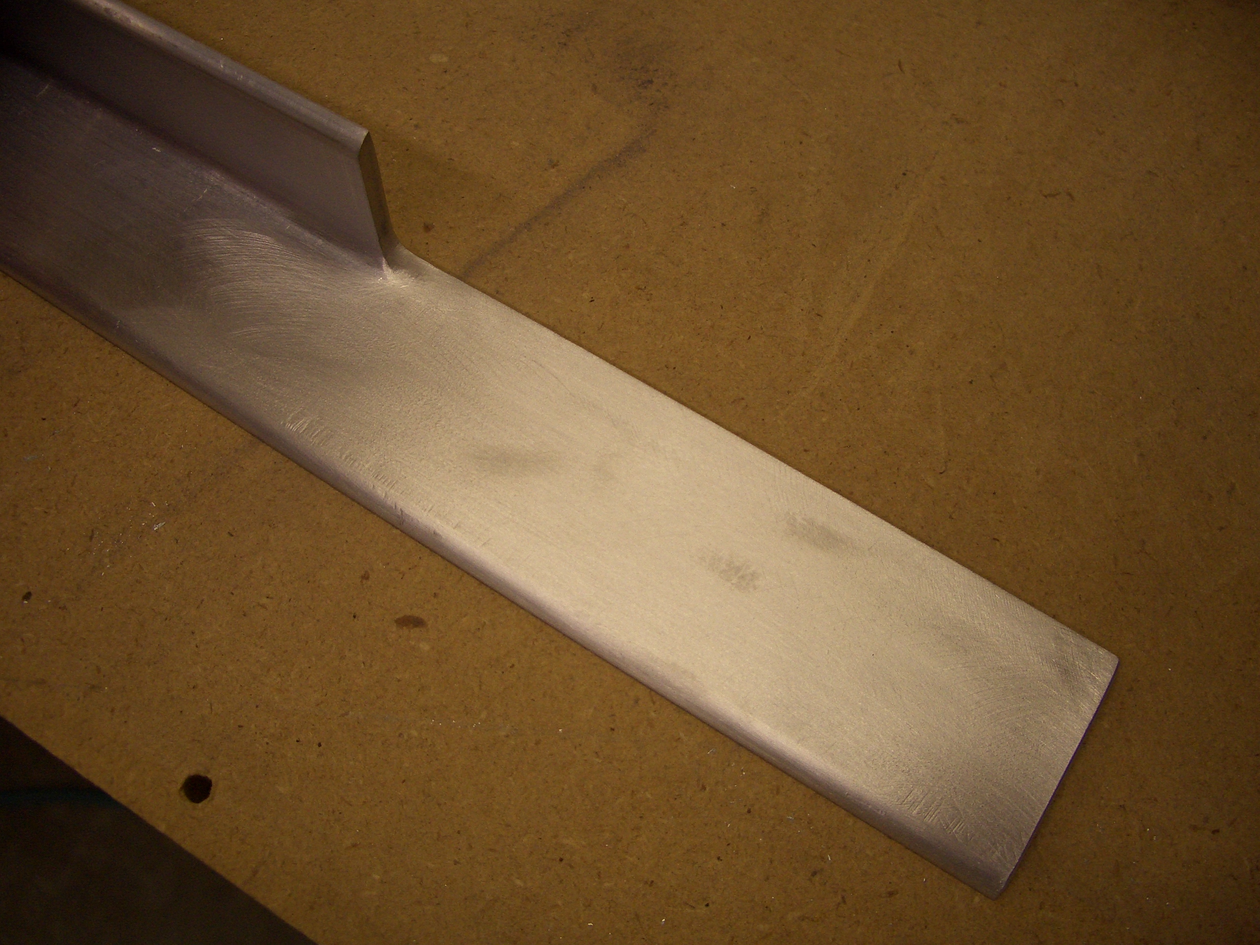
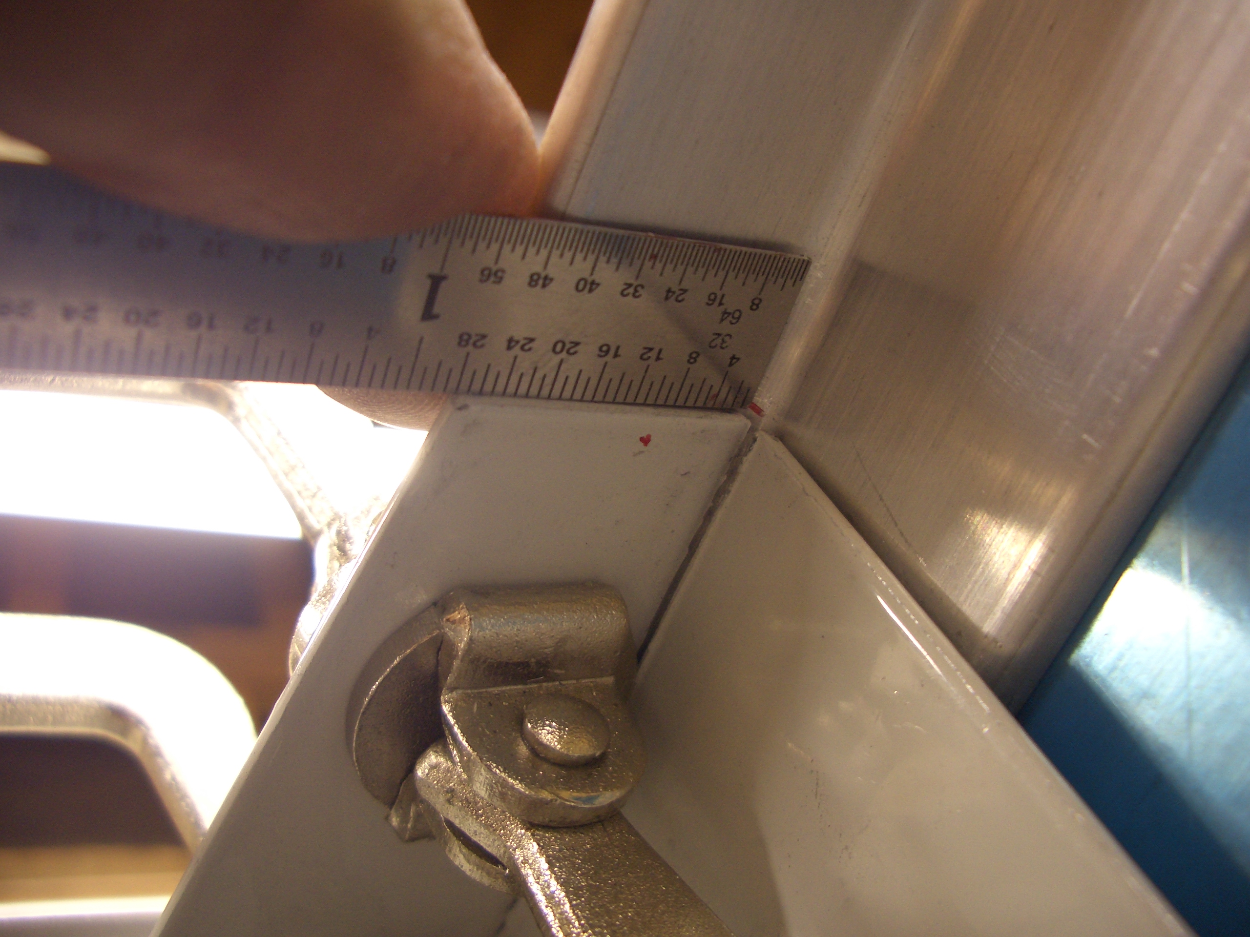
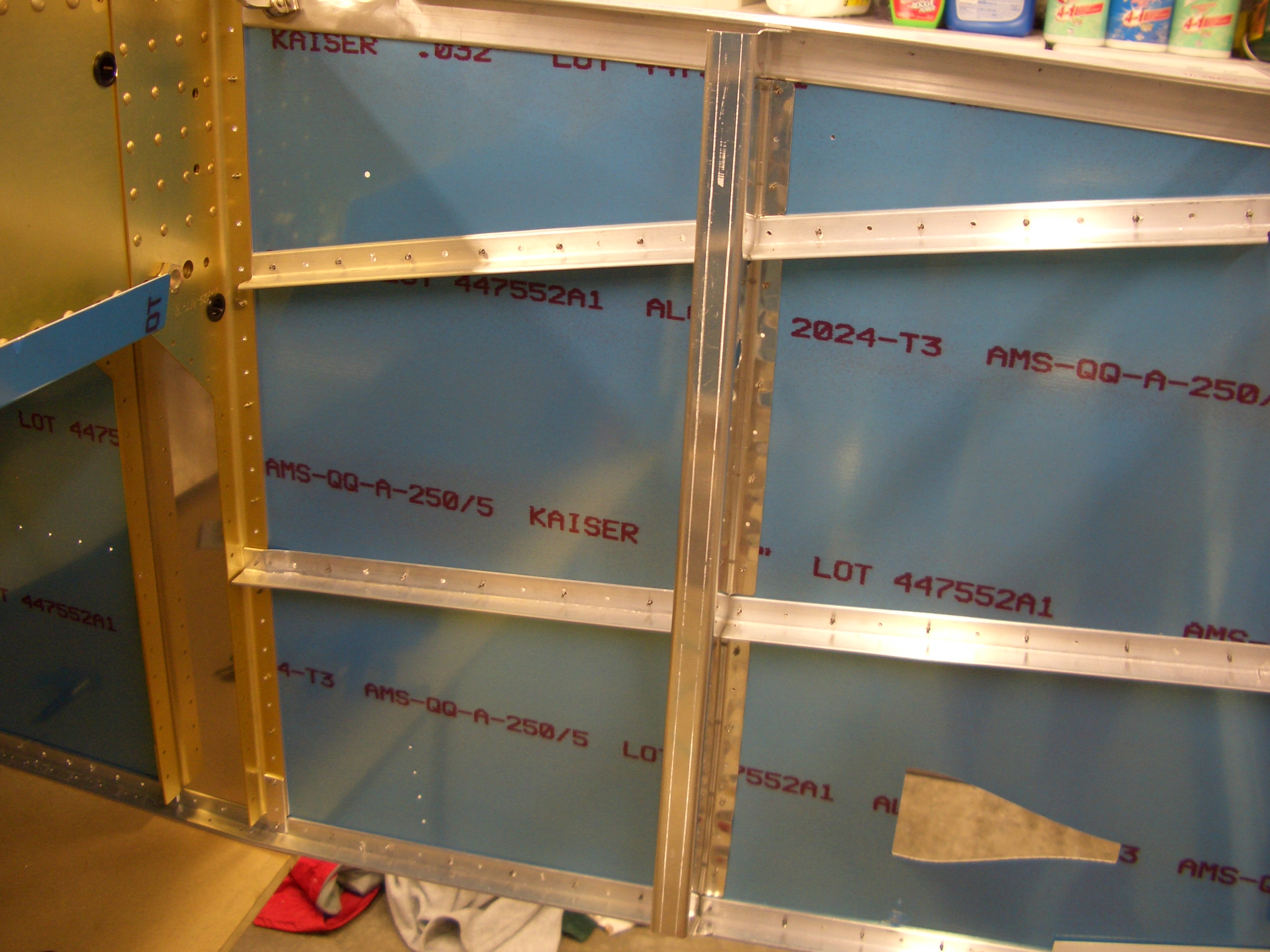
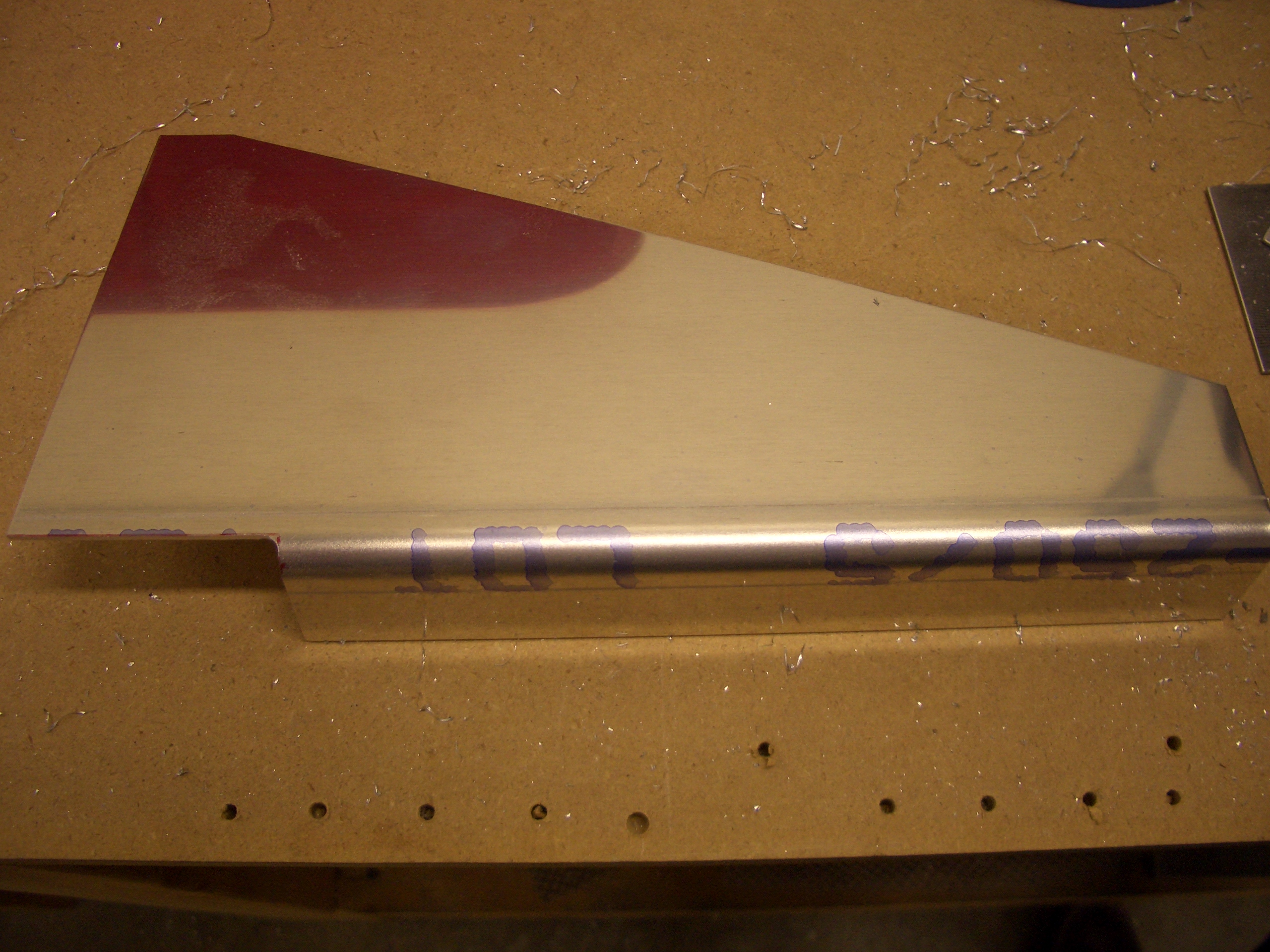
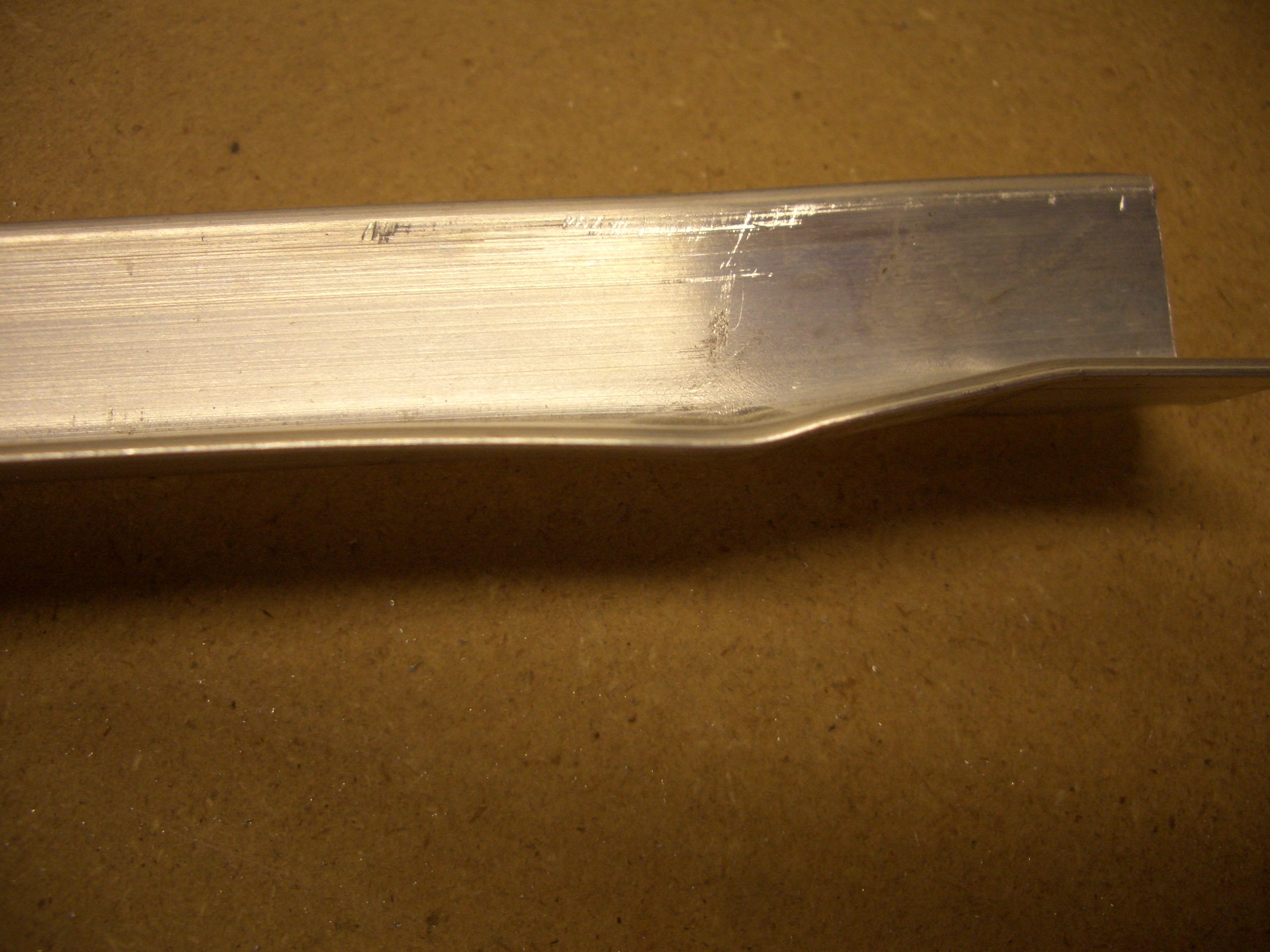
The side stiffeners are rather poorly bent from the factory.  The joggle is necessary so that the stiffener can overlap F-704, but the way they bend these causes the leg of the angle near the joggle to bend outward which prevents it from lying flat on the skin.

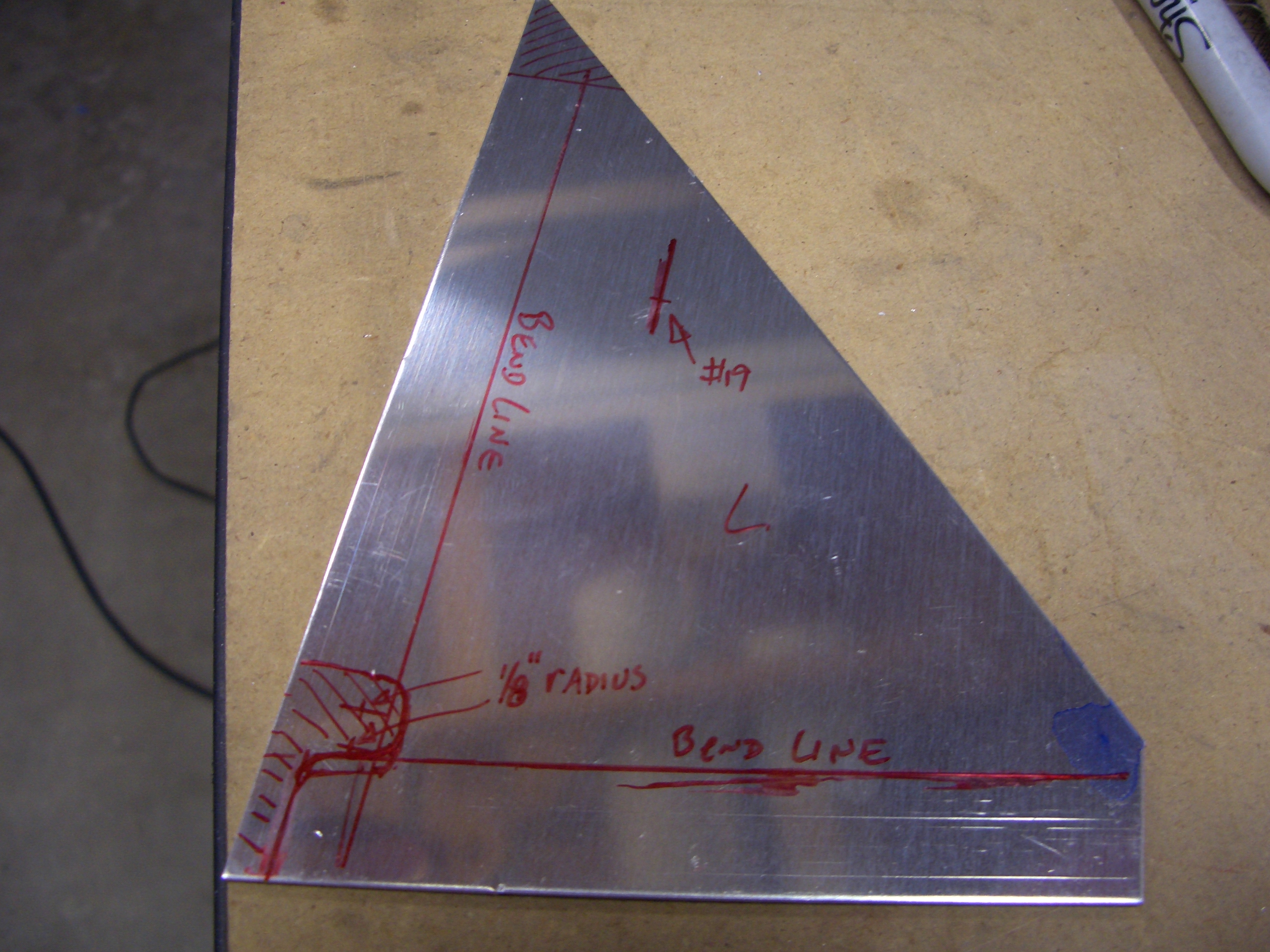
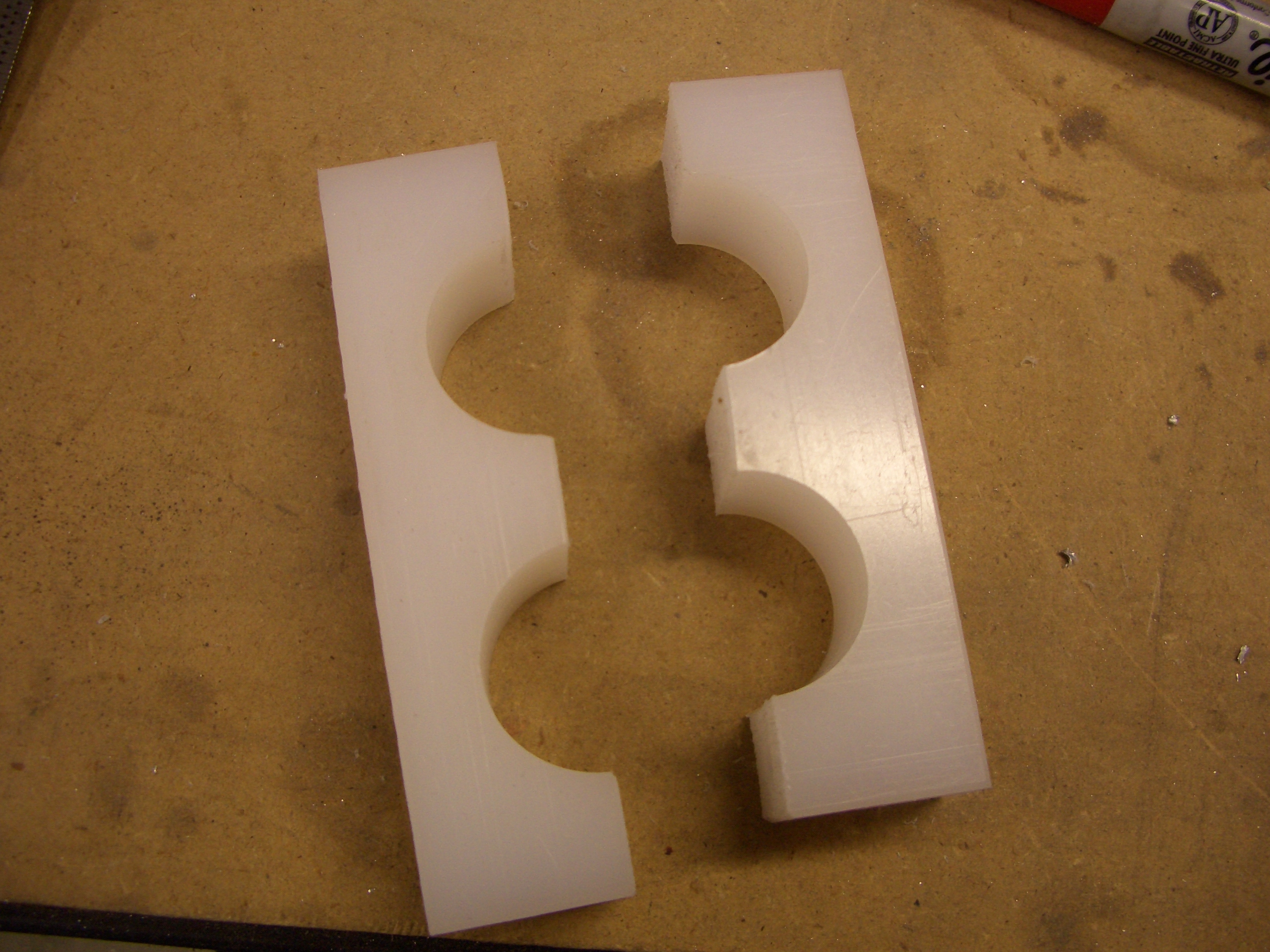
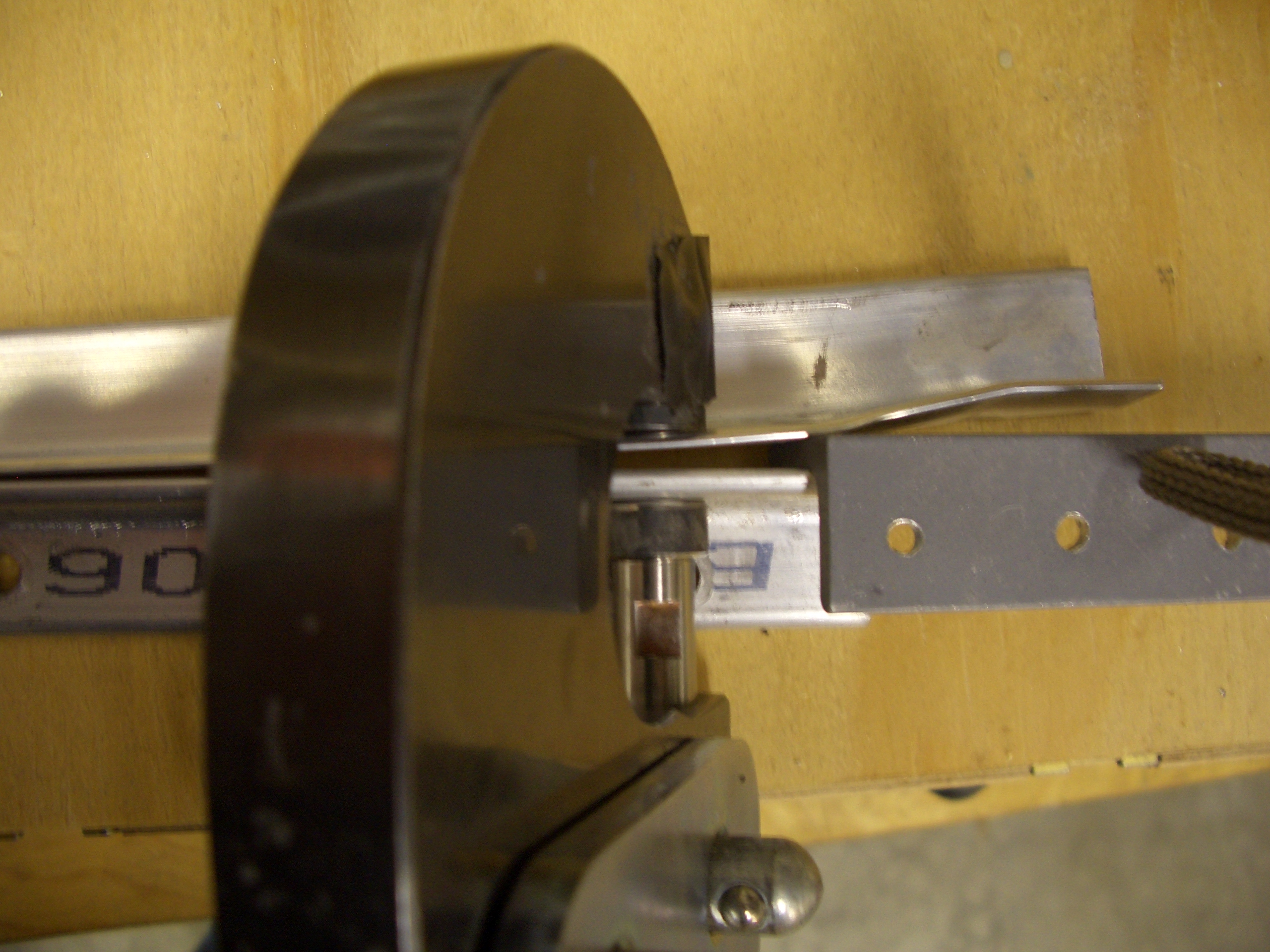
To correct this, I laid a piece of scrap 1/8″ angle stock (twice the thickness of the stiffener so it wouldn’t bend) against the side of the skin stiffener and inserted a second piece of scrap at the apex of the bend.

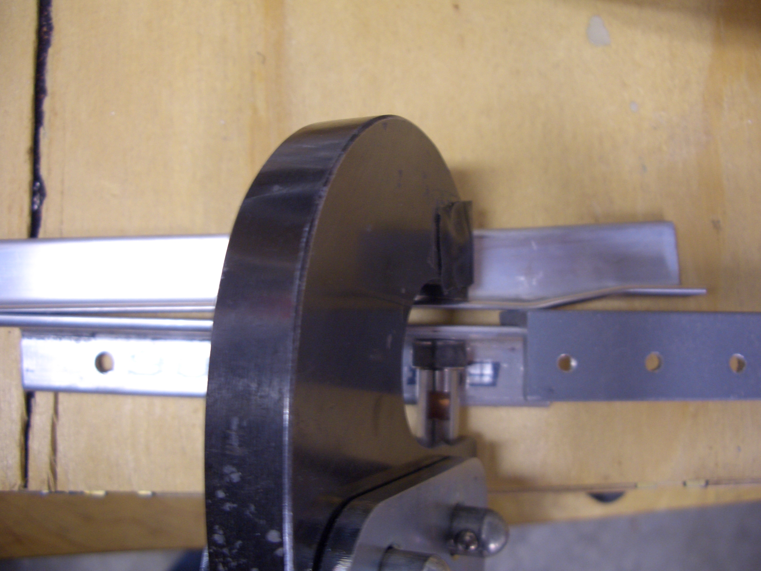
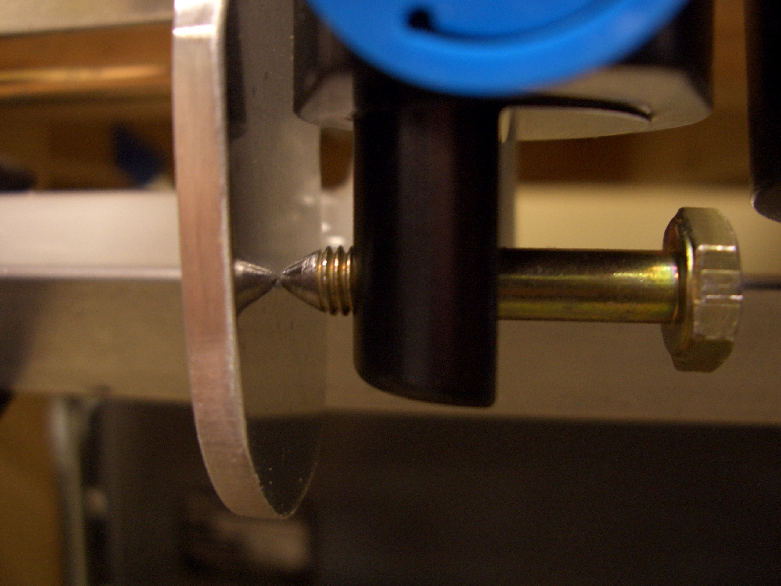
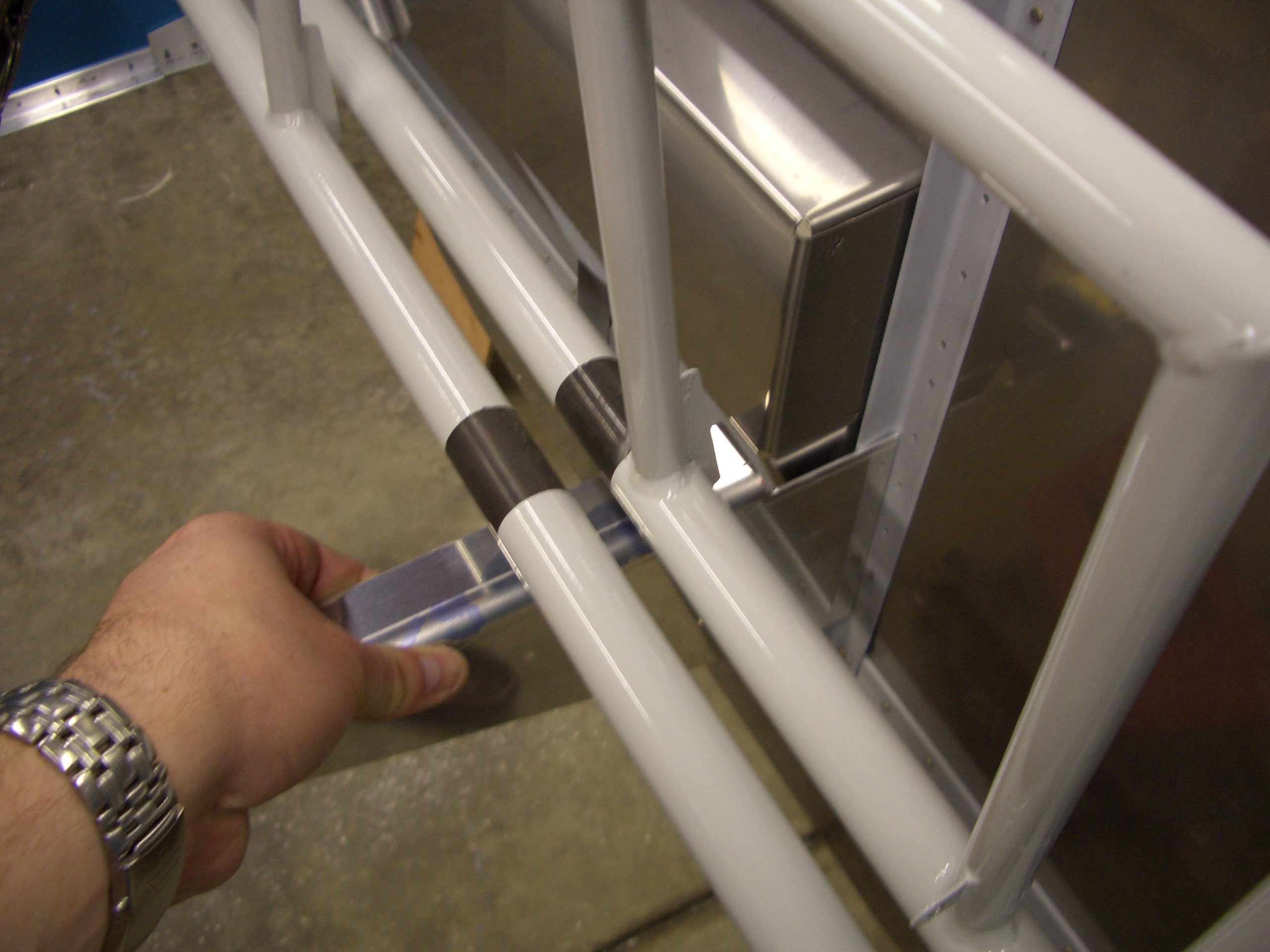
I then used my hand squeezer to slightly overbend the leg of the angle.  It’s easy to overdo it here, so watch out.

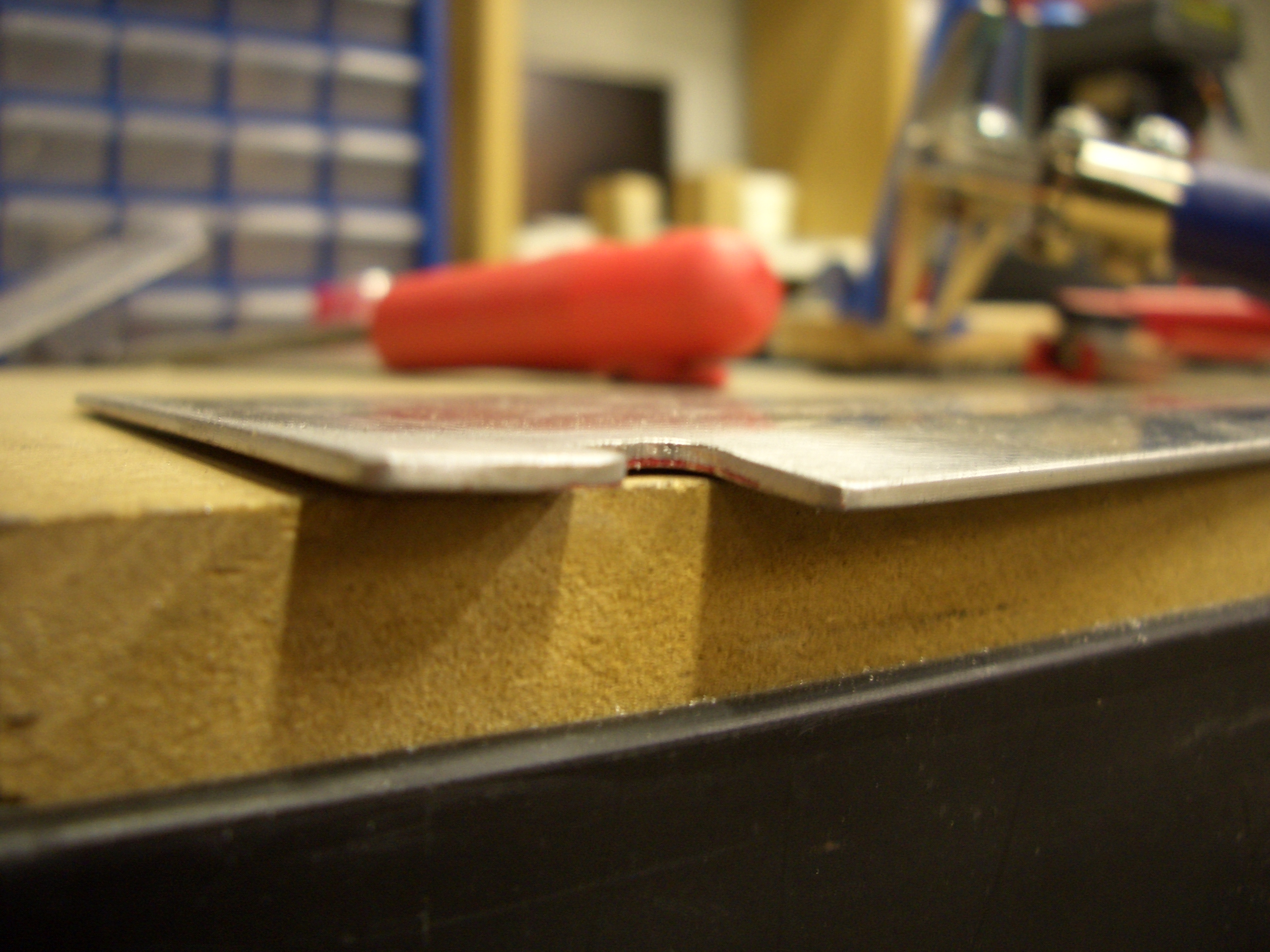
Now the leg of the angle is perfectly straight right up to the apex of the bend.

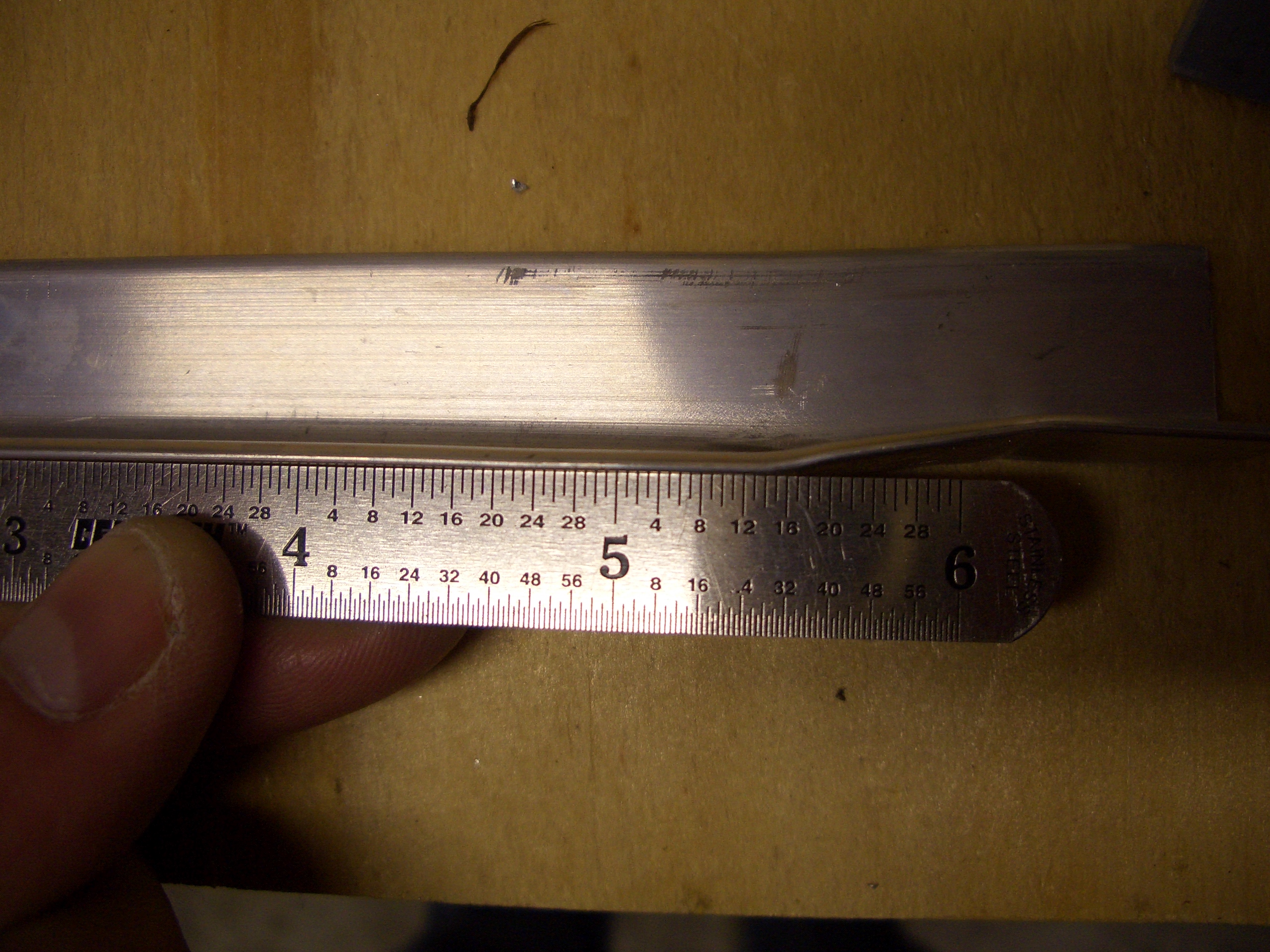
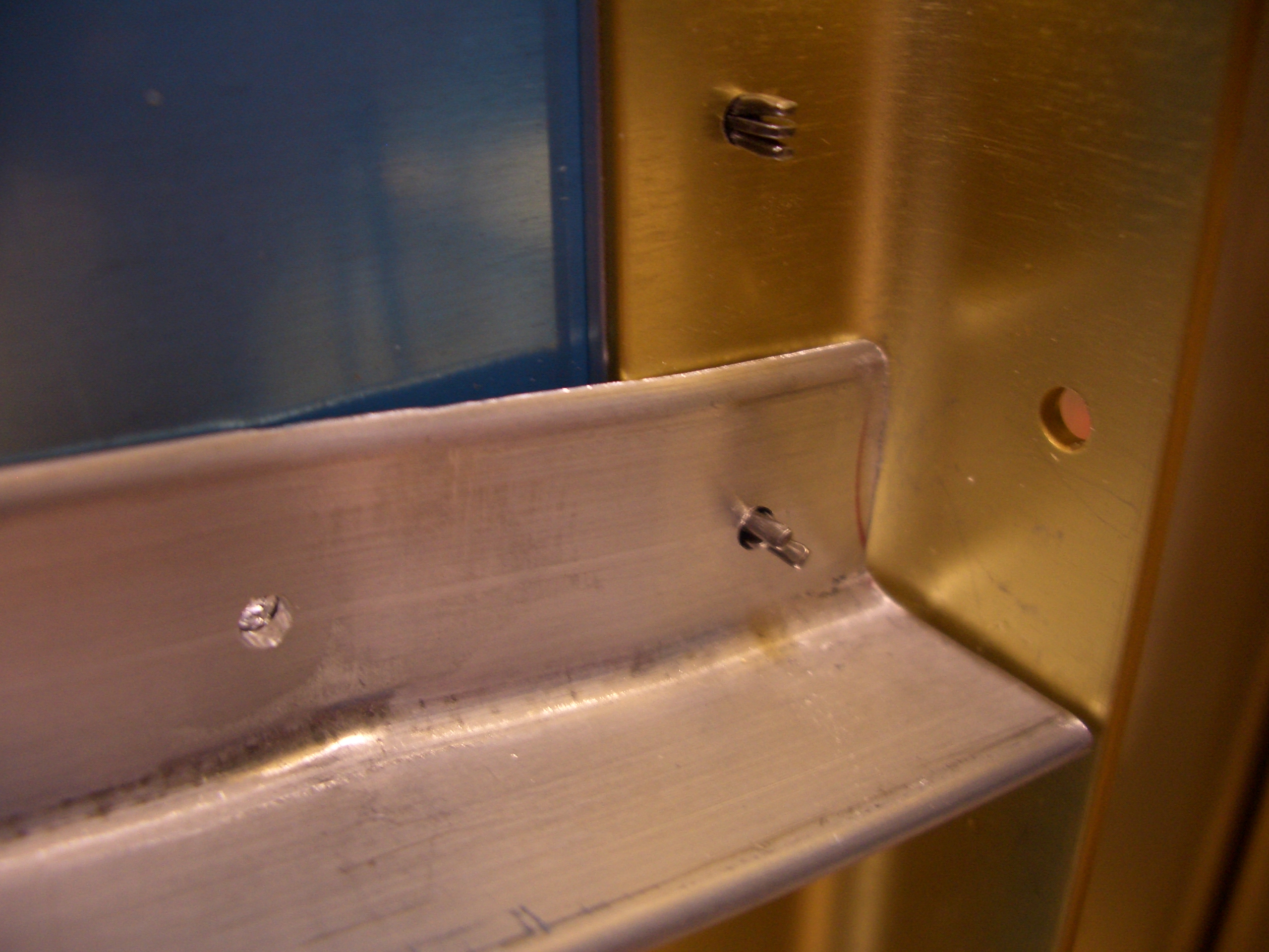
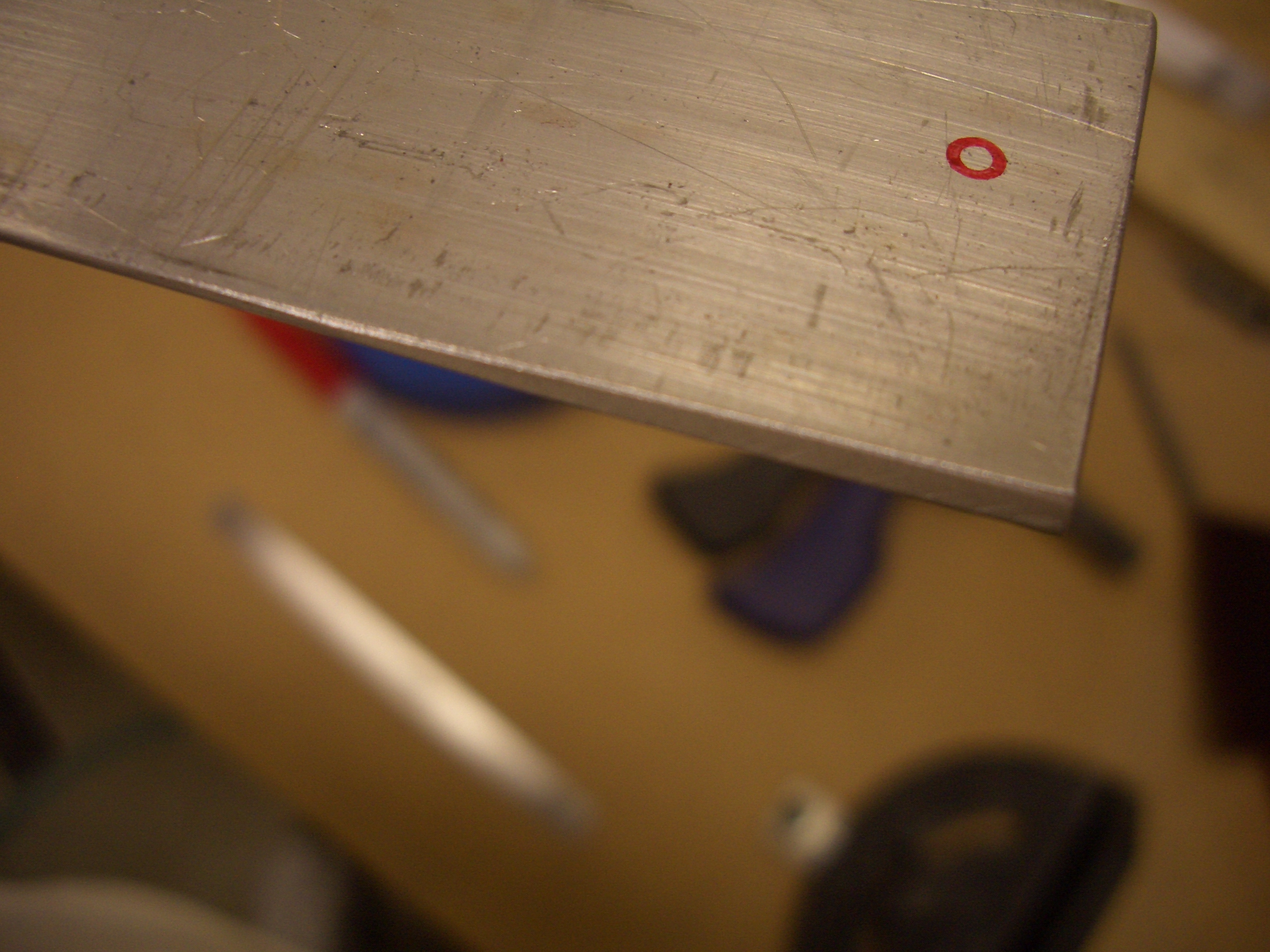
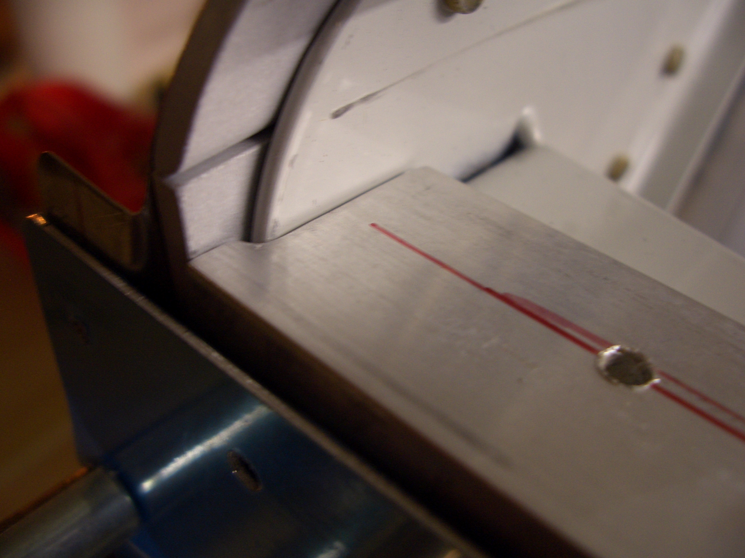
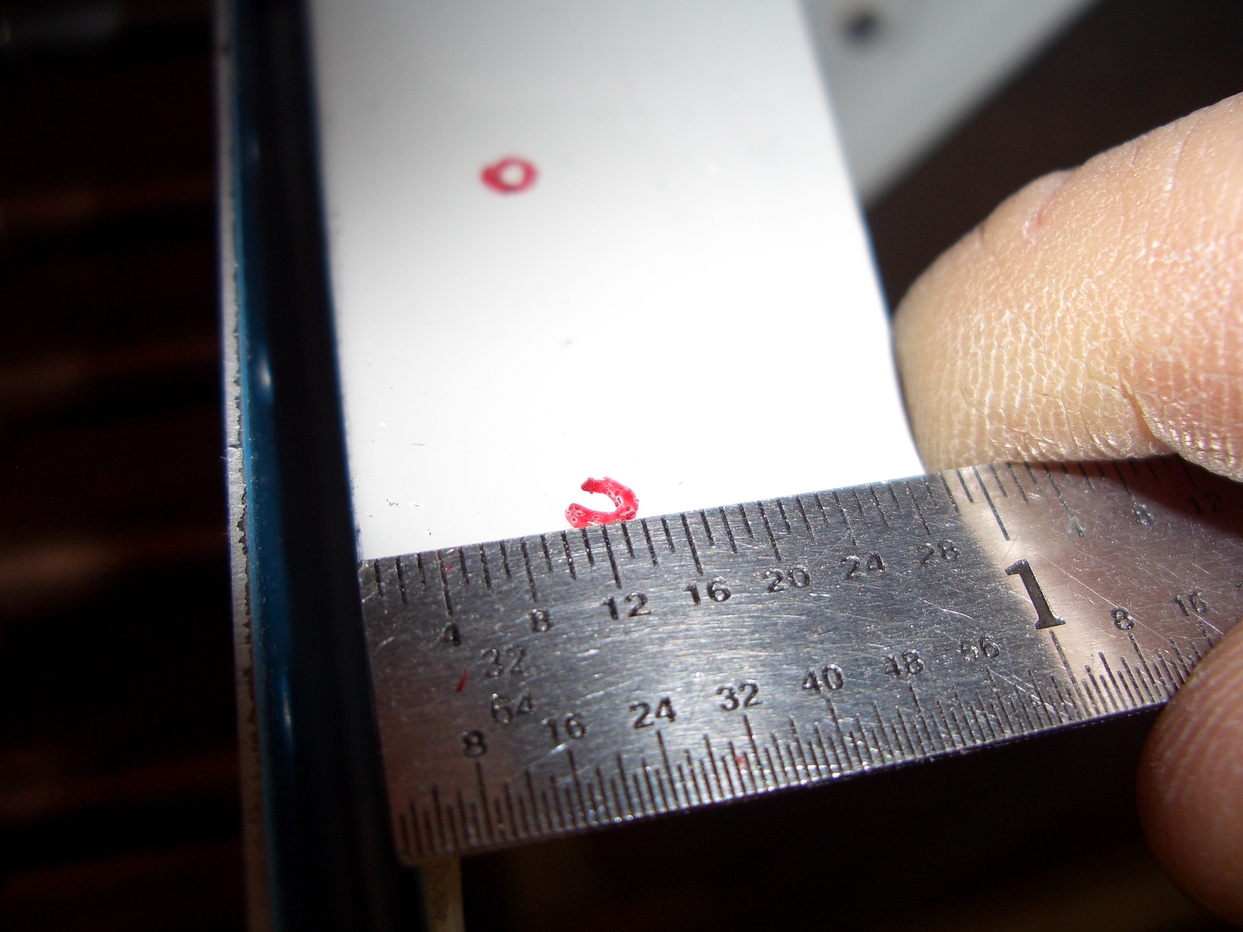
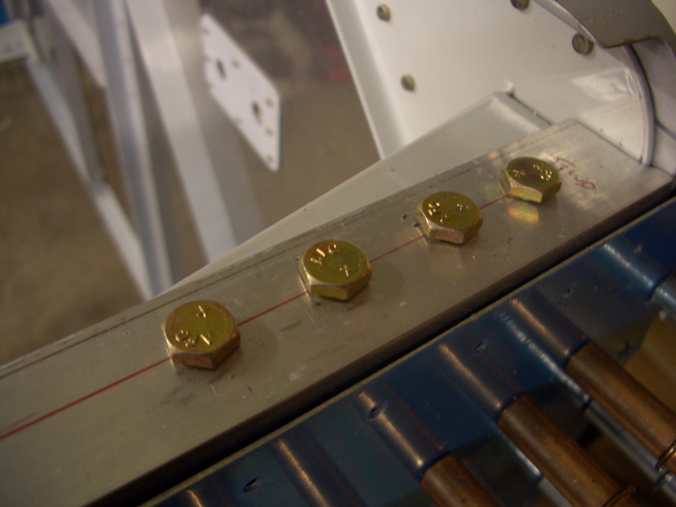
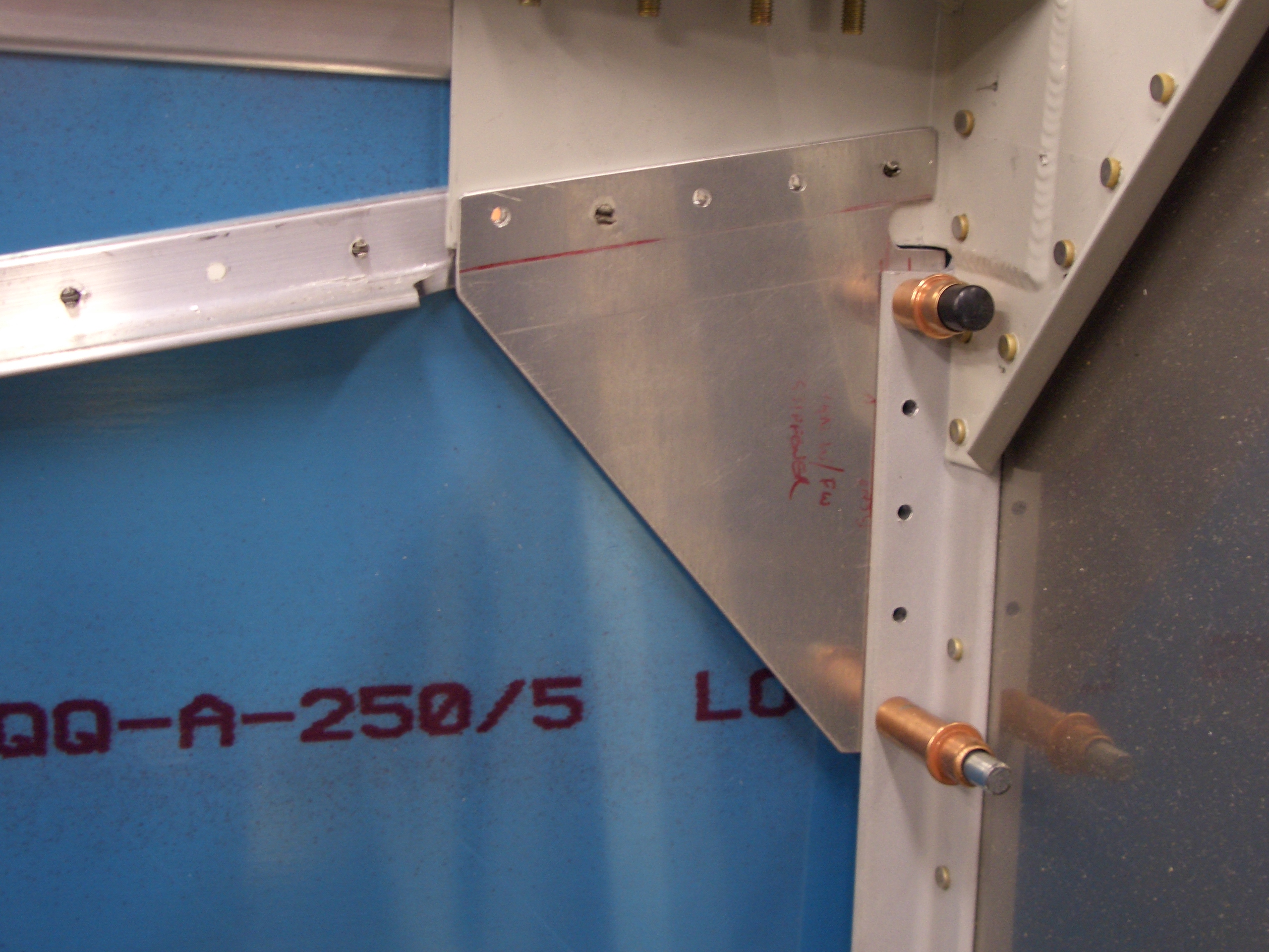
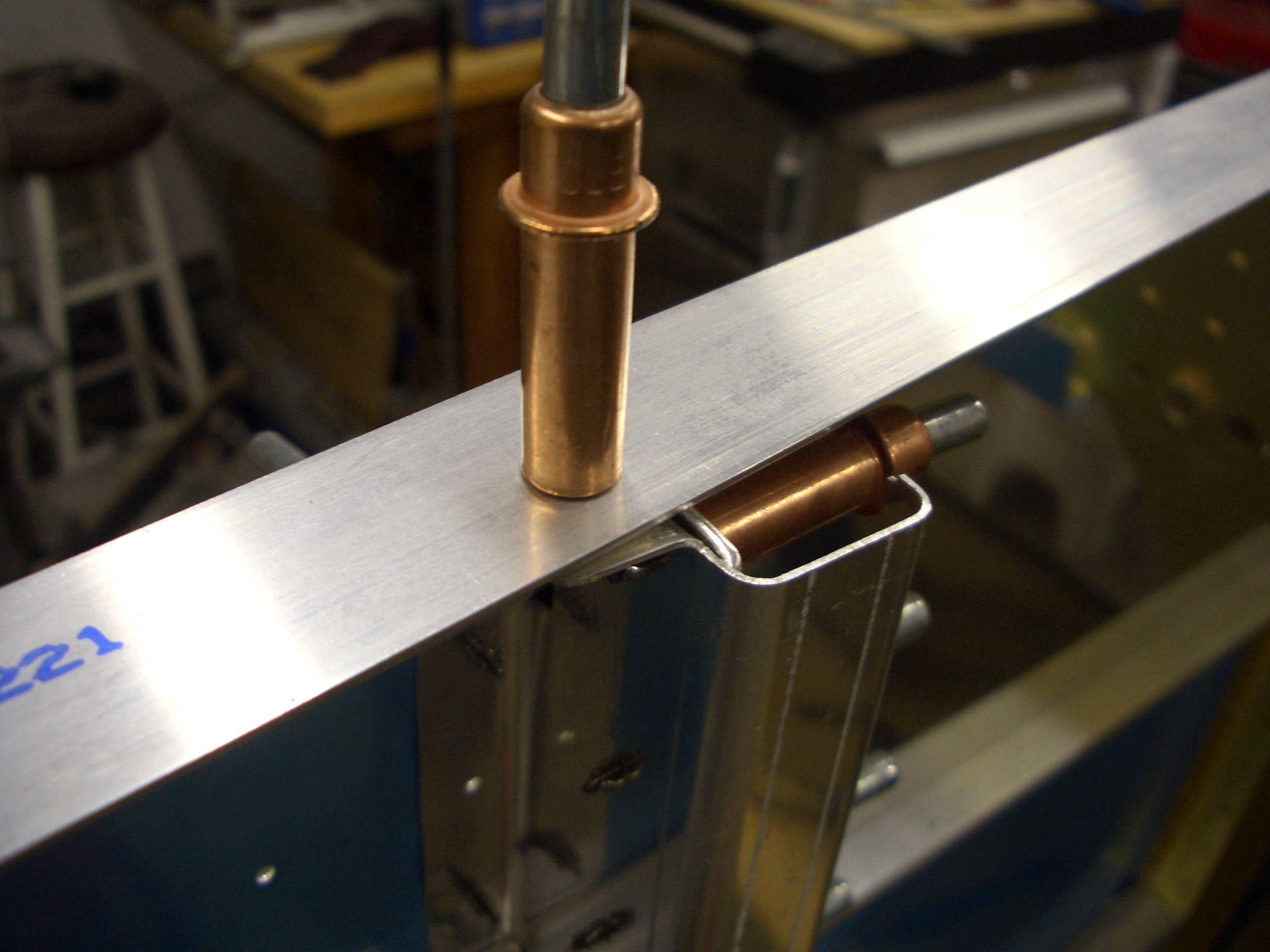
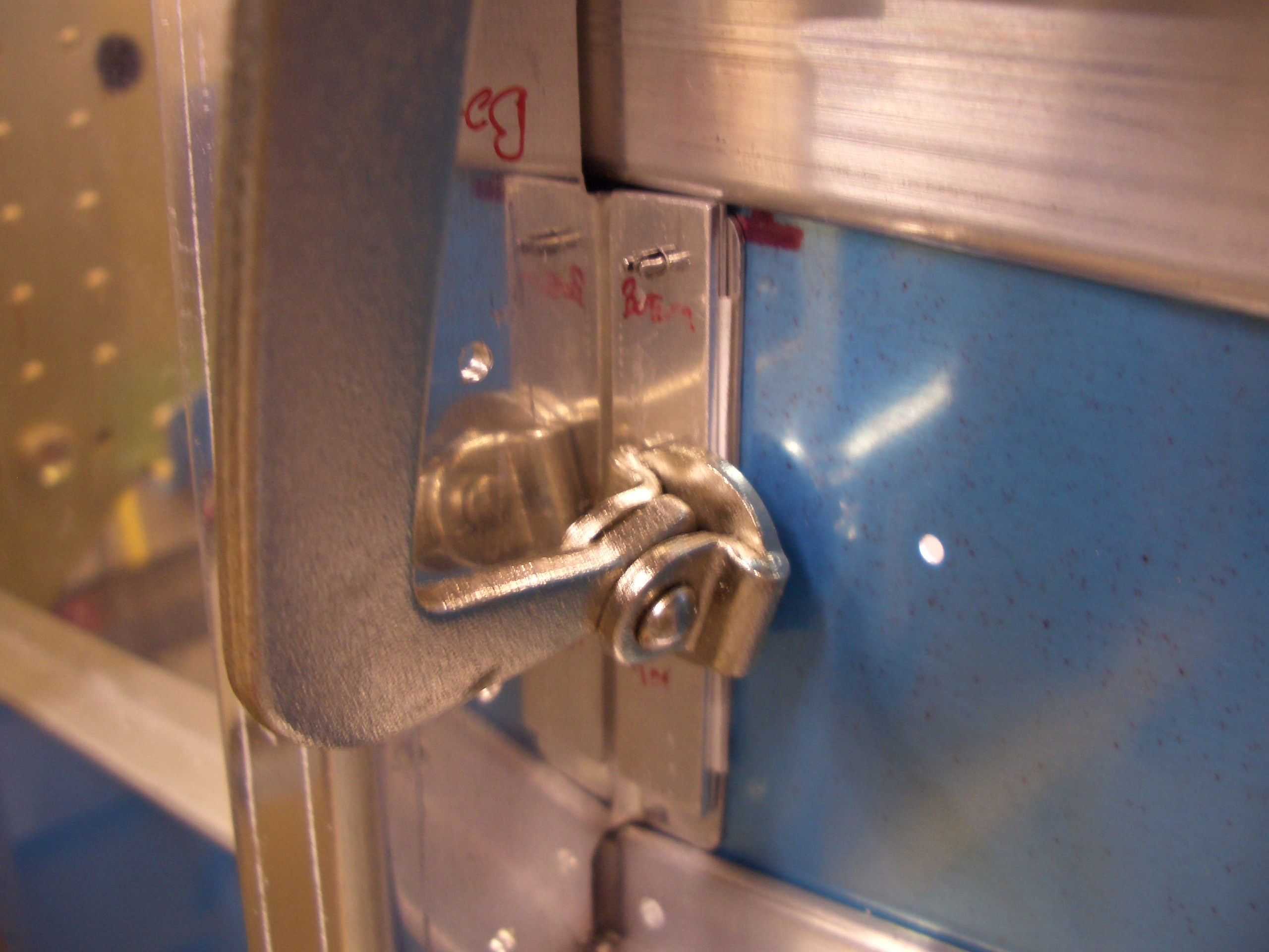
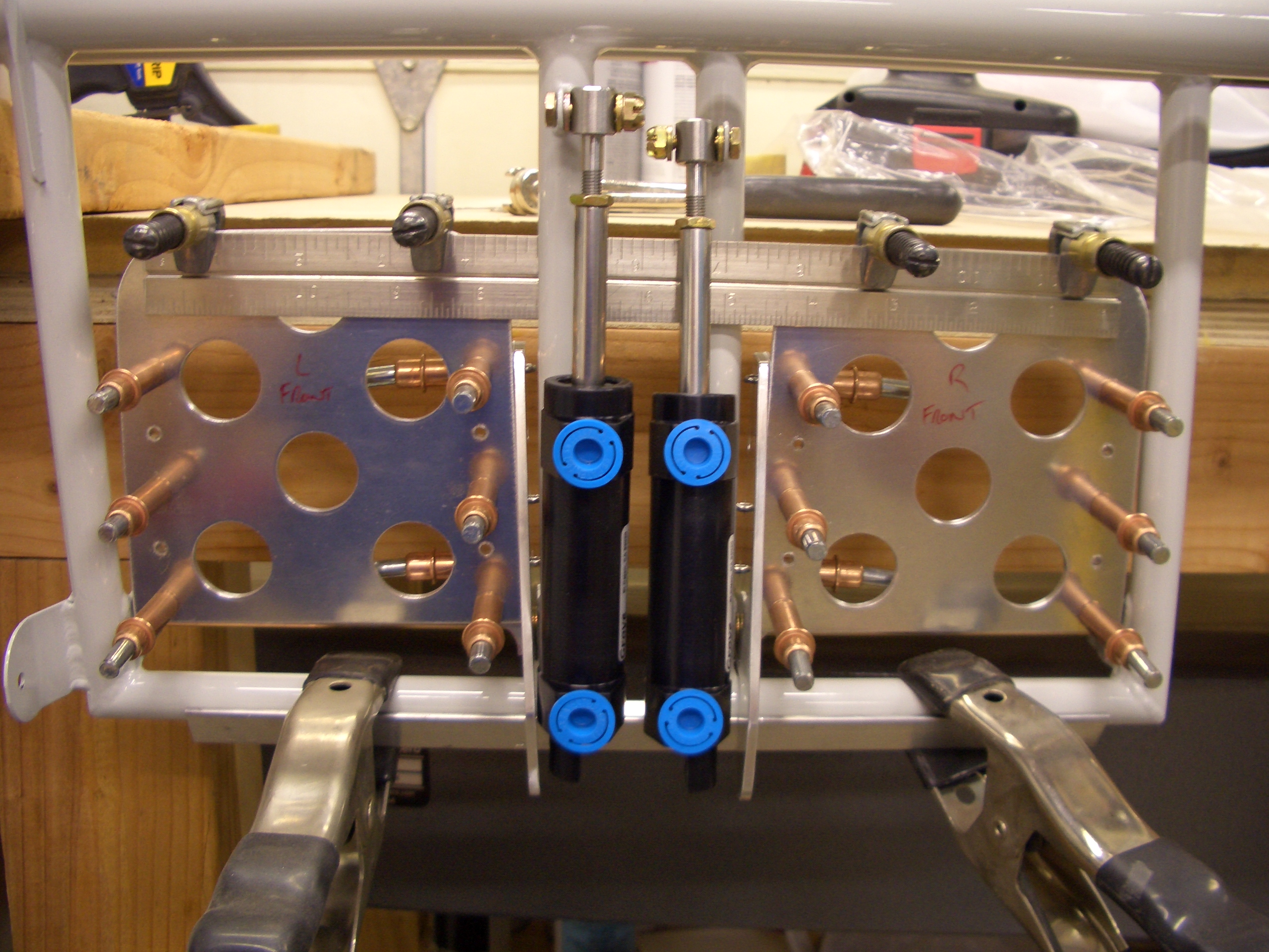
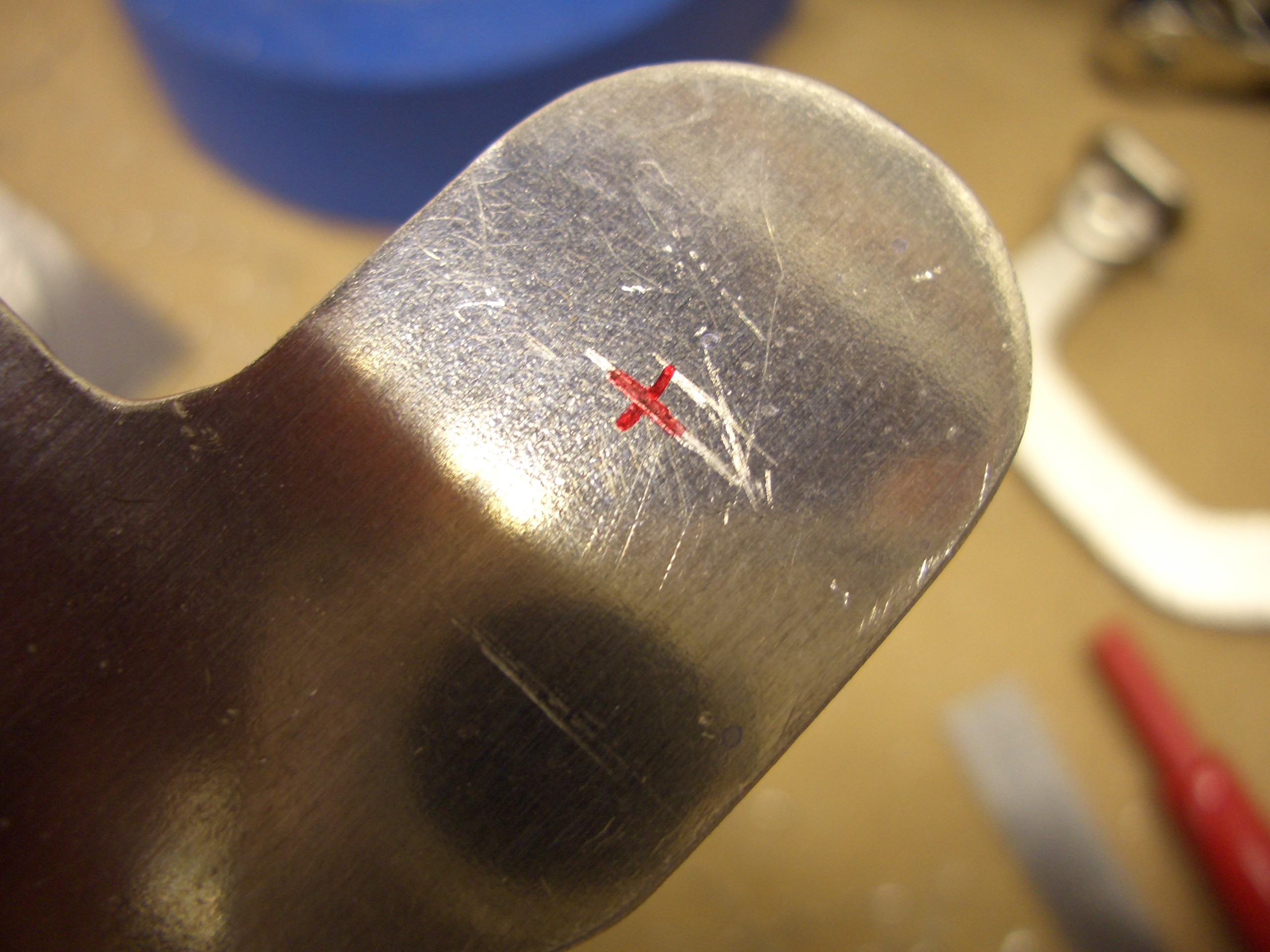
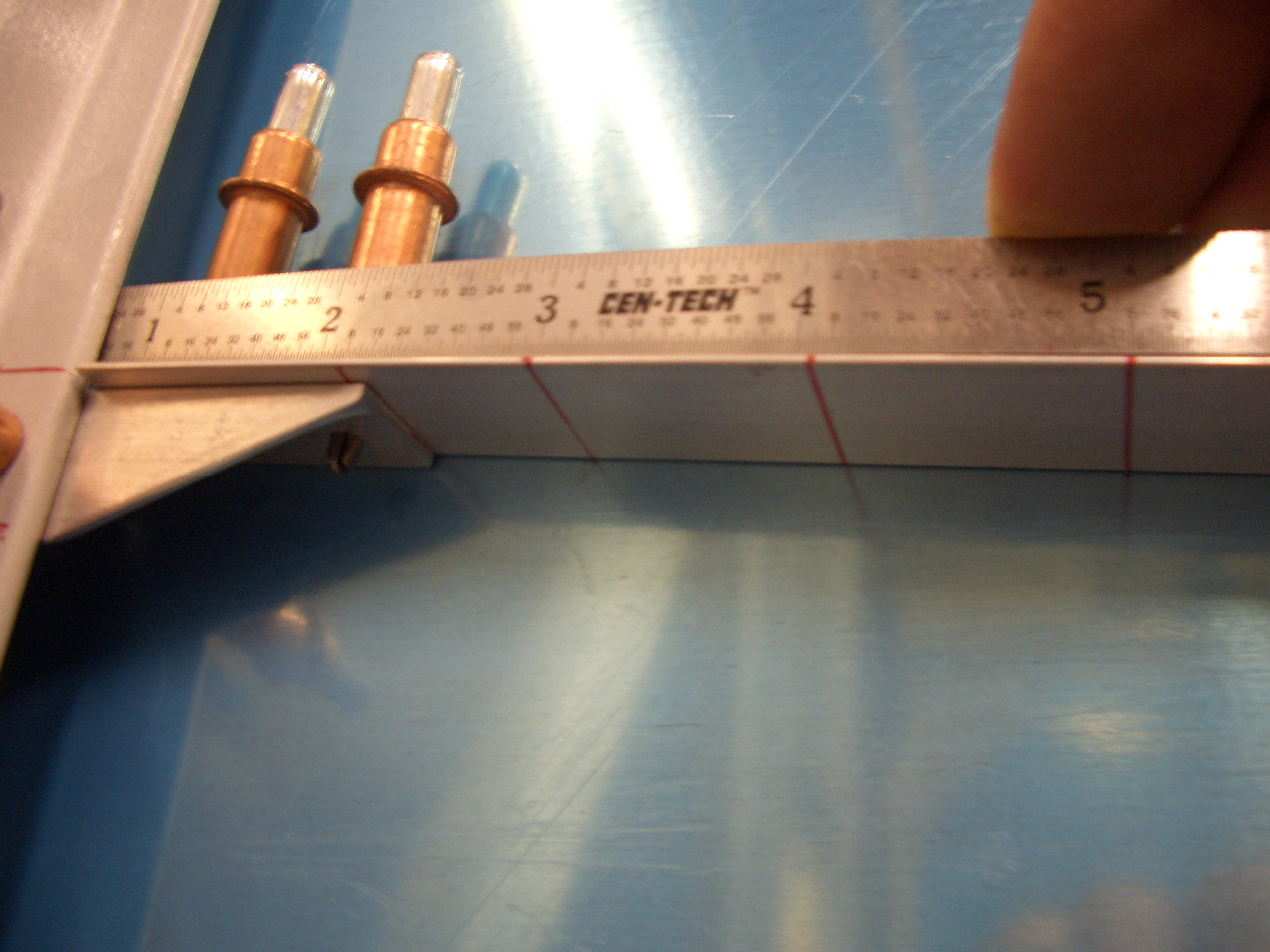
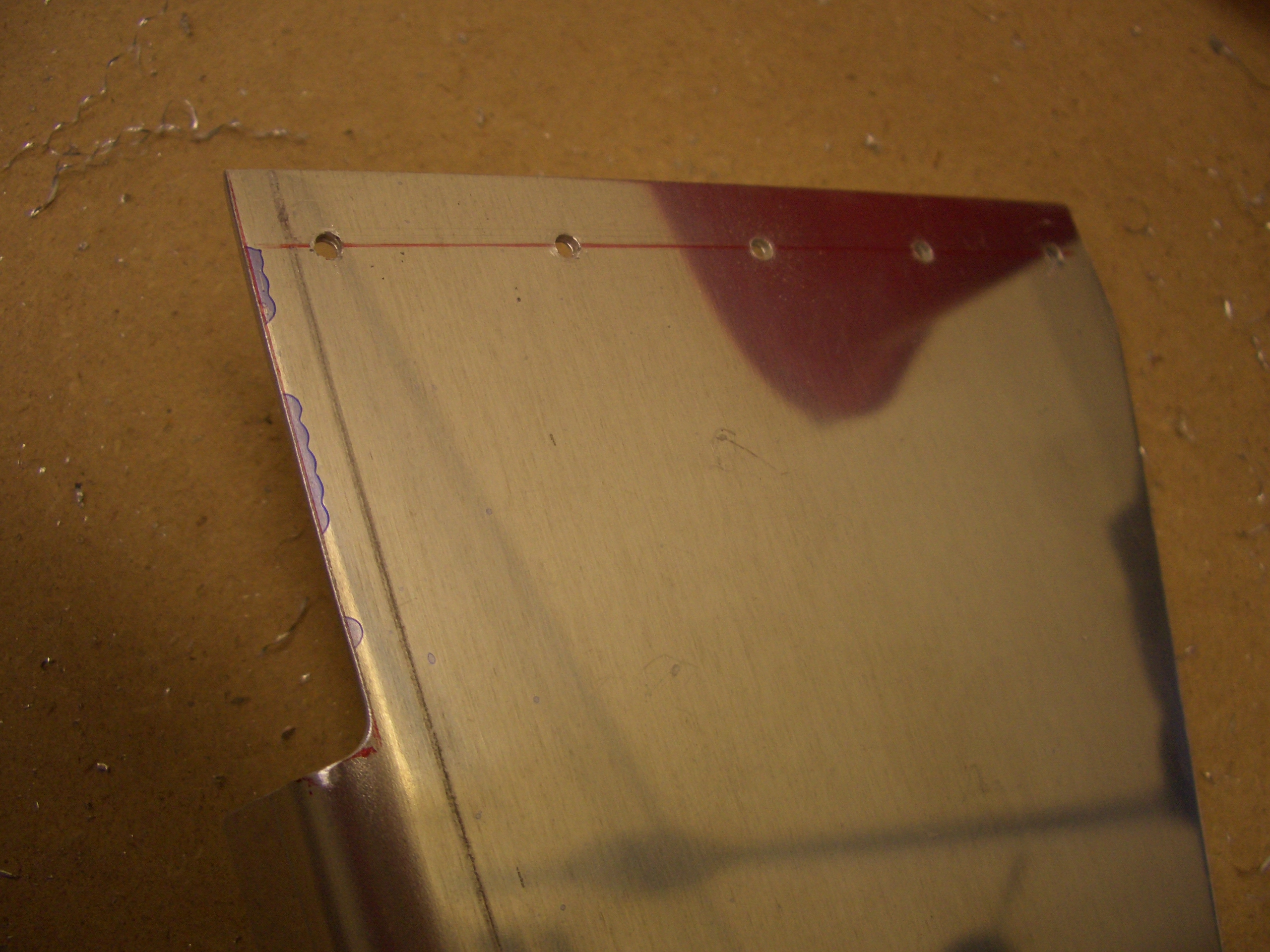
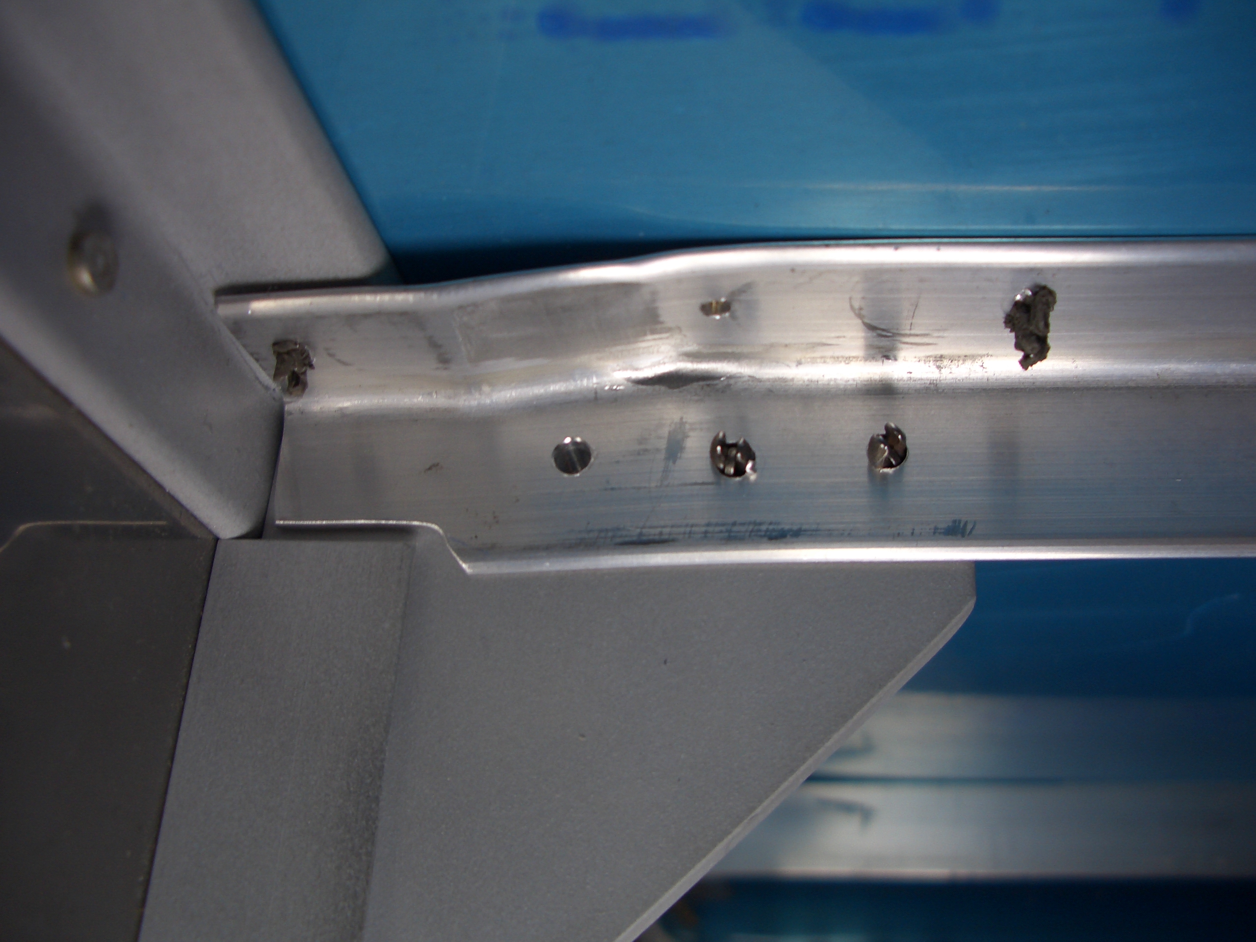
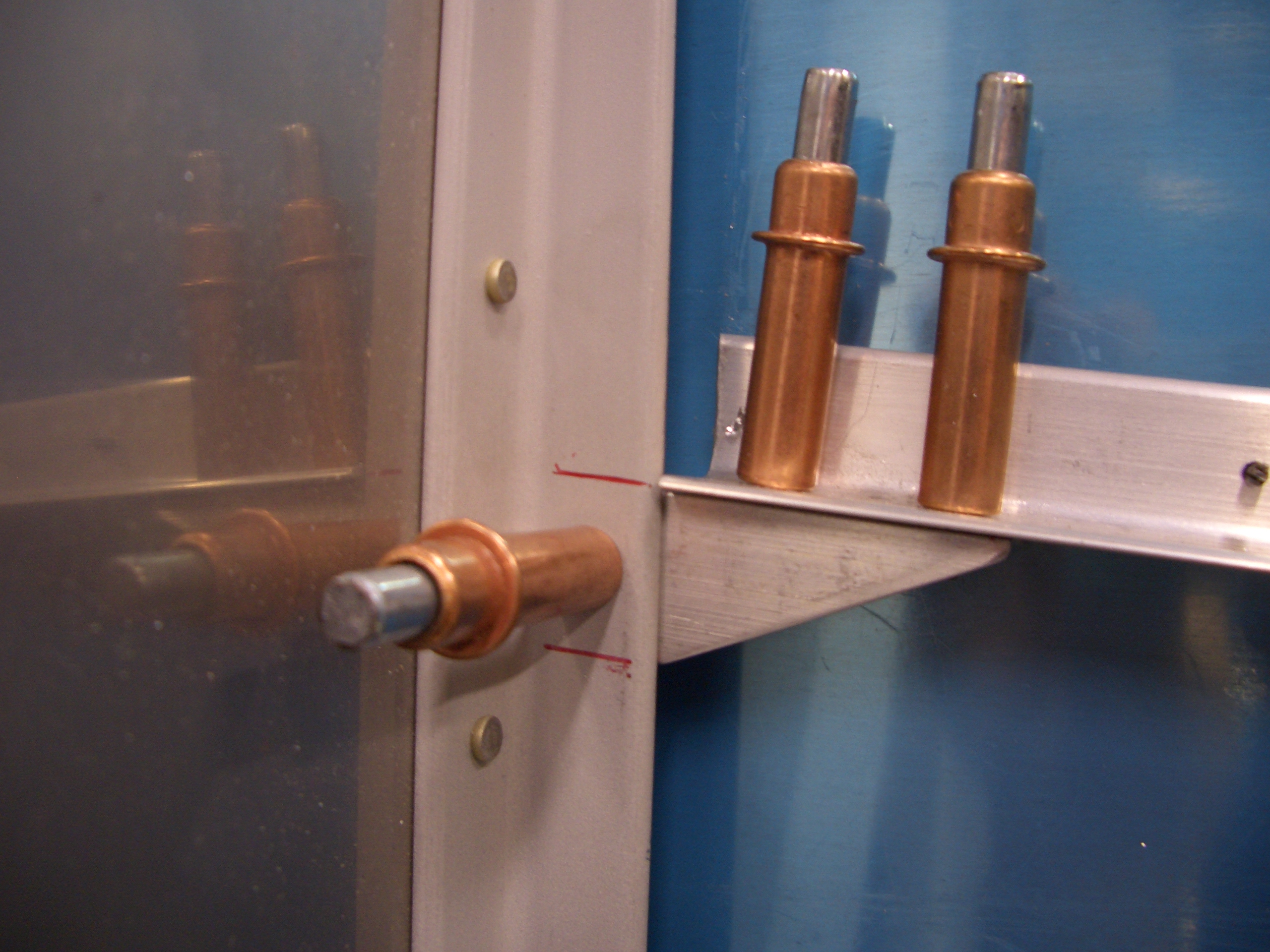
After trimming both ends of the stiffener, I installed it and marked the forward hole to double check edge distance on this rivet (it’s the left hole in this picture).  It turned out 1/32″ over 2d, so that’s perfect.

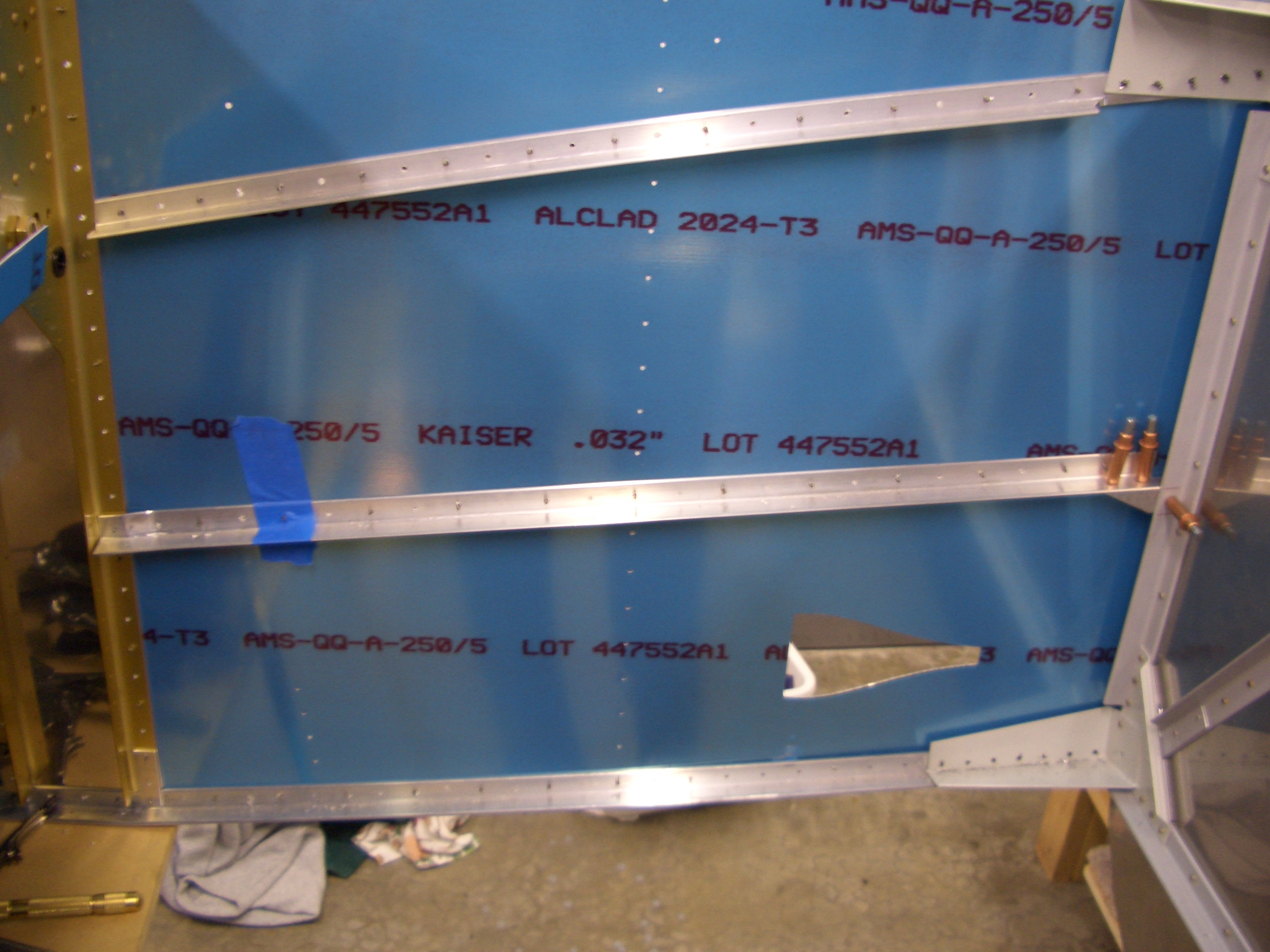
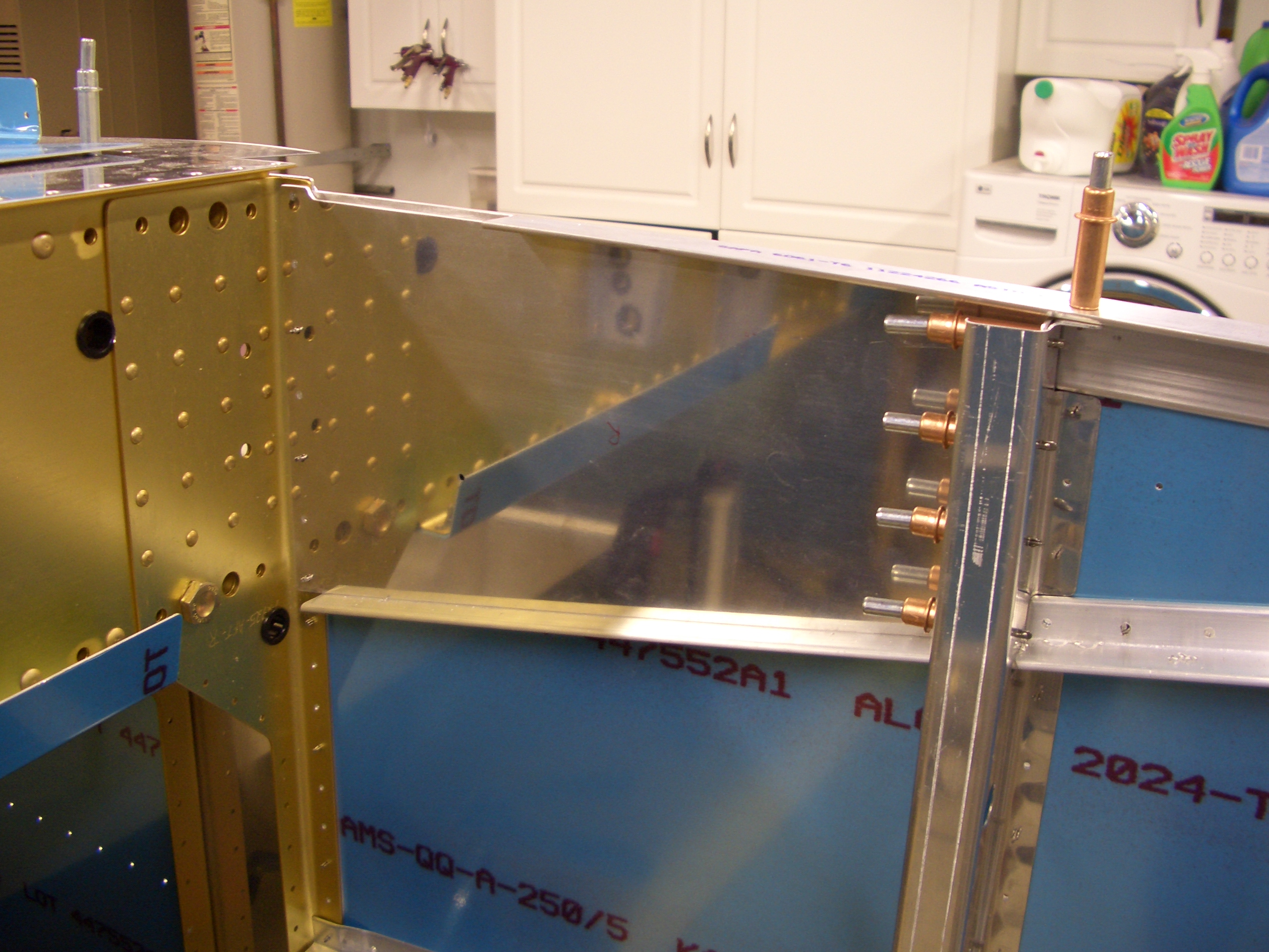
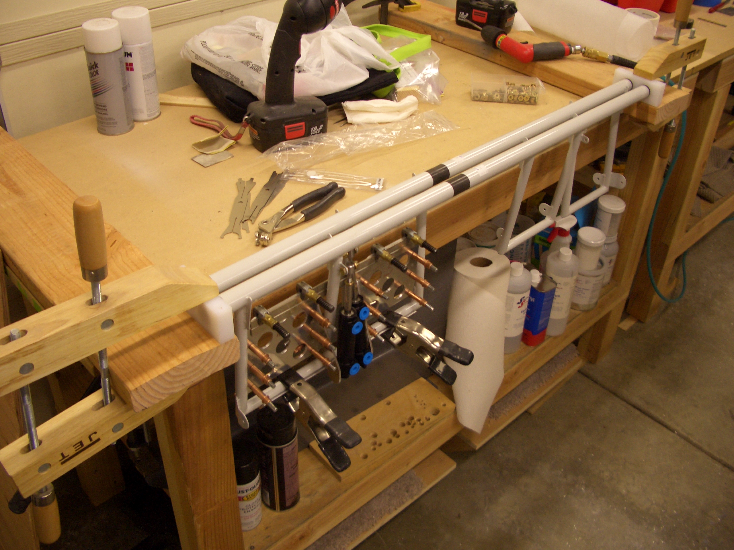
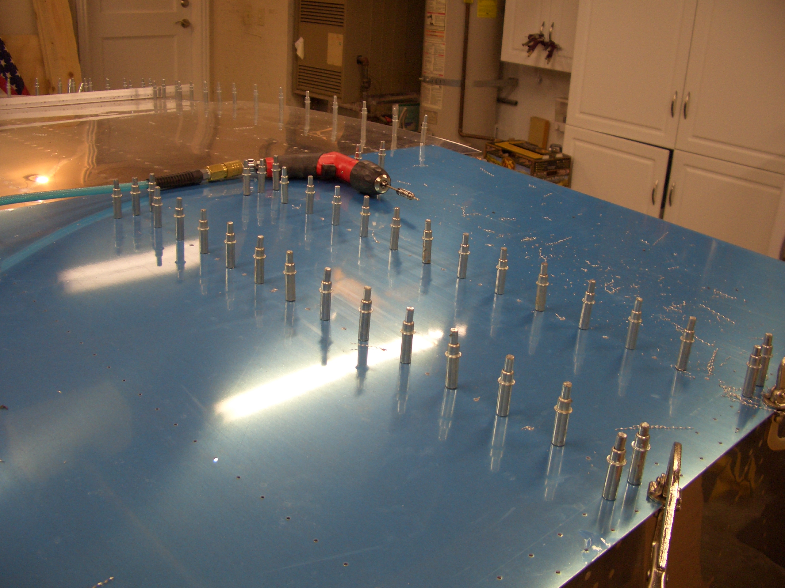
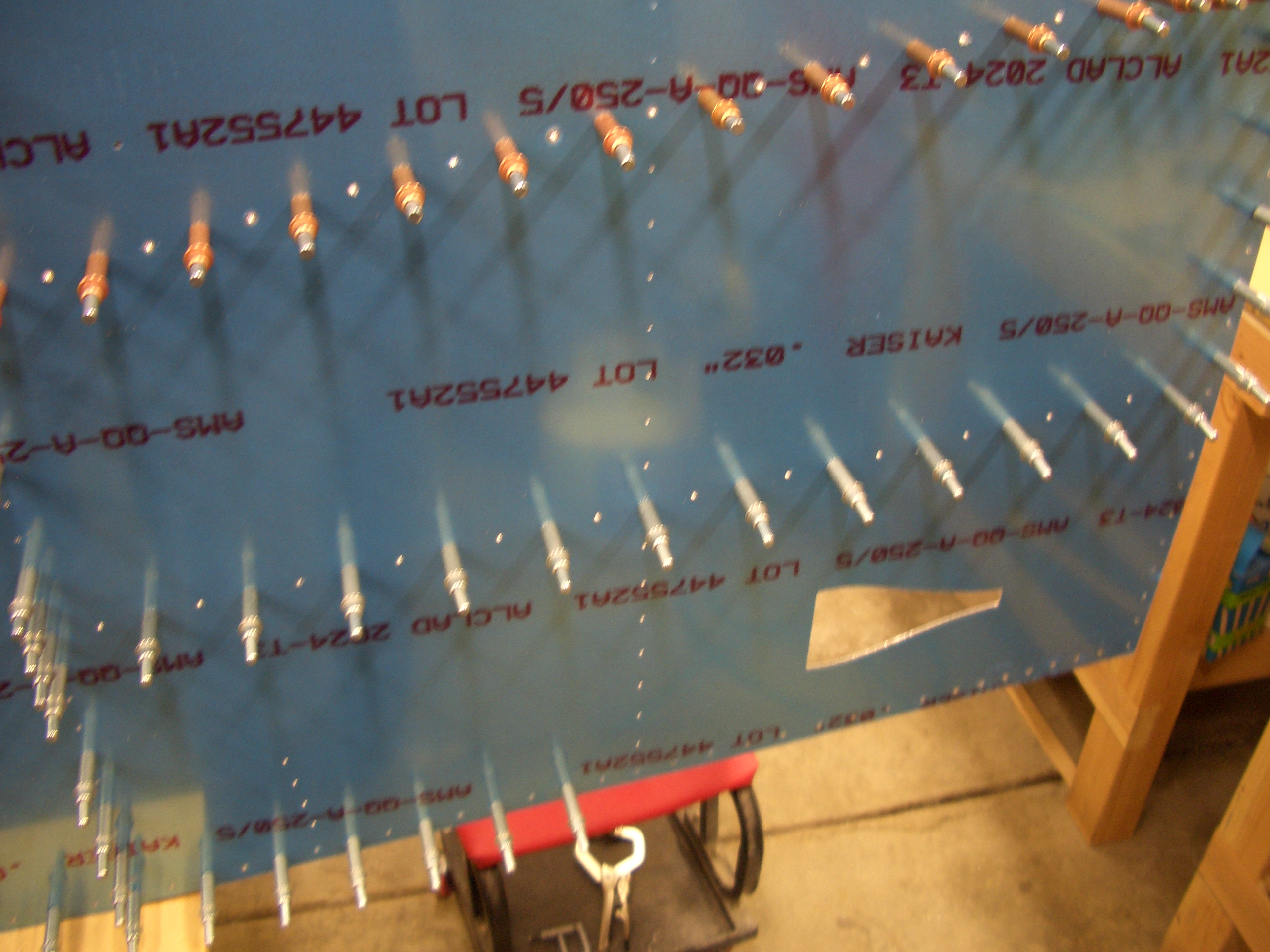
I match drilled the stiffener to the side skin.

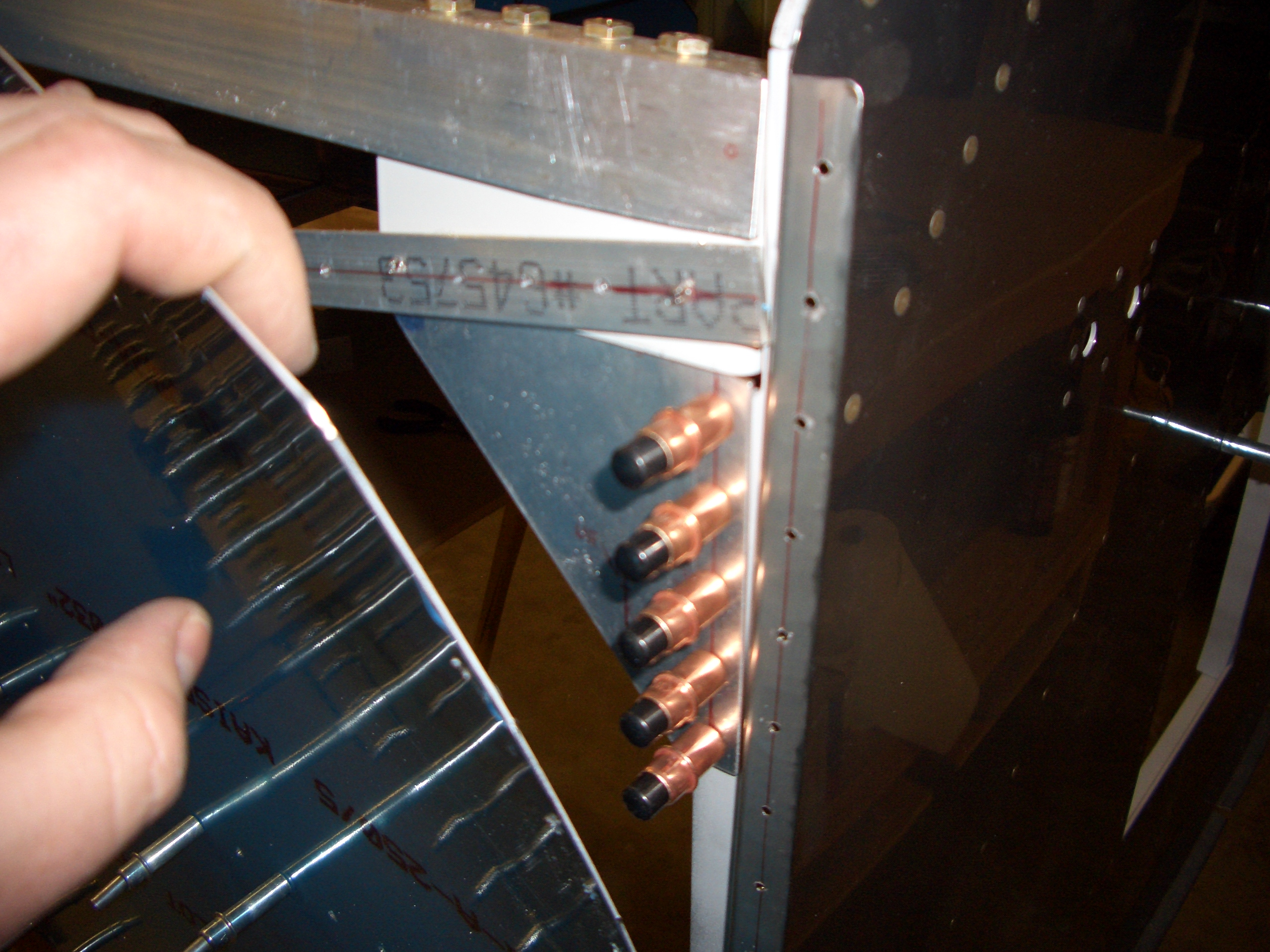
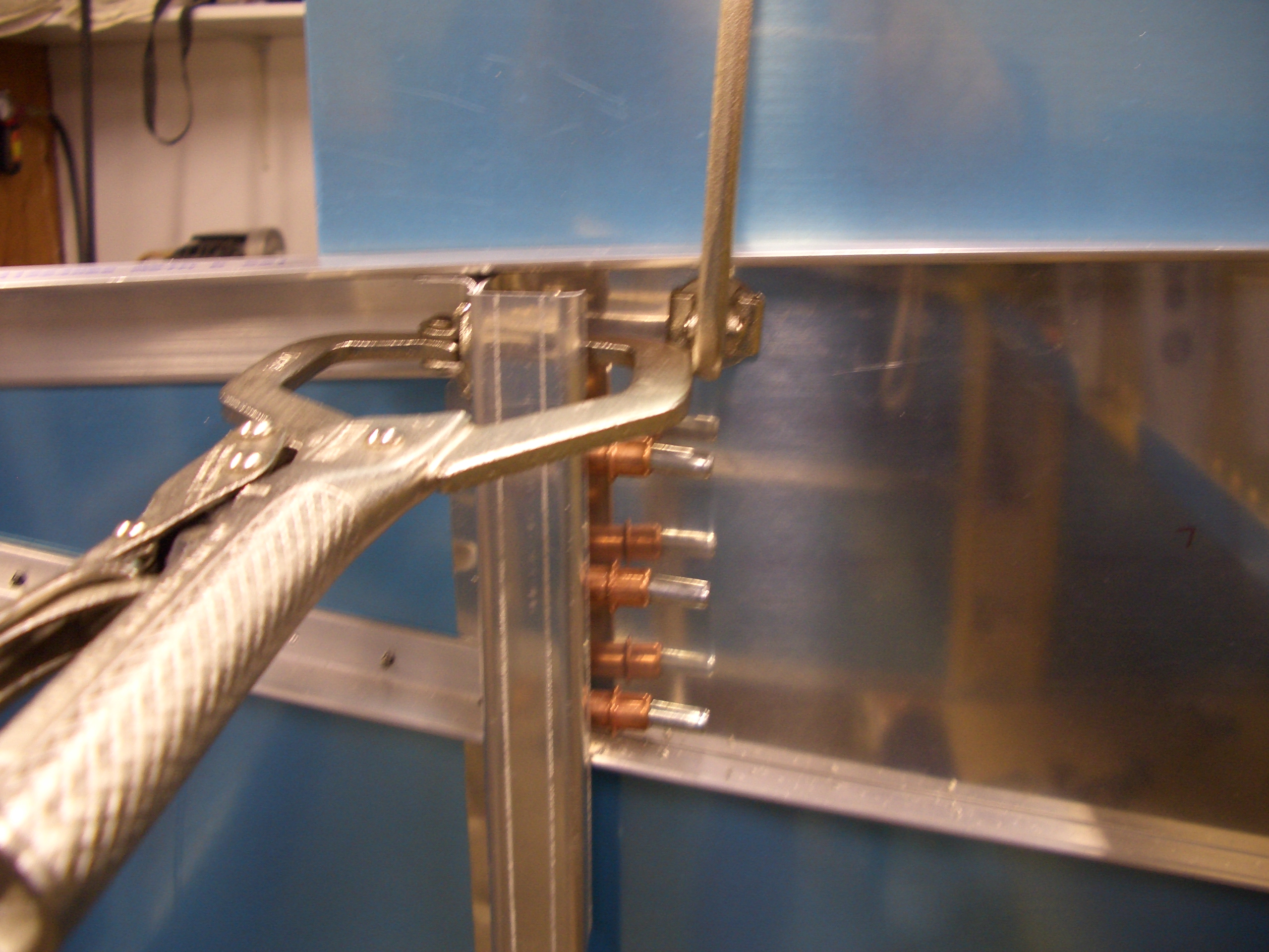
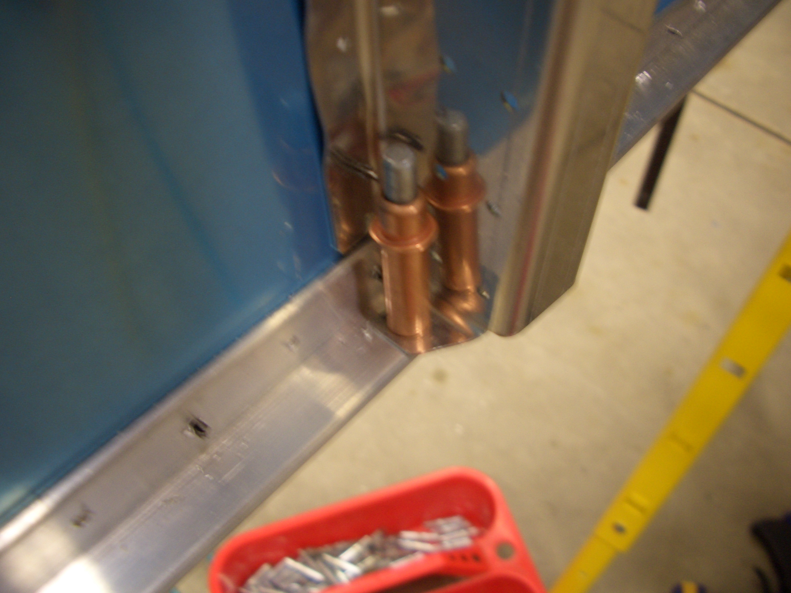
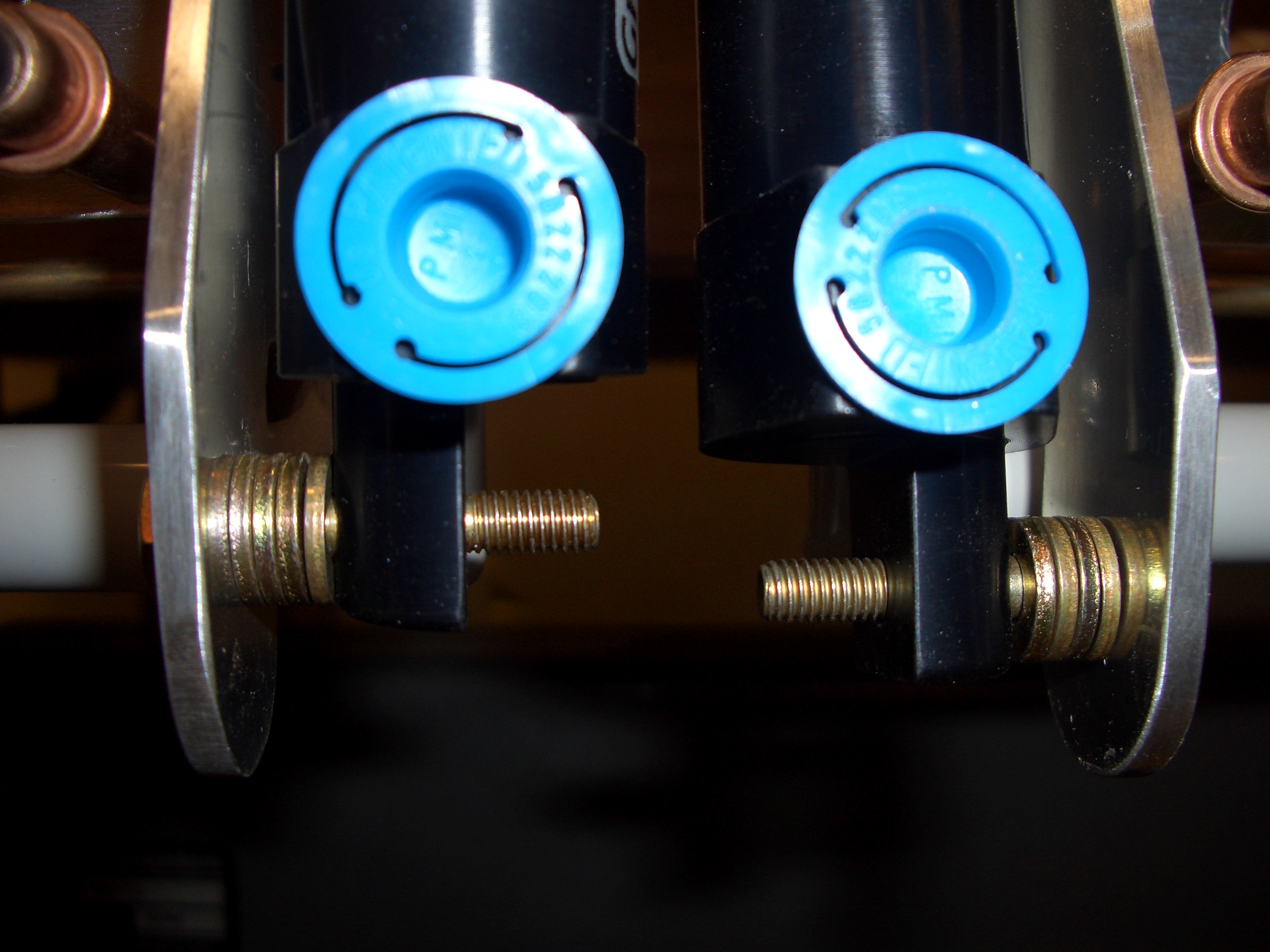
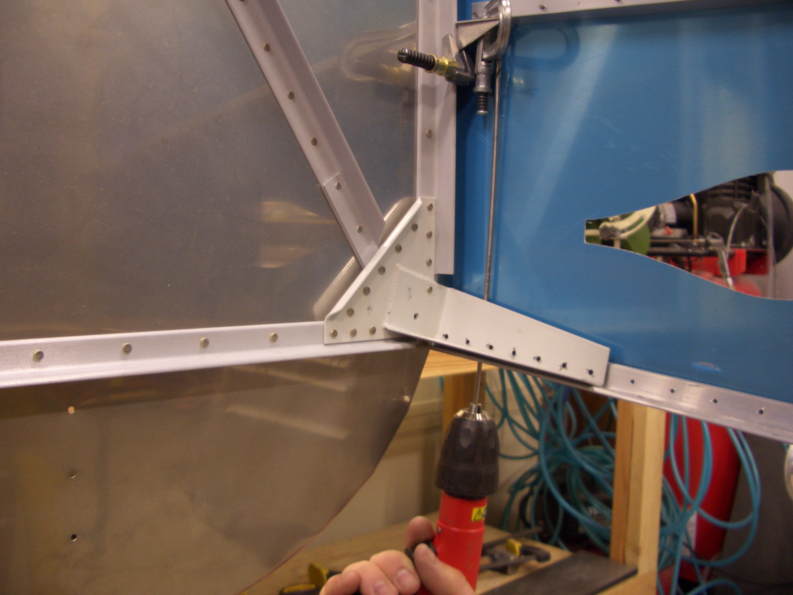
The I removed some of the clecos on the side skin so that I could get a 12″ drill bit in here to match drill the angle clips to the side stiffener.

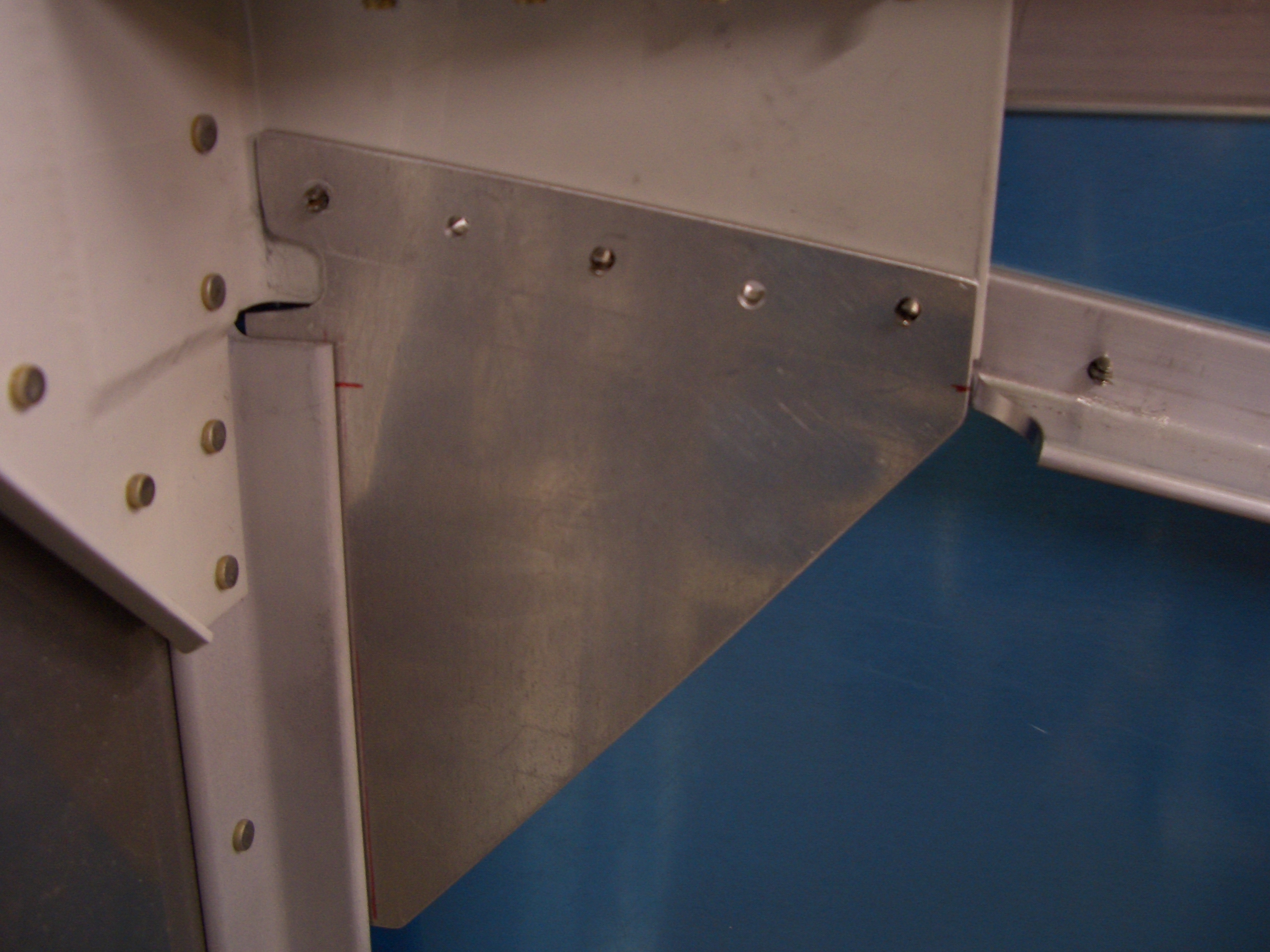
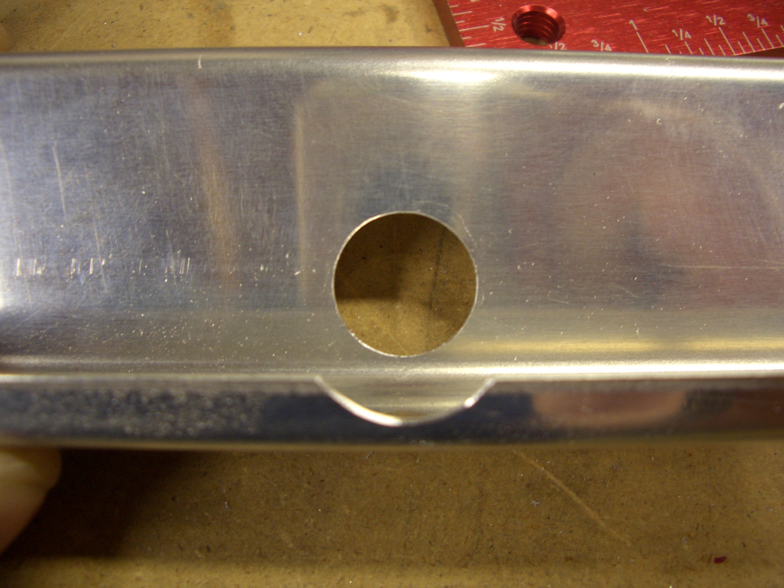
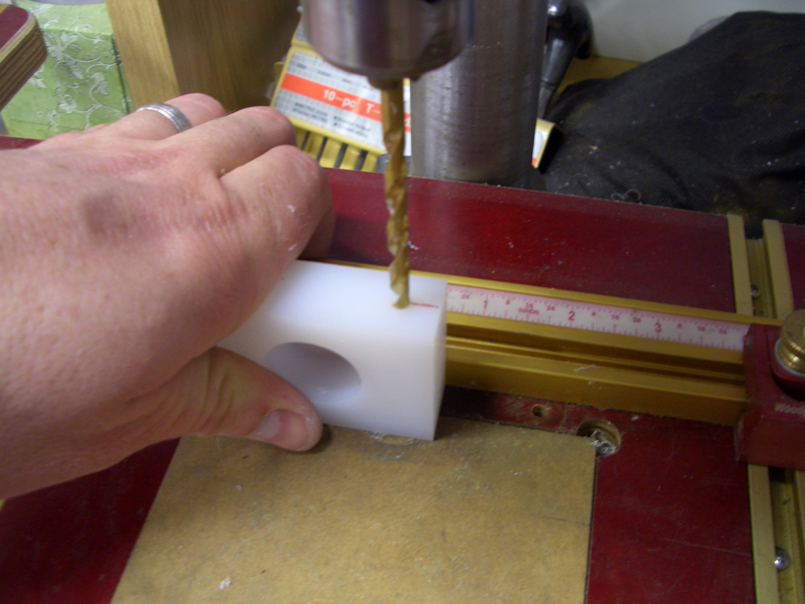
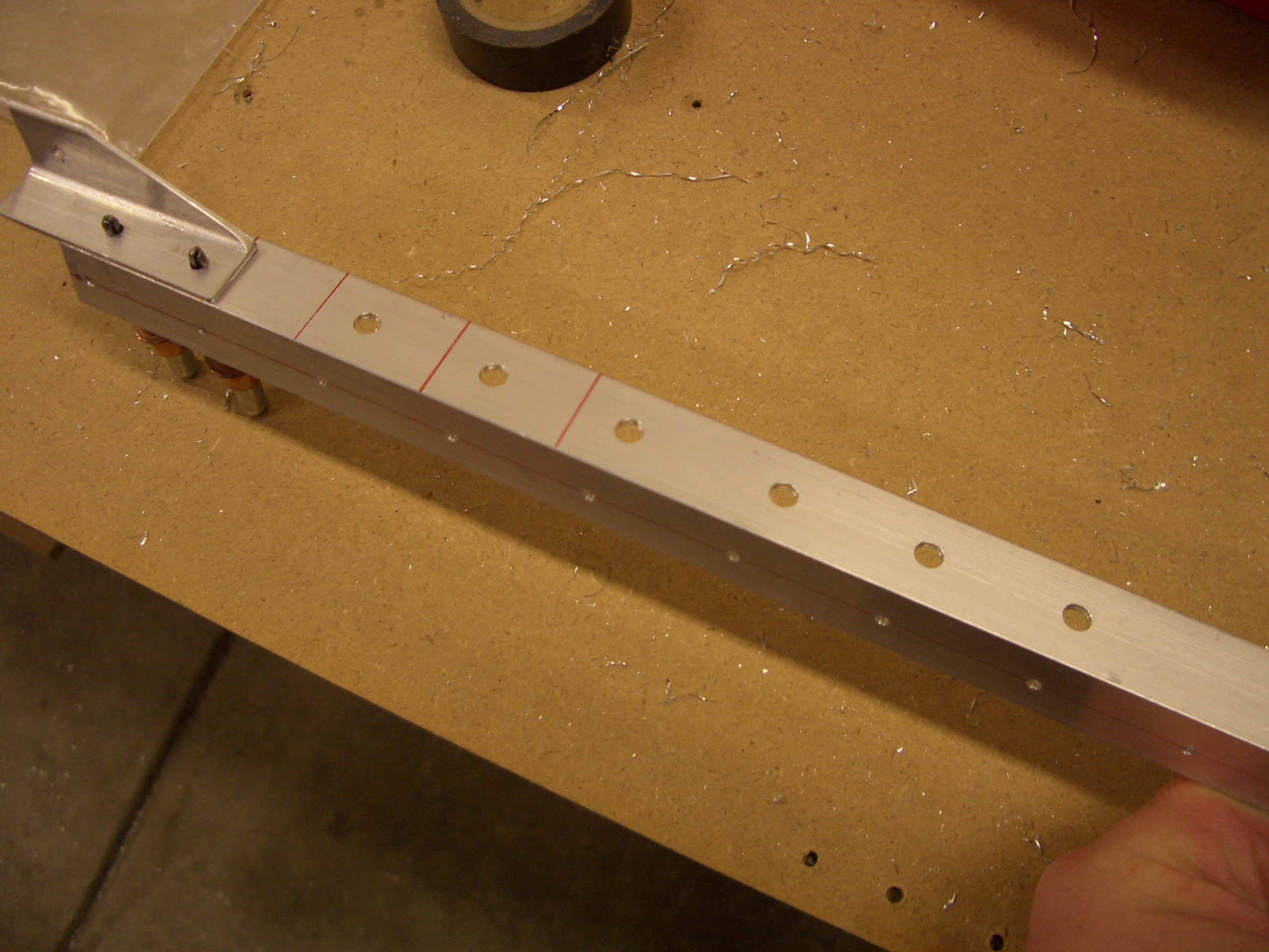
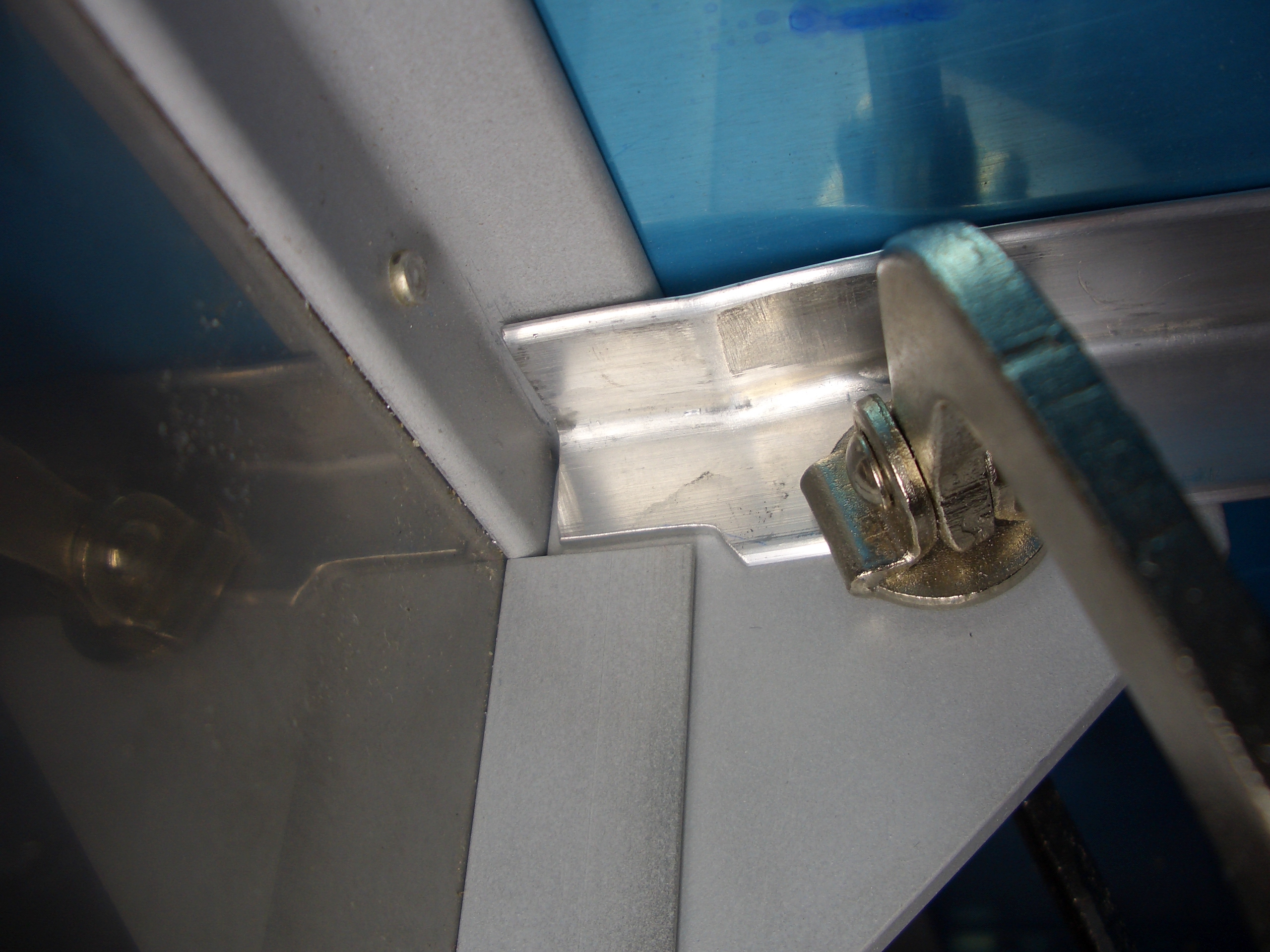
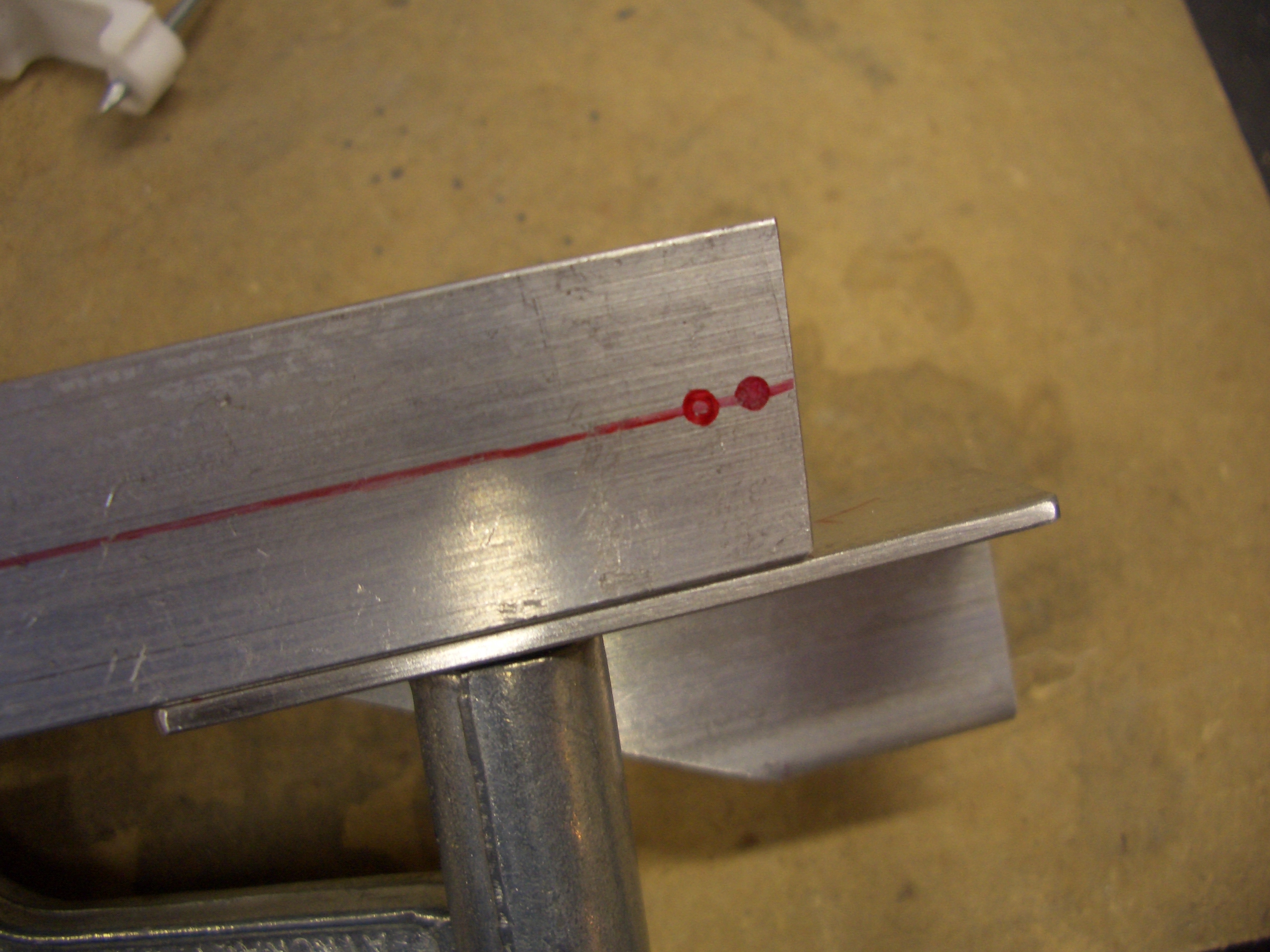
Finally, I marked the edges of the angle clip and drilled a hole in the center of the area.

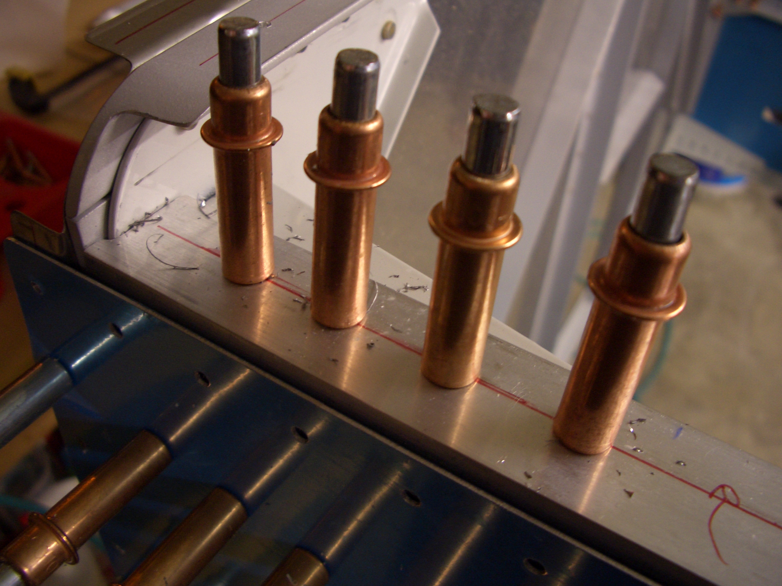
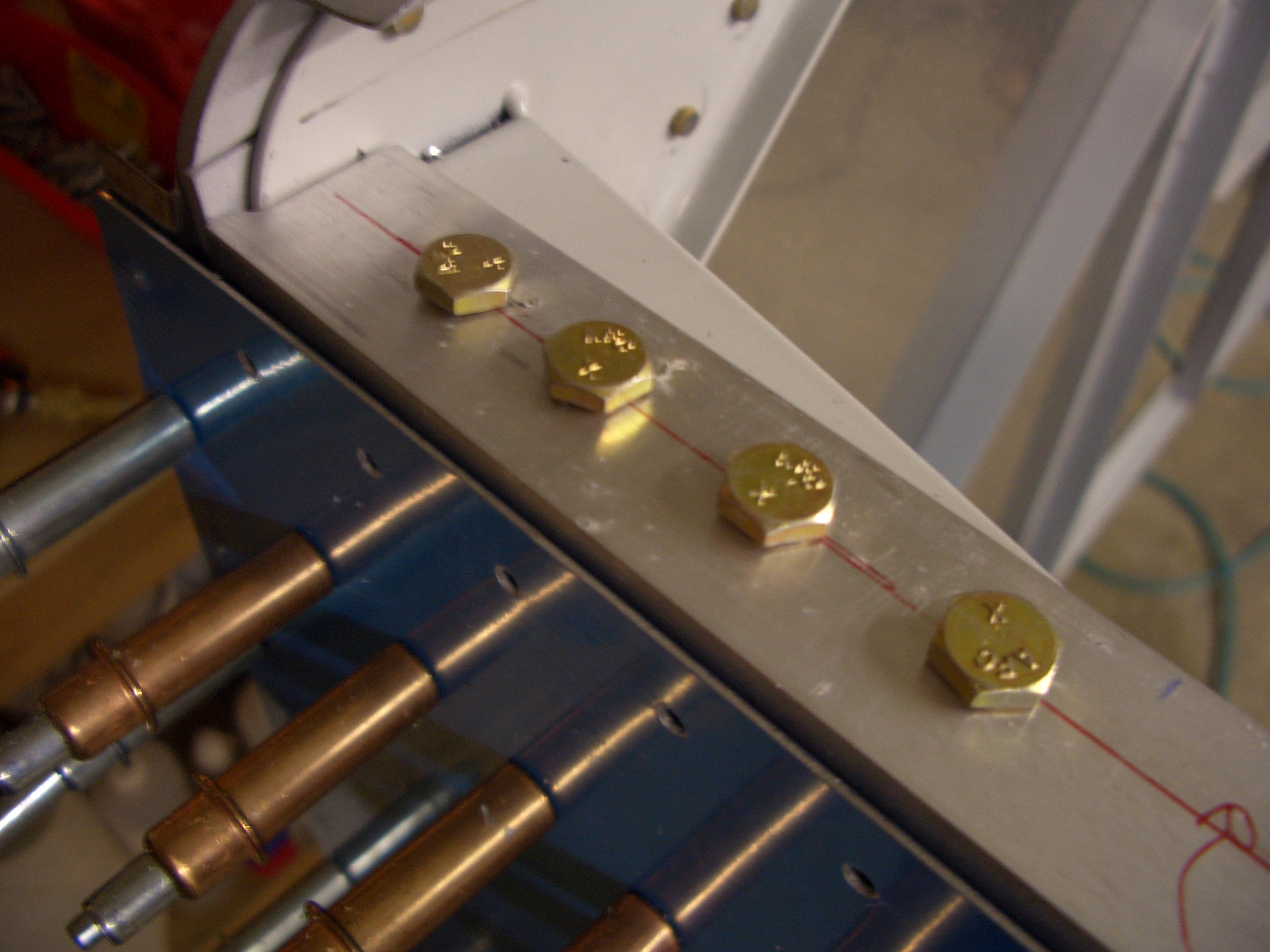
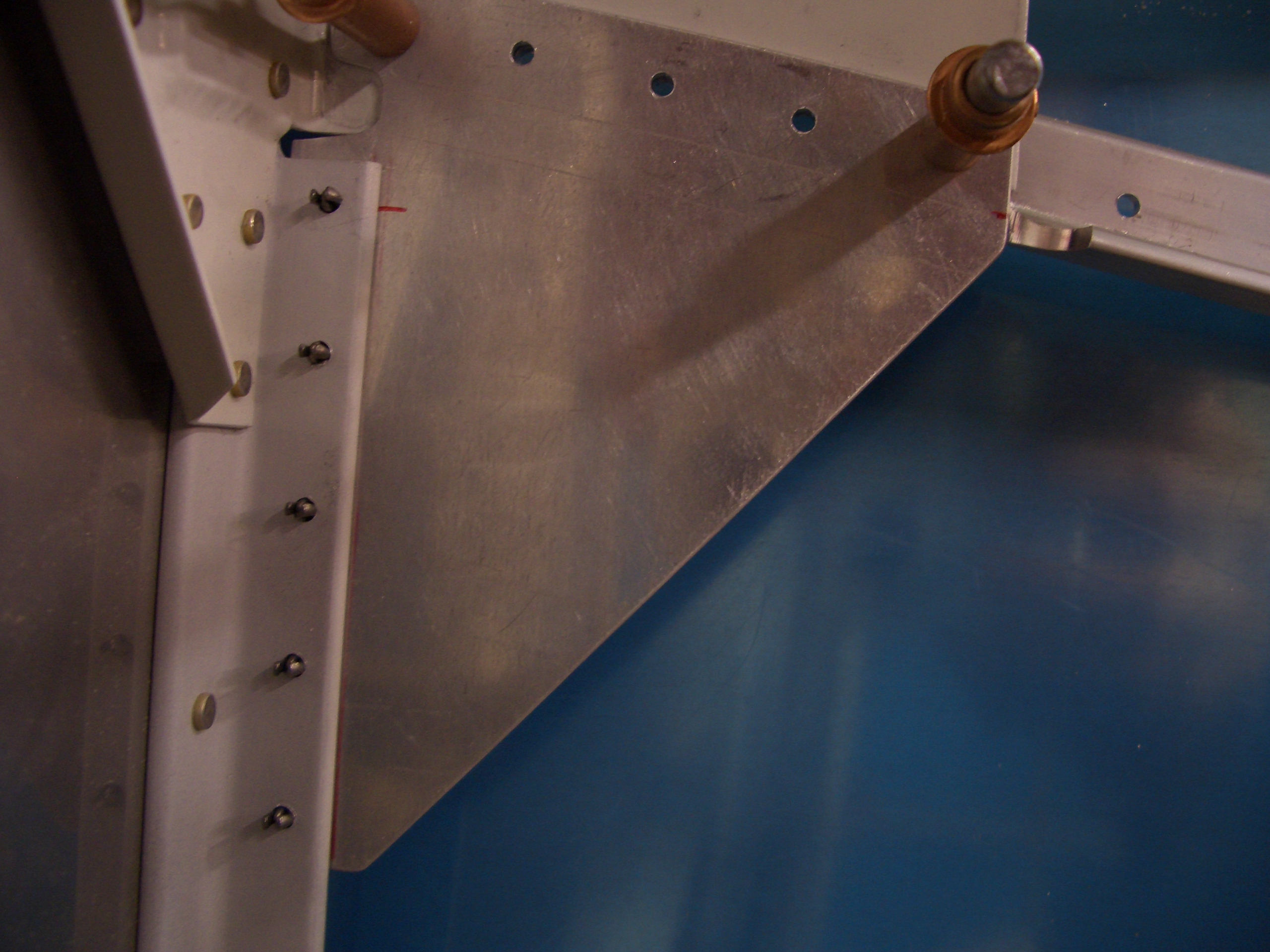
Edge distances came out great all around.

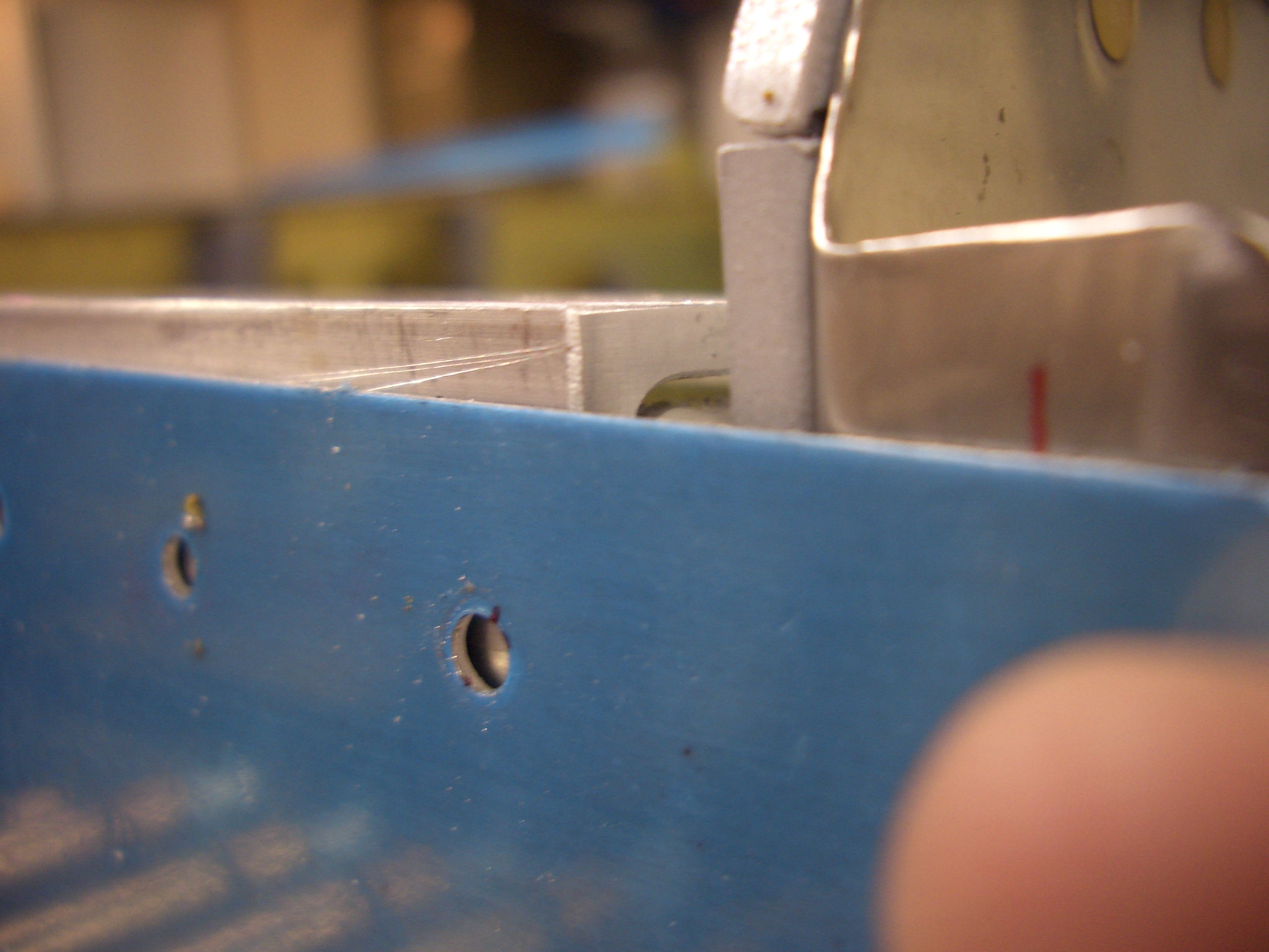
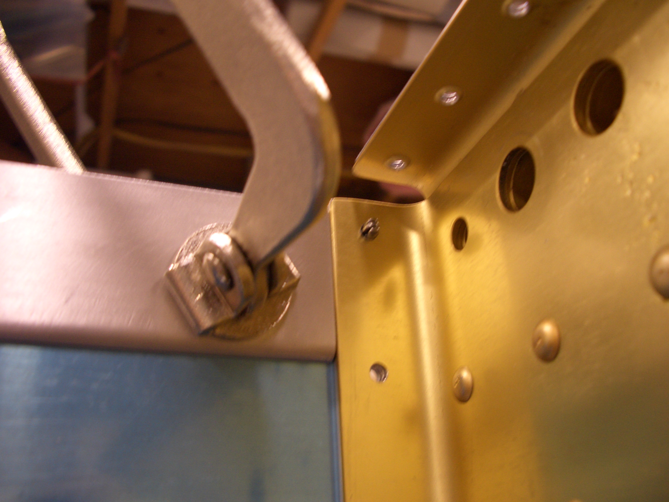
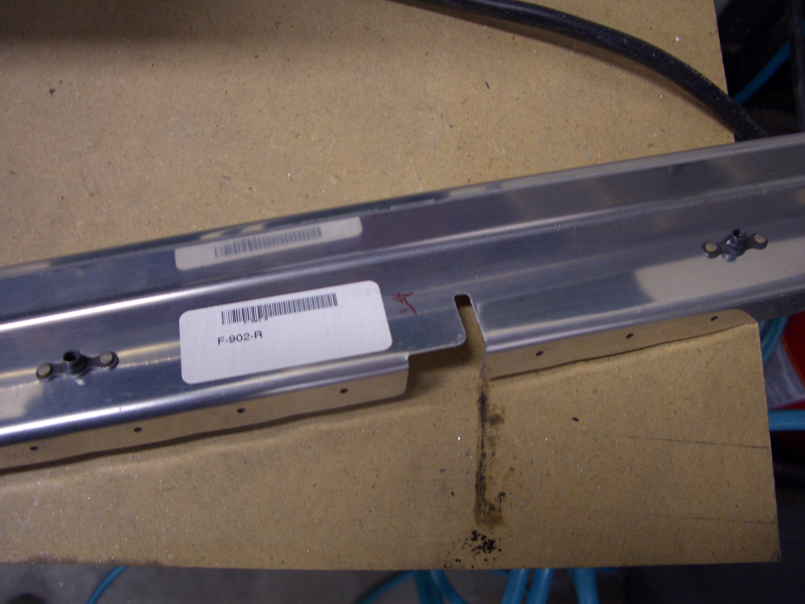
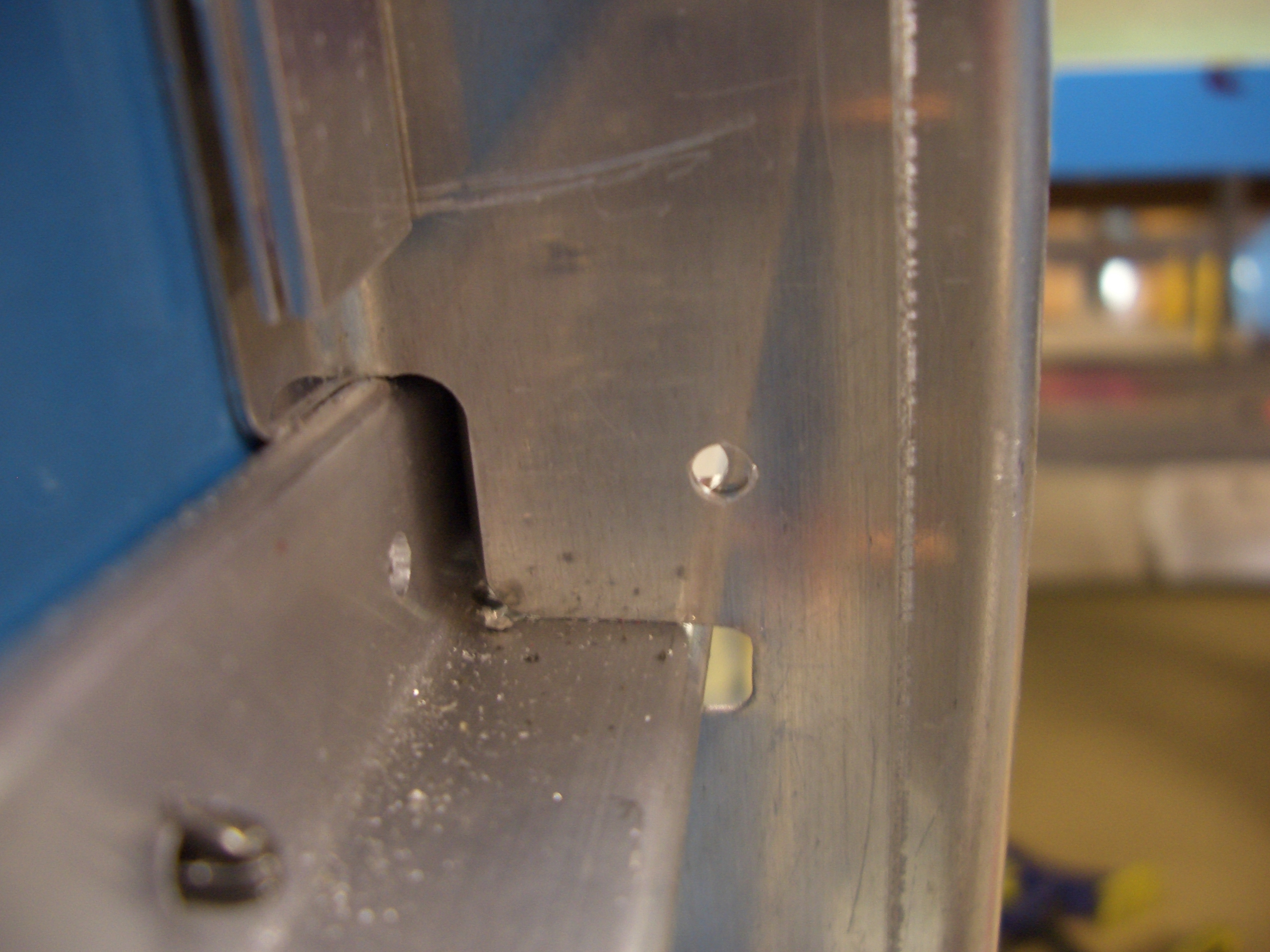
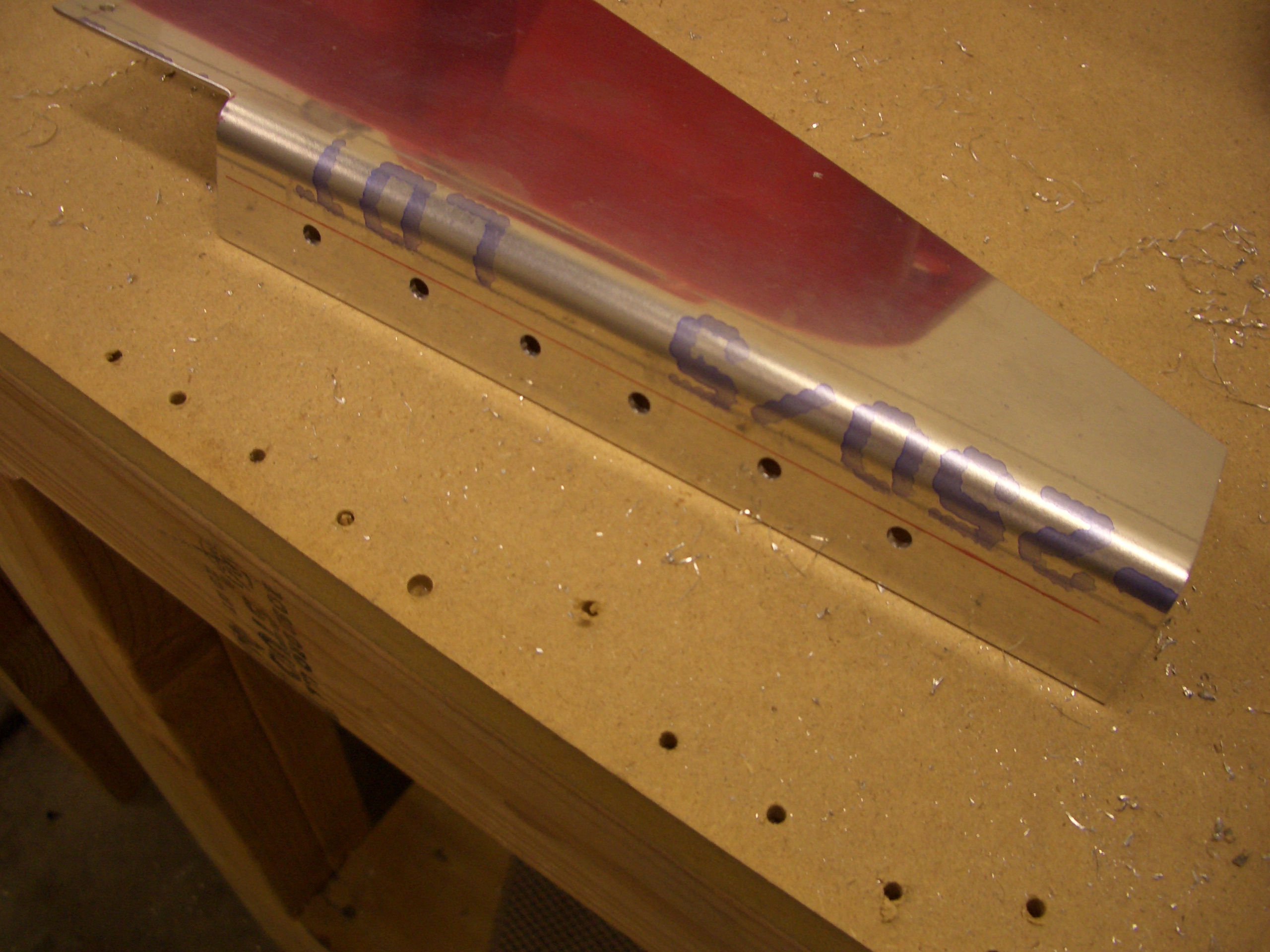
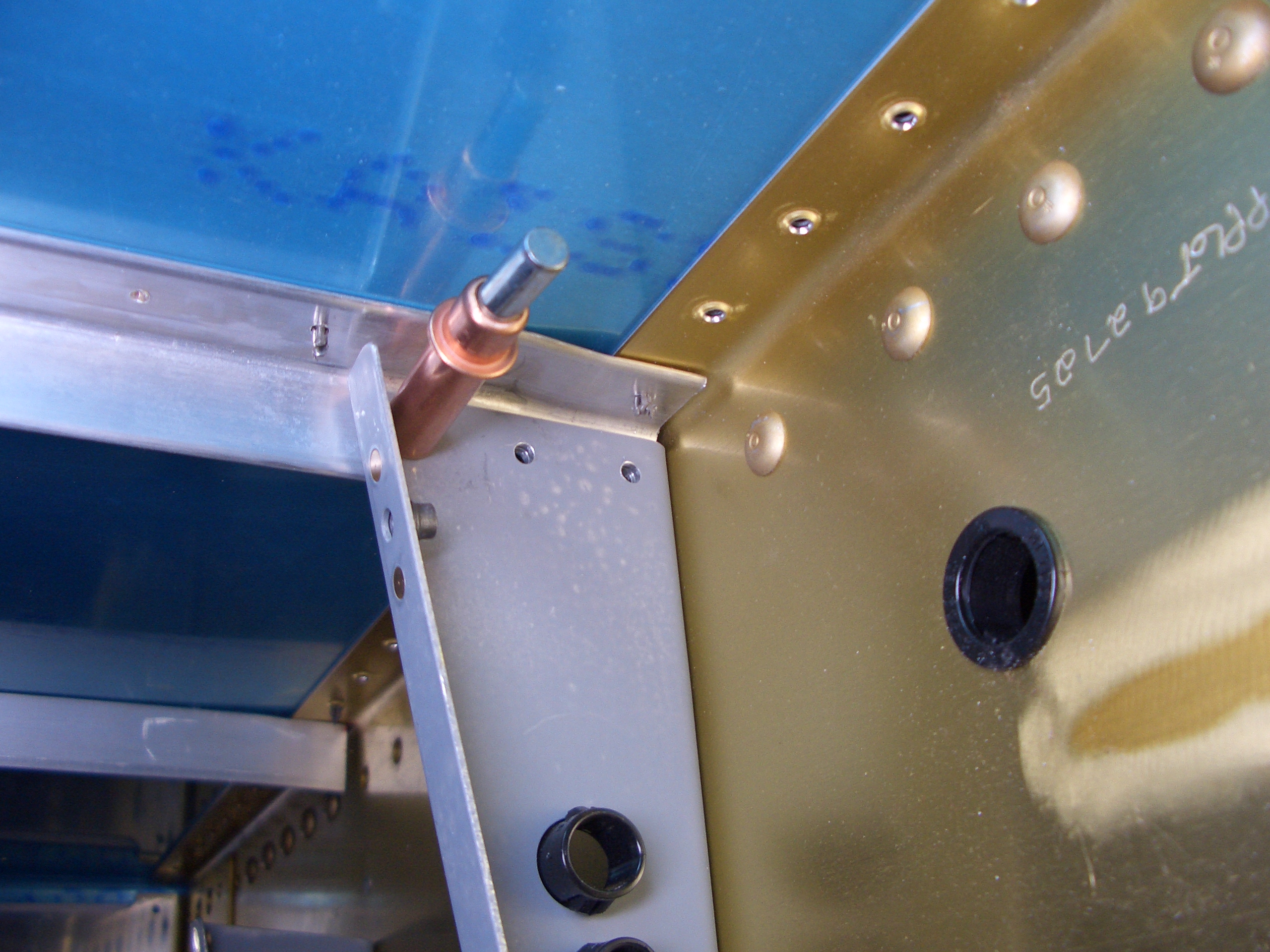
Here is the aft end showing how the stiffener steps up onto F-704.  Notice also that the hole to the left is on the flat of the stiffener.  I’ve noticed other builders having problems with the apex of the bend being forward of this hole which creates a gap between the skin and the stiffener at this hole.  If you trim the aft end of the stiffener first to get this hole in the right spot and then trim the forward end to just touch the firewall stiffener, then you can avoid this.

Finished Drilling Skin Stiffeners, Started Lower Longerons

I got started tonight by drilling the right skin stiffener.  Just like most other tasks, the second time went much faster than the first.

Next, I got started fabricating the lower longerons.  These are cut from raw 1″x1.25″x0.125″ angle stock.  The short leg of the angle needs to be removed for the aft 4.125″ of the longeron to provide clearance for a gusset that will tie this to F-704.  I made the rough cuts on a bandsaw and then used various files and scotchbrite roloc disks to get this nice and smooth.

If you look closely, you can see a gap between the horizontal leg of the longeron and the engine mount.  I anticipated that because Mike Bullock ran into the same problem.  The issue is that the lower longer and aux longeron meet at this bracket at an angle and the forward ends interfere.

A few seconds on the sanding wheel removed enough material that the lower longeron can nestle tightly into the bracket.

The longeron also needed to slide forward a bit to allow the rear end to fit next to F-704.  I could have just cut this off flush, but this relief cut gives me more edge distance on the frontmost bolt on the top and rivet on the side.

Here you can see how the aft end sits flush against the forward edge of F-704.

Before drilling any holes, I wanted to see what kind of edge distance I would have on the AN3 bolts that tie the longerons to the engine bracket.  The bolts are supposed to be centered in the longeron (1/2″ from the left edge where my finger is).  This gives me about 5/16″ edge distance for the bolt.  I know other builders have run into issues with edge distance here, so I want to make sure this is sufficient.

Update: I spoke with Ken at Van’s the next morning and he confirmed that 10/32″ was fine.

Finished Lower Longerons

I fit the lower right longeron.  Here is the forward end showing how it tucks around the lower engine mount.  I also drilled the bottom holes out to #30 to see what kind of edge distance I’d end up with on the mount.  You can sort of tell here that I biased the holes 1/16″ inboard of the center point on the longerons to give me slightly more edge distance on the steel.

Here you can see that I ended up with just over 12/32″ on the engine mount.  This is perfect as it means I more than 2d on both the mount and the longerons.

I first match drilled the mount to #30.

I then opened up each hole with a #15 bit (0.180″) before reaming it with a 3/16″ (0.1875) reamer.  I’m trying to only use reamers for all of the bolt holes.  They make perfectly circular holes that allow the bolts to slip in with virtually no play.  Here I’ve dropped some AN3 bolts in place to keep things aligned.  btw, it’s not an optical illusion, the bolts are intentionally spaced unevenly on the plans.

I repeated the procedure on the left side.  Edge distances came out great here as well with over 2d on all holes.

I laid out the F-684 gussets on the stock provided.  The area at the top and lower left that are marked with hatches need to be removed.

Two sides of the gusset need to be bent a few degrees to allow it to set flush on the engine mount and firewall stiffener.

After very careful checking to ensure sufficient edge distance, I drilled the left gusset to the lower engine mount.  I ended up with better than 2d on all holes but the one on the right which ended up at exactly 2d.

The skin can then be peeled back and the firewall stiffener can be match drilled using the holes I predrilled in the gusset.

All of these holes came out great as well with 2d or better all the way around,

I then repeated the process on the right side.  This came out nearly as well.  The upper left hole came out at slightly under 2d, but that’s still within spec.  This finishes up the forward longerons and skin stiffeners.

Fit Forward Bulkheads and Gear Attach Webs

The F-902 bulkheads need some tooling holes enlarged to 5/8″ for the rudder cables.  The aft flange also needs to be relieved so that it won’t interfere with the cable.  I also fluted the outside flange to bring the holes in line.

Nutplates are attached to the aft side of the bulkhead so that the fuel vent line can be attached with adel clamps.

Here is the right side clecoed in place.  Don’t bother at this point, I had to remove it to get the gear attach web in place.

I fit some 0.040″ thick scrap (the blue piece at the top) in place to correctly space the lower longeron away from the side skin.  I then clamped everything tightly together and drilled the gear attach web to the F-902 bulkhead.

Now that the bulkhead is positioned correctly, the bottom flange can be drilled to the lower longeron.

The upper flange can also be drilled to the upper longeron.

I then repeated the steps on the right side.

Assembled Brake Pedals

I started tonight by fabricating the shims that fit between the aux and lower longerons at F-902.  An angle will sit on top of these shims that will serve as the structural support for the forward tank attach bracket.

Unfortunately, when I took the clecos out of the gear web, the holes shifted.  It looks like I didn’t get the gear web fully seated in the aux longeron before match drilling it to the bulkhead.  This side is about 1/16″ off, the other side is about 1/32″ off.  I need to order some things from Van’s anyway, so I’ll go ahead and replace the bulkheads.

I skipped to the next section and began assembling the brake pedals.  I made the optional lightening cuts since every ounce counts.  Instead of the diagonal cuts at the bottom of the pedals, I cut a 1/2″ radius curve to match the radius of the lightening holes in the pedals.  The additional weight savings is negligible obviously, but I think it just looks better.

I drilled the UHMW rudder support blocks for the AN3 bolts that will be used to attach them to the skin stiffeners.  I’ve heard other builders complain about drilling this plastic, but if you turn your drill press down low and feed fairly aggressively (3-4 seconds to drill all the way through), the plastic comes out in one single shaving and the hole is perfectly clean.  You don’t even need to clamp the block (though make sure you hold it down firmly as you back the bit out).

I mounted the rudder tubes to the support blocks.  Make sure you pay attention to the orientation of the blocks.  The holes are not drilled perpendicular to the sides since the skin supports taper inward toward the firewall.

I clamped the rudder bars together with a piece of scrap angle and clamped the brake pedals together using a thick steel rule.  These are not the stock master cylinders that Van’s supplies (which are made by Matco).  These are made by Grove.  They are higher quality than the Matco units and are adjustable.

Drilled Brake Pedals and Mounted Rudder Pedals

I drilled the mounting holes and cut the center rudder support block in half.

Next, I mounted an AN3 bolt in the drill press and filed a point in the tip so that I could mark for the hole in the brake pedals.

The bolt slips through the bottom flange of the master cylinder and is used to scratch a mark in the side bar of the brake pedal.

Then it is a simple matter of finding the center of the hole and drilling for an AN3 bolt.

Then a few washers are used to space the master cylinders away from the brake pedal side bars.  I’m not mounting these permanently now, but I slipped the bolts in to make sure everything moves smoothly with no binding.

Next, I marked for three mounting positions for the rudder pedals.  The plans specify that the support blocks be no closer than 3″ aft of the firewall.  Since I’m tall (6′ 4″), I wanted the option of having the rudder pedals as far forward as possible.  I put marks at 3″, 4 1/16″, and 5 1/8″ which is the dimensions that Dan Checkoway came up with and many have copied.

Here are the holes drilled in the left skin stiffener.  I then repeated the process of the right side.

I then mounted the rudder pedals in the plane in preparation for drilling the center support.  It’s late, so this is a good place to stop.

Fabricated Rudder Pedal Brace

The center rudder pedal brace comes as a roughly shaped piece of thick alclad sheet with a bend along one side.  First a notch needs to be cut out of this flange of the sheet to clear the firewall recess.

I clecoed the firewall recess in place to make sure there is sufficient clearance between it and the rudder pedal brace.

Next, five holes are laid out along the edge that will rivet to the firewall stiffener.

After clamping everything in place and drilling the brace to the firewall stiffener, I put the center bearing block around the rudder tubes and drilled the brace for all three rudder positions.

Now that I’ve determined the aft most position for the pedals, I marked for removing the excess material to lighten the part.  Basically, I left an extra 5/8″ beyond the aft hole and marked a vertical line (the area on the right) and then came up 1″ from the bottom flange and marked a tapering cut from the top left apex to that mark.

After removing the excess material marked above, I cut a series of lightening holes.  The dimension I used were 2 1/4″ for the large hole, 1 1/4″ for the medium hole, and 3/4″ for the small hole.

With that, the rudder and brake pedals are done and can be removed from the plane for the time being.  I’m not going to rivet the brake pedals together now because I’m going to have them anodized along with a couple of other components, and I don’t want to have to pay multiple shop fees for the anodizing.

More Deburring

I haven’t had much time this week due to various projects around the house, but I managed to get a little more work done on the plane tonight.  I deburred a few more of the stiffeners and bulkheads and dimpled the tailcone.  I should be able to spend a fair amount of time this weekend on the project.

Drilled Center Floor Stiffeners

I clecoed the bottom forward skin back on and pulled out the floor stiffeners.  Just like the side skin stiffeners, I had to use my hand squeezer and a couple of scrap pieces of angle to get these to sit flat on both the skin and the angle.  The forward ends of the two center stiffeners also needed small relief cuts to clear one of the firewall stiffeners.

After confirming sufficient edge distance on the skin holes, I match drilled the stiffeners to the skins.

Here is a shot of the inside.  The clamps holding these stiffeners to the beefy angle on the firewall and the cover support ribs on F-704 still need to be drilled.  That will tie all of these structures together quite firmly.

Finished Drilling Floor Stiffeners

I managed to drill the two outboard floor stiffeners by myself.  The problem with these is that there is nothing to clamp them to.  I ended up using some duct tape and a long stick to prop them up against the skin until I could get a hole at each end drilled.  After that it was pretty straightforward.

The two center stiffeners also needed to be drilled to the cover support ribs at the aft end.

And they need to be drilled to the F-601J angles on the front end.  DWG 19 specifies that these should be drilled in assembly with the floor stiffeners, but it would have been much easier if I had laid these out and at least drilled them out to #40 back when I was constructing the firewall.  Oh well, I managed to get it done without too much pain.