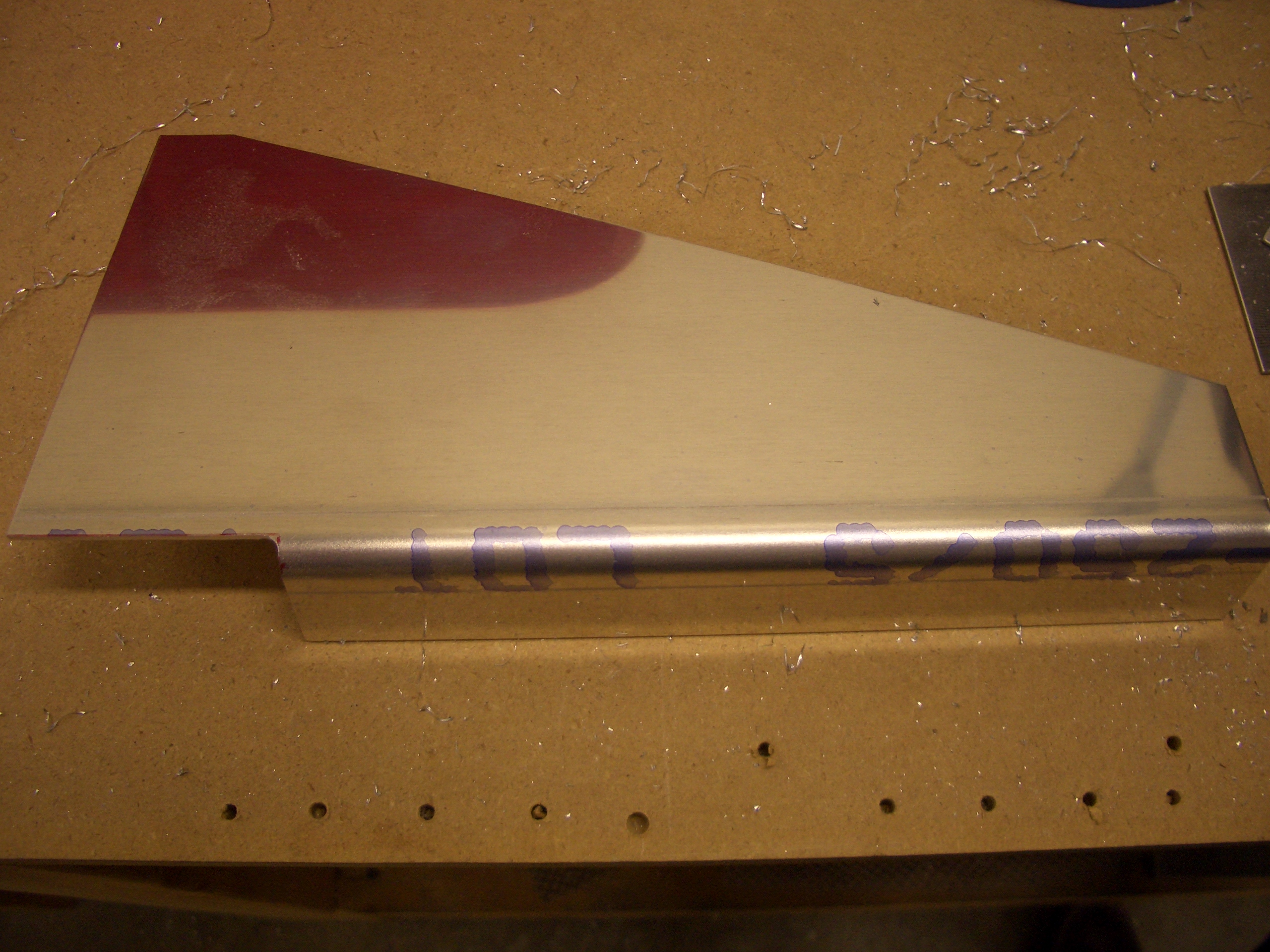
The center rudder pedal brace comes as a roughly shaped piece of thick alclad sheet with a bend along one side. First a notch needs to be cut out of this flange of the sheet to clear the firewall recess.
I clecoed the firewall recess in place to make sure there is sufficient clearance between it and the rudder pedal brace.

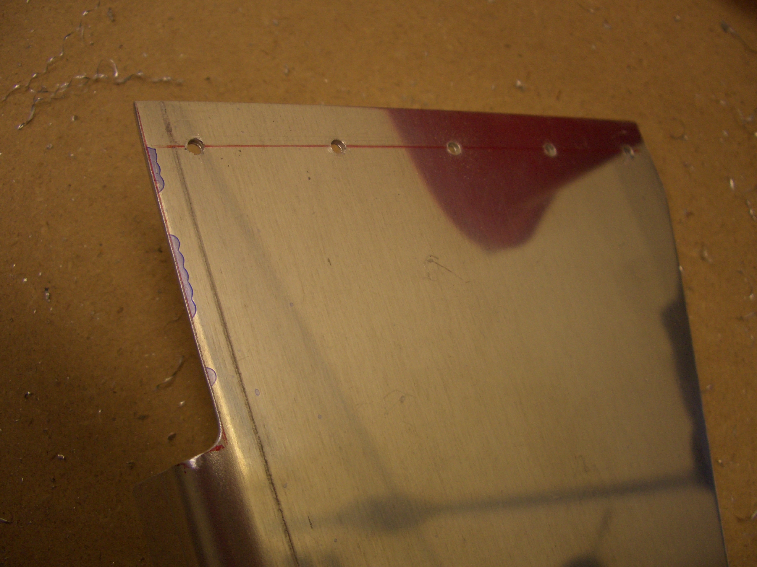
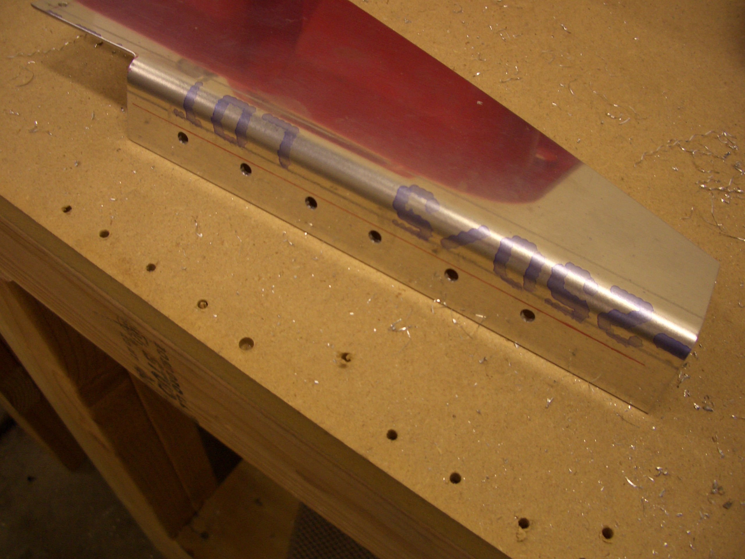
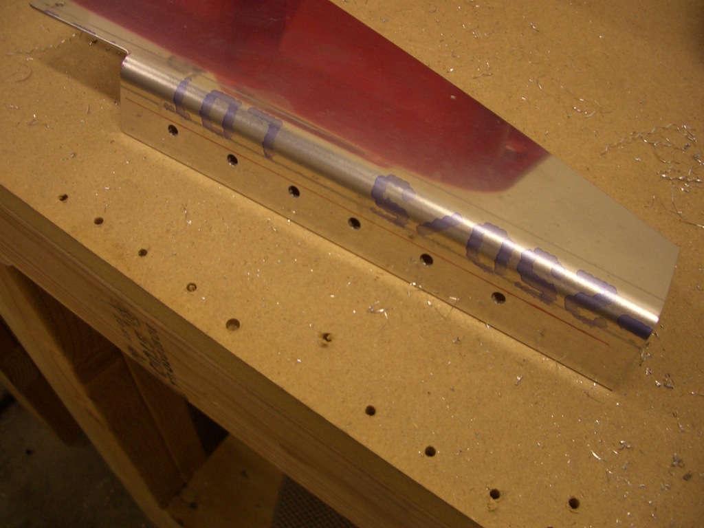
Next, five holes are laid out along the edge that will rivet to the firewall stiffener.

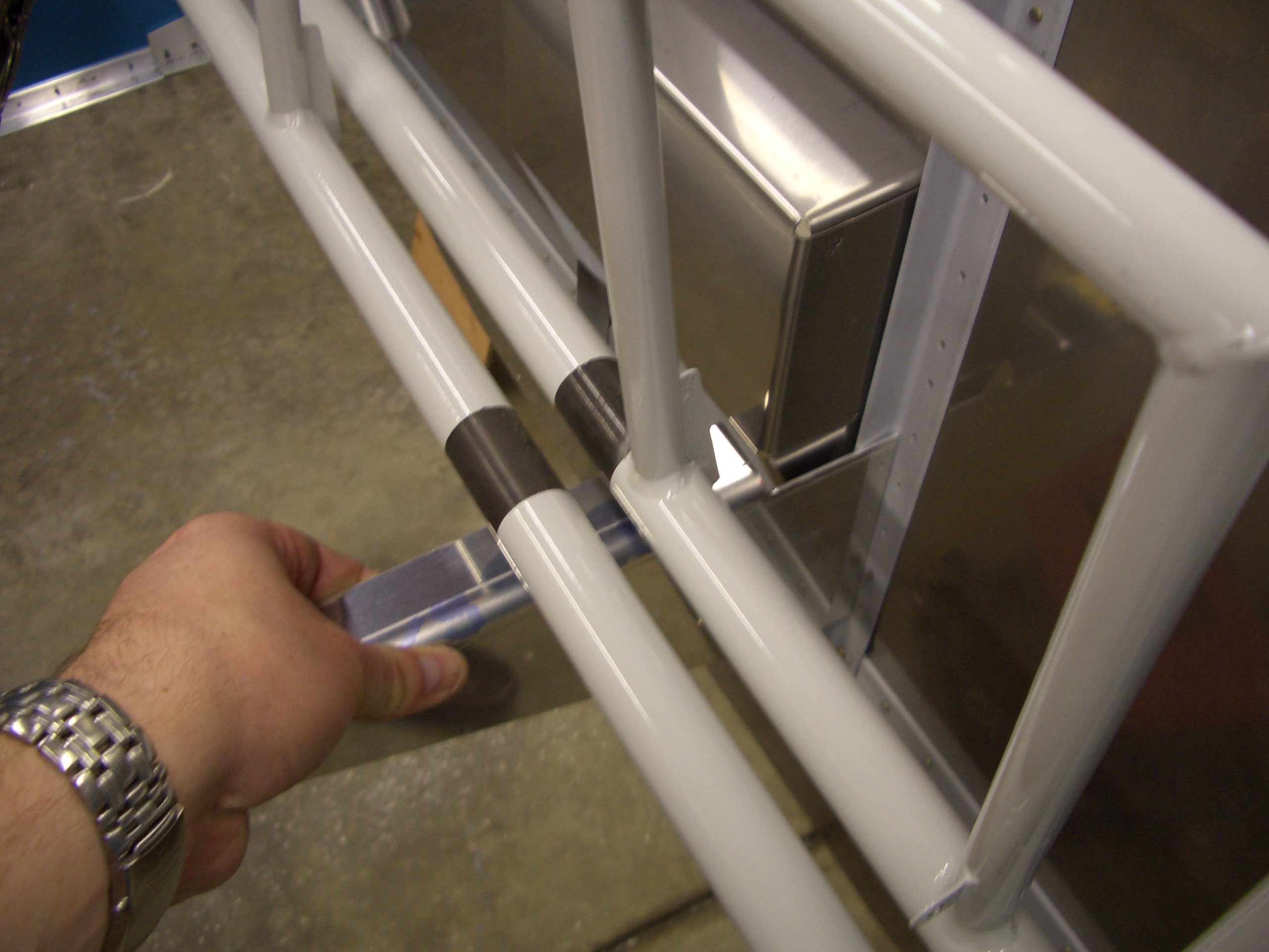
After clamping everything in place and drilling the brace to the firewall stiffener, I put the center bearing block around the rudder tubes and drilled the brace for all three rudder positions.
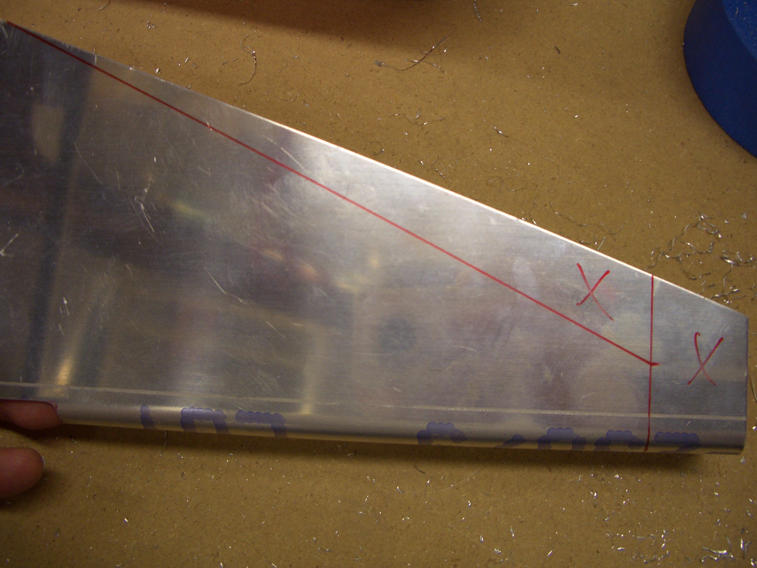
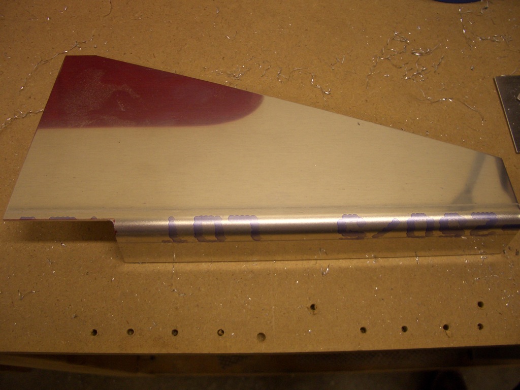
Now that I’ve determined the aft most position for the pedals, I marked for removing the excess material to lighten the part. Basically, I left an extra 5/8″ beyond the aft hole and marked a vertical line (the area on the right) and then came up 1″ from the bottom flange and marked a tapering cut from the top left apex to that mark.

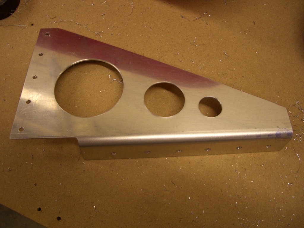
After removing the excess material marked above, I cut a series of lightening holes. The dimension I used were 2 1/4″ for the large hole, 1 1/4″ for the medium hole, and 3/4″ for the small hole.
With that, the rudder and brake pedals are done and can be removed from the plane for the time being. I’m not going to rivet the brake pedals together now because I’m going to have them anodized along with a couple of other components, and I don’t want to have to pay multiple shop fees for the anodizing.