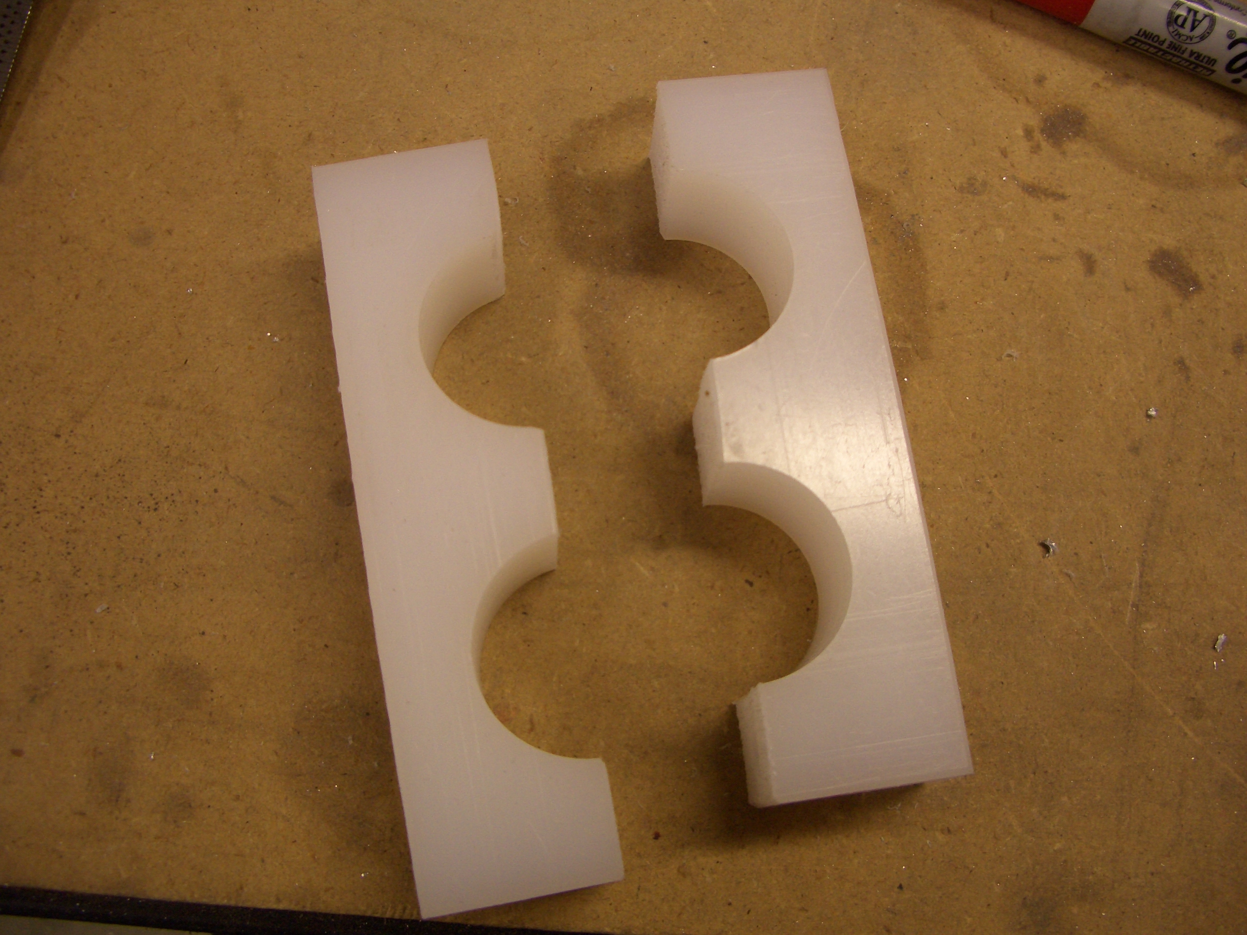
I drilled the mounting holes and cut the center rudder support block in half.
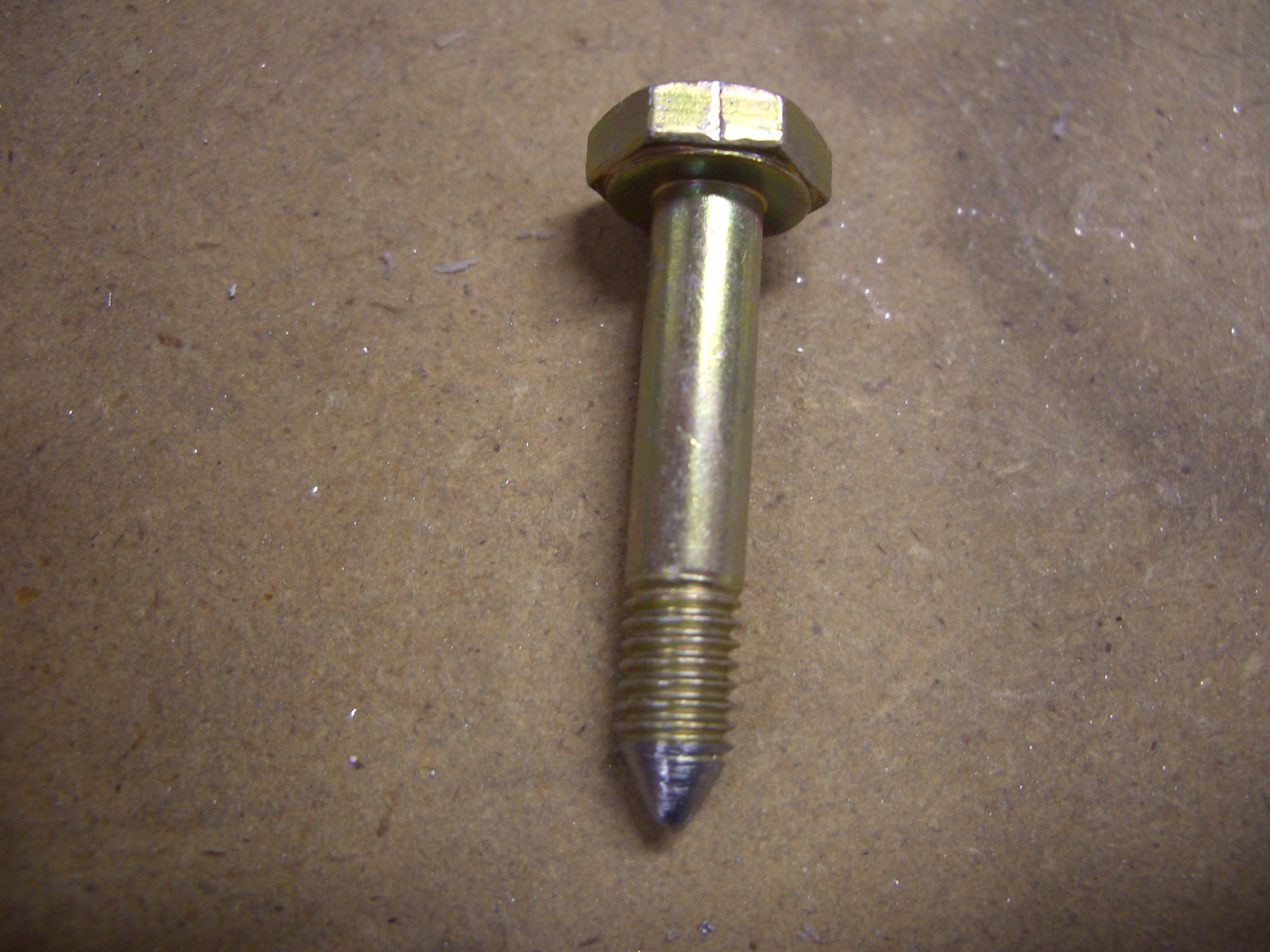
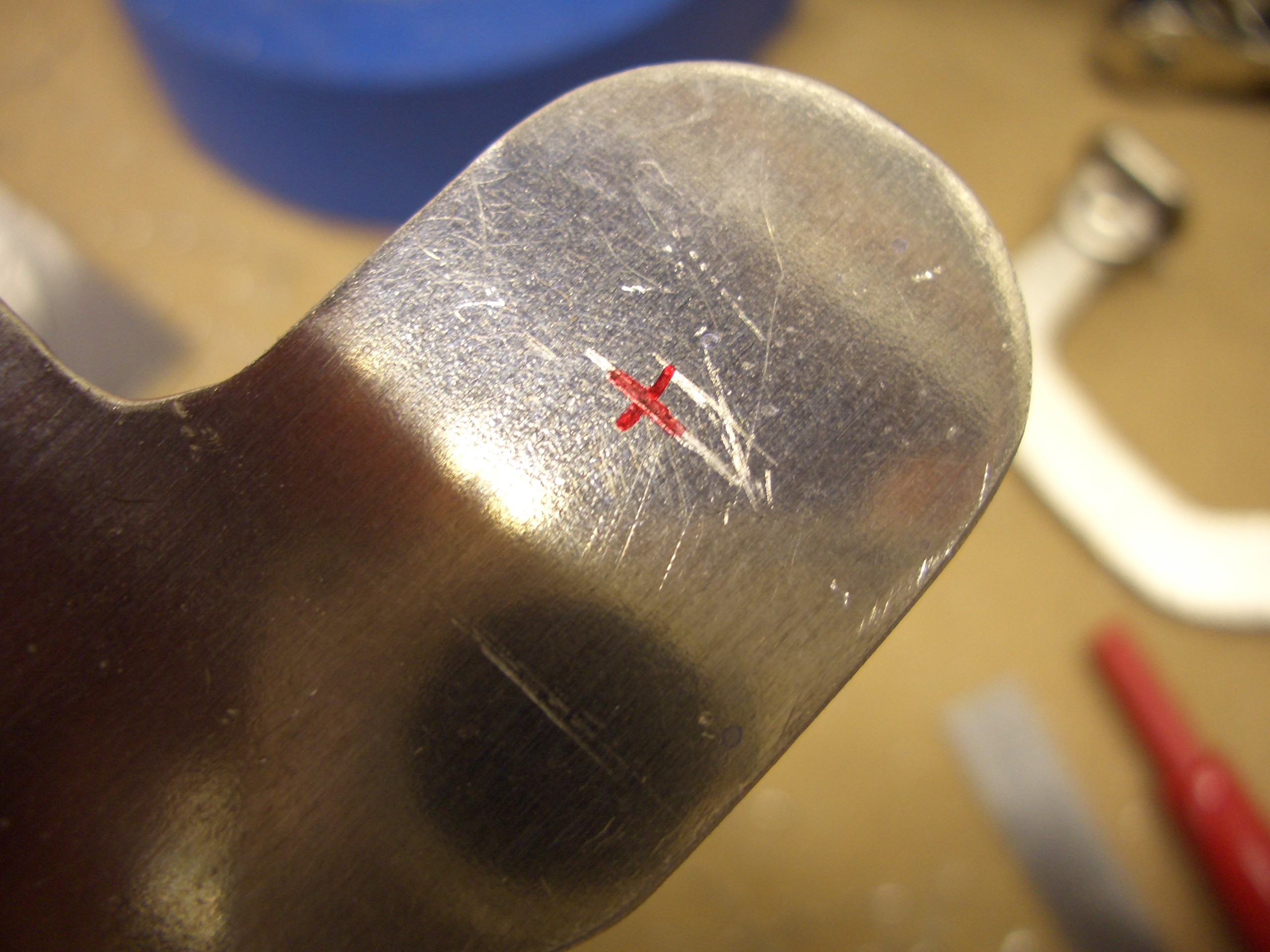
Next, I mounted an AN3 bolt in the drill press and filed a point in the tip so that I could mark for the hole in the brake pedals.
The bolt slips through the bottom flange of the master cylinder and is used to scratch a mark in the side bar of the brake pedal.
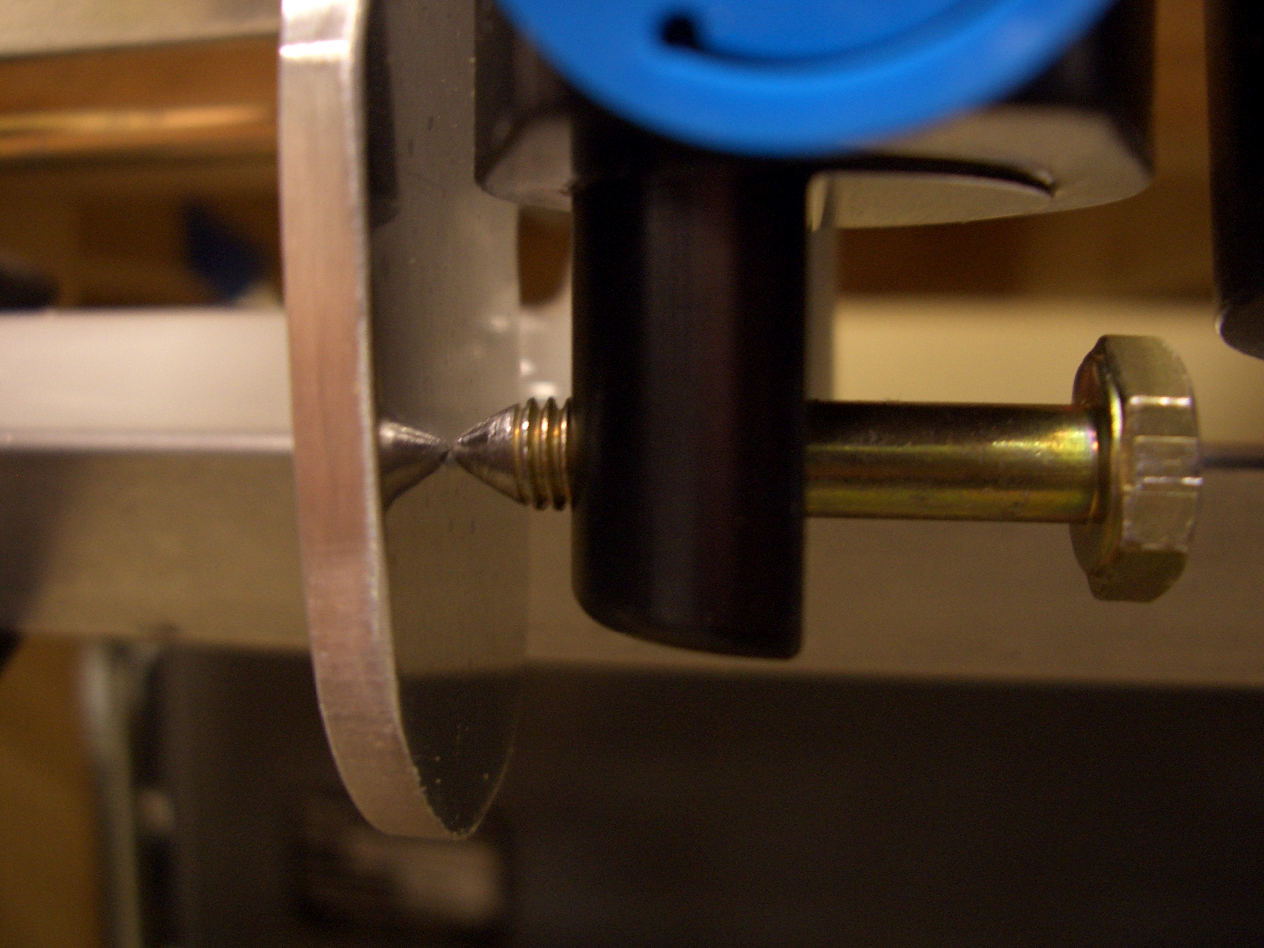
Then it is a simple matter of finding the center of the hole and drilling for an AN3 bolt.
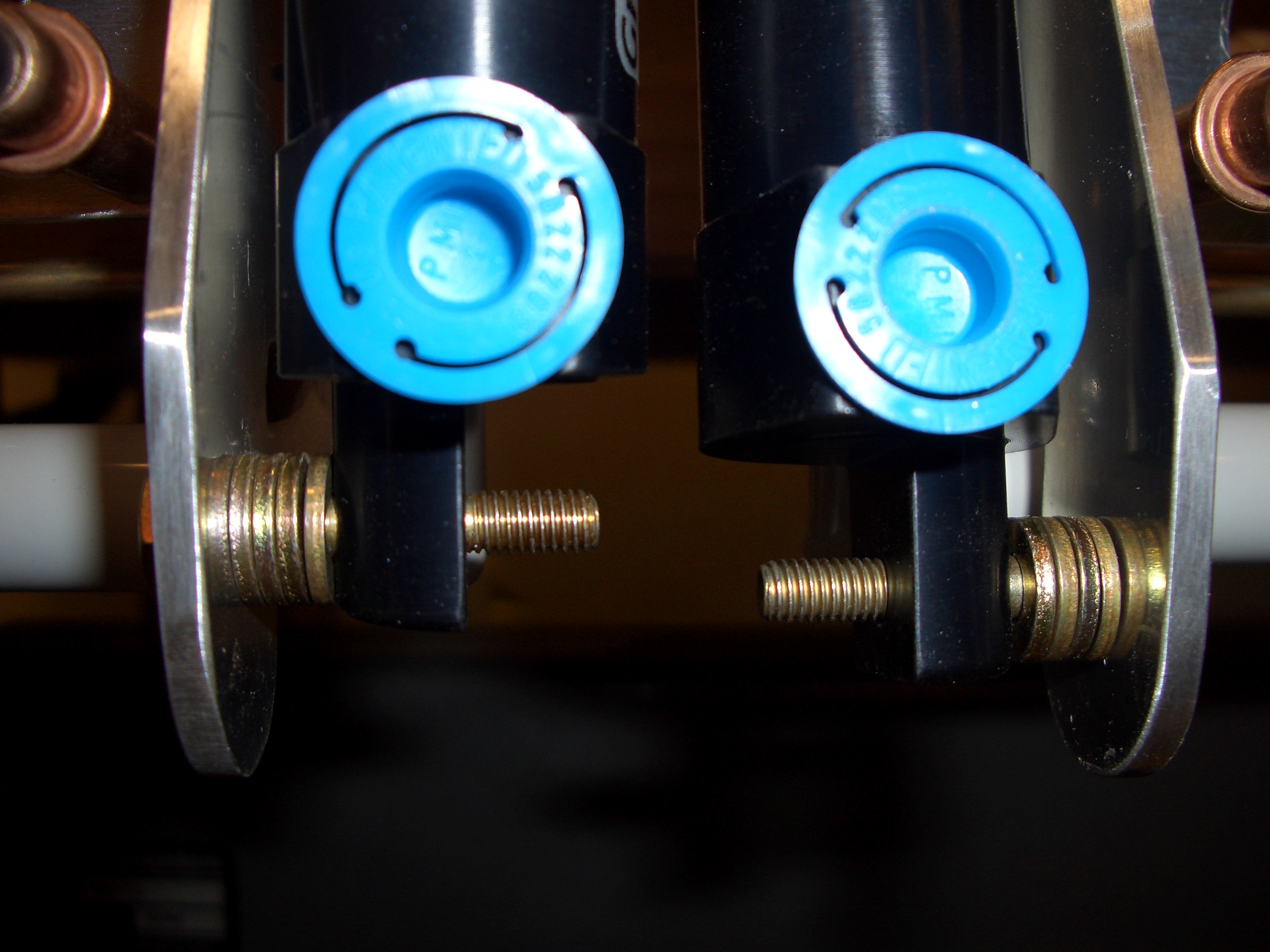
Then a few washers are used to space the master cylinders away from the brake pedal side bars. I’m not mounting these permanently now, but I slipped the bolts in to make sure everything moves smoothly with no binding.
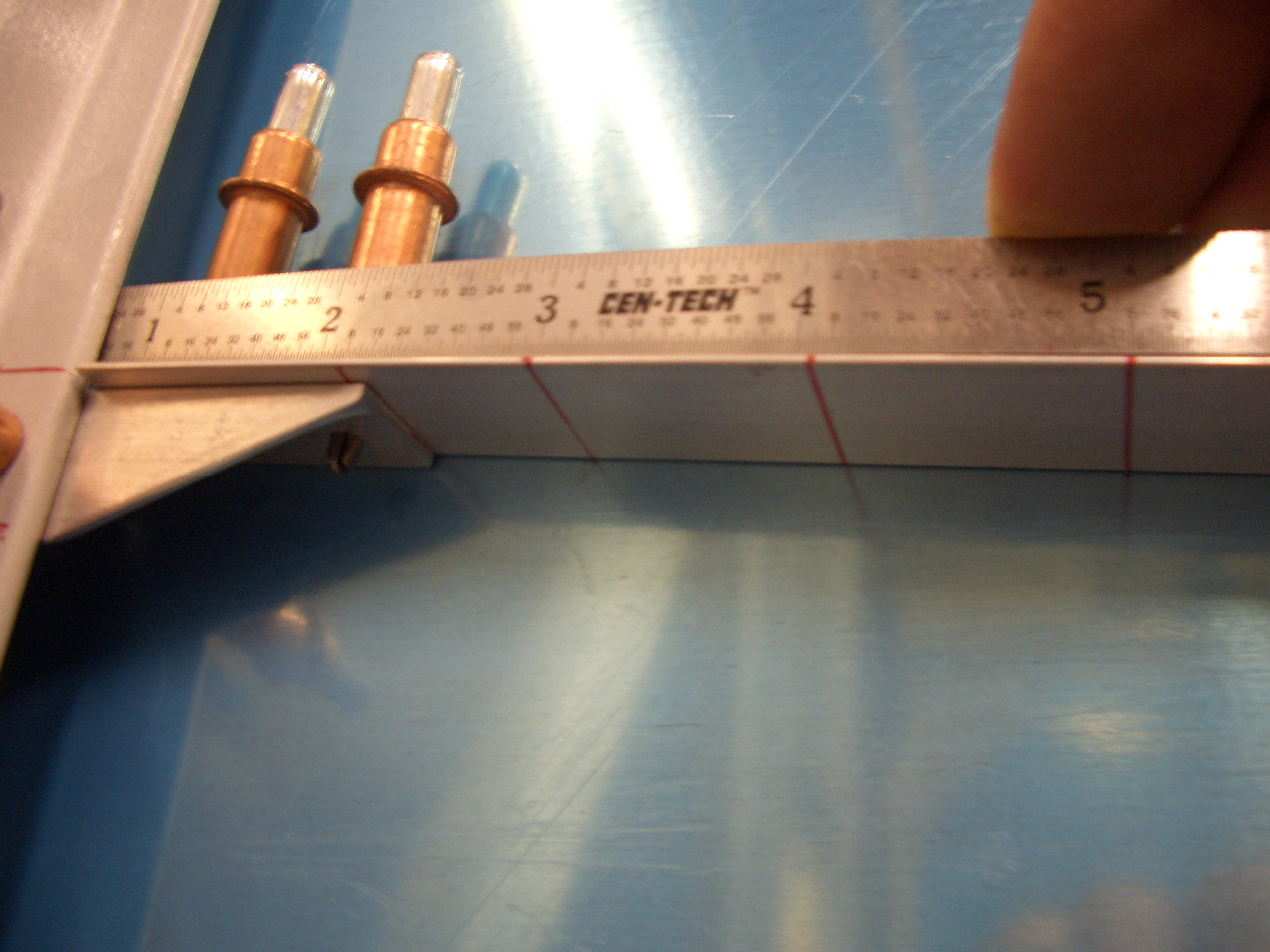
Next, I marked for three mounting positions for the rudder pedals. The plans specify that the support blocks be no closer than 3″ aft of the firewall. Since I’m tall (6′ 4″), I wanted the option of having the rudder pedals as far forward as possible. I put marks at 3″, 4 1/16″, and 5 1/8″ which is the dimensions that Dan Checkoway came up with and many have copied.
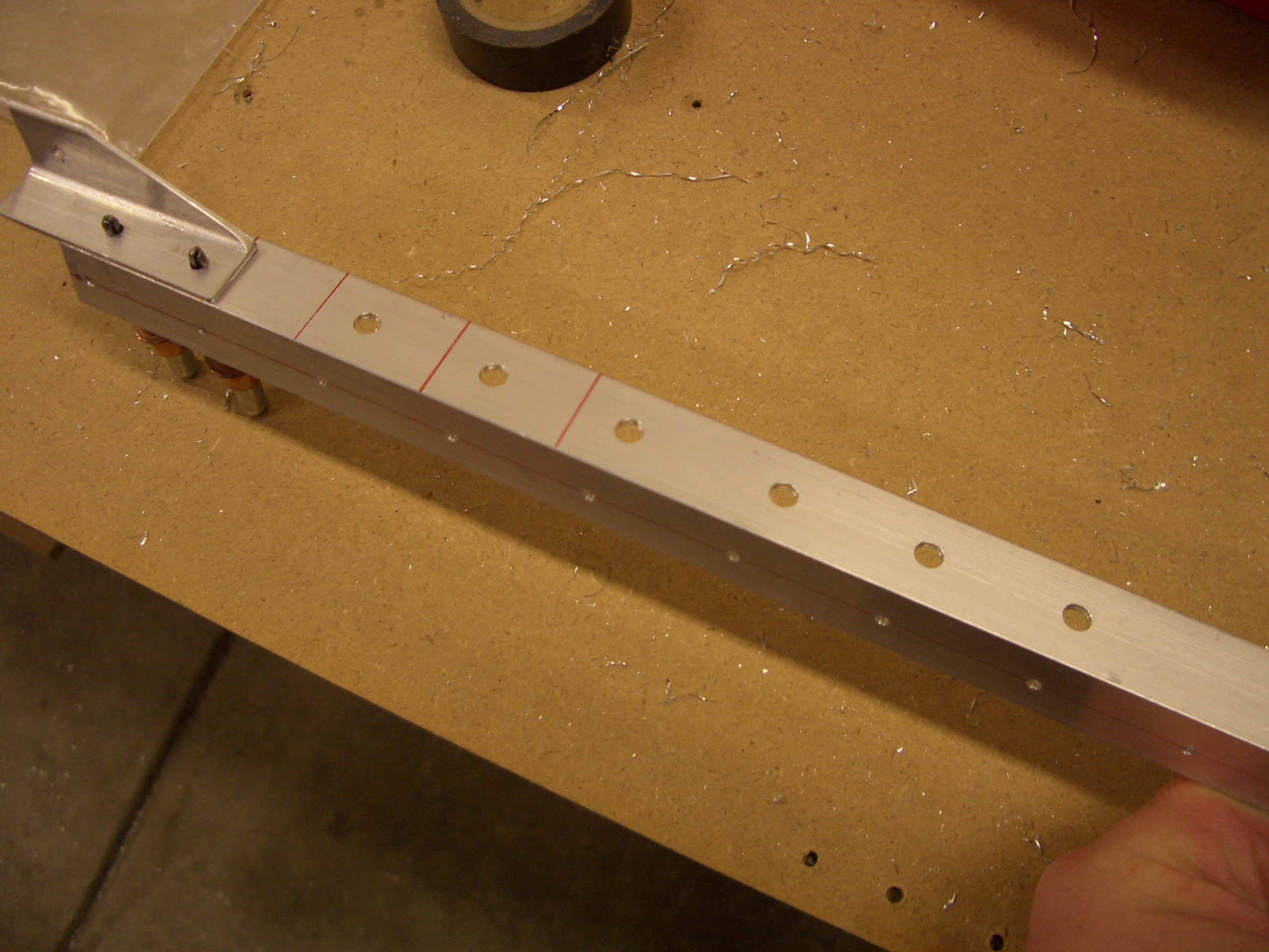
Here are the holes drilled in the left skin stiffener. I then repeated the process of the right side.
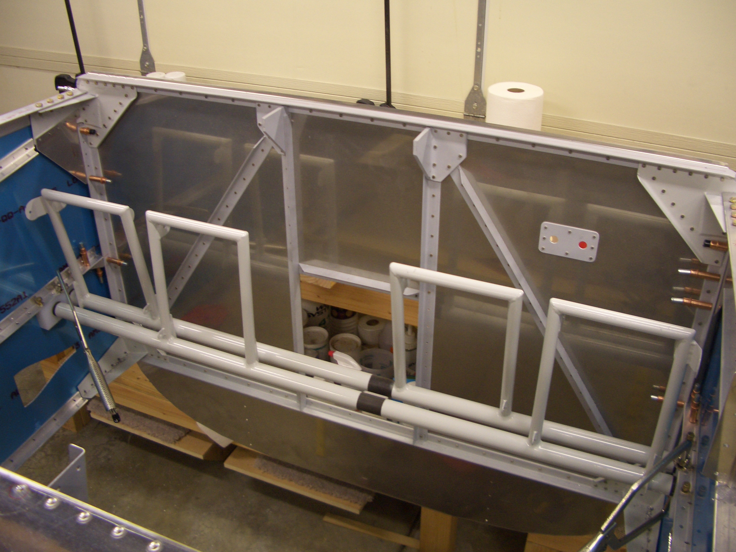
I then mounted the rudder pedals in the plane in preparation for drilling the center support. It’s late, so this is a good place to stop.