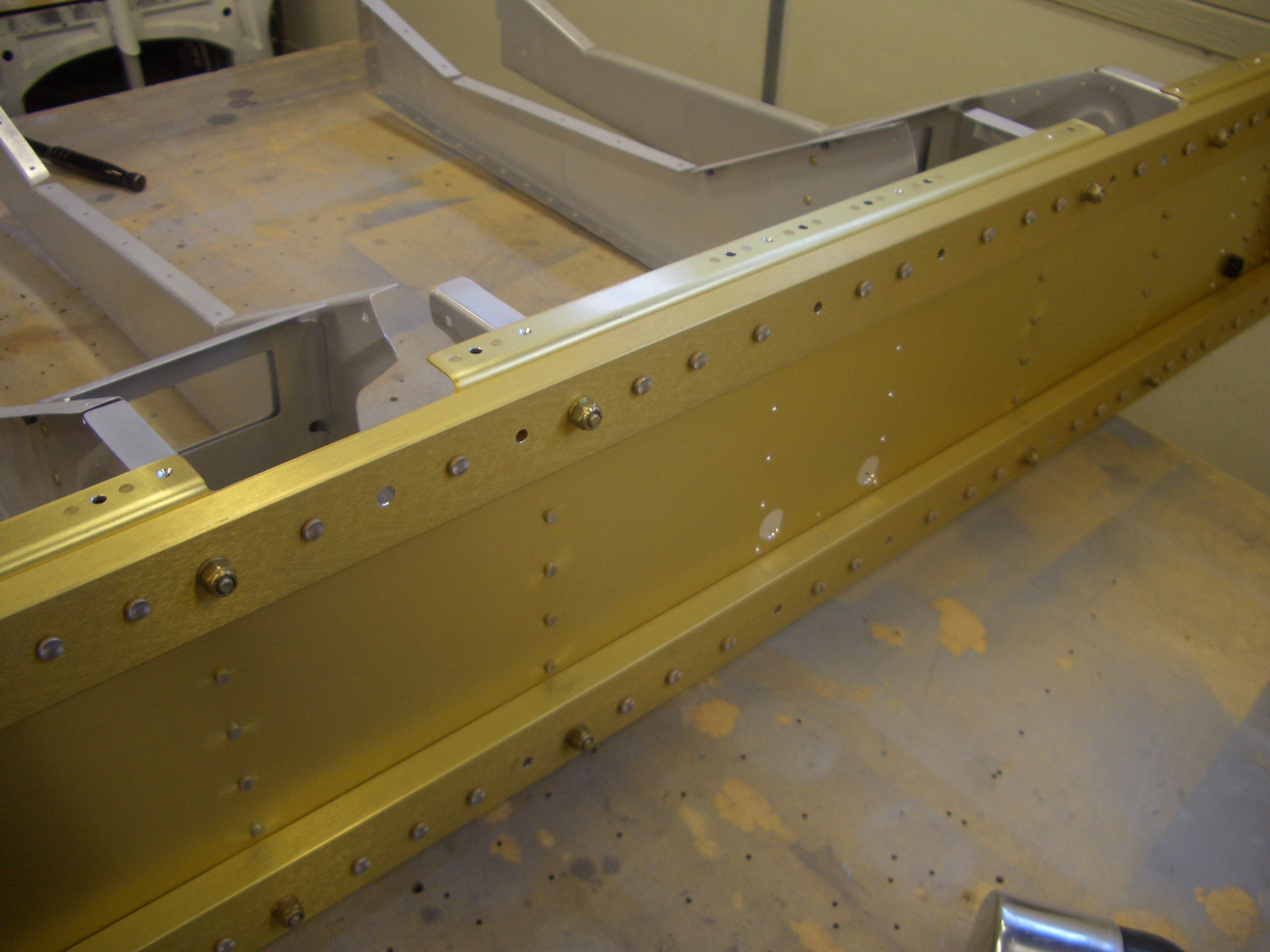
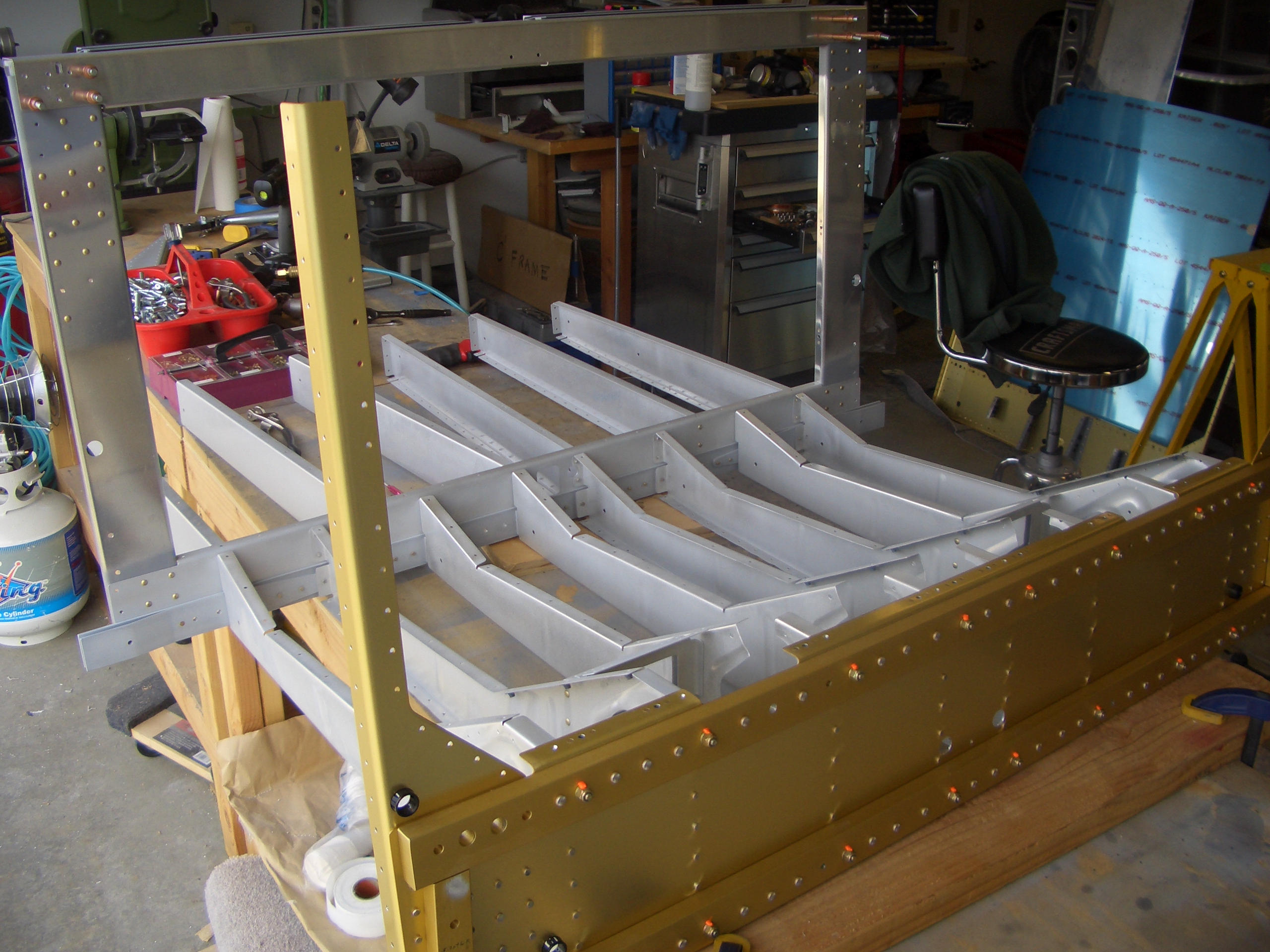
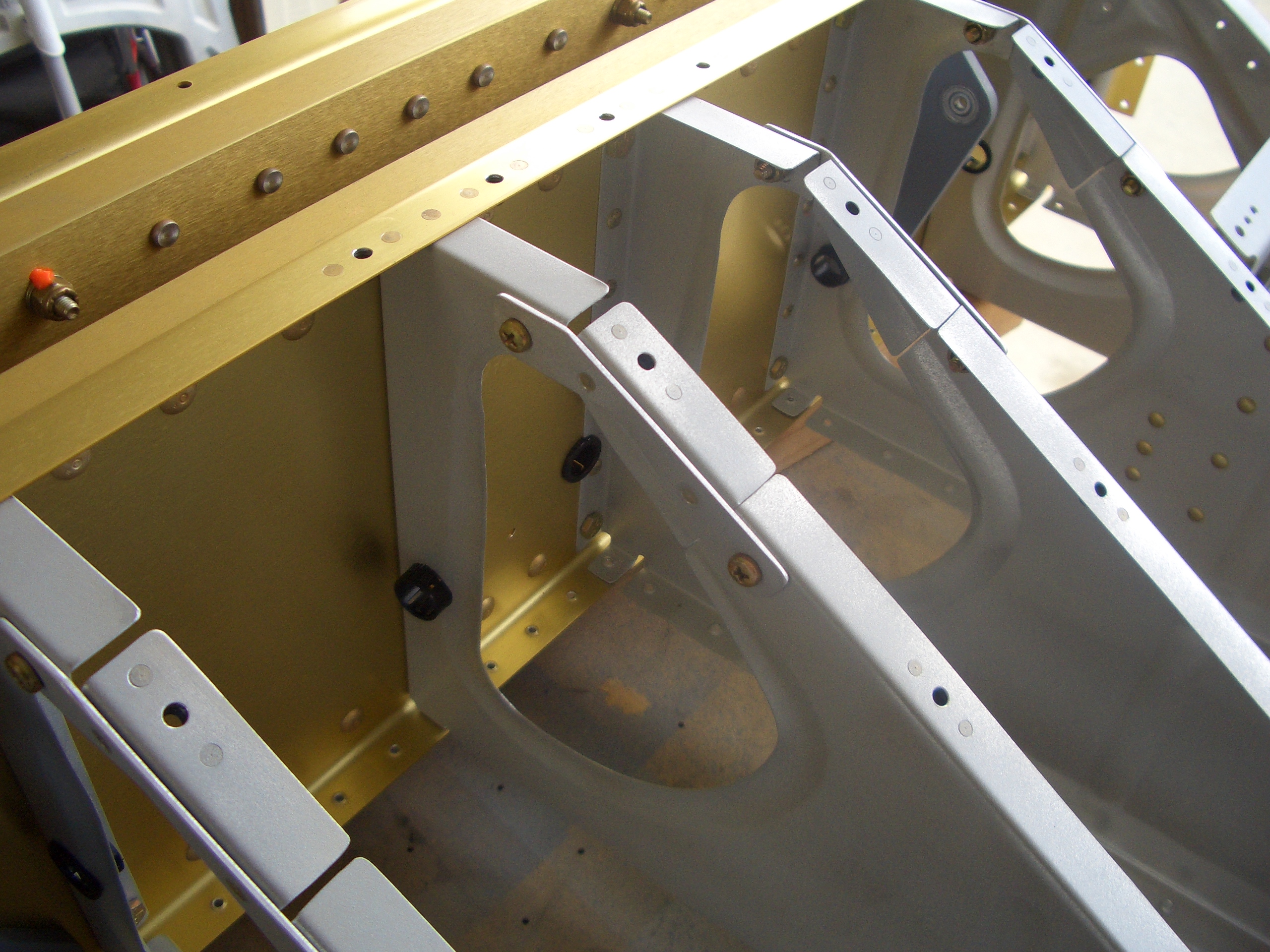
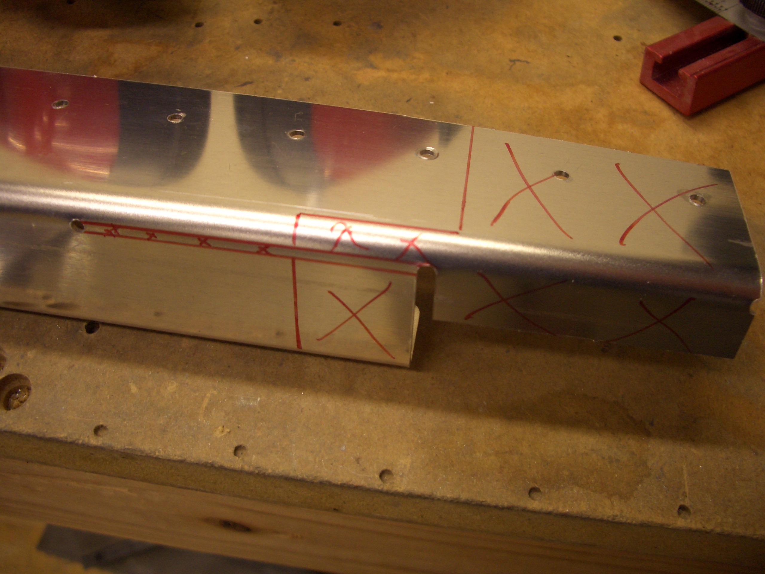
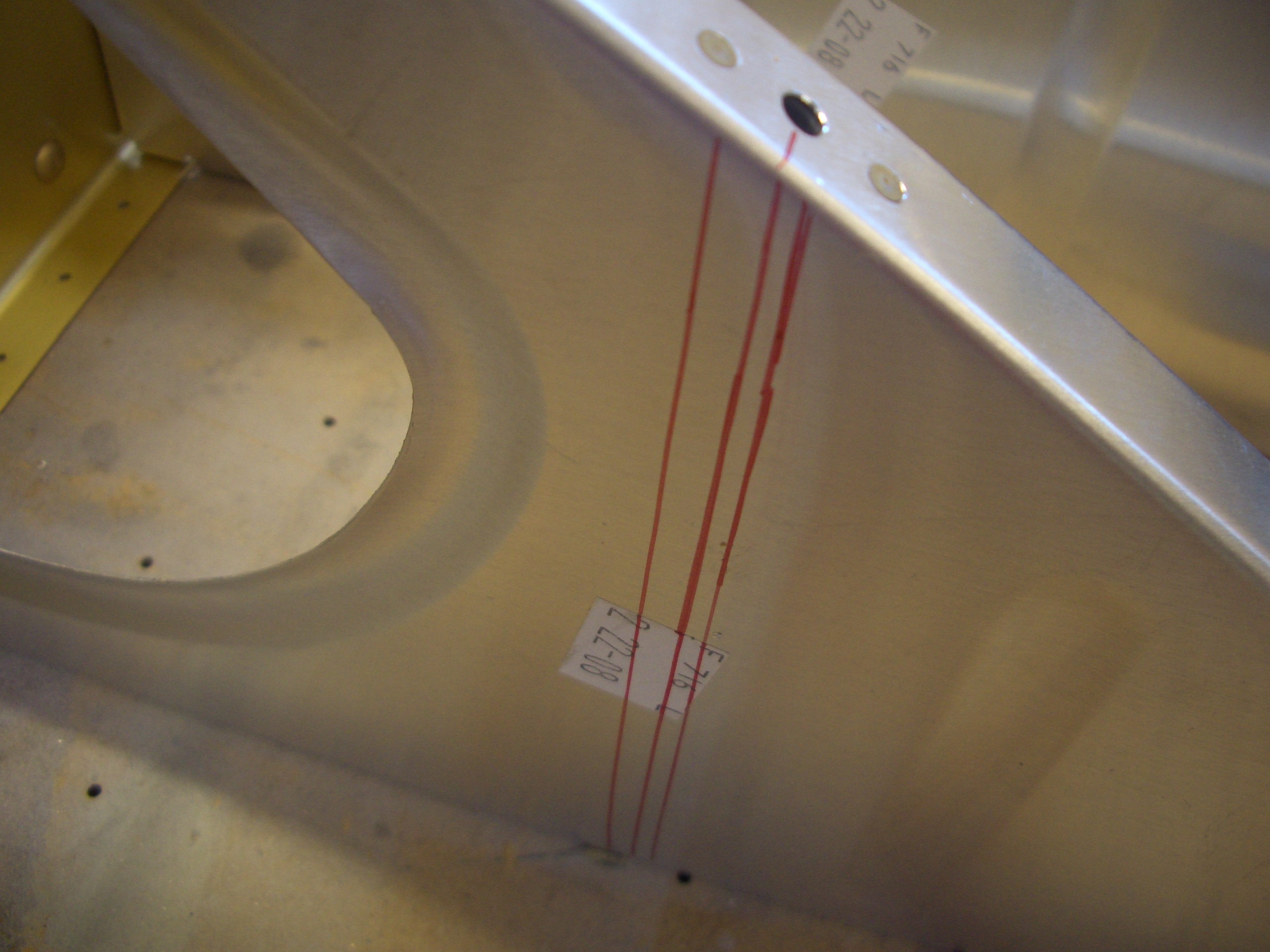
I started today by installing the crotch strap brackets. I’m either going with Hooker or Crow harnesses, but either way, the spacing between the brackets has to be increased to 5/16″ (instead of the stock 1/8″ spacing). Mike Bullock already determined the best way to accomplish this and documented it here, so I’m just going to copy his method (thanks Mike). I put a center line that is aligned with middle nutplate, then measured 7/32″ forward and 3/32″ aft of this line and put additional marks.
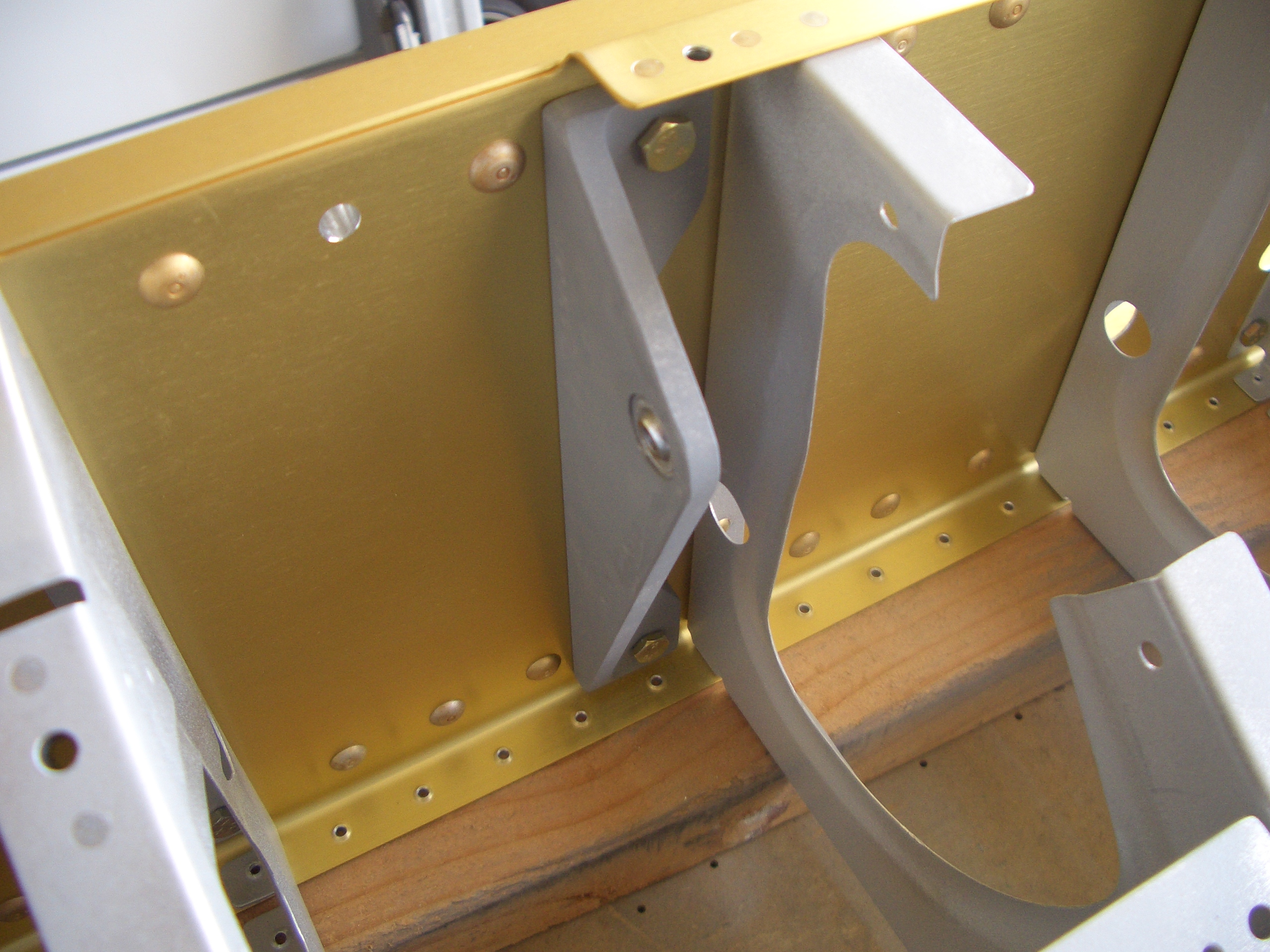
The front side of the bracket is positioned with the web flush with the forward line and drilled to the adjacent ribs.
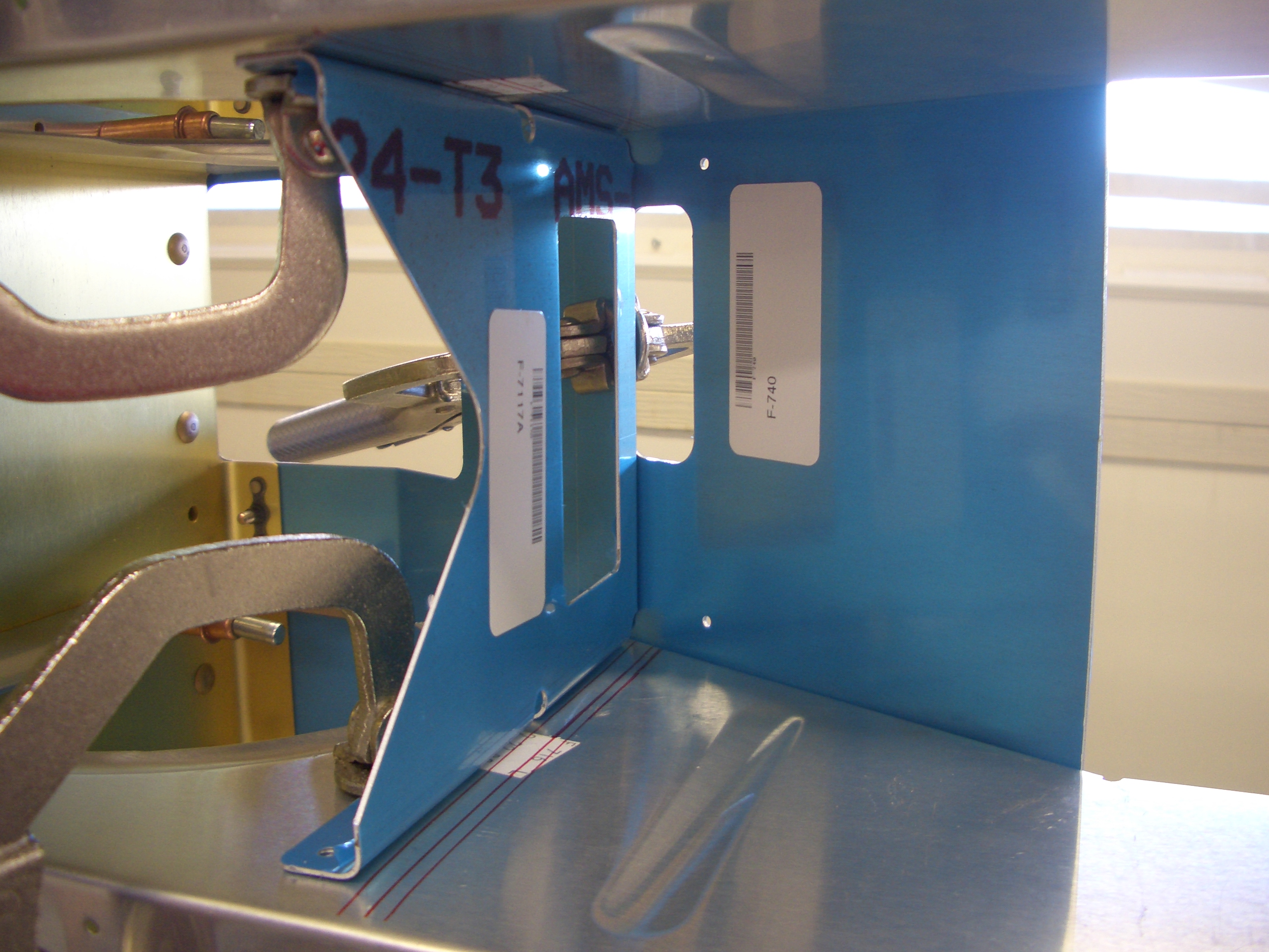
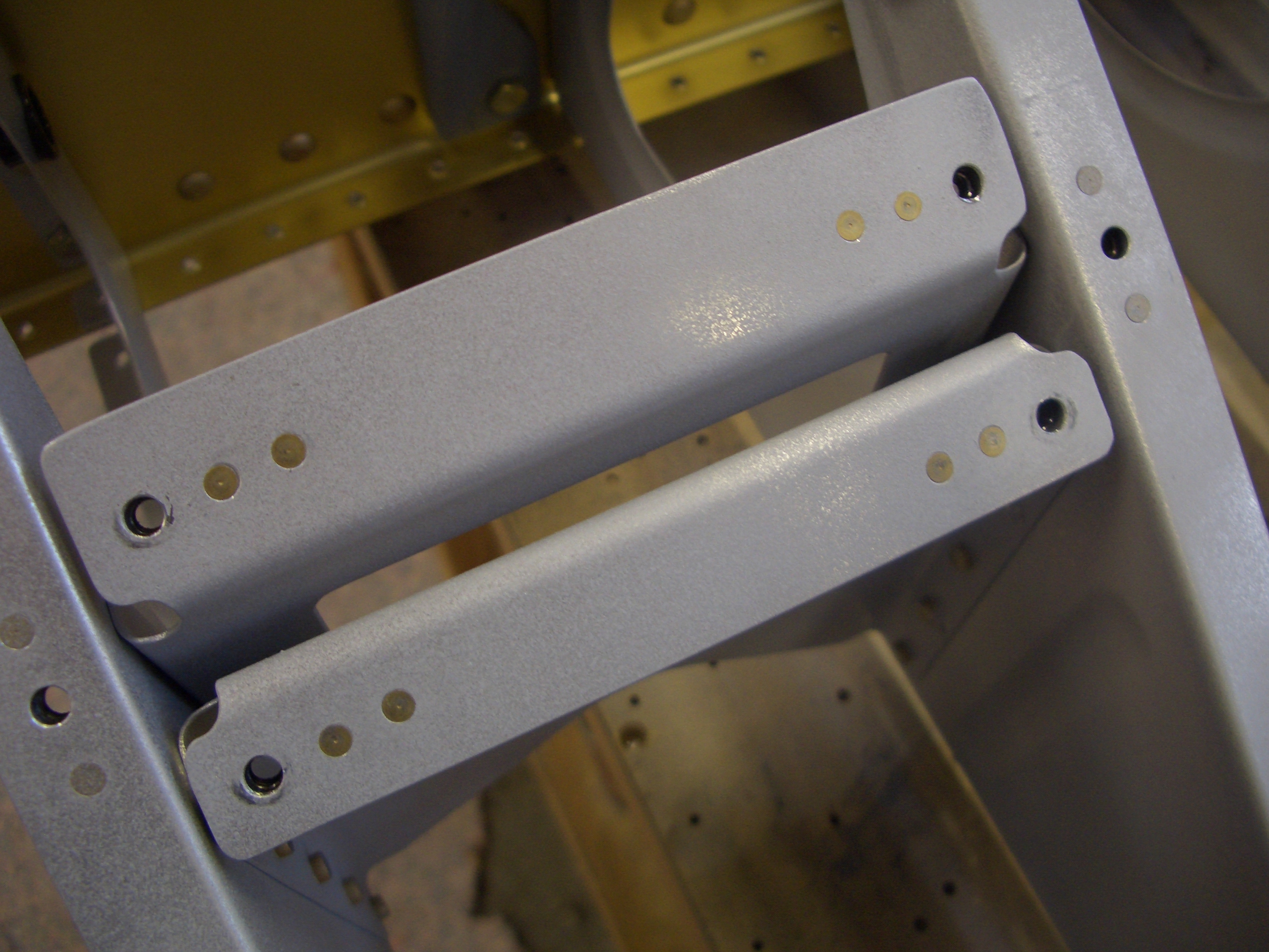
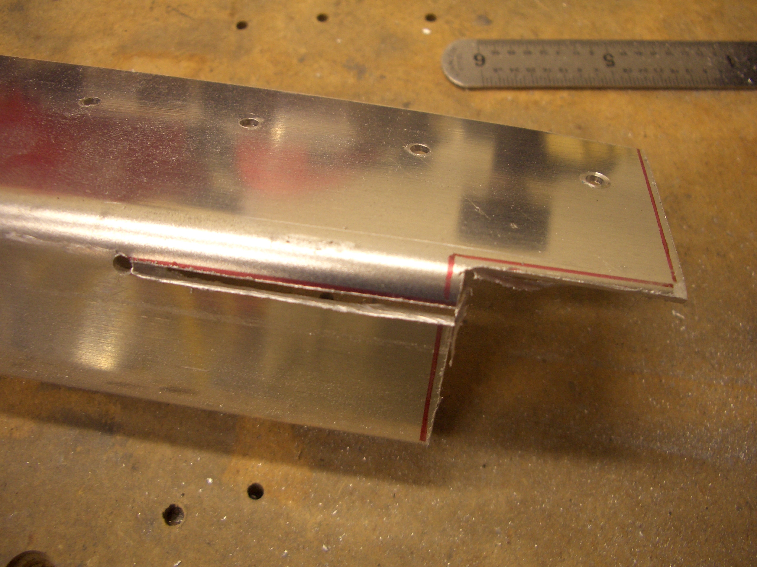
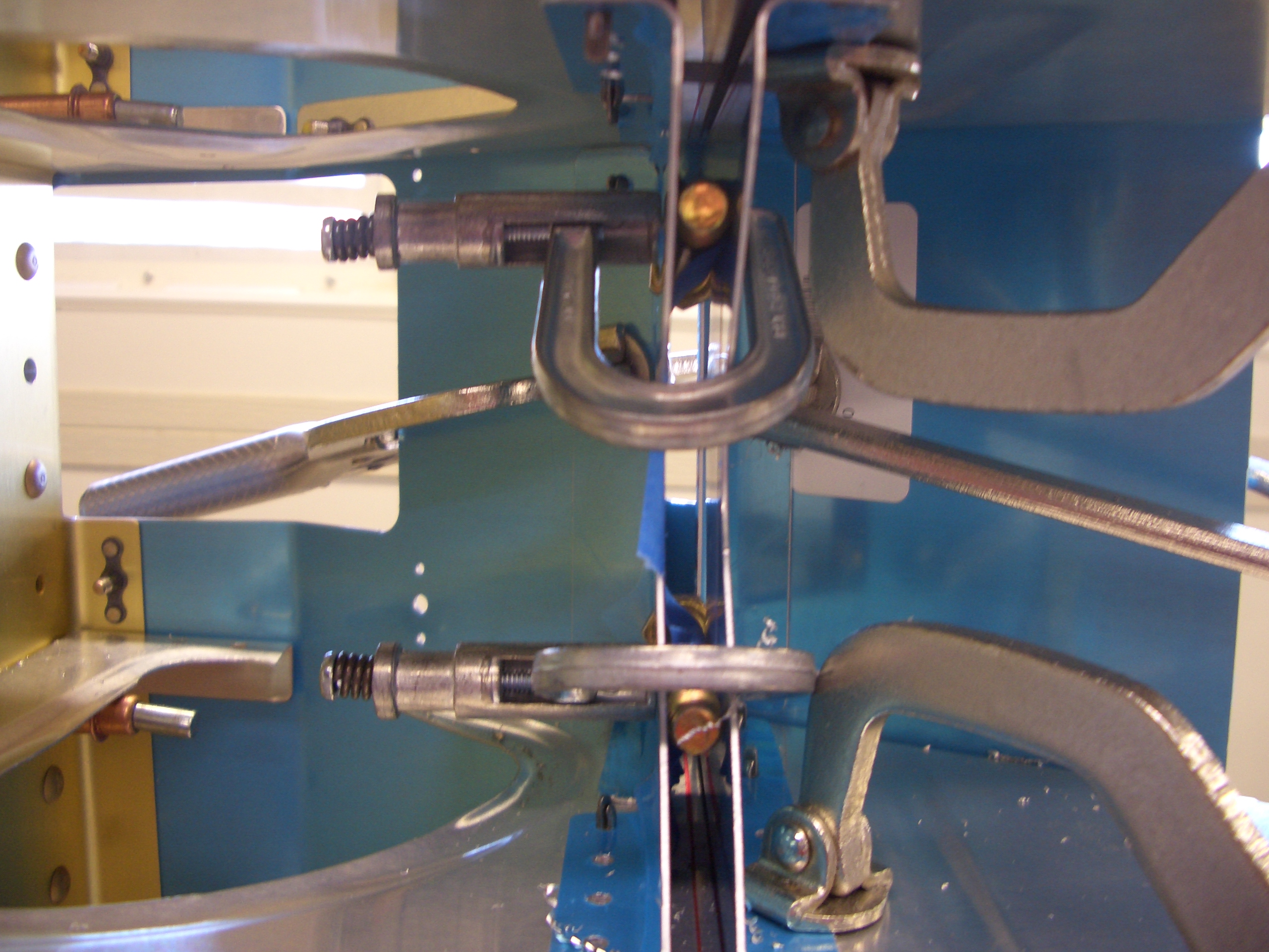
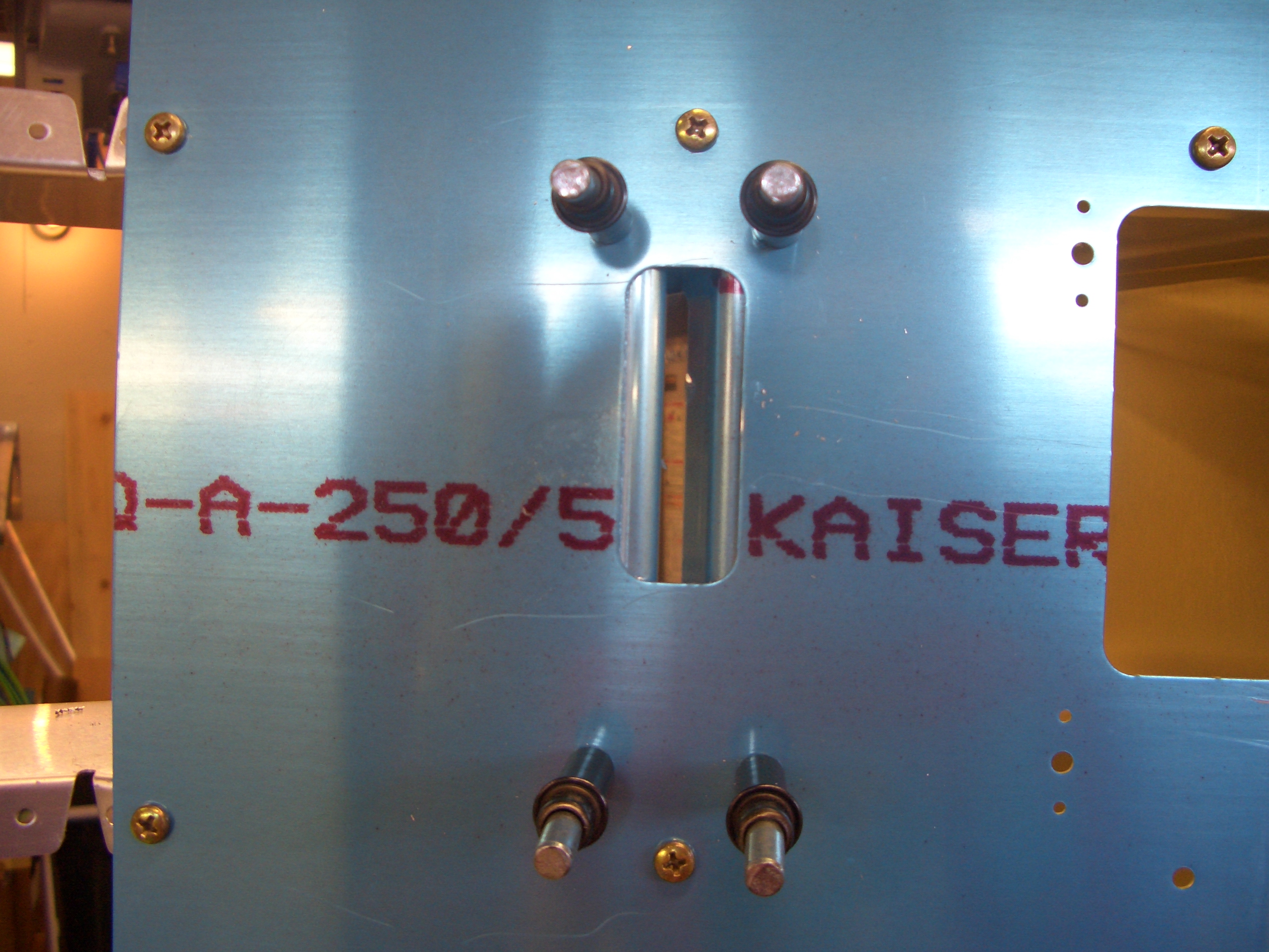
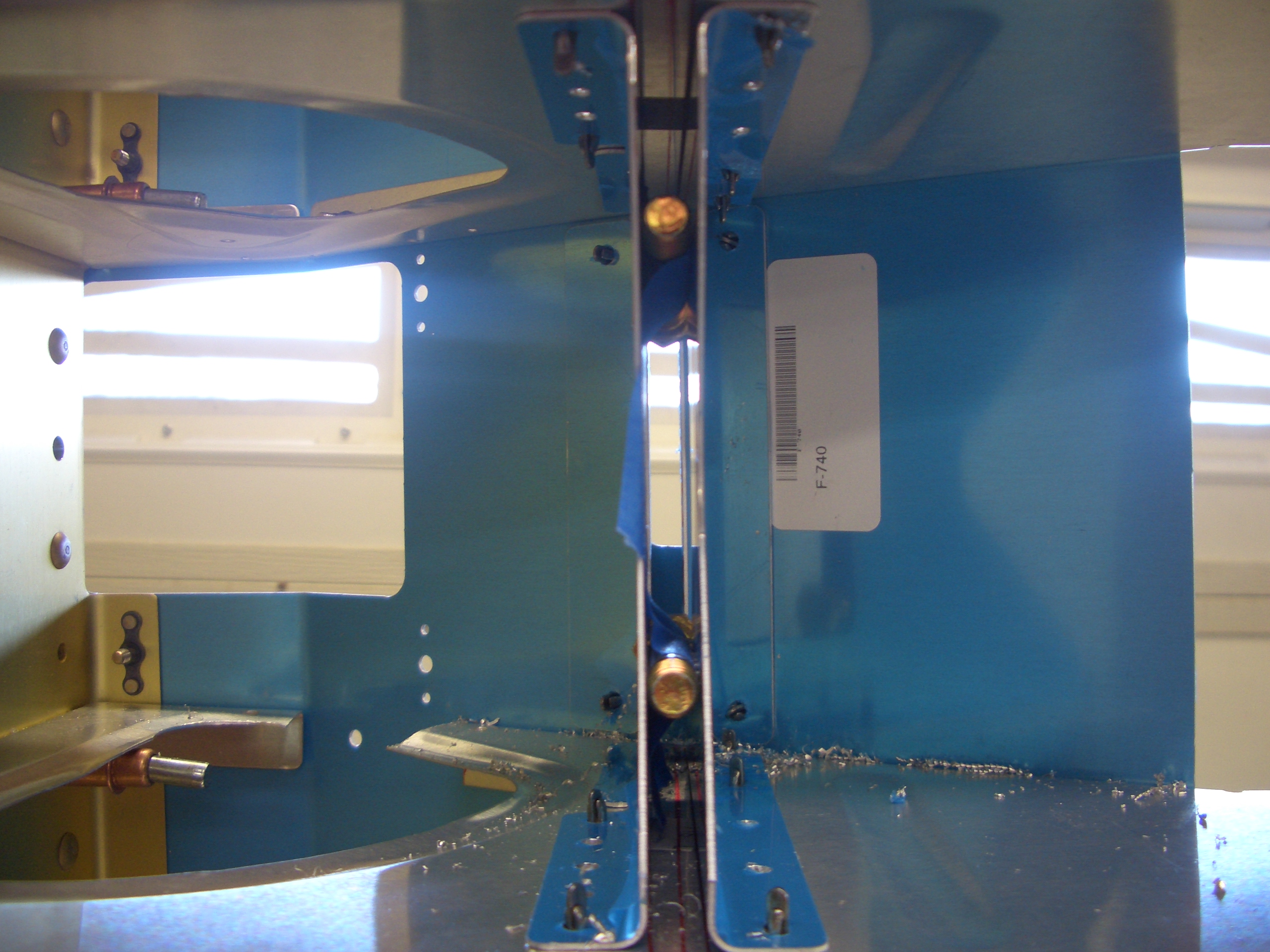
Instead of cutting a 5/16″ spacer, I just used a couple of AN5 bolts which are 5/16″ in diameter. I taped them in place and clamped the aft side of the bracket against the bolts and against the seat pan, then drilled the bracket to the adjacent ribs.
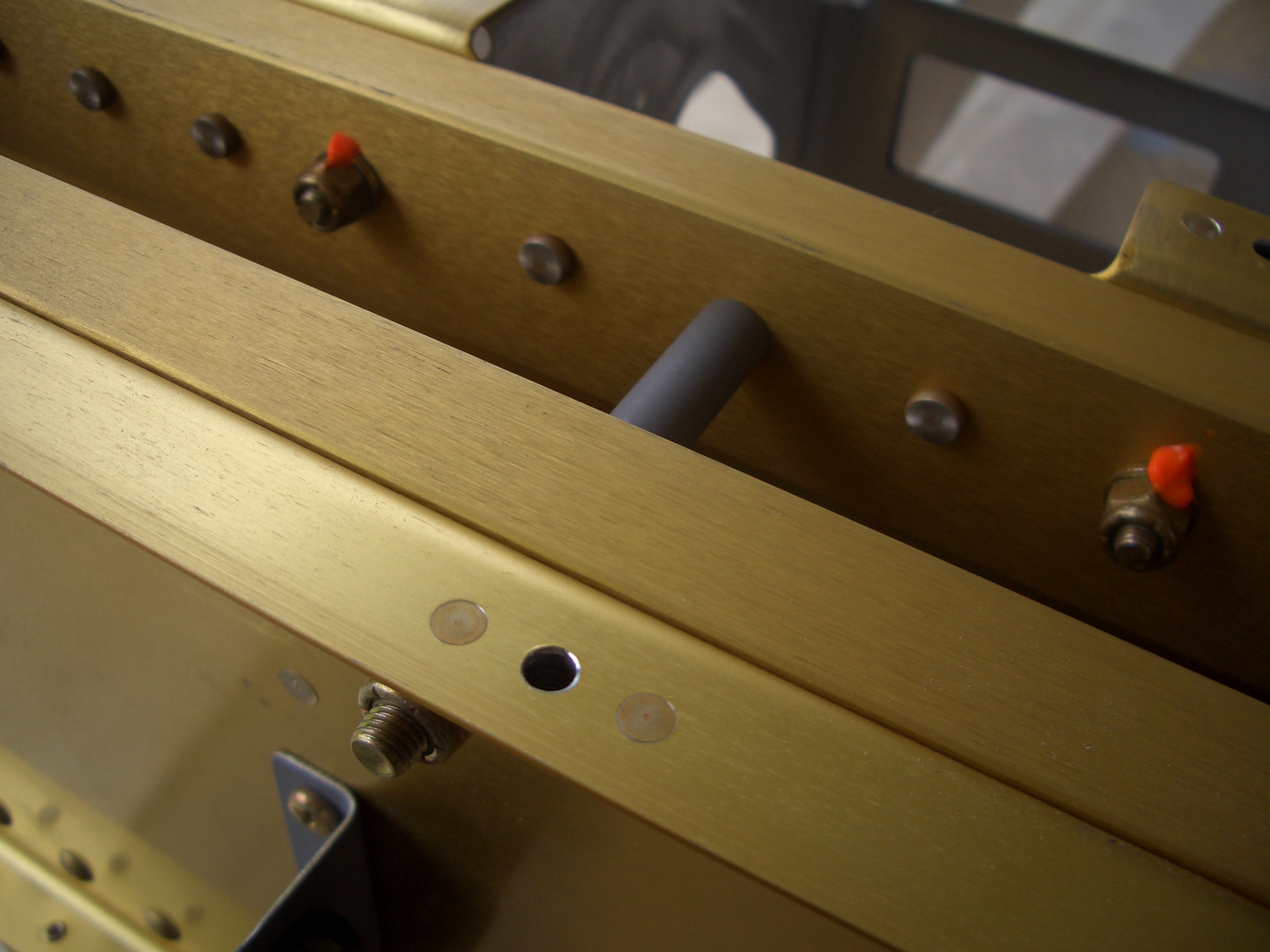
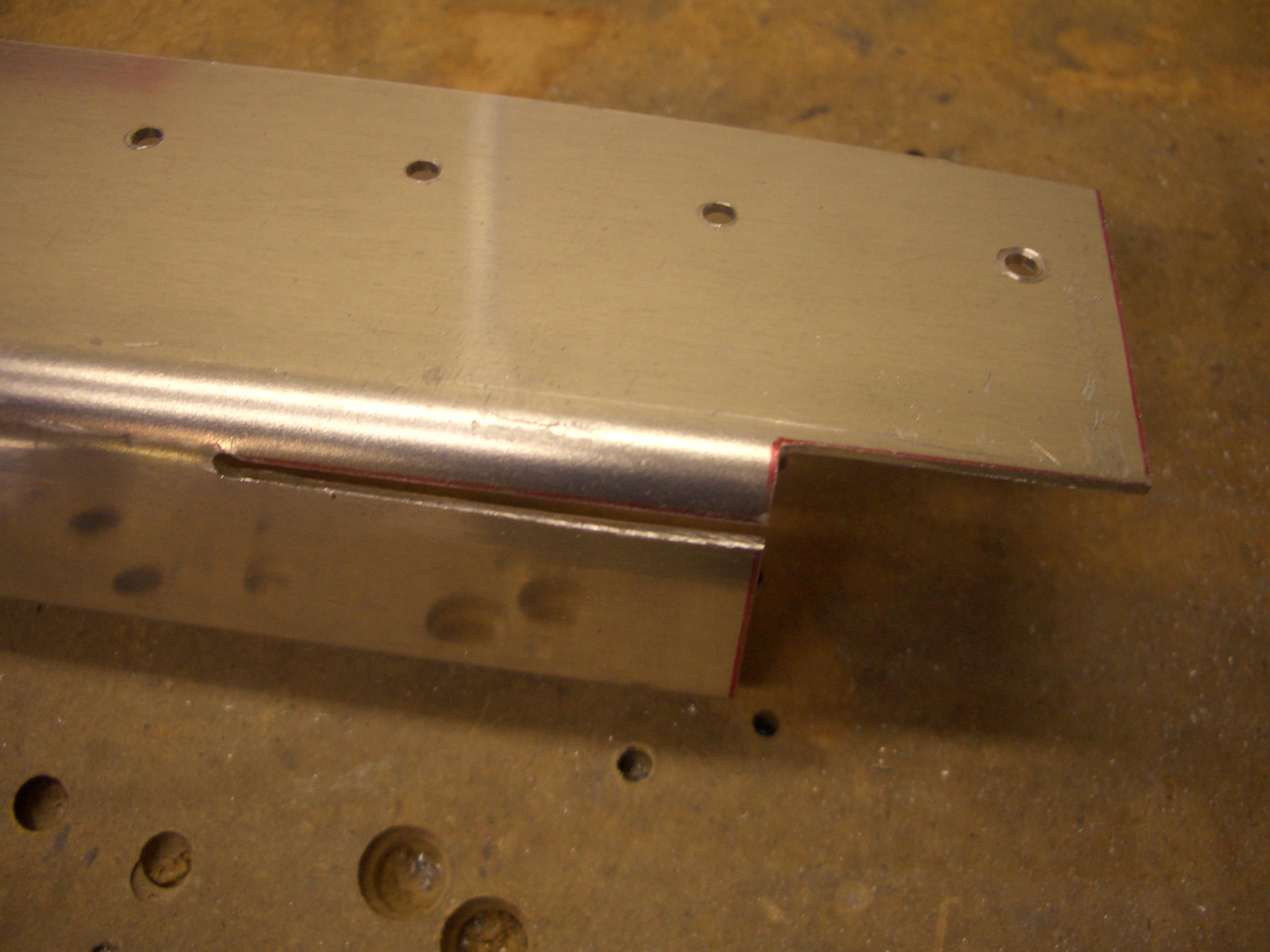
The prepunched holes in the seat pan need to be drilled to #19 for #8 screws.
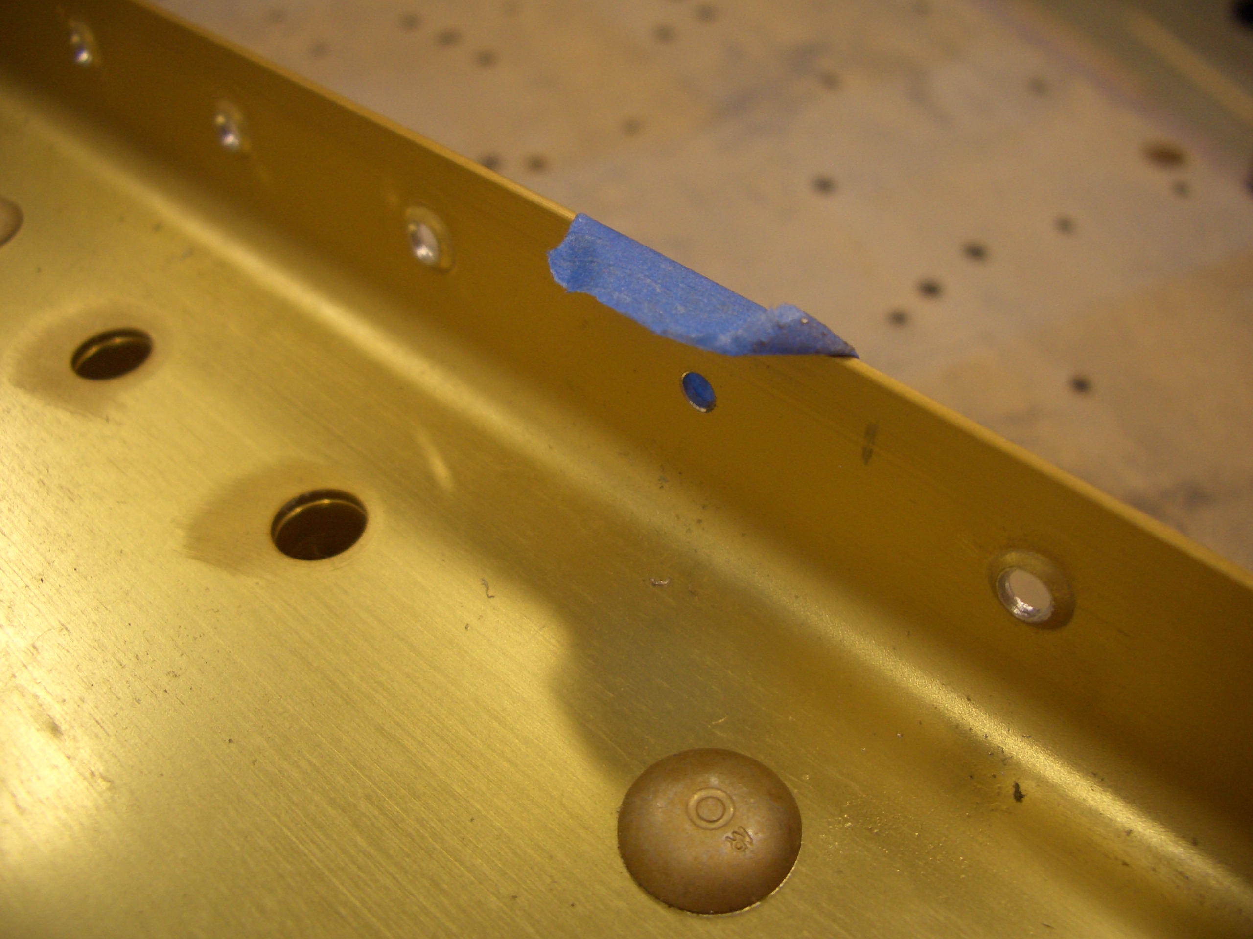
Here is the backside, showing good edge distance on the #19 holes.
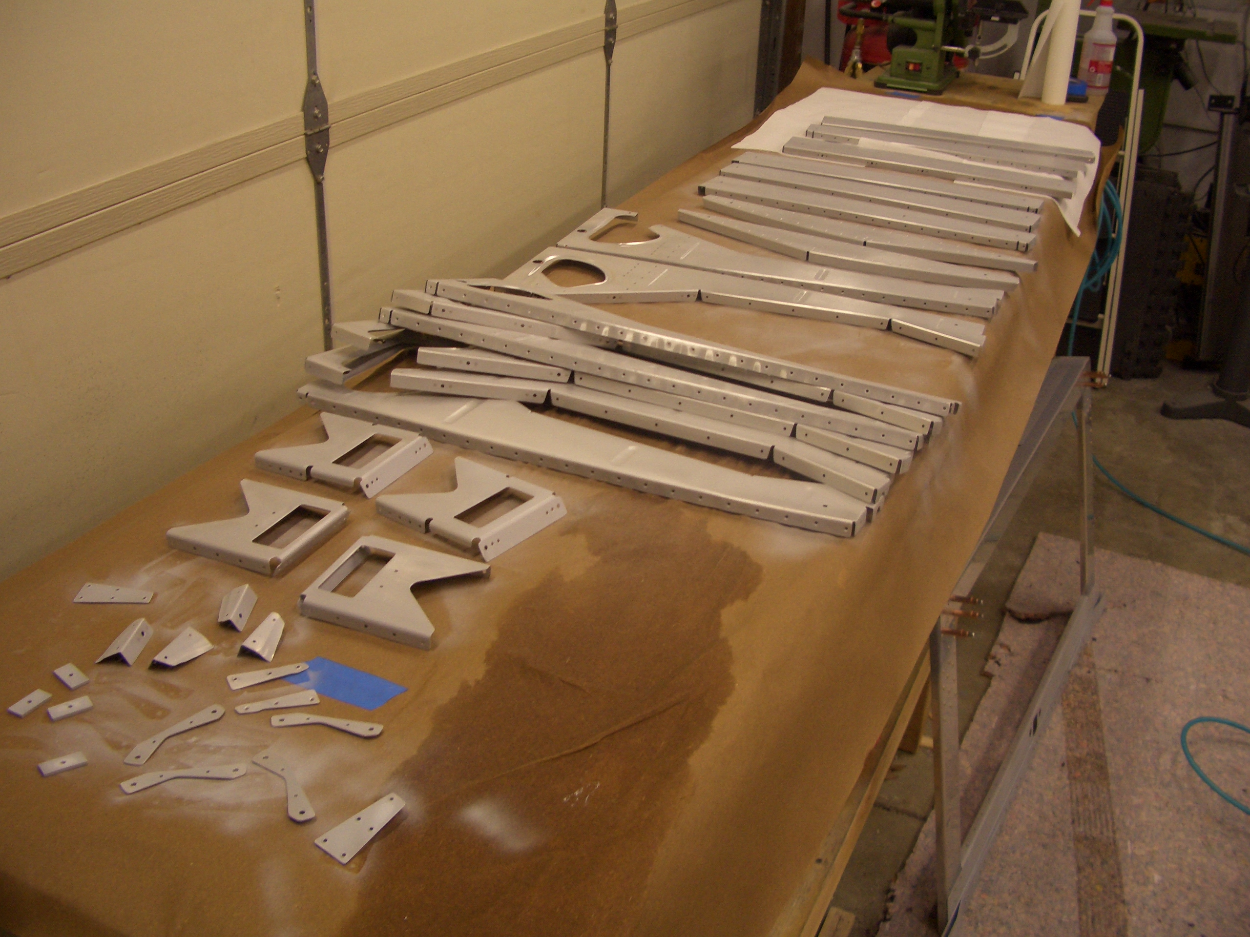
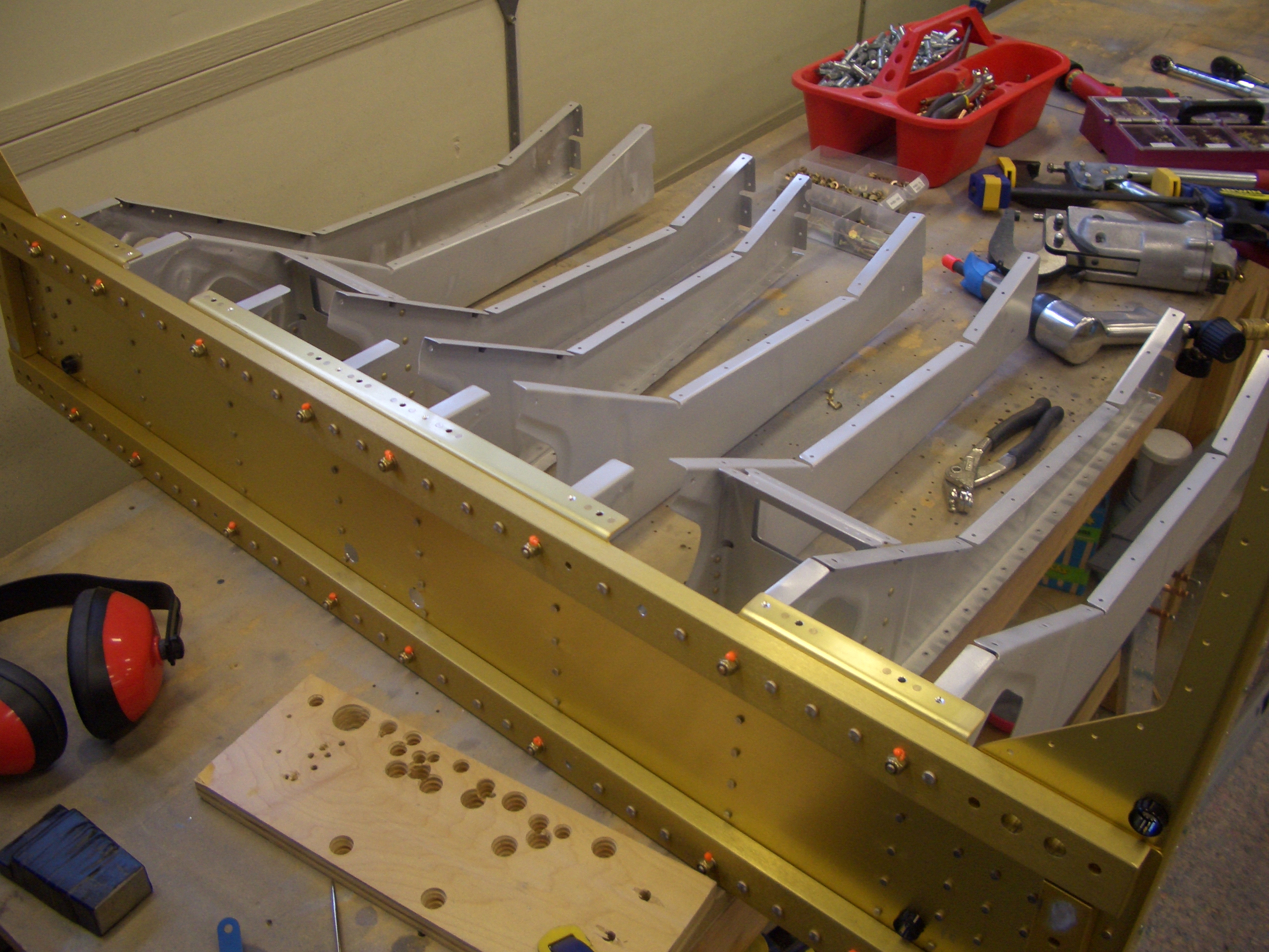
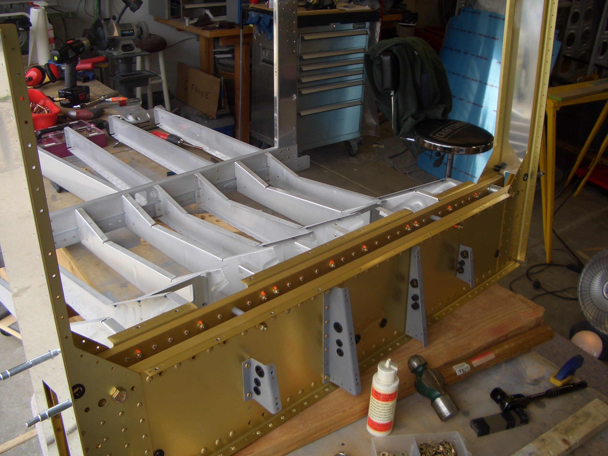
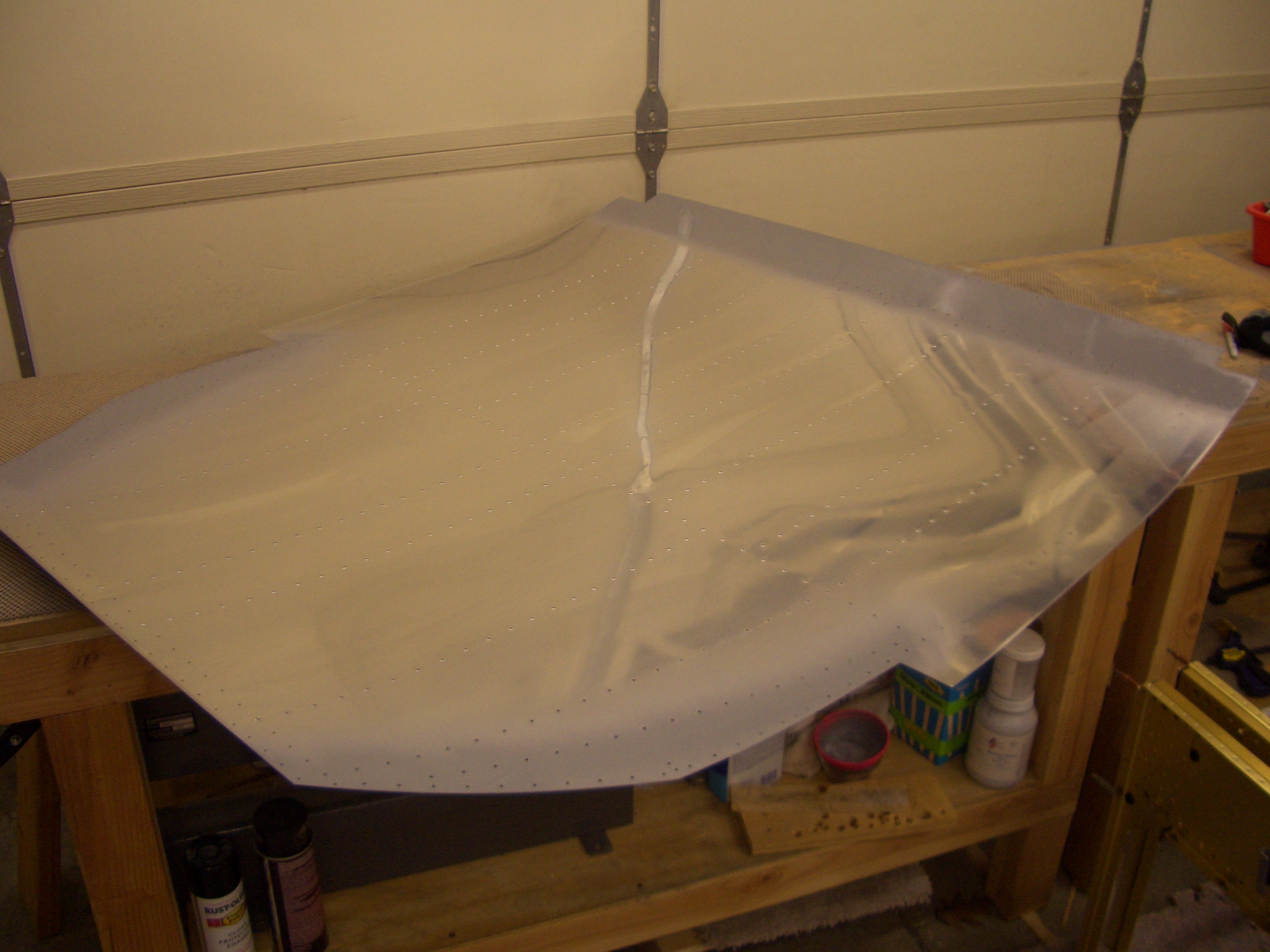
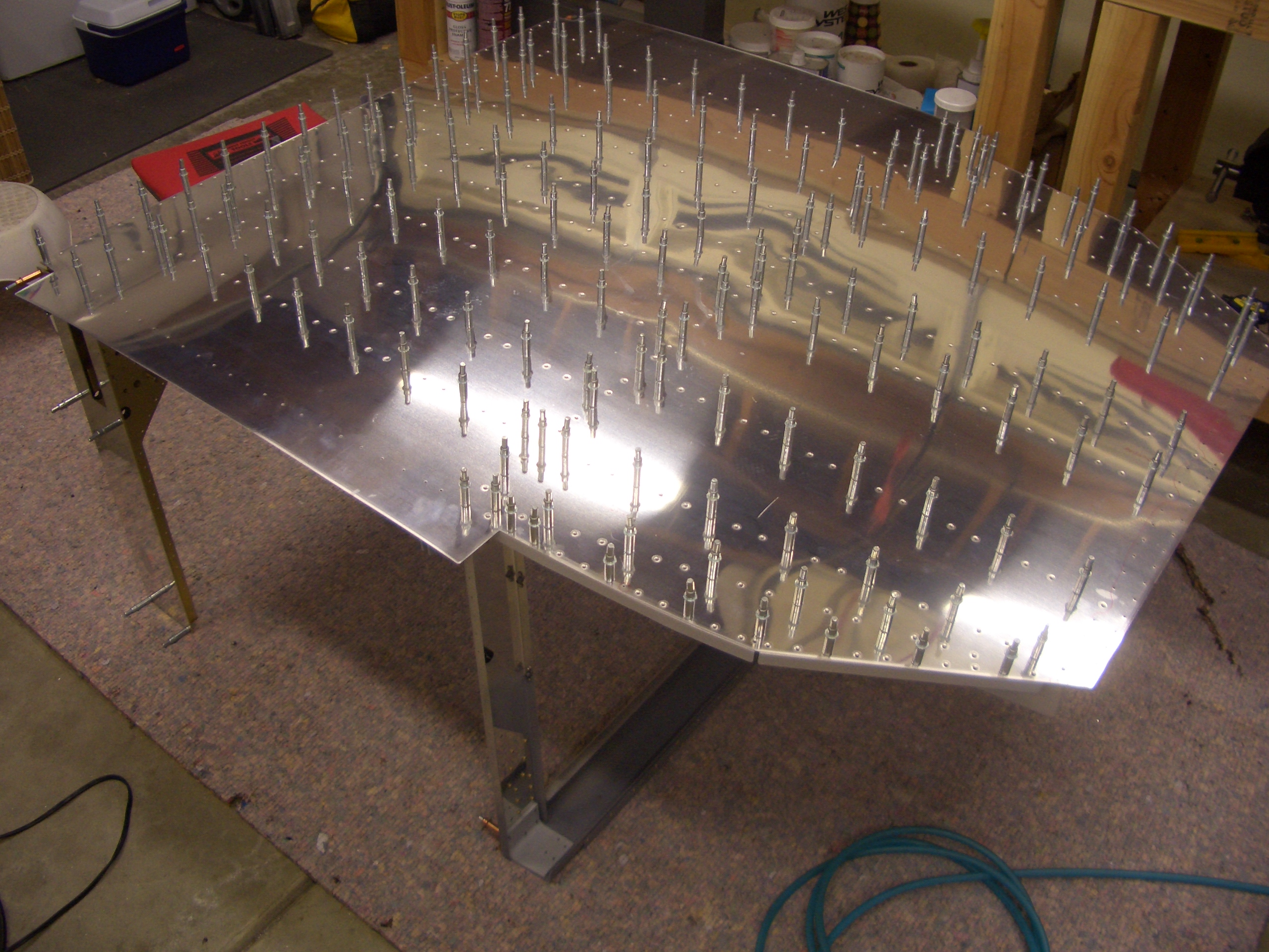
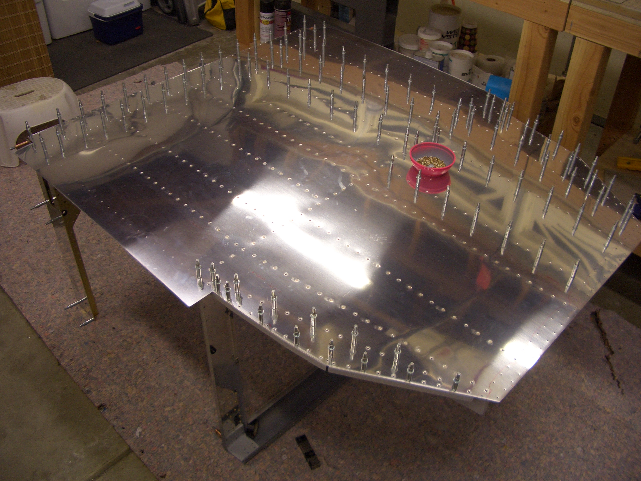
After repeating the process for the right bracket, I finished up a few remaining tasks such as drilling the seat ribs to the aft side of F-704, match drilling all ribs to bulkheads, and drilling out the forward tooling holes to 5/8″ for wiring runs. I then disassembled the center section and started prepping the individual components.
First up is to debur and dimple the holes in the bottom flanges of F-704. Remember that the holes we countersunk in the bottom skin have to be skipped when dimpling so that the floor stiffeners can lay flush against this flange.
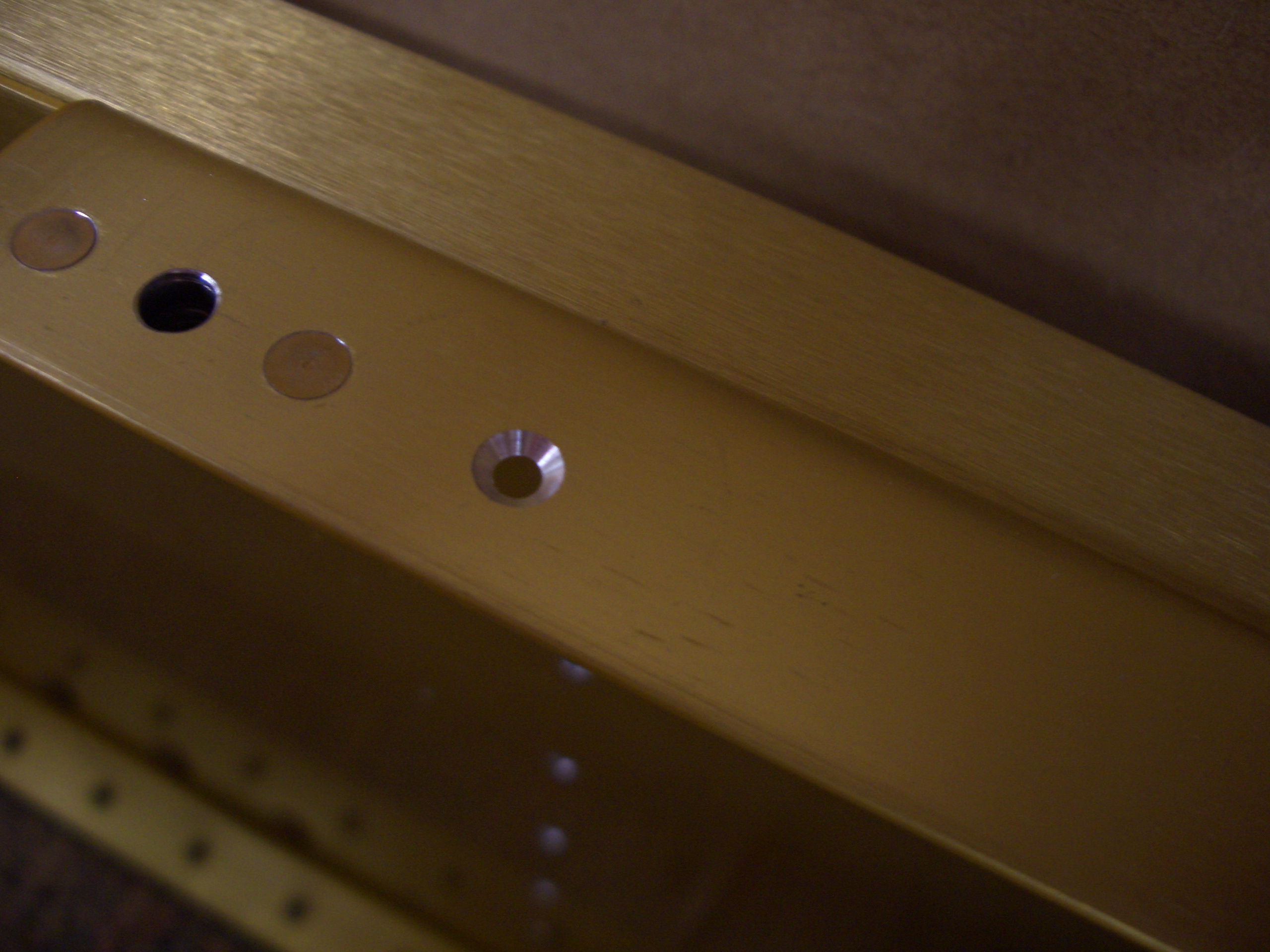
Neither the instructions nor the plans make any mention of these holes in the top flange of the aft side of F-704, but the seat pan that sits above this is removable, so this must just attach the top of the seat ribs to the F-704 flange. Since the seat pan needs to sit flush against this flange, I countersunk this for an AN426AD3 rivet.
Finally, I started deburring all of the components. I made it through the F-704 and F-705 bulkheads and six of the eight seat ribs before running out of steam. I should be able to finish deburring the rest of the center section components tomorrow.