Riveted Aileron Braces, Installed Aileron

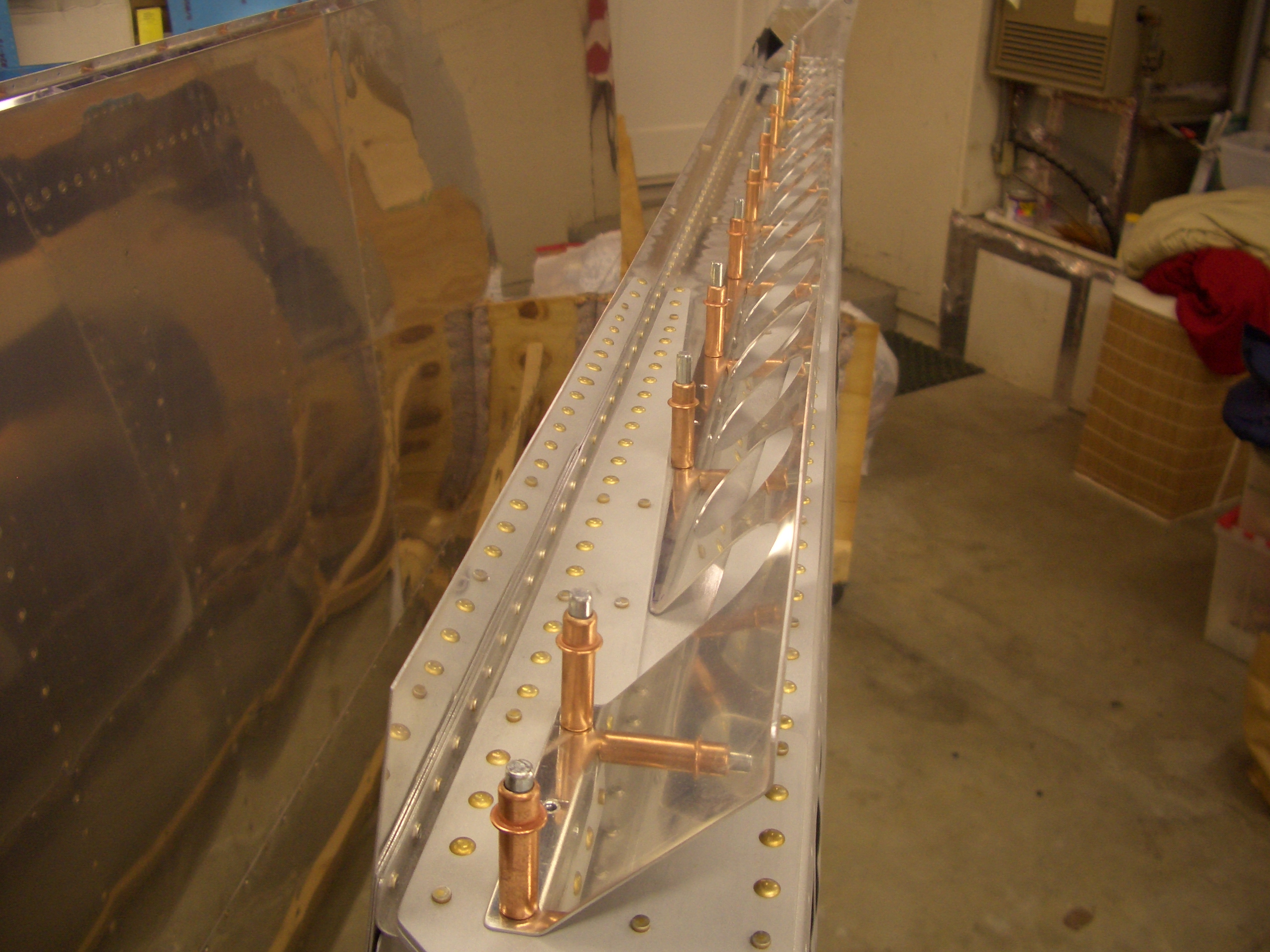
I installed the aileron braces tonight.  All of these rivets could be squeezed, so I could do this after the kids went to bed without making too much noise.

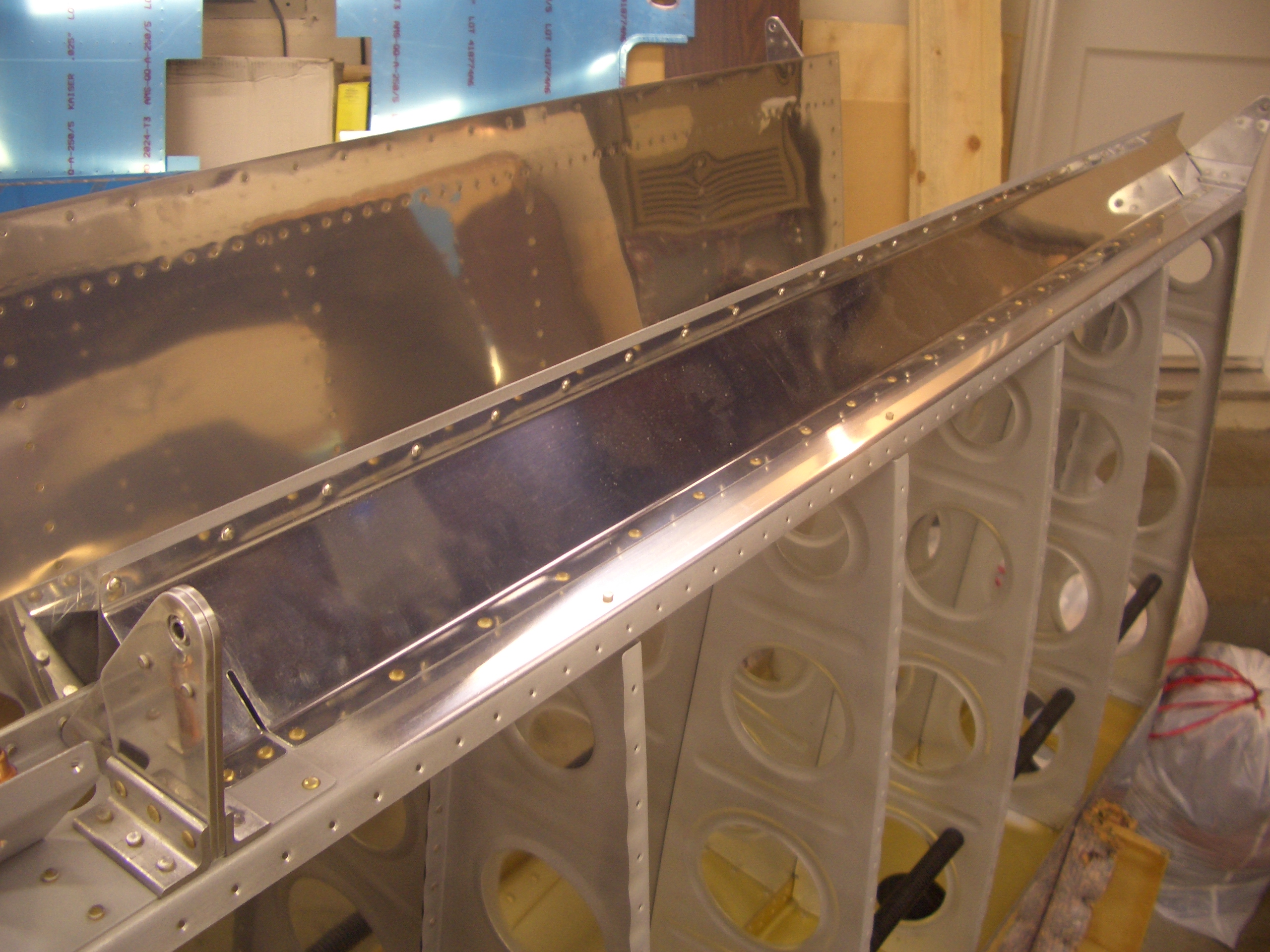
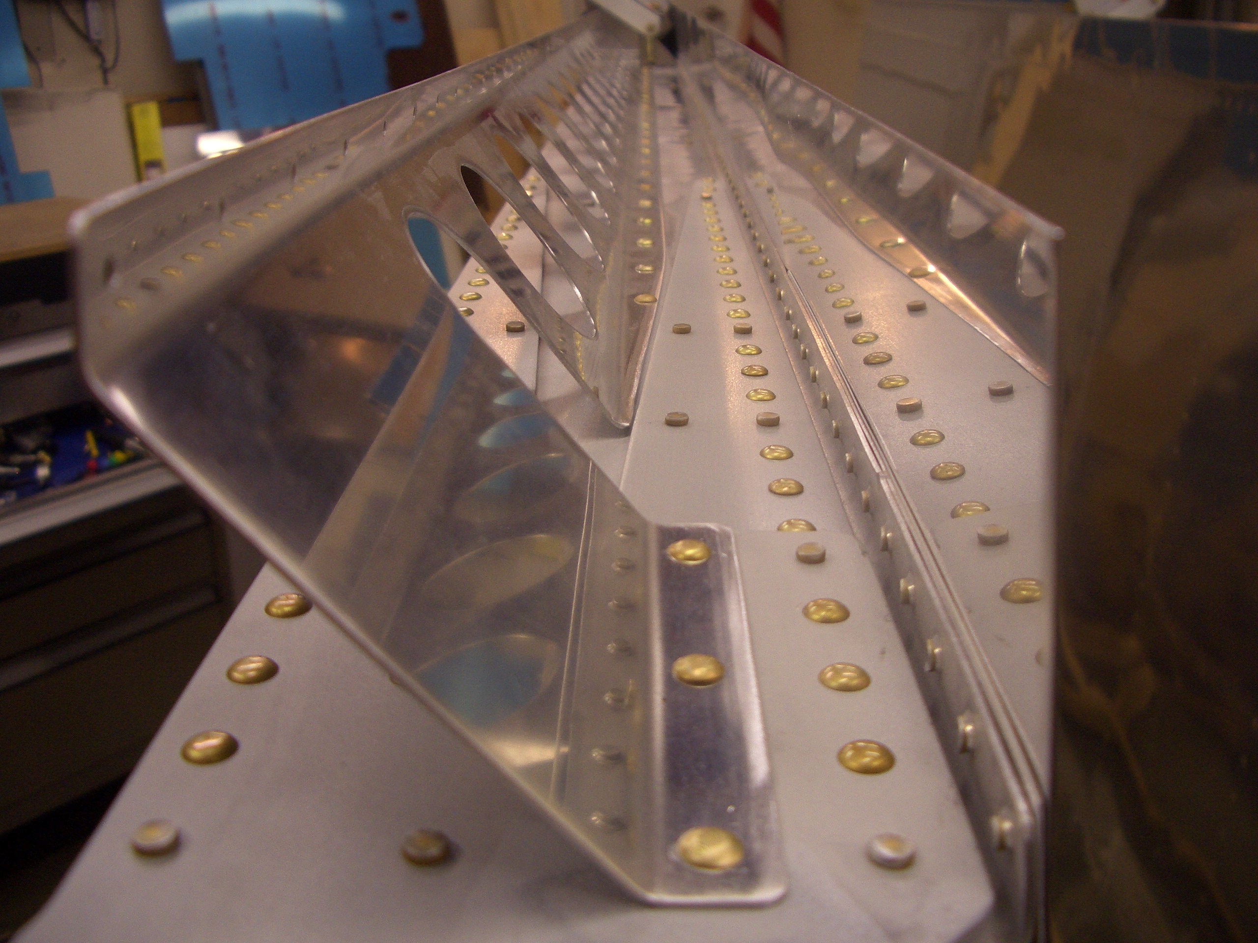
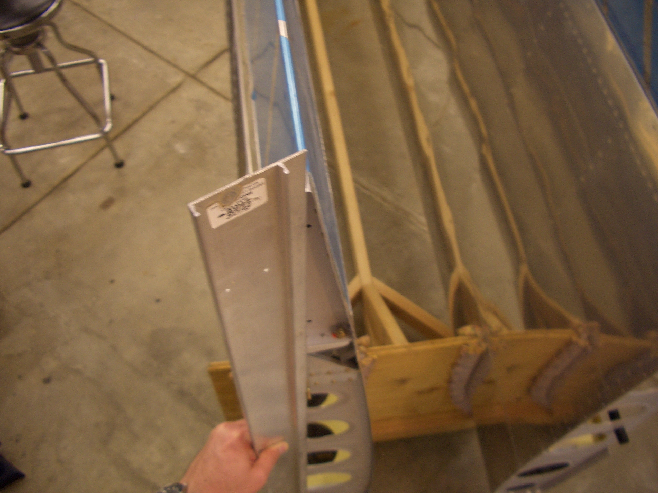
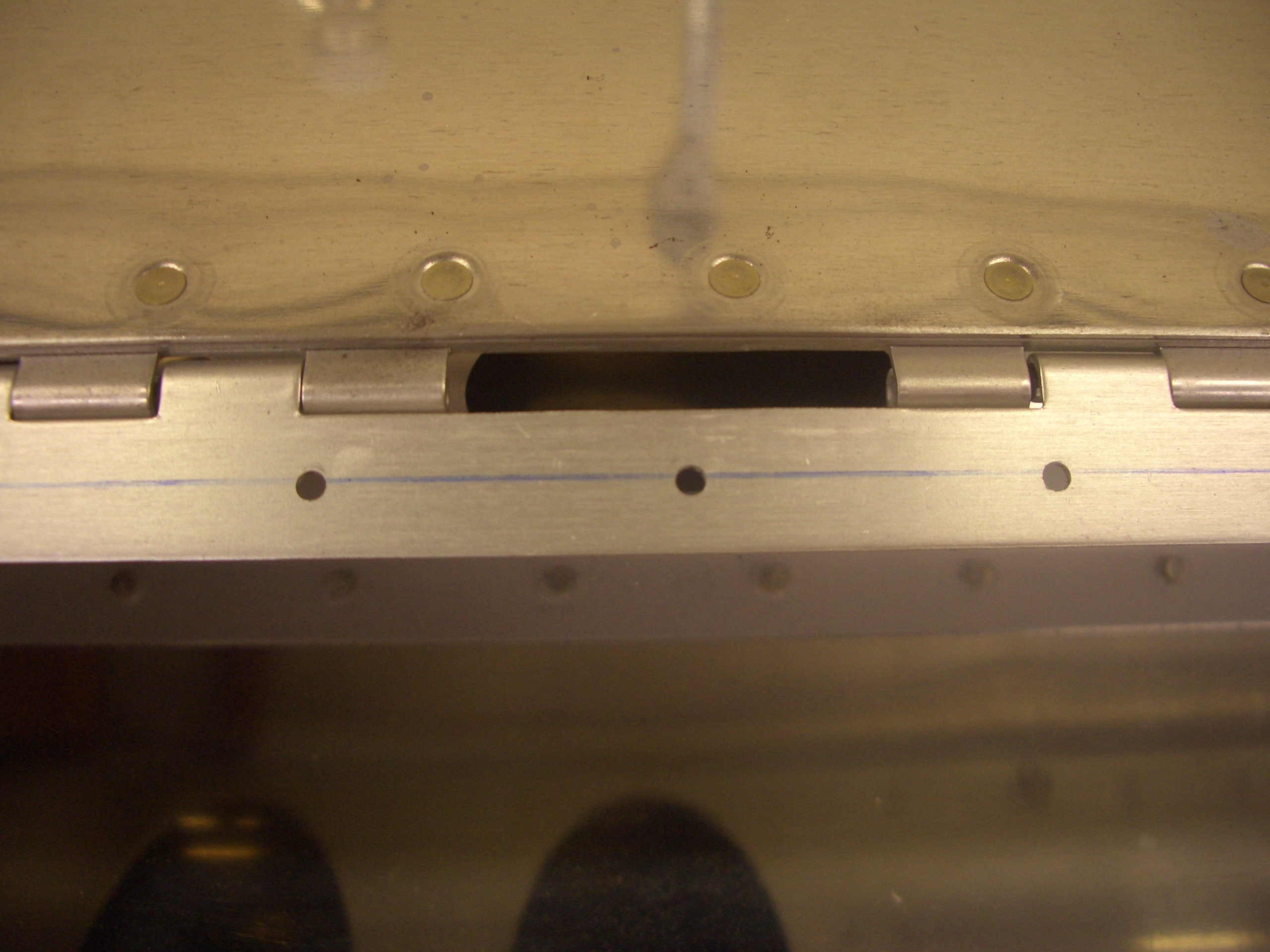
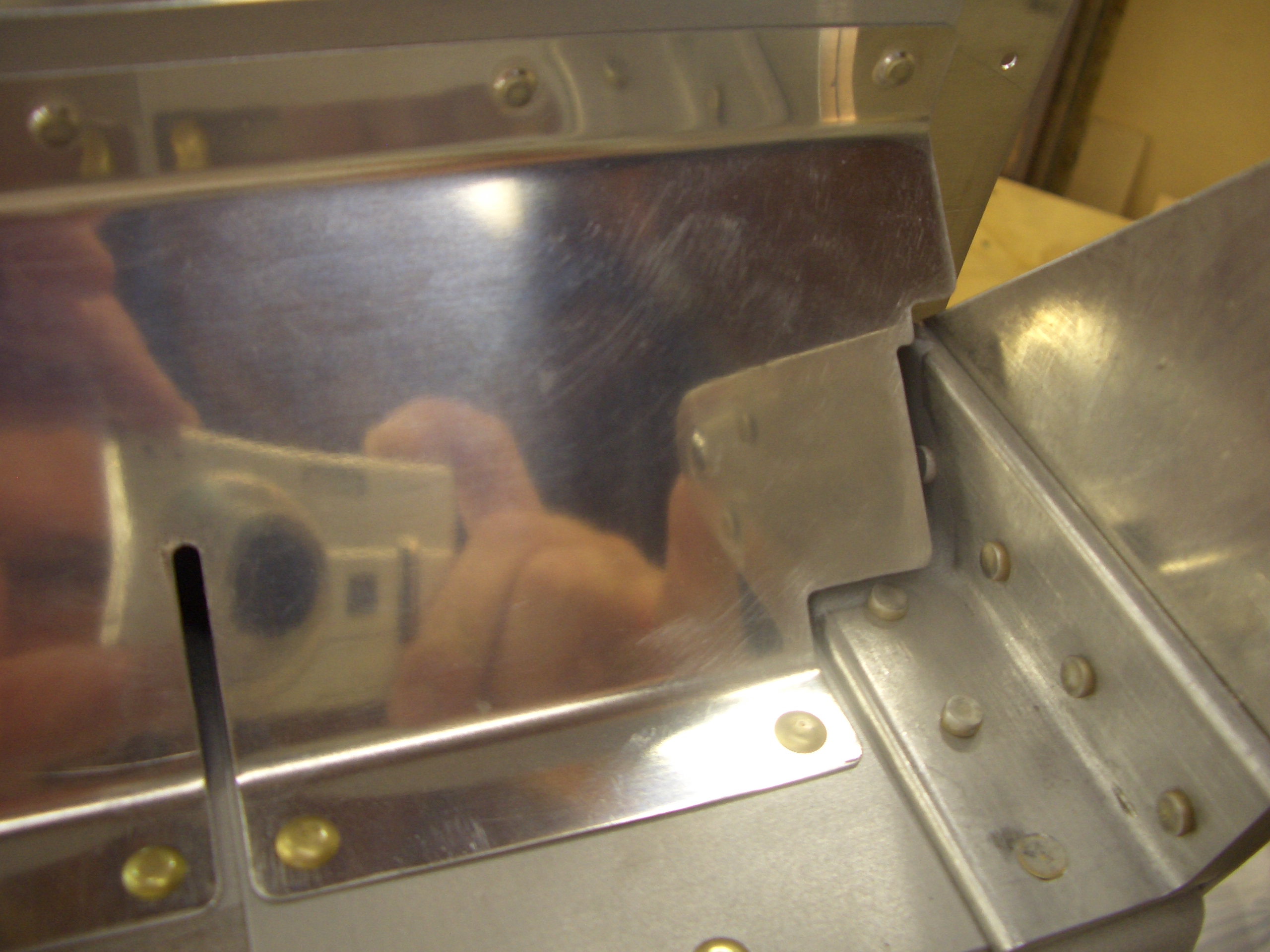
Here is a closeup of the outboard part of the flap brace.  The relief cut on the left allows the brace to step up onto the rear spar doubler, and the complicated shape on the right allows it to follow the outboard aileron hinge bracket closely.  The brace is riveted onto the rear spar with universal rivets, but is riveted to the top skin with AN426AD3-3 rivets which are the shortest rivets I’ve had to use on the project so far (and I assume the shortest I will have to use).  I assume these rivets are so short so that there is clearance here for the aileron.

I also clecoed on the flap brace, but couldn’t rivet it on because these will have to be shot and bucked since the brace blocks access with the squeezer.

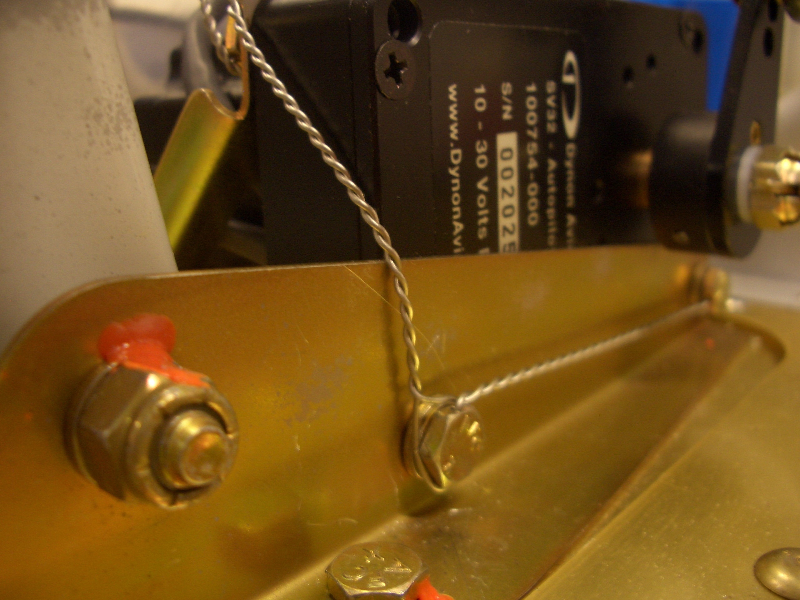
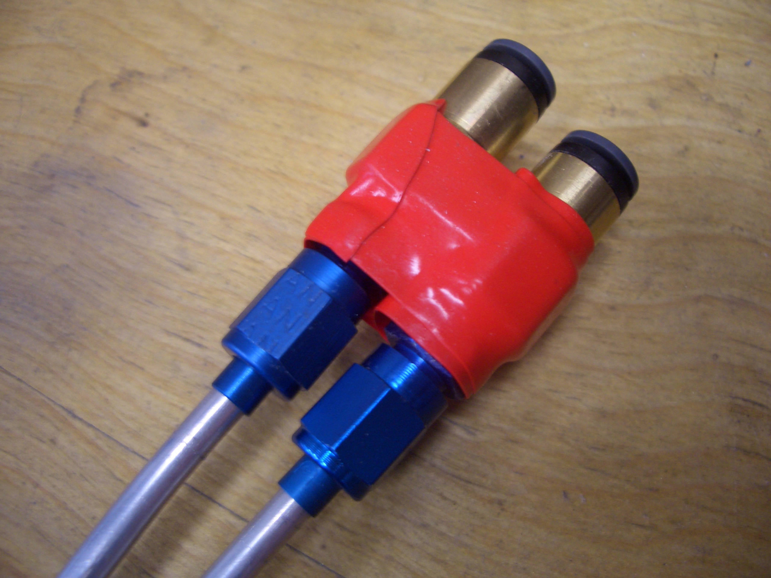
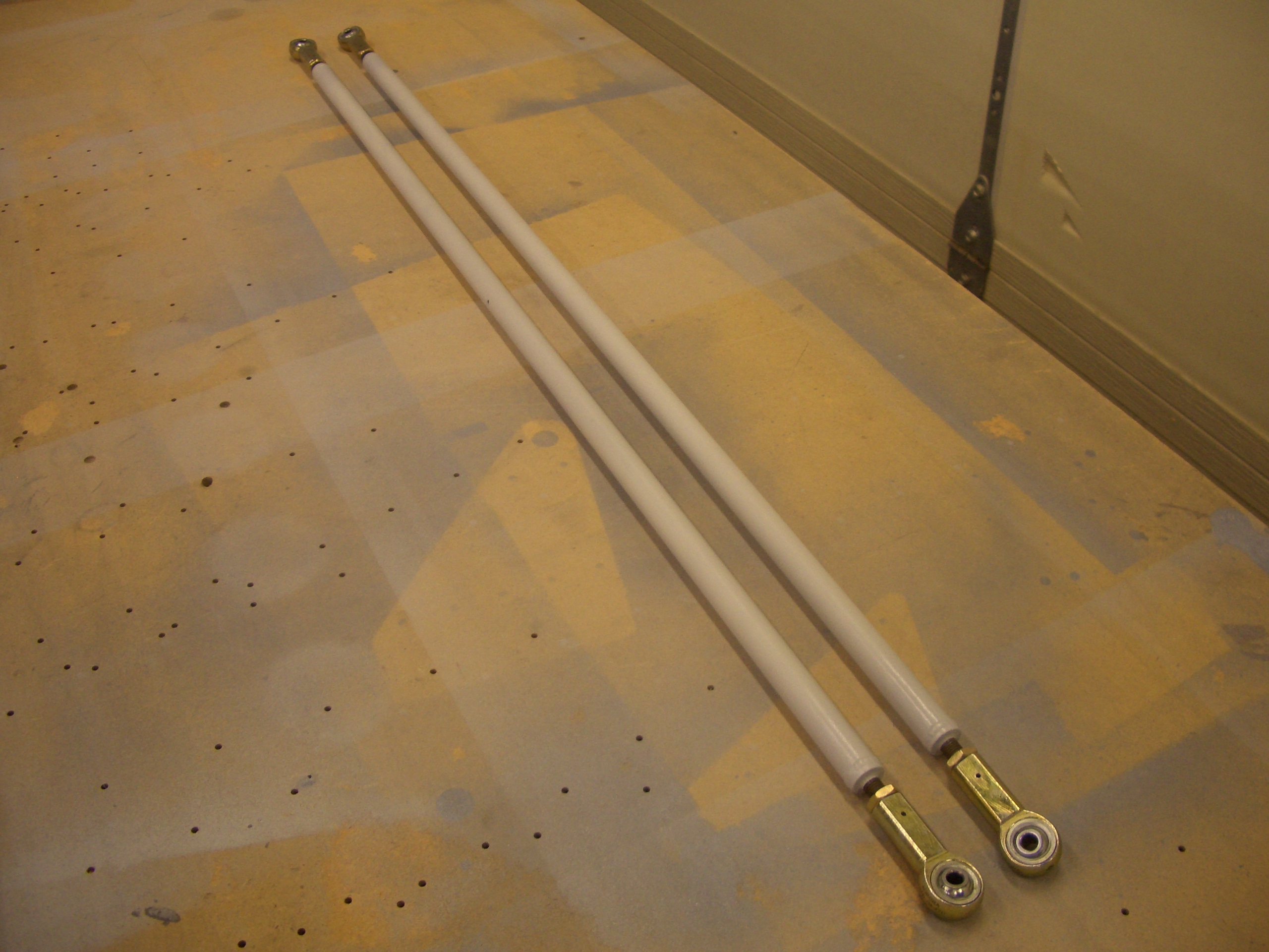
I assembled the rear pushrods.  The jam nuts are not torqued down yet since I will have to adjust these to final length once they’re installed.

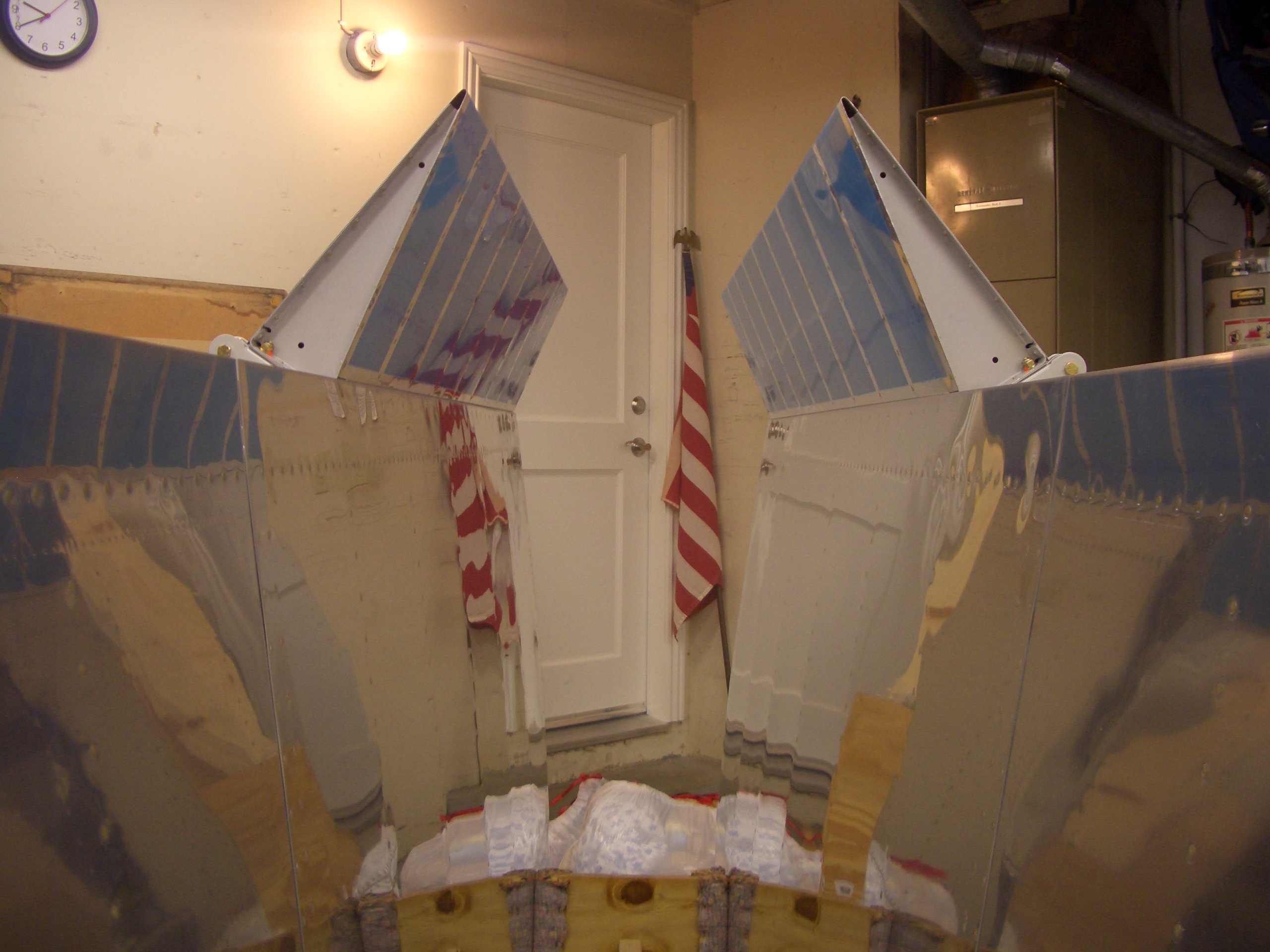
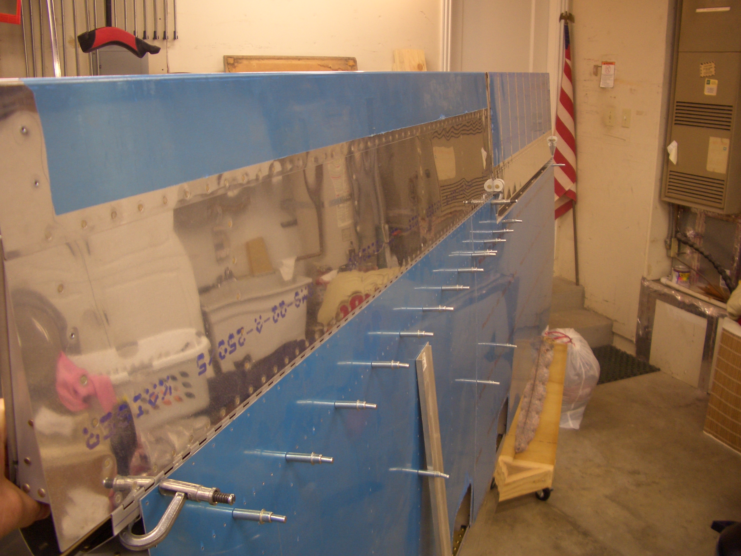
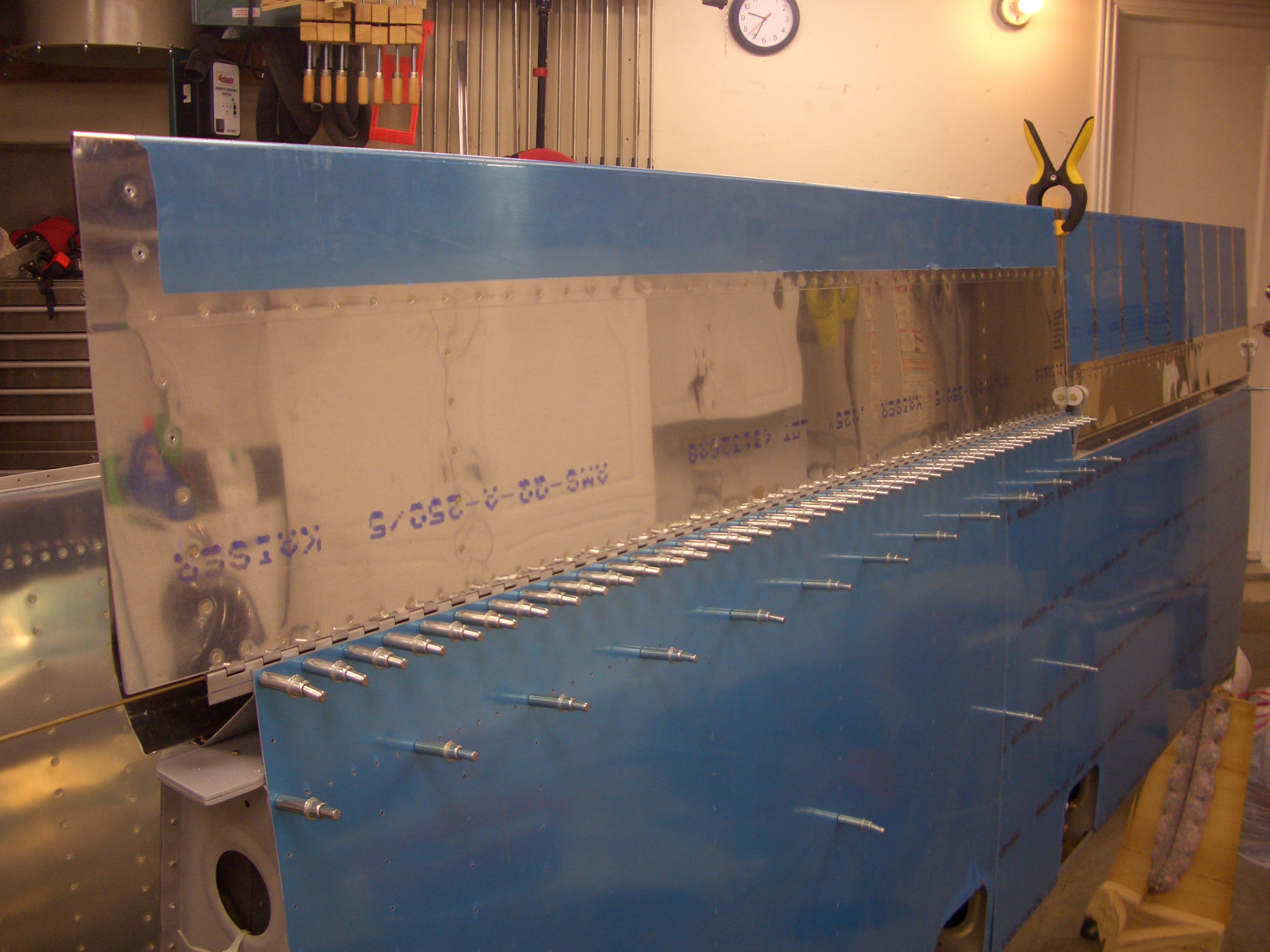
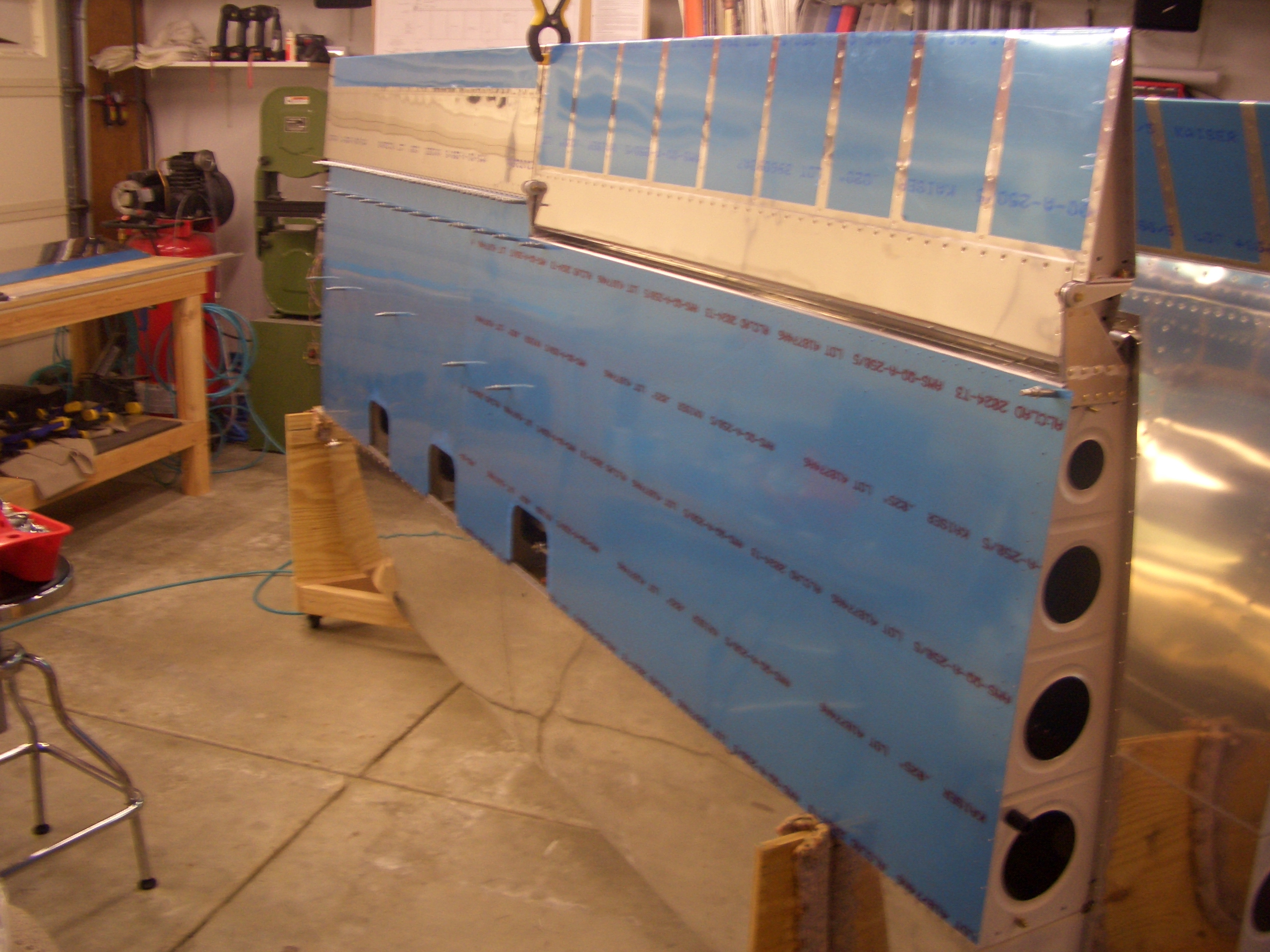
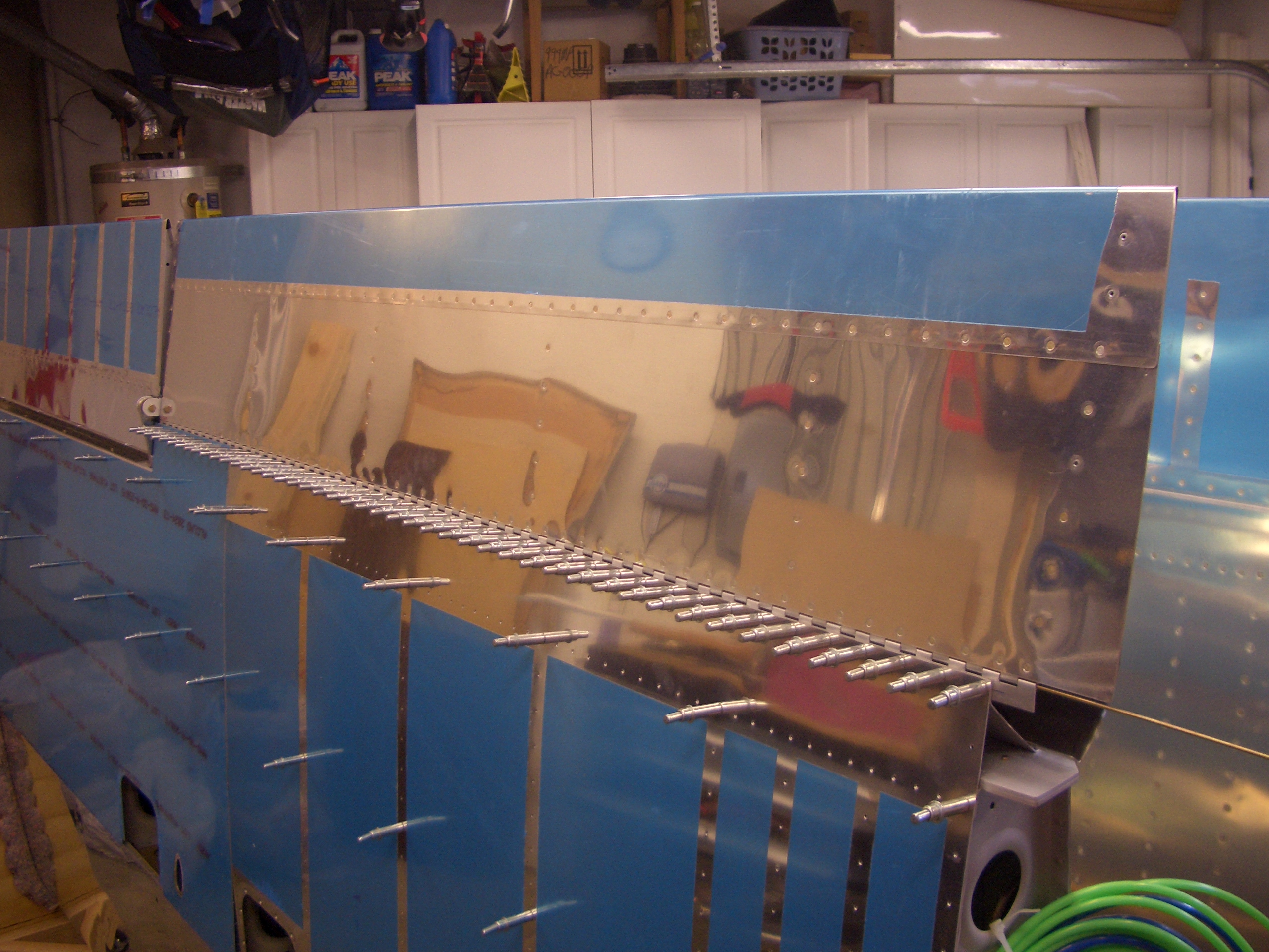
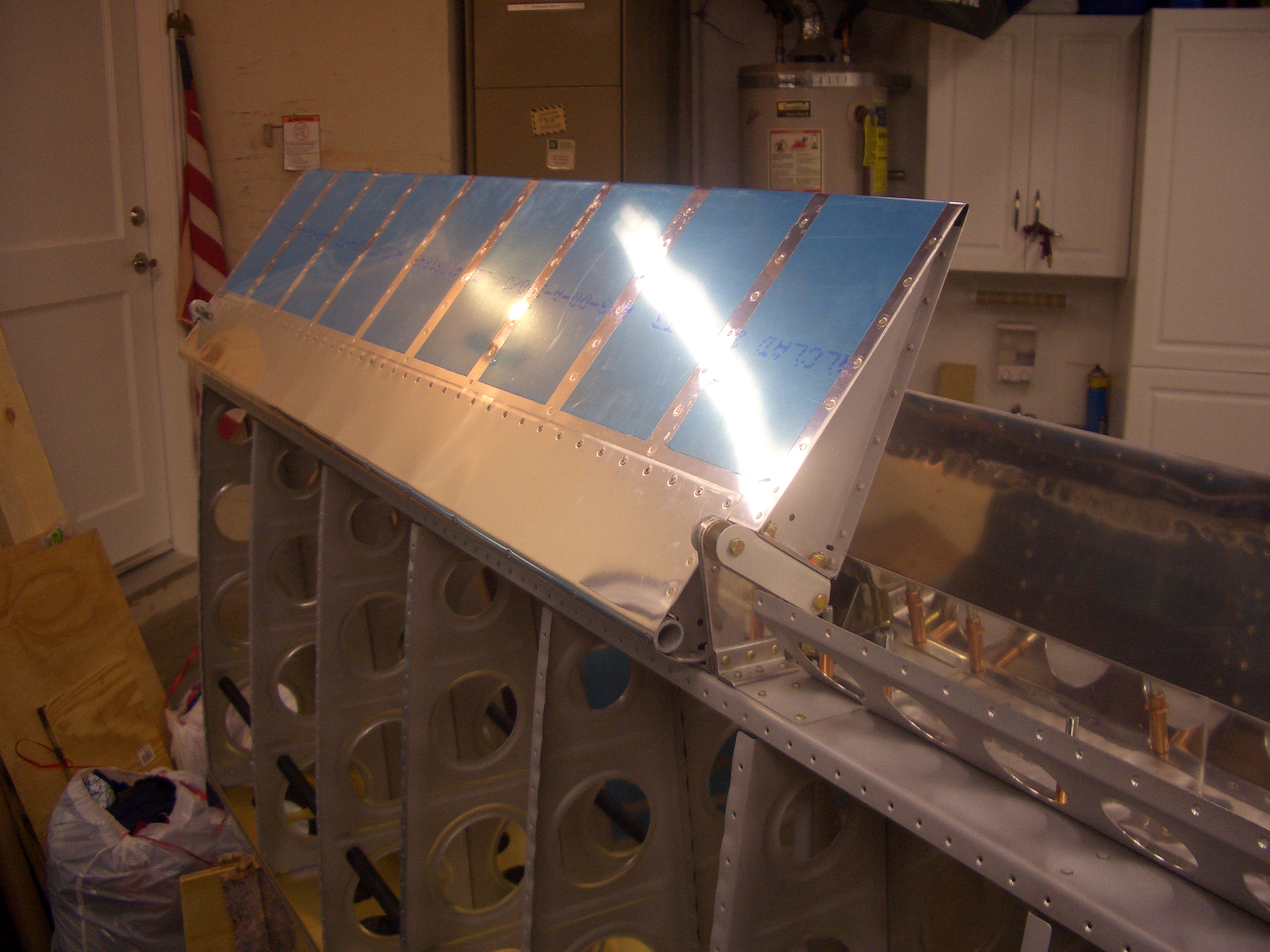
I went ahead and loosely installed the left aileron on the wing.  None of the bolts are tightened down since this may have to come back off at some point.

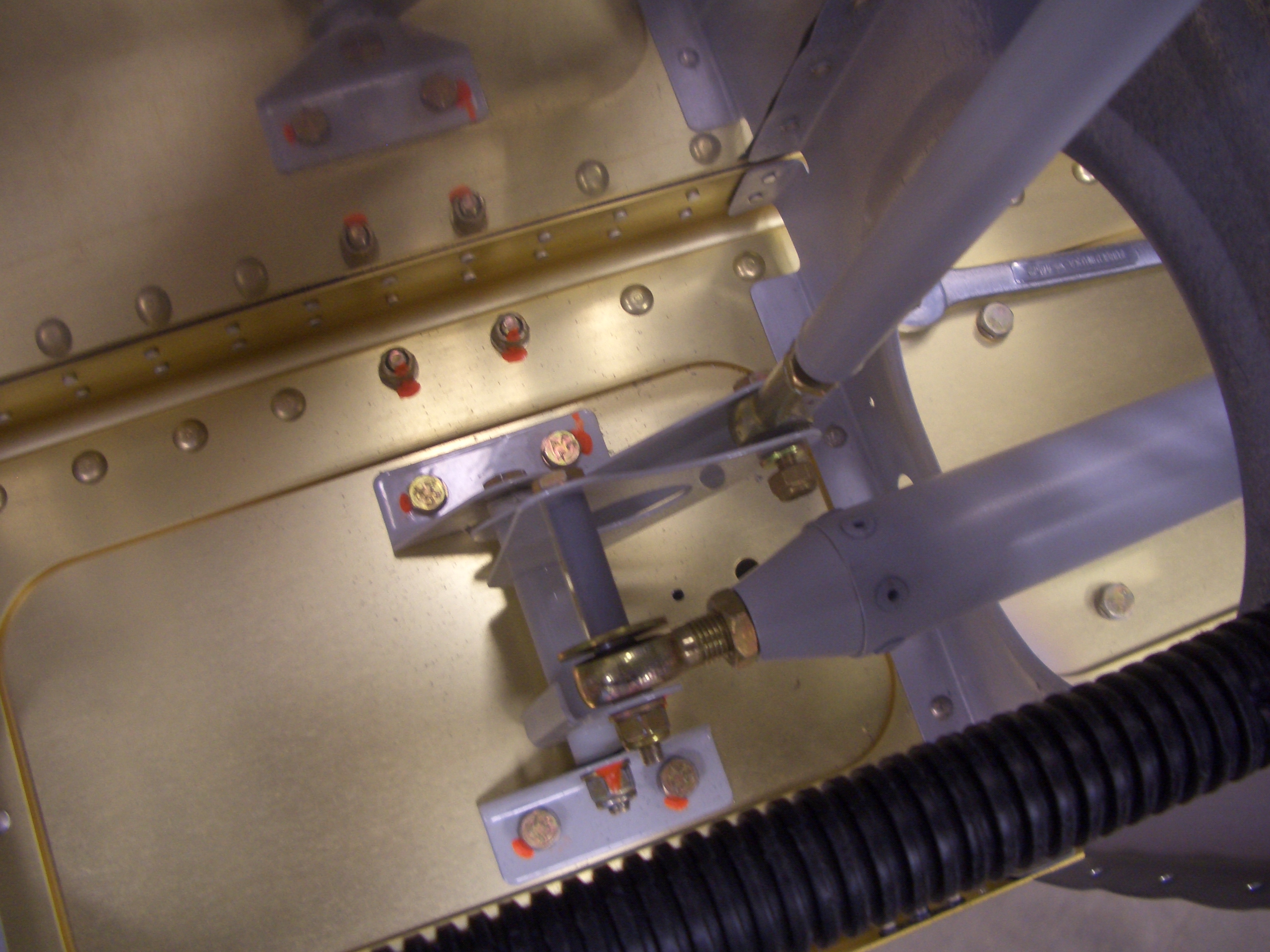
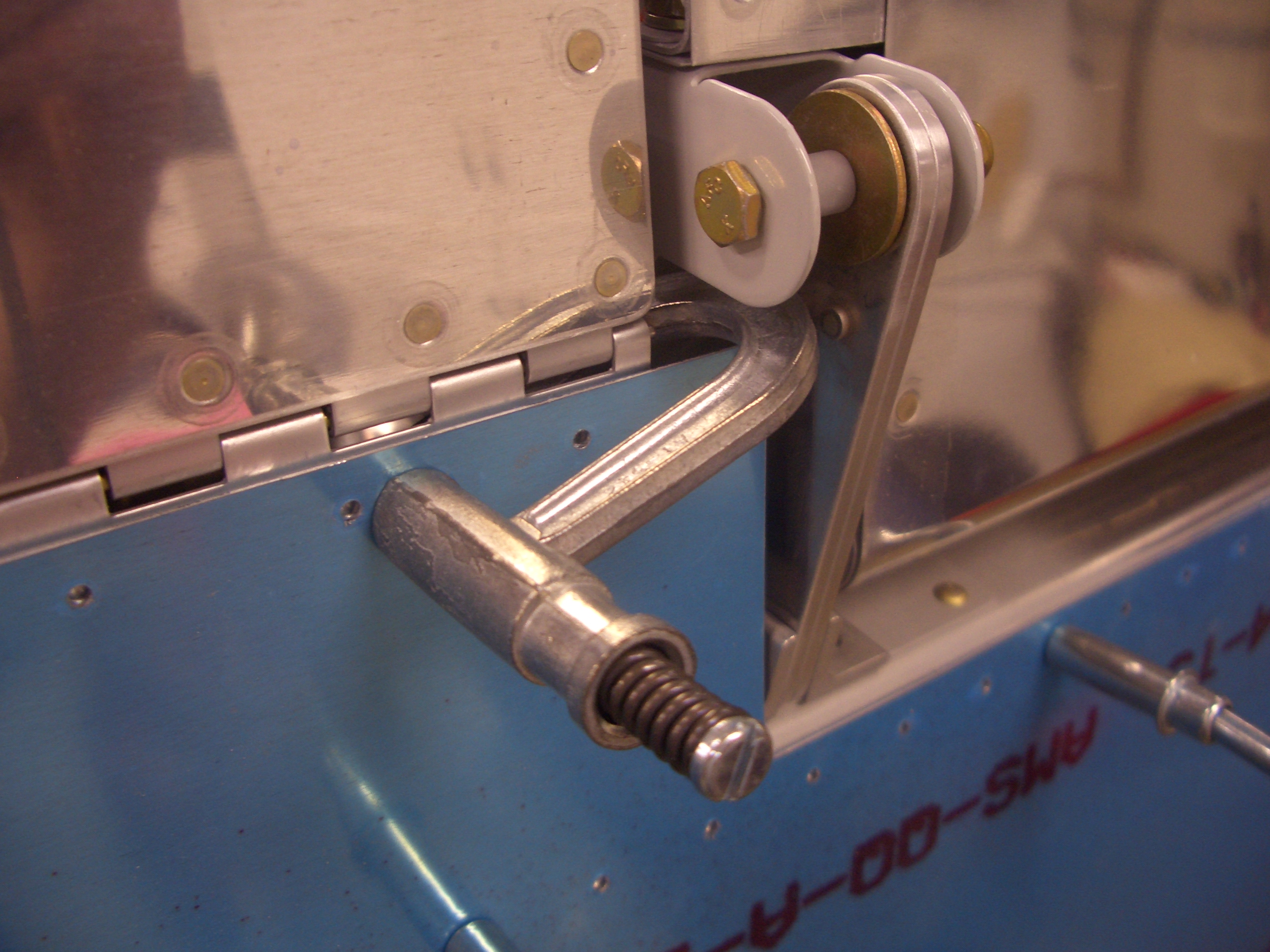
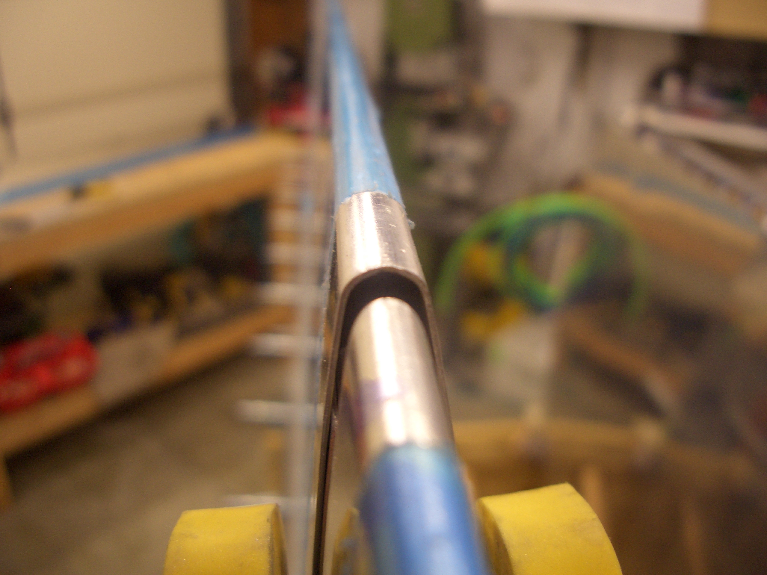
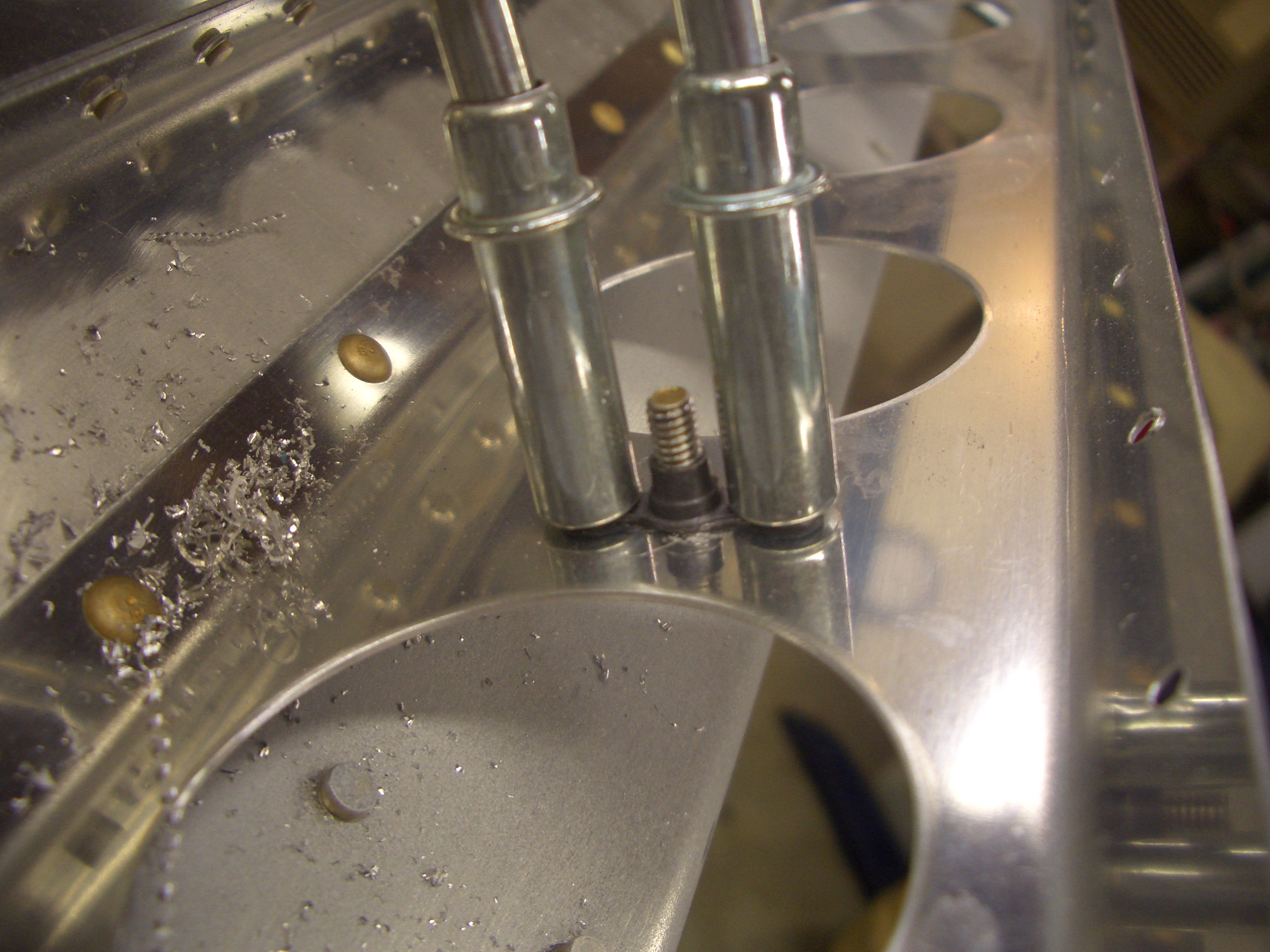
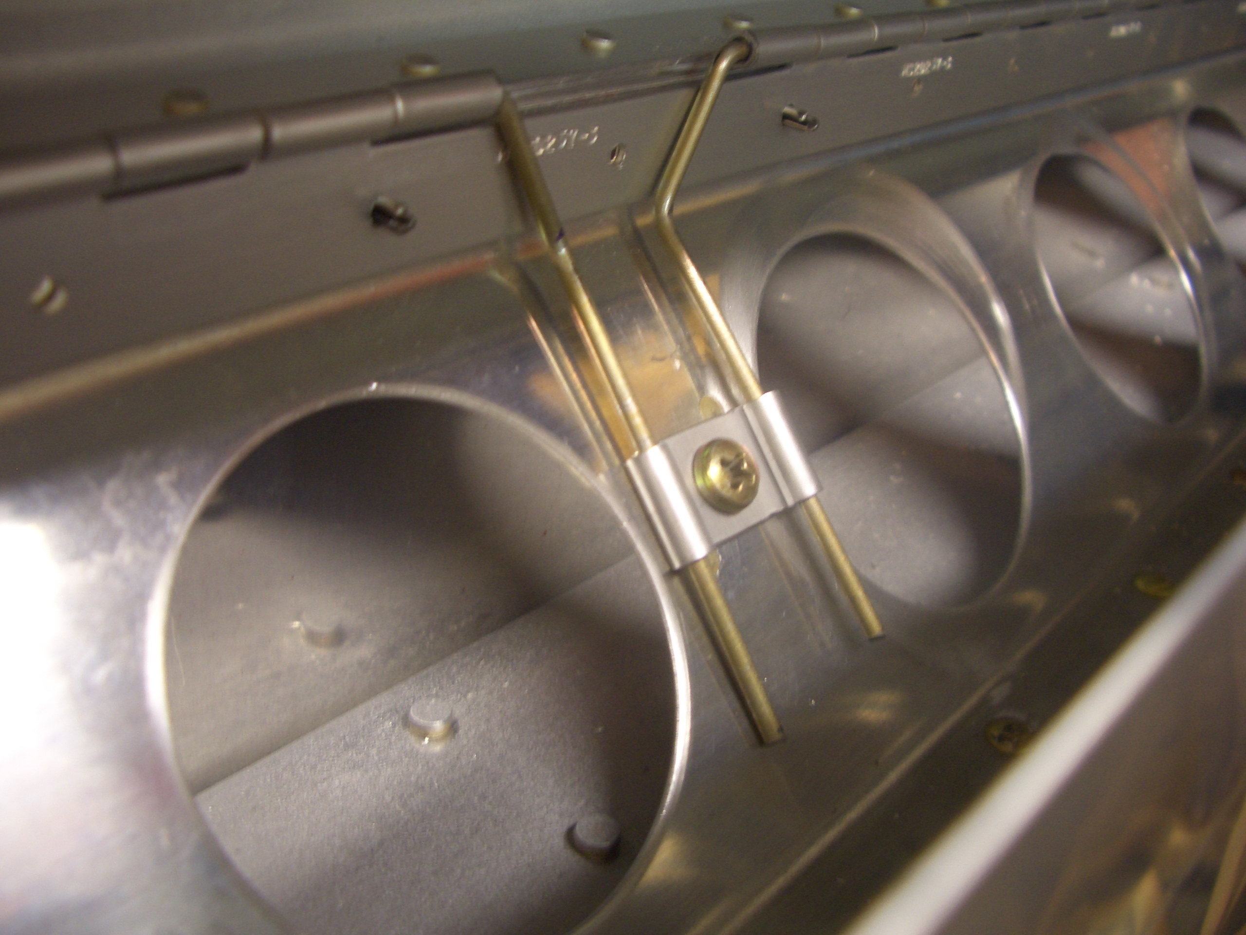
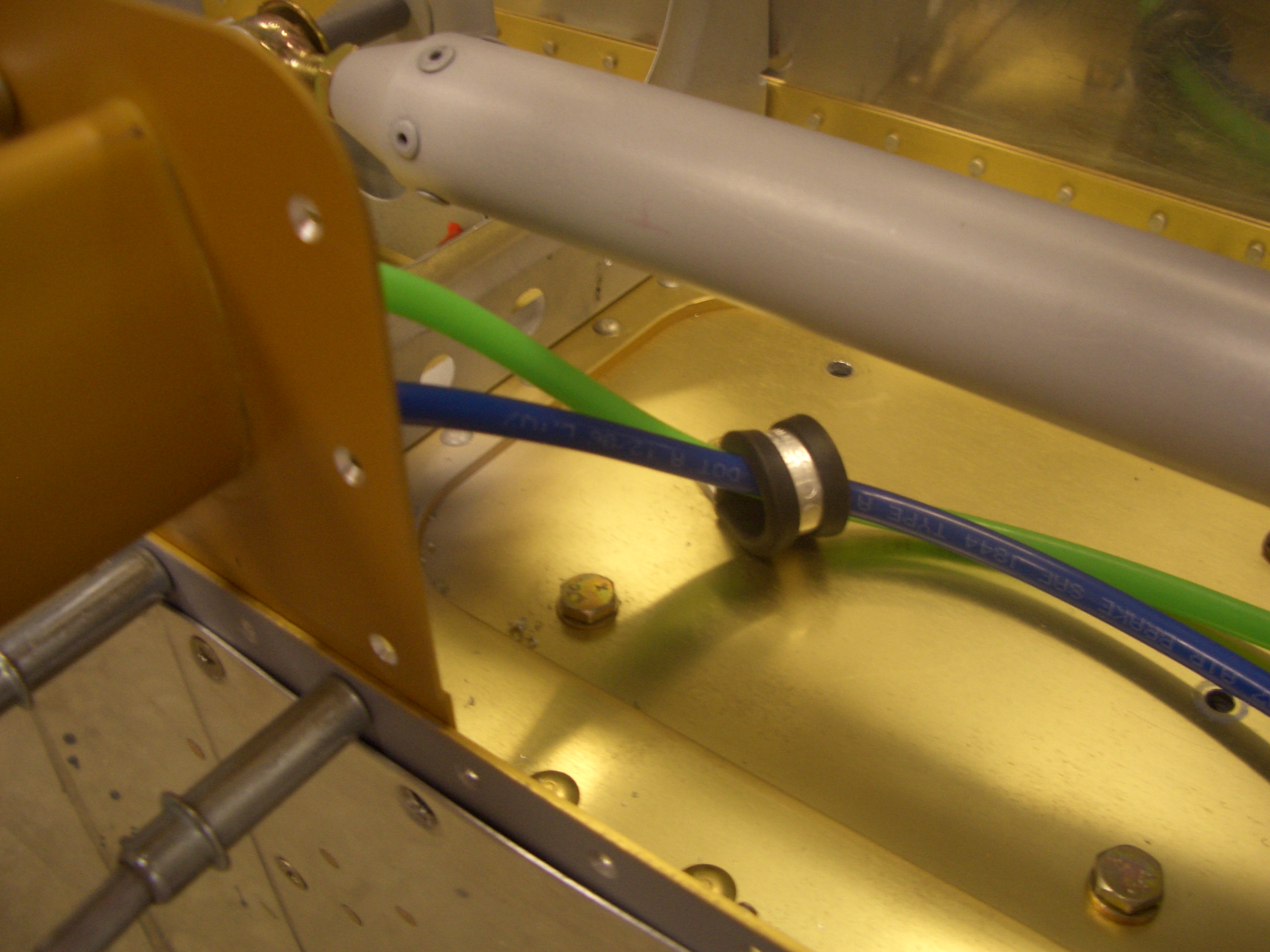
Here is a closeup of how the pushrod comes through the rear spar.  It’s clear now why the hole is oddly shaped as the pushrod traces a curved arc as the aileron is swung through full travel.  I verified with the digital level that the aileron can exceed the maximum allowable up/down travel.  I still need to fabricate the aileron stop that will limit the travel to the recommended amount.

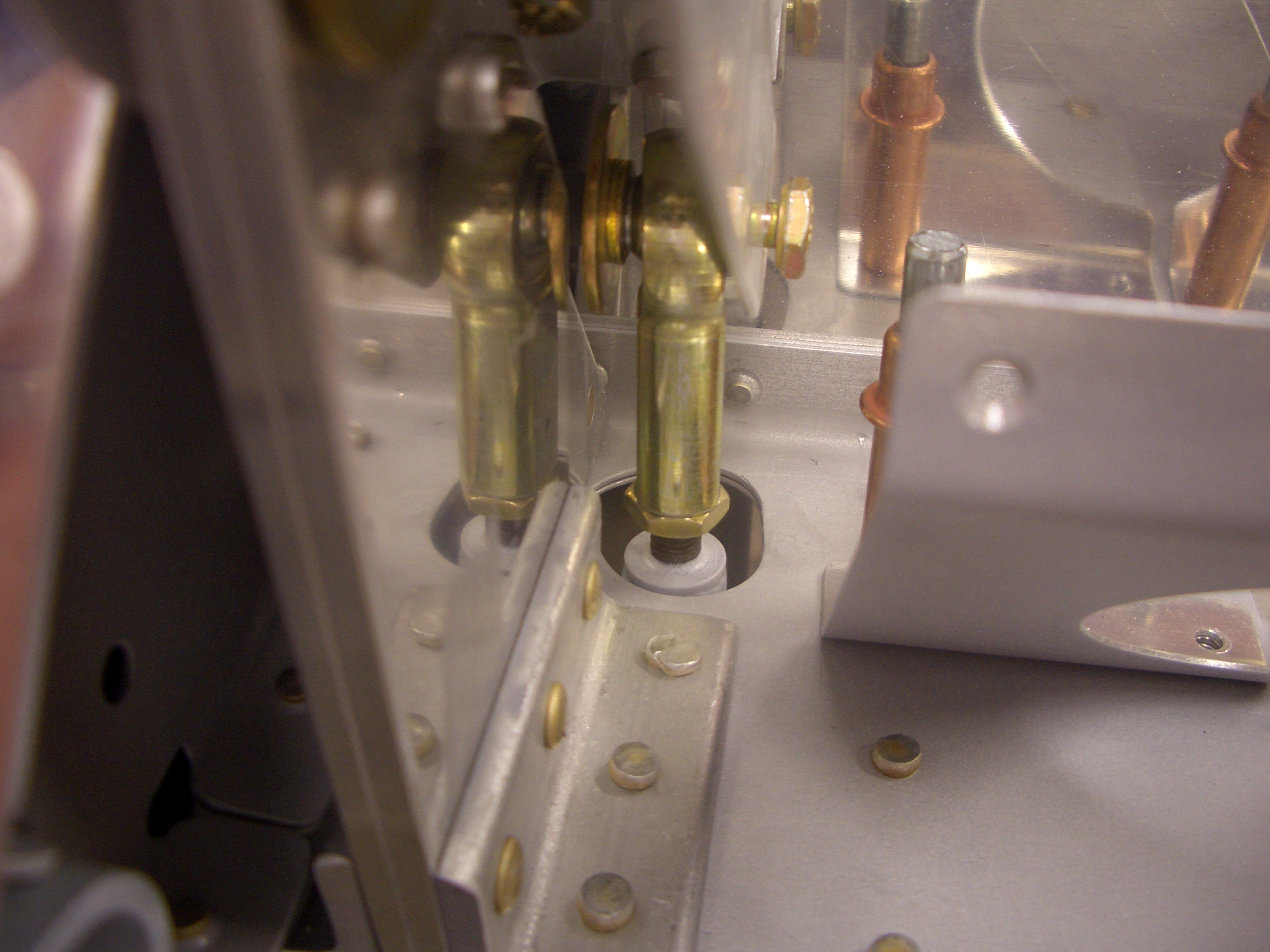
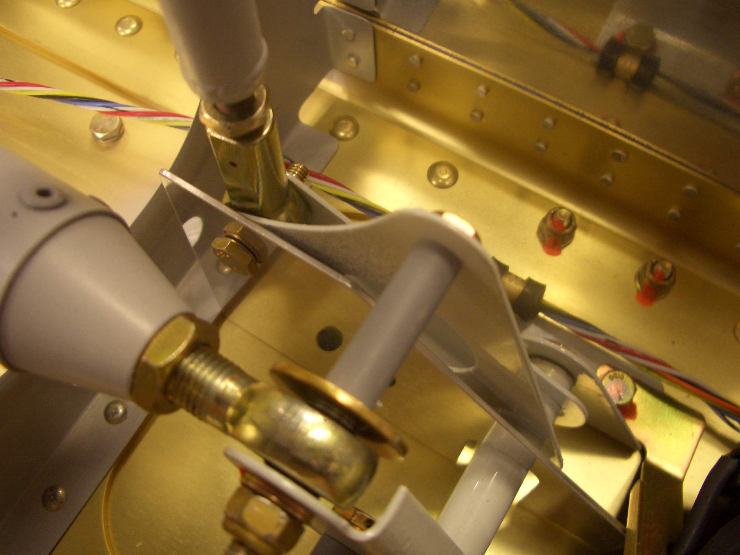
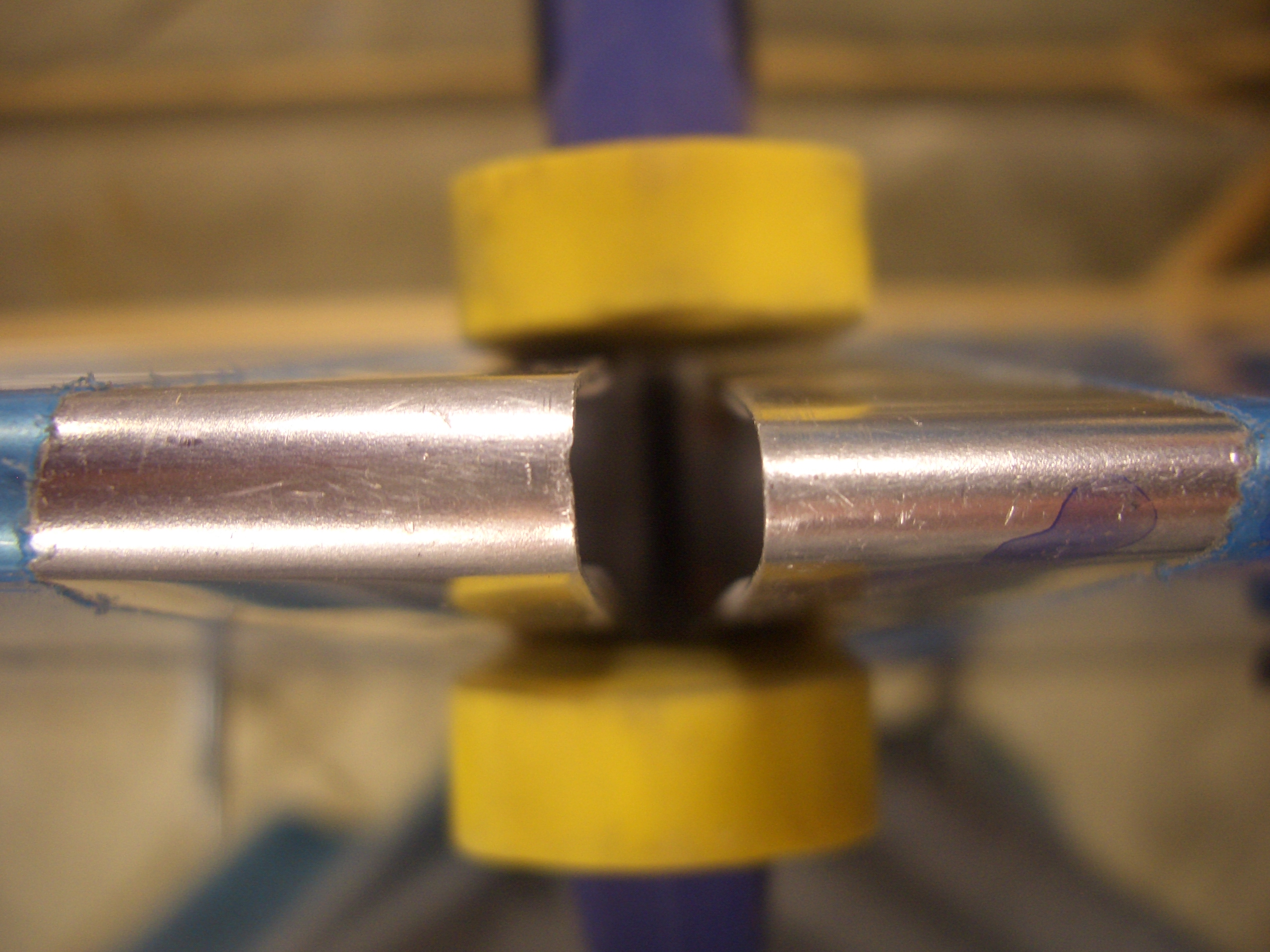
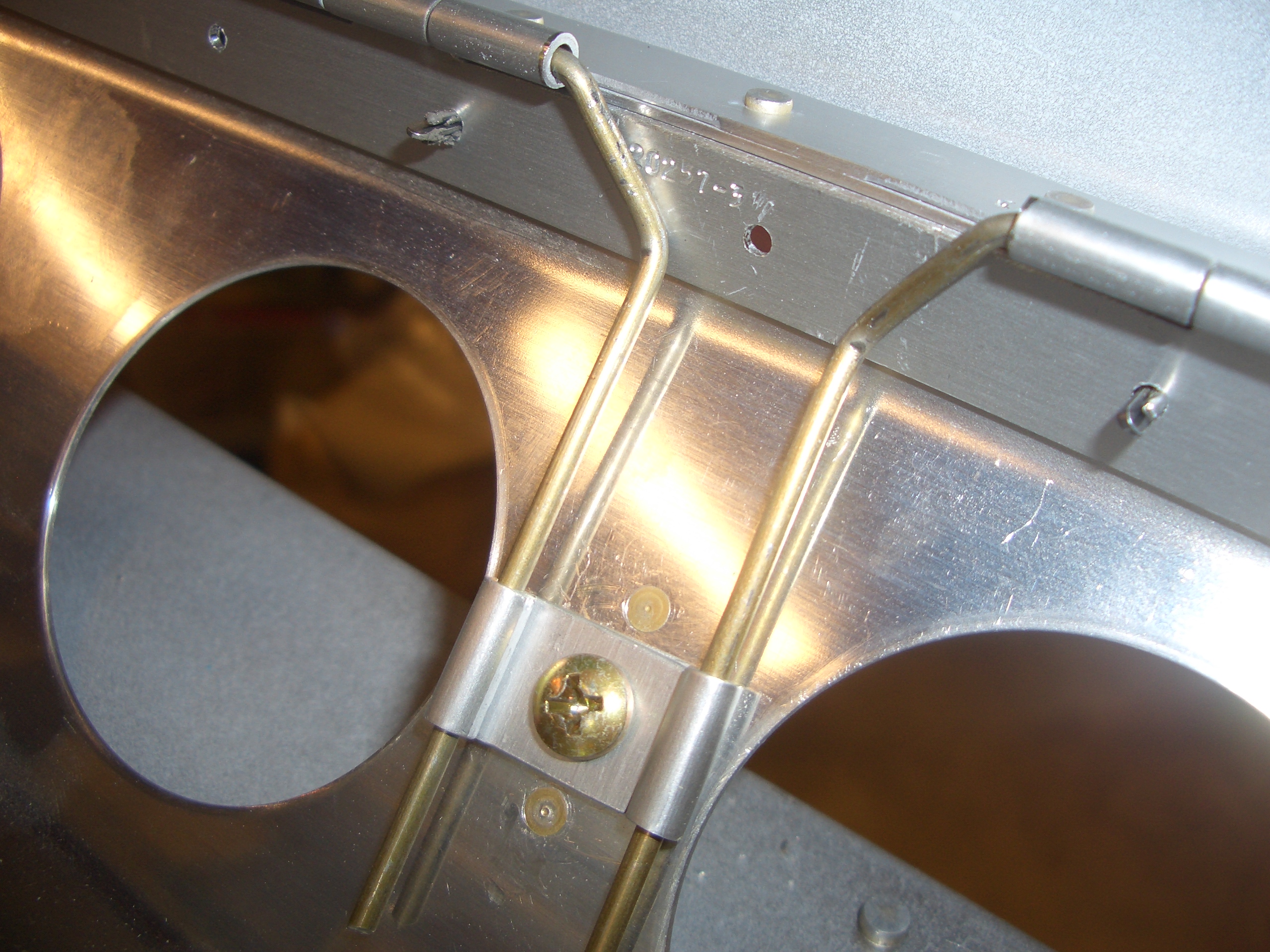
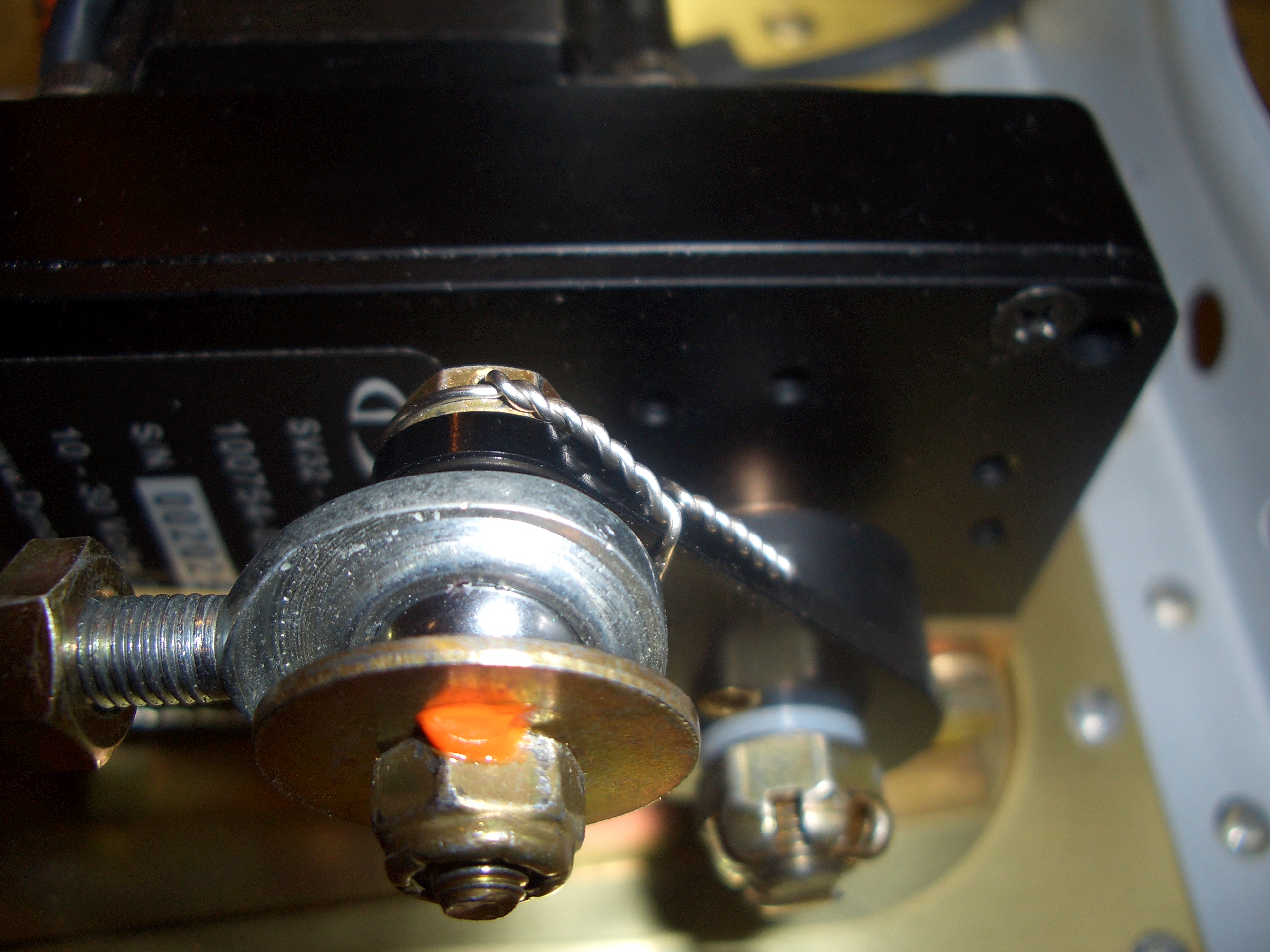
Here is how the pushrod attaches to the bellcrank.  Again, nothing is torqued down until I know that it’s on for good.

Riveted Flap Braces, Installed Other Aileron, Safety Wired Autopilot Servo

After dropping the kids off the morning, I stopped back by the house and riveted on the flap braces.  I’m definitely getting the hang of riveting with the gun solo.  I slightly overdrove a couple of rivets (though not badly enough to drill out), but virtually all were perfect.

After work tonight, my wife was hosting a Bunco party at our house, so I was on kid duty.  After they went to bed, I had a little time before the ladies left, so I snuck out to the garage and mounted the other aileron.

I also safety wired the autopilot roll servo’s mounting bolts.  I’m still getting the hang of safety wiring.  It’s tricky to estimate how much extra wire to leave before twisting since the wire segment shortens as you twist it.  It only took two tries to get this properly secured.

Started Rigging Ailerons, Aligning Flaps

The first step in rigging the ailerons is to place the aileron alignment bracket over the bellcrank with a bolt through it and the rear aileron push tube’s end bearing.

Next is to adjust the length of the rear pushrod until the trailing edge of the aileron lines up with two tooling holes in the main wing rib.  I placed a couple of AN3 bolts through these holes and then put the straight edge against both sides of the bolts until the trailing edge was centered between them.  I loosened the rear aileron push tube end bearings evenly so that I will have the same amount of threads showing at each end.

Next up, I clecoed on the bottom skins and put the right flap in place.  I spent awhile adjusting the position of the end clamps to get the trailing edges in perfect alignment.

I think I said it before, but these clamps have come in super handy.  I would highly recommend getting some if you’re building.

As I was aligning the trailing edges, I noticed something funny.  The trailing edge radiuses of the flaps and ailerons are not the same.  Here is one shot looking along the edge.  The aileron is the lower trailing edge with the smaller radius and the flap is the upper trailing edge with the larger radius.

Here is a shot looking down on the trailing edges.  The problem is that with the trailing edges aligned front to back, the skin surfaces no longer align.  If I make the top skin surfaces flush, then the flap skin on the bottom of the wing will be proud of the aileron bottom skin.

I don’t think I can just squeeze the flap trailing edge either since the flap skins nicely follow the angle defined by the end ribs.  If I squeeze the trailing edge, the skin will have to bend inward as it crosses the trailing edge of the end ribs.  I’m going to see if anyone on vansairforce.net has any ideas.

Update: It turns out that the scale drawings on the flap and aileron plan pages clearly show that the flaps and ailerons have different trailing edge radii, so I’m not going to do anything about this.

Drilled Right Flap

After triple checking all of the measurements, I drilled the flap hinge to the wing.  I ended up using the P3 hinge that ships with the kit, and I’m well over the minimum 3/16″ edge clearance for AD3 rivets (I’m less than 1/32″ beyond the recommended 1/4″ edge clearance).

Here’s a shot of the whole wing.  The control surfaces add considerable area to the wings.

Drilled Left Flap

I got up this morning and drilled the left flap before work.  This side didn’t end up quite as good as the right side (the flap trailing edge ended up about 1/64″ below the aileron trailing edge as it’s standing vertically like this).  I looked around at a bunch of builders websites and this is apparently a really common problem and 1/64″ is actually better than most.  I don’t think I’m going to replace the hinge since it could easily end up worse.  I may be able to tweak a few things to make it just about disappear when finally riveted together.

Van’s offers a couple of suggestions for securing the flap hinge pin.  The first is to drill a hole in the inboard aileron bracket that’s intentionally slightly out of alignment with the hinge pin.  The hinge pin is then inserted through this hole and the misalignment prevents the pin from sliding back out.  The other suggestion (which most builders including me go with) is to remove several of the hinge loops near the center of the hinge and then secure the hinge pins  against the flap brace.  Here I’ve removed one loop on the flap side and two on the wing side.  You can also see here how close the rivet holes ended up to my line drawn at 1/4″ from the lower edge.

I drilled the flap brace for the #8 nutplate and riveted it on with a couple of oops rivets.

Here you can see how the hinge pins are secured.  The bends in the hinge pins prevent the pins from migrating toward the ends of the flaps and interfering with either the ailerons or the fuselage.  The clip (which I made by cutting a couple of loops off of some extra hinge material) will keep the hinge pin from migrating inboard.  I’ll cut off the extra pin material that’s sticking out beyond the clip the next time I have the flap off of the wing.

Bottom Wing Skin Prep

Now that I’m feeling better, I got started prepping the bottom wing skins for riveting.  I deburred and dimpled two of the skins and installed the nutplates in three of the six cutouts.  After the wing skins, I only have a small punch list of items to complete before I’m ready to rivet the bottom skins on:

  • Put remaining tank bolts in place and torque all tank bolts.
  • Put proseal around conduit where it penetrates each rib to prevent vibration from cutting through them.
  • Reroute roll servo wire through smaller rubber grommet so that the wire can’t move as much.
  • Fix a couple of bent rib flanges inside the main spar flanges
  • Fabricate a support angle to tie the pitot tube mount to the adjacent rib to keep the skin from having to carry any flexing load.

Safety Wired Final Bolts on Roll Servo

I safety wired the remaining two bolts on the autopilot roll servo.  These are the bolts at either end of the short pushrod from the servo to the aileron bellcrank.  These nuts as well as the remaining nuts in the aileron control linkage have been final torqued and torque sealed (orange lacquer).  This is the bolt on the servo end of the pushrod.

This is the bolt at the bellcrank end of the pushrod.  I drilled a tiny #50 hole in the flange of the bellcrank to safety wire the bolt to.

Pitot Tube Mount Support

I fabricated a short piece of angle to tie the pitot tube mount to the adjacent wing rib.  Positioning this required putting the pitot mount and bottom wing skin in place so that the piece of angle could be clamped to the rib.  After removing the mount and bottom skin, the angle could be drilled to the rib.

Below the large push tube, you can see one of my experiments in keeping the pitot and AOA tubing away from the push tube.  I’m not going with this arrangement, but I’ll post something in a few days about how I’m handling this.

Here it is with the mount back in place.  This bit of angle adds considerable rigidity to the mount.

Pitot/AOA Tube Routing

I used some self-fusing silicone tape to keep the two fittings on the pitot tube from rubbing against each other or the inside of the pitot tube mount.

I also used a MS21919-DG10 clamp to route the tubes towards the spar so that they don’t interfere with the aileron push tube.  The DG10 has enough free play that I can slide the tubing through it if I ever need to take the pitot out.  I’ll have quick disconnects in the wing roots that I can disconnect to create the slack to do this.