Moving Day!

Today was moving day.  My dad, brother and a bunch of friends came over to help me move everything.  We ran one load down to the airport with almost everything but the fuselage then came back for that.  The liftgate was not wide enough to get the gear completely on, so we laid a piece of plywood over it to give us a little margin of error.

Here’s the fuselage all strapped down for the ride.  It worked well and arrived unscathed.

Here’s some of the moving crew.  Thanks to all of you for your help!

Several of the guys (including one local pilot who stopped by when he saw the moving truck) stayed around until evening and we got both wings mounted (but not torqued) and the horizontal stabilizer installed.  Thanks guys!

Unfortunately, when hammering in the bolts on the left side, I ended up bending the gusset that ties the spar to the lower longeron.  It’s a fairly gentle bend, so I’m going to try and bend it back before ordering a replacement.  Fortunately, this part is fairly easy to remove.  It would be a serious pain to damage a part that is permanently installed or hard to access.

Update: On the advice of another builder who follows my site, I called Van’s about this and spoke with Joe Blank.  He said that as long as the piece wasn’t bent back and forth until it work hardened, it would be fine.  Although this is exactly what I expected them to say, it was good to have some further piece of mind.

Landing Lights and Tool Modification

I fabricated the light side of the wiring harness today.

I wrapped the power board with some foam to protect it from vibration and stuffed it inside the light.  I stopped by the hangar later in the day to remove the canopy and tried out the lights.  Unfortunately, the right landing light was intermittent.  I ended up tracing the problem to a poor solder connection on one of the LEDs, so I re-soldered it.

With the right lens almost trimmed to final size, I decided to drill it to the wingtip so that I could install it in the same place every time during final trimming.

Torquing the jam nuts on the rod ends used as hinges on the elevators and rudder require a special tool.  I picked up a set of these offset wrenches from Harbor Freight yesterday and modified it to fit around the rod end.  I cut a slot in the end and reduced the thickness quite a bit.  I’ll try this out tomorrow and see how well it works.

Airplane Inspection Party

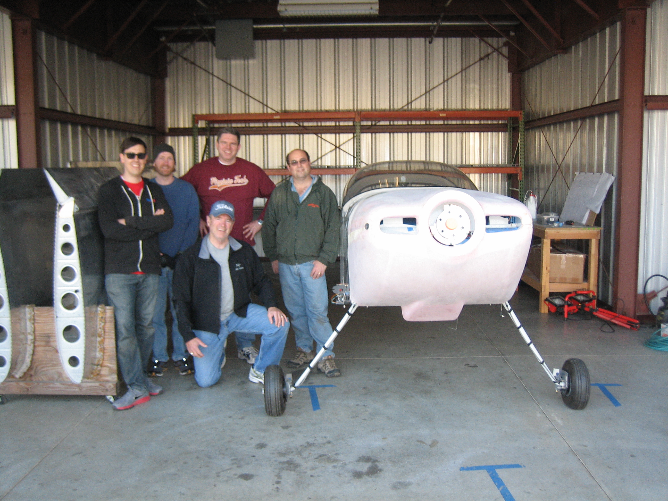
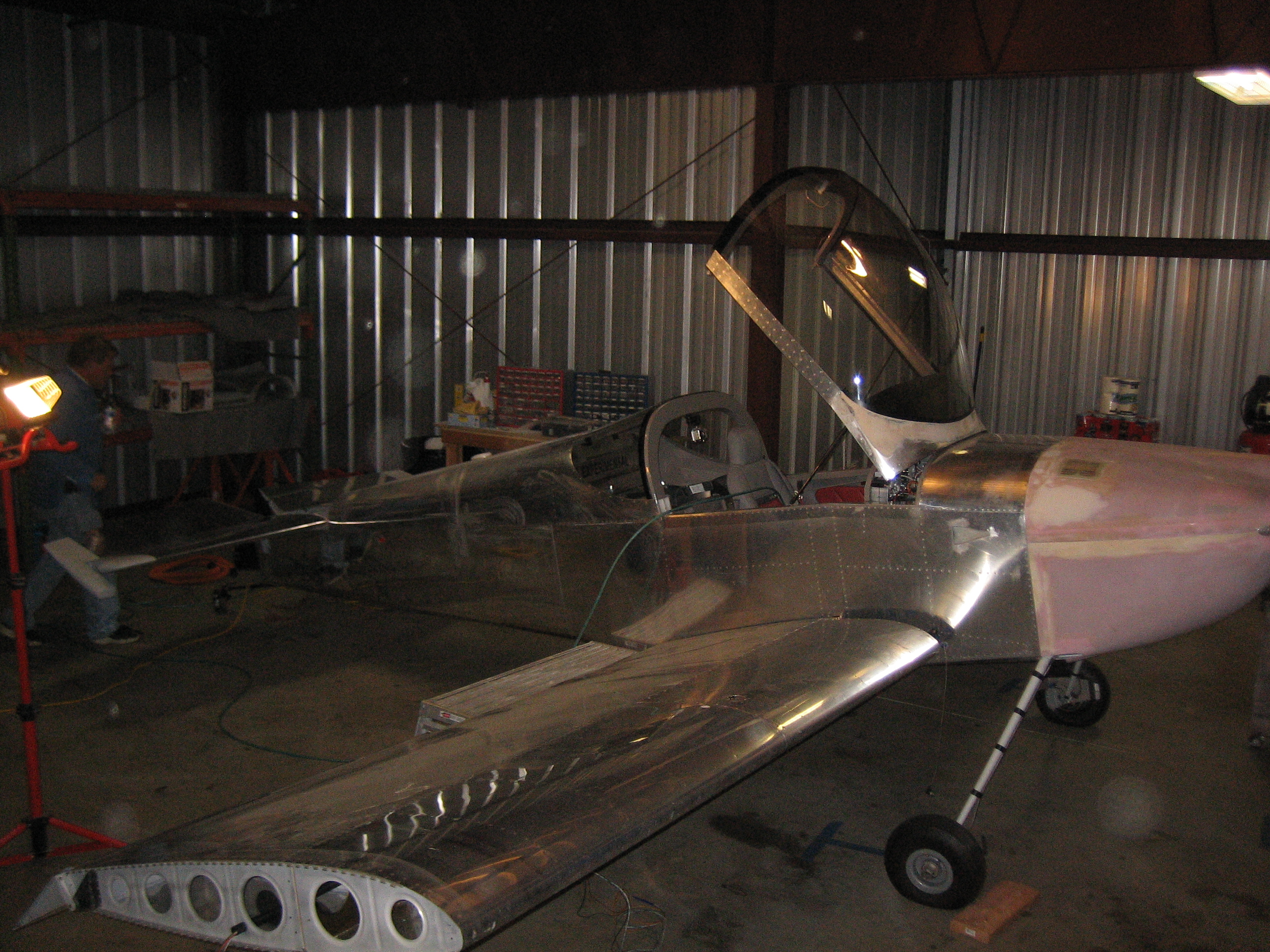
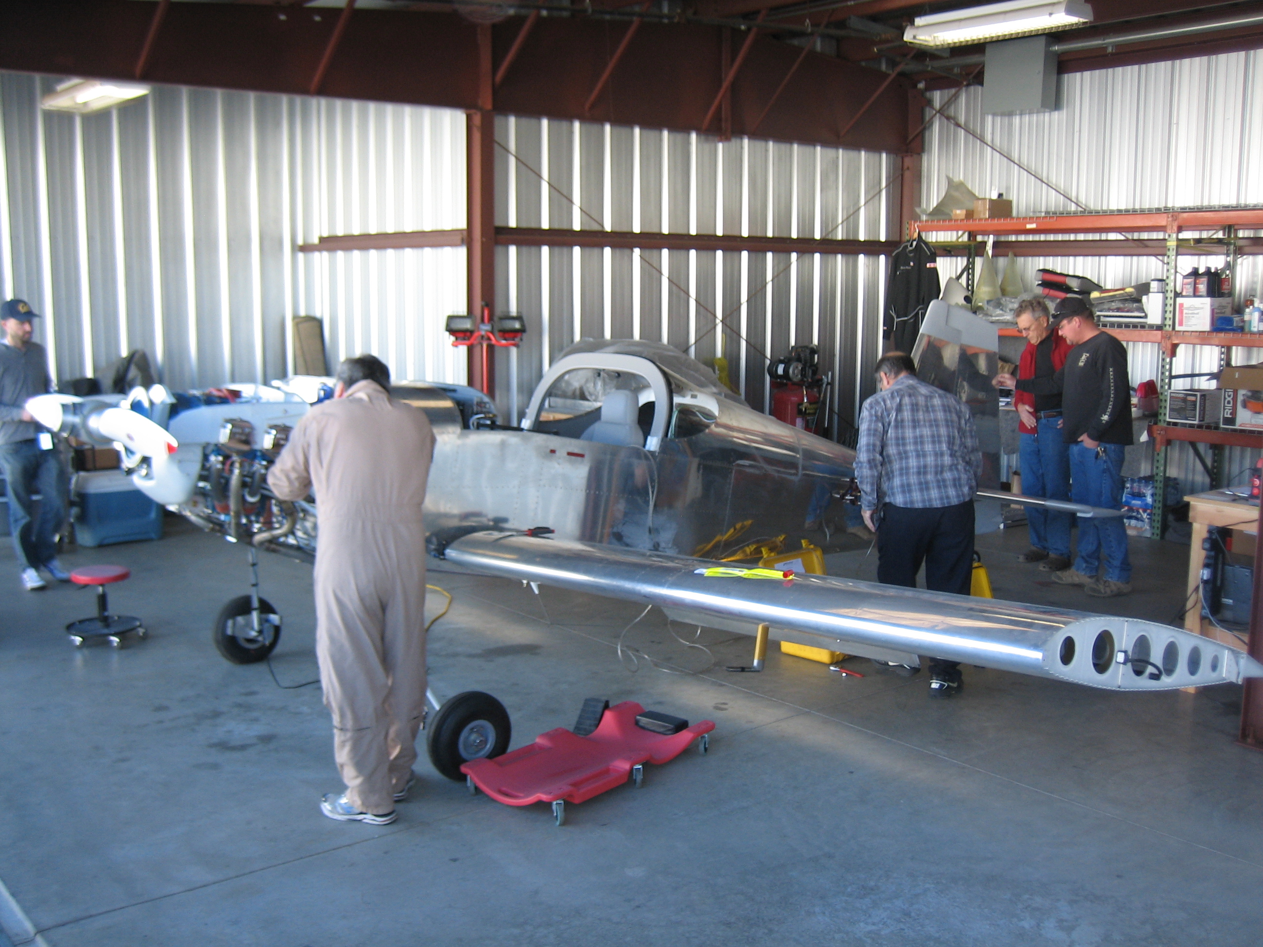
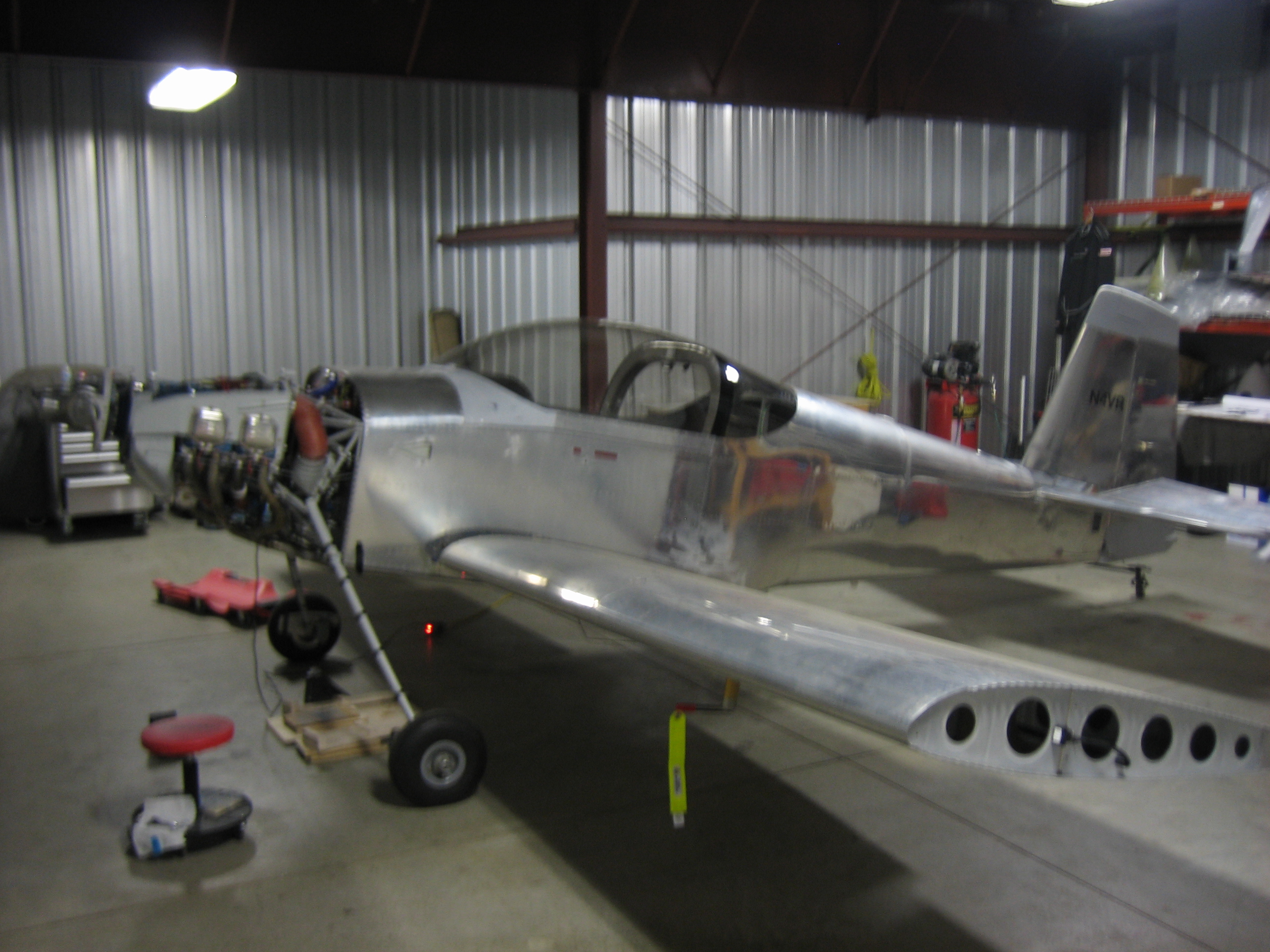
I had my airplane inspection party today.  I invited RV builders from all over the region to come give my plane a good once over before scheduling time with the DAR.  I had a great turnout; roughly 40-50 pilots and builders stopped by over the course of the day.  Overall, the inspection went very well.  Nothing major was found, but there were a number of small items people caught (some of which I knew about and some I didn’t).  I just want to give a huge thank you to everyone who stopped by.

The day started with my transponder certification and pitot/static check.  The transponder check passed with flying colors, but I had a leak in my pitot system.

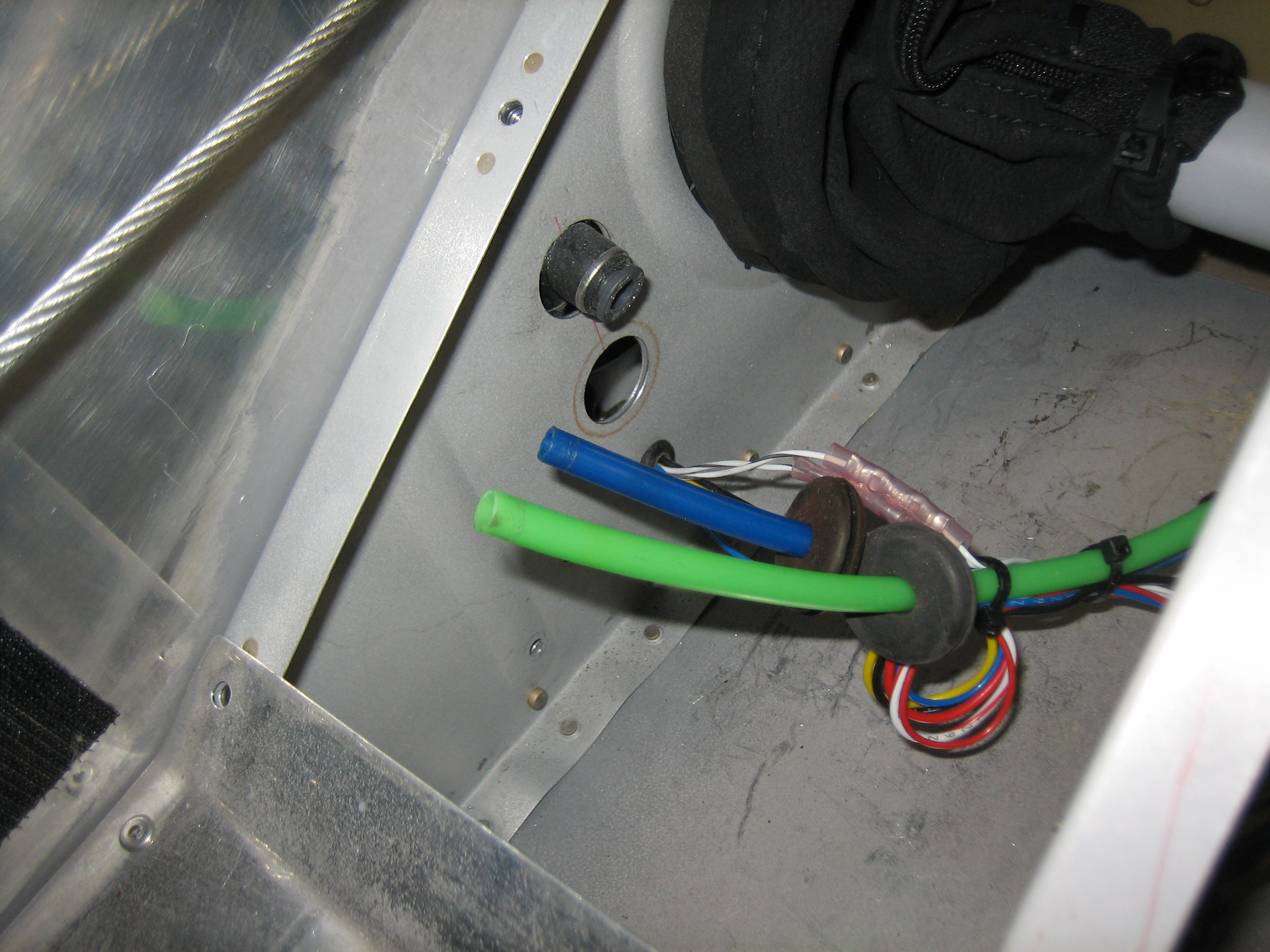
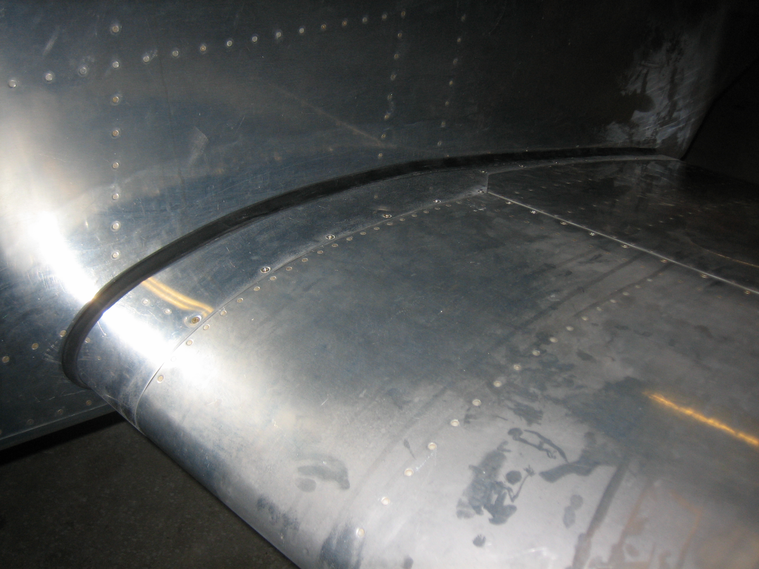
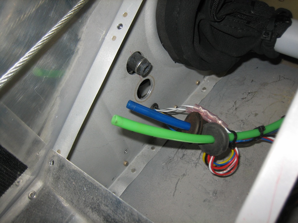
Unfortunately, the leak turned out to be in the wing root fittings where I didn’t quite get one of the pieces of tubing fully seated.  In the process of trying to seat it, the tubing popped out and I had essentially no access to get it back in.  This was really the wrong place to put these, so I’m probably going to have to pull new lines through the wings and make the connections under the pilot’s seat.  Do yourself a favor and avoid all wiring and tubing connections between the fuselage and wing on the RV-7; there is simply no room to work in there.

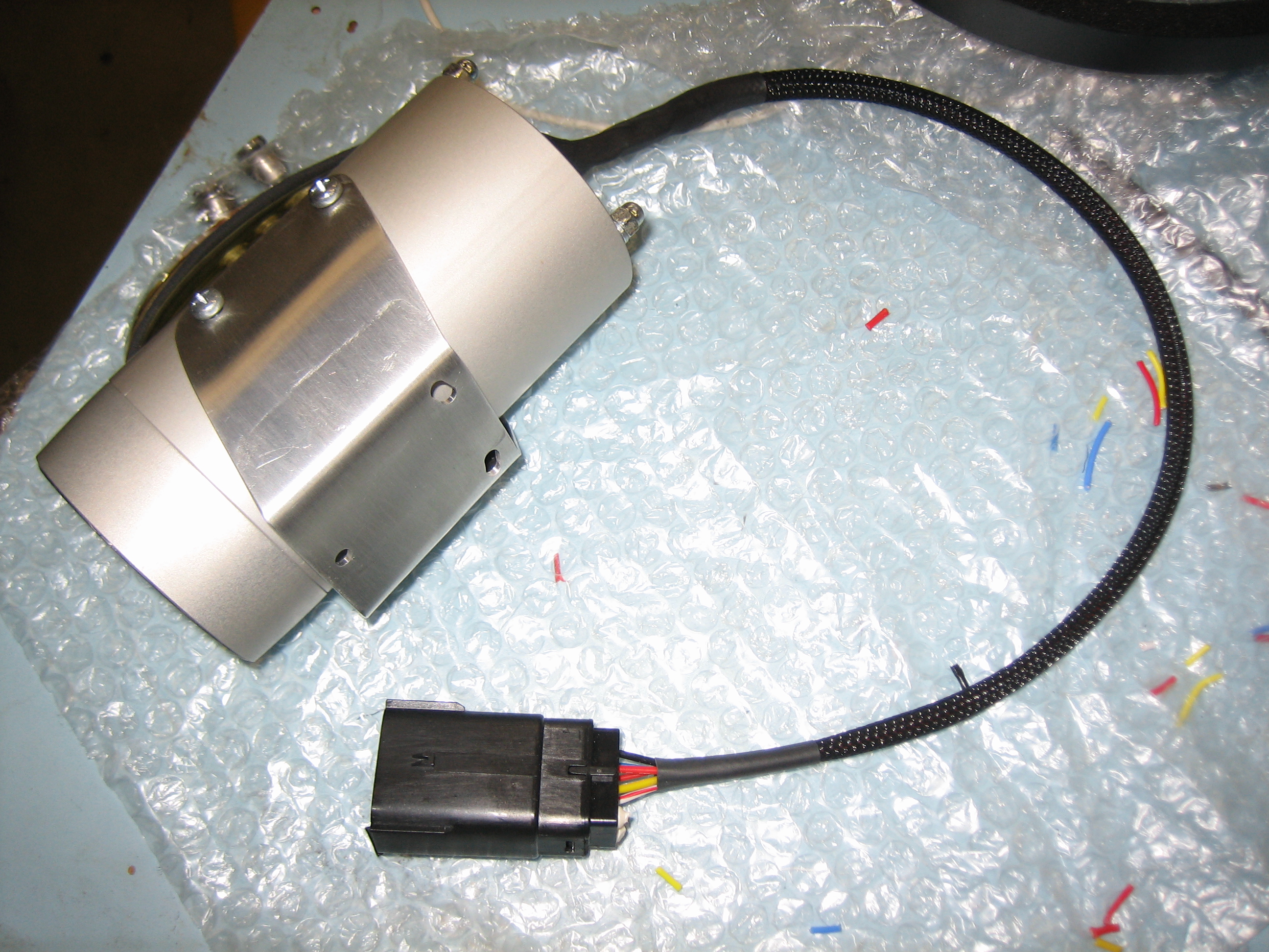
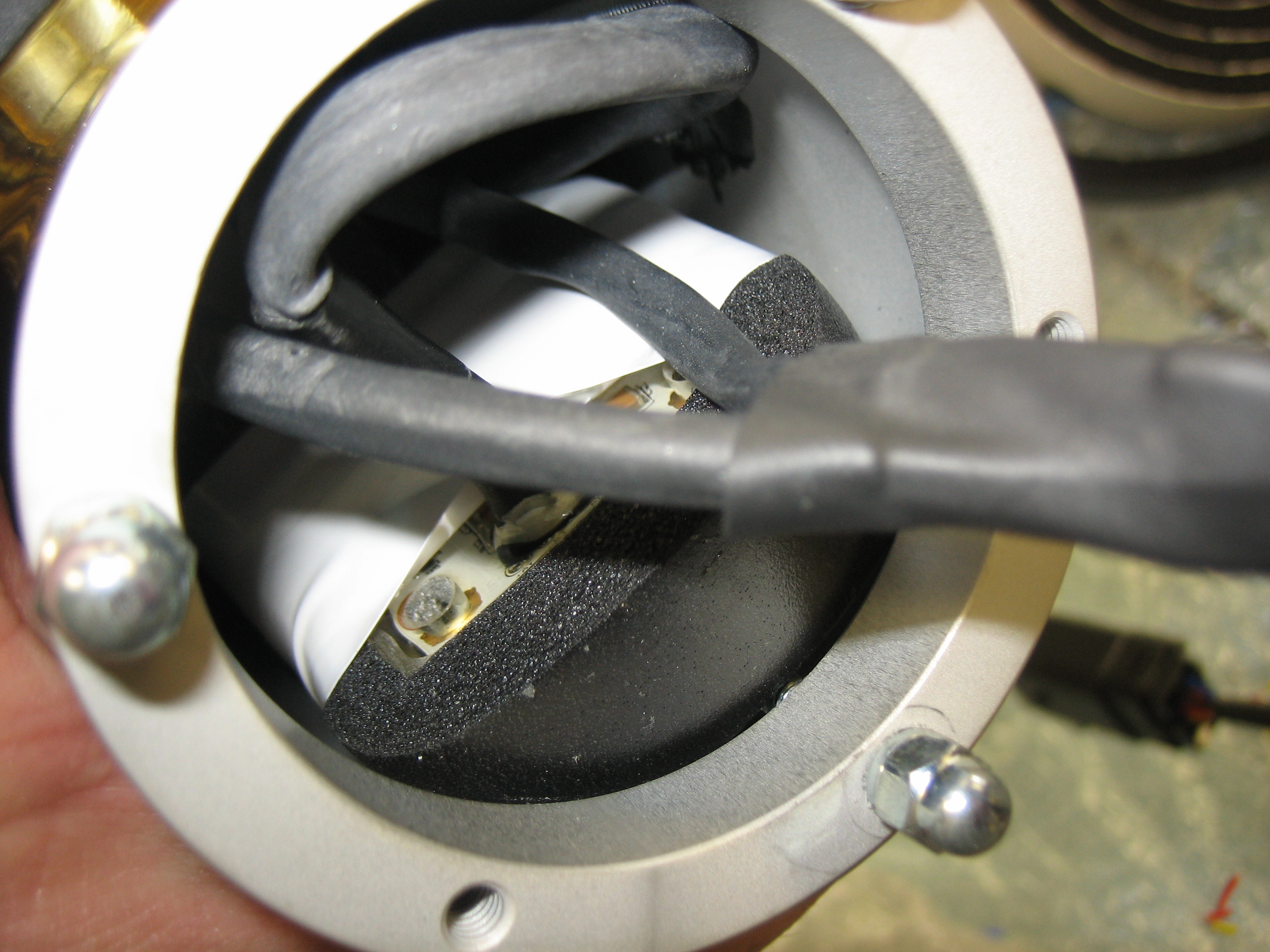
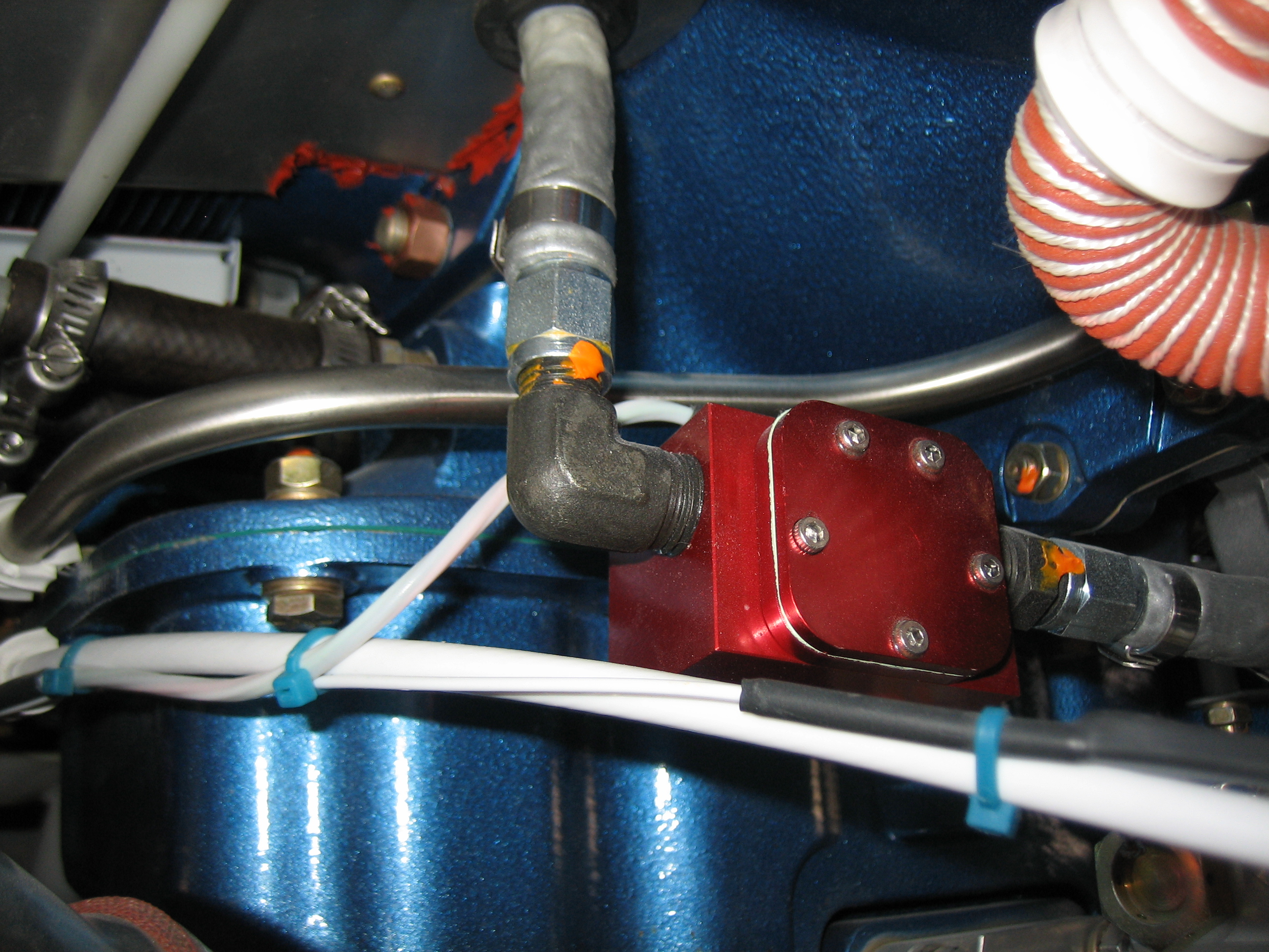
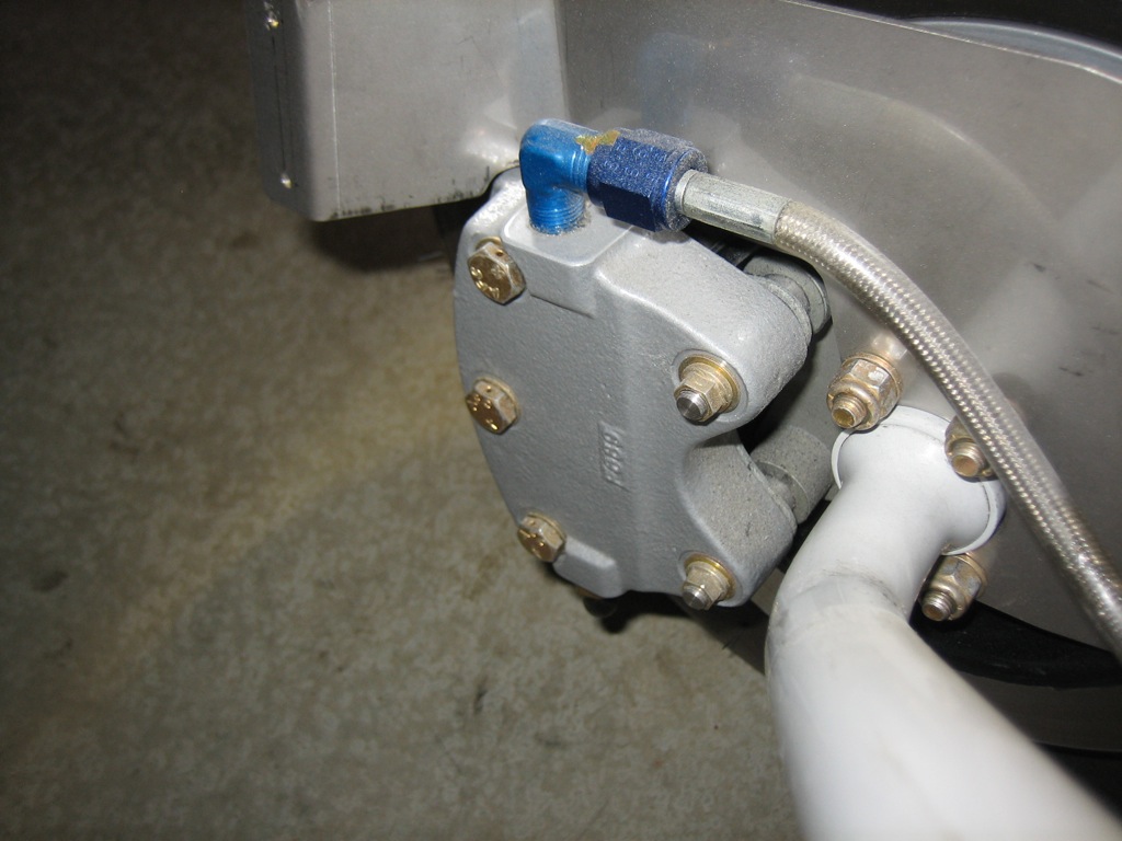
Now, on to the things that were caught during the inspection.  Let’s start with a few things that were squawked, but are not actually issues.  A couple of people questioned the mounting of my fuel flow transducer which is simply suspended from the fuel lines.  Apparently, there are two versions of the red cube.  The earlier one didn’t tolerate being rigidly mounted to the engine, but the later one could be mounted like this or to the sump.  When I purchased this, I called the manufacturer and they recommended this mounting approach.

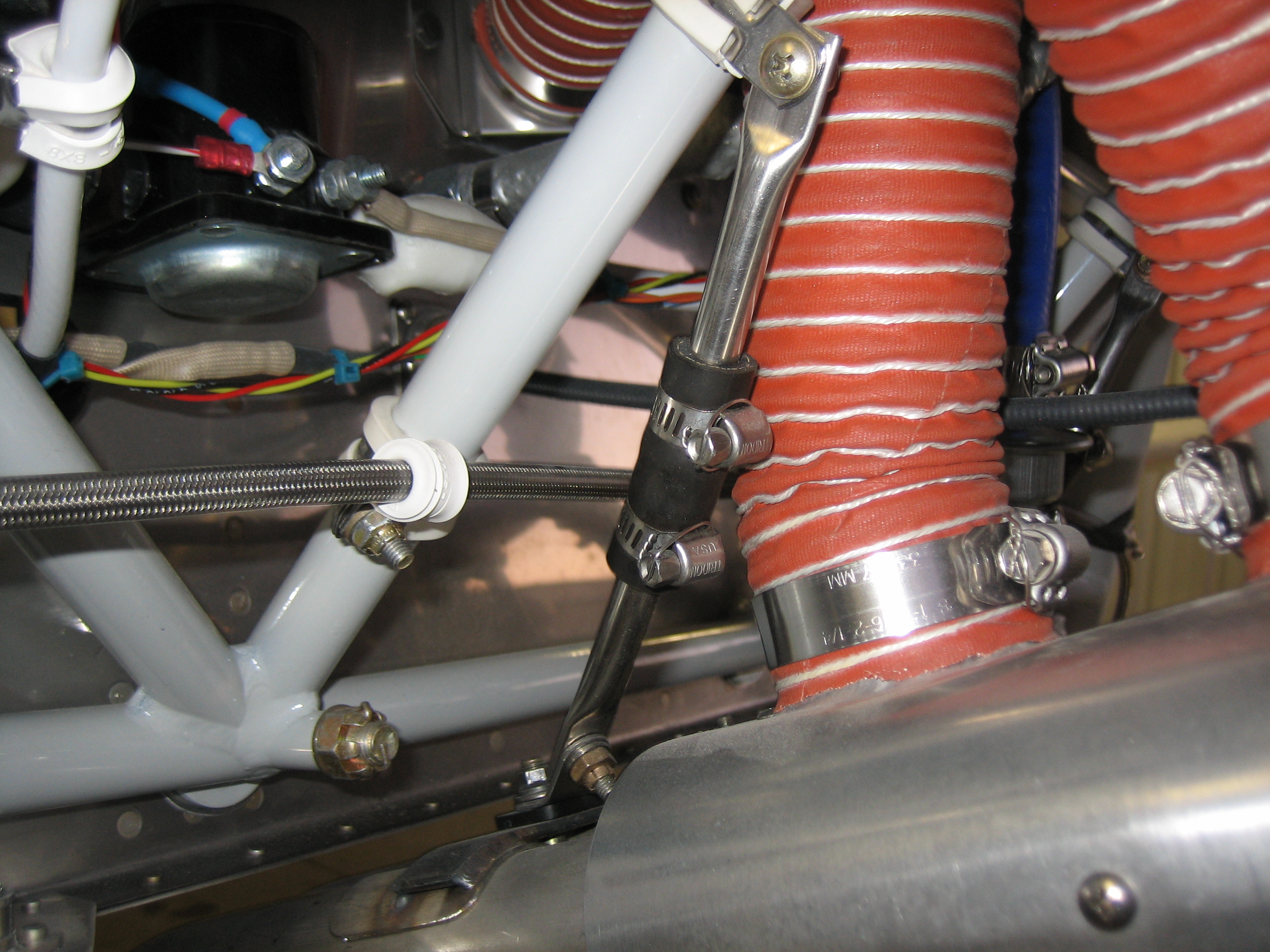
Another builder squawked that there was not enough rubber material on the exhaust hangers which would not allow sufficient movement in the exhaust pipe.  Larry Vetterman specifies that the stainless steel tubes only be separated by 1/4″ inside the rubber tubing, so this is installed as the manufacturer recommends.

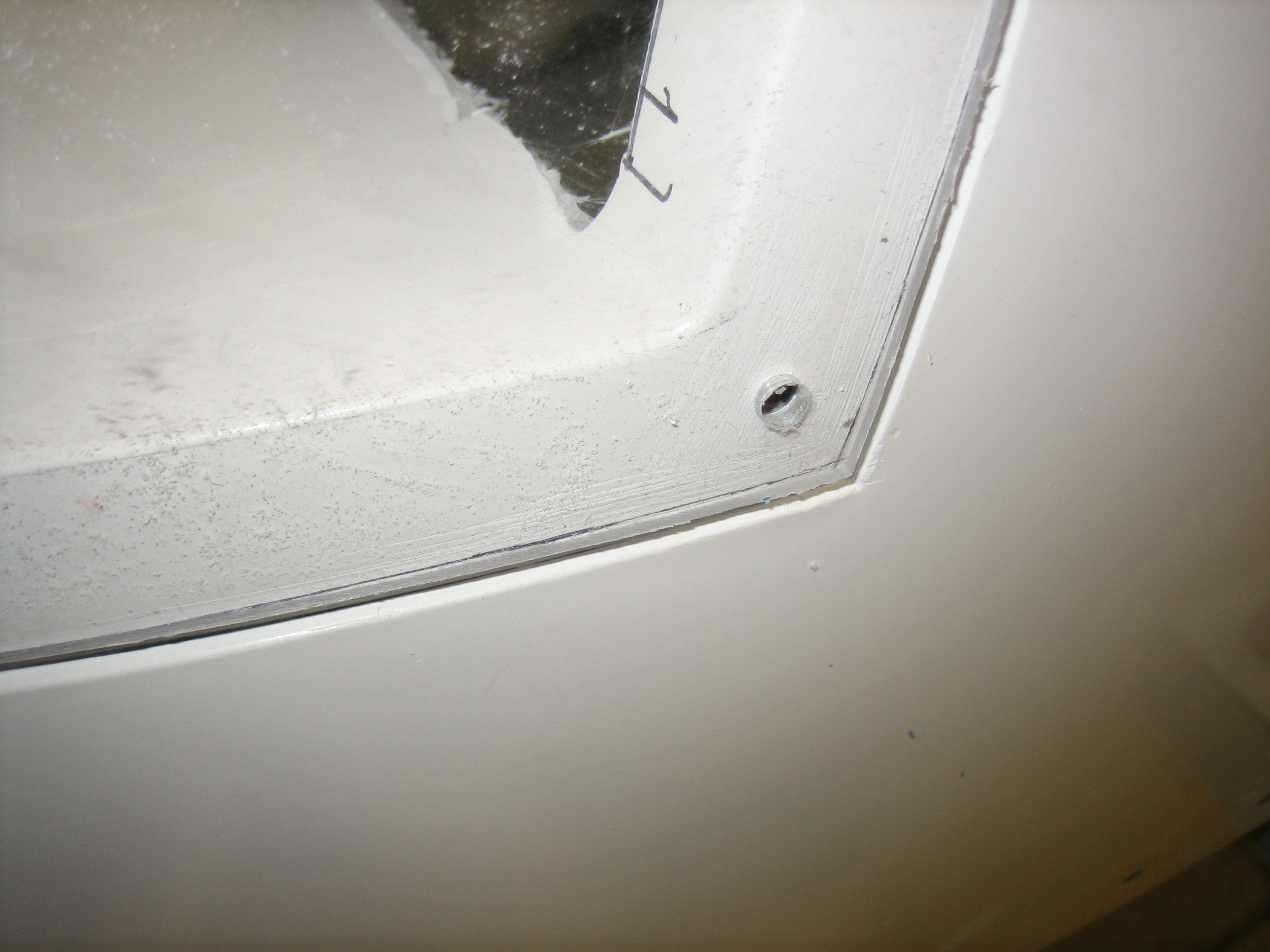
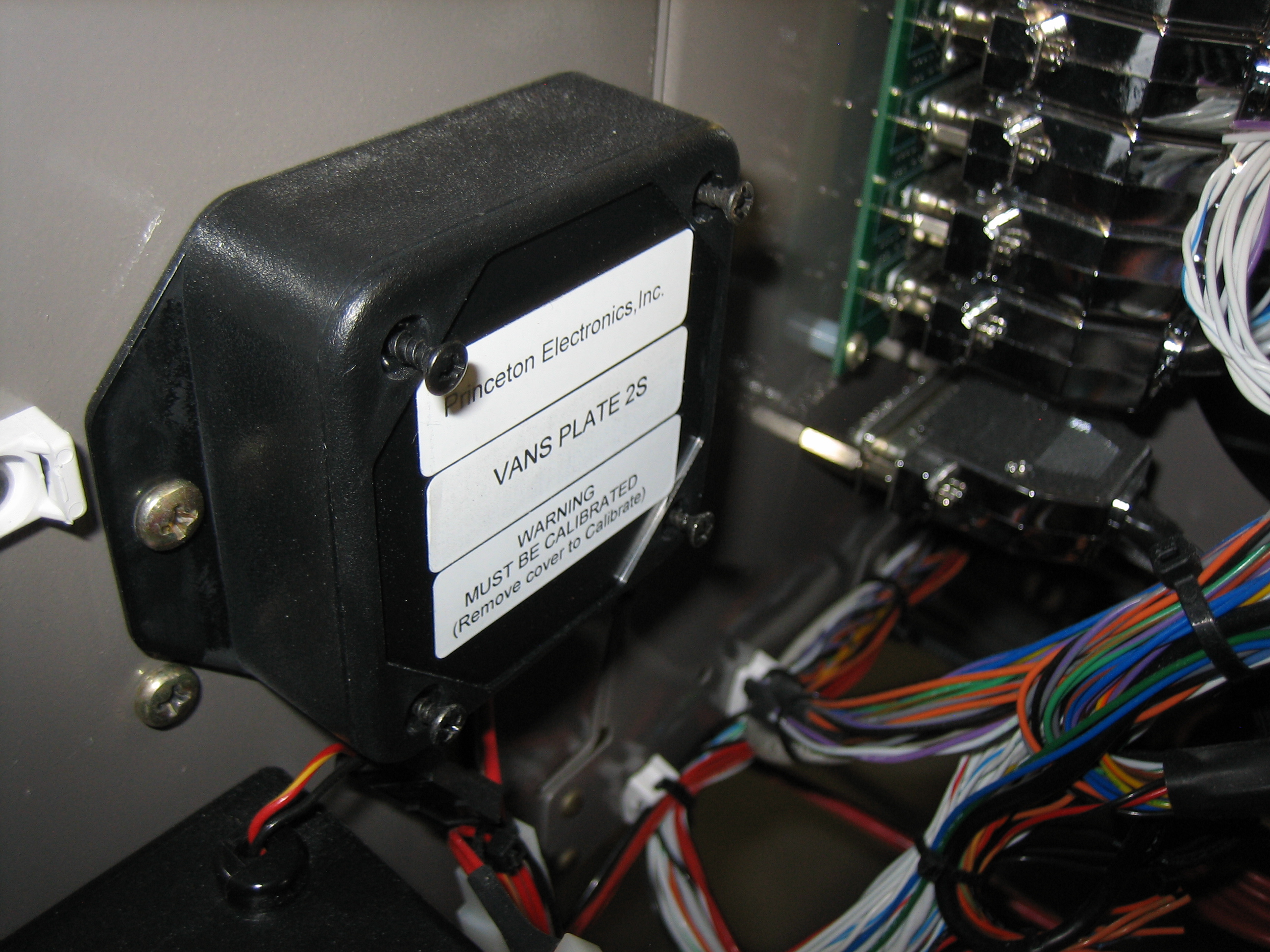
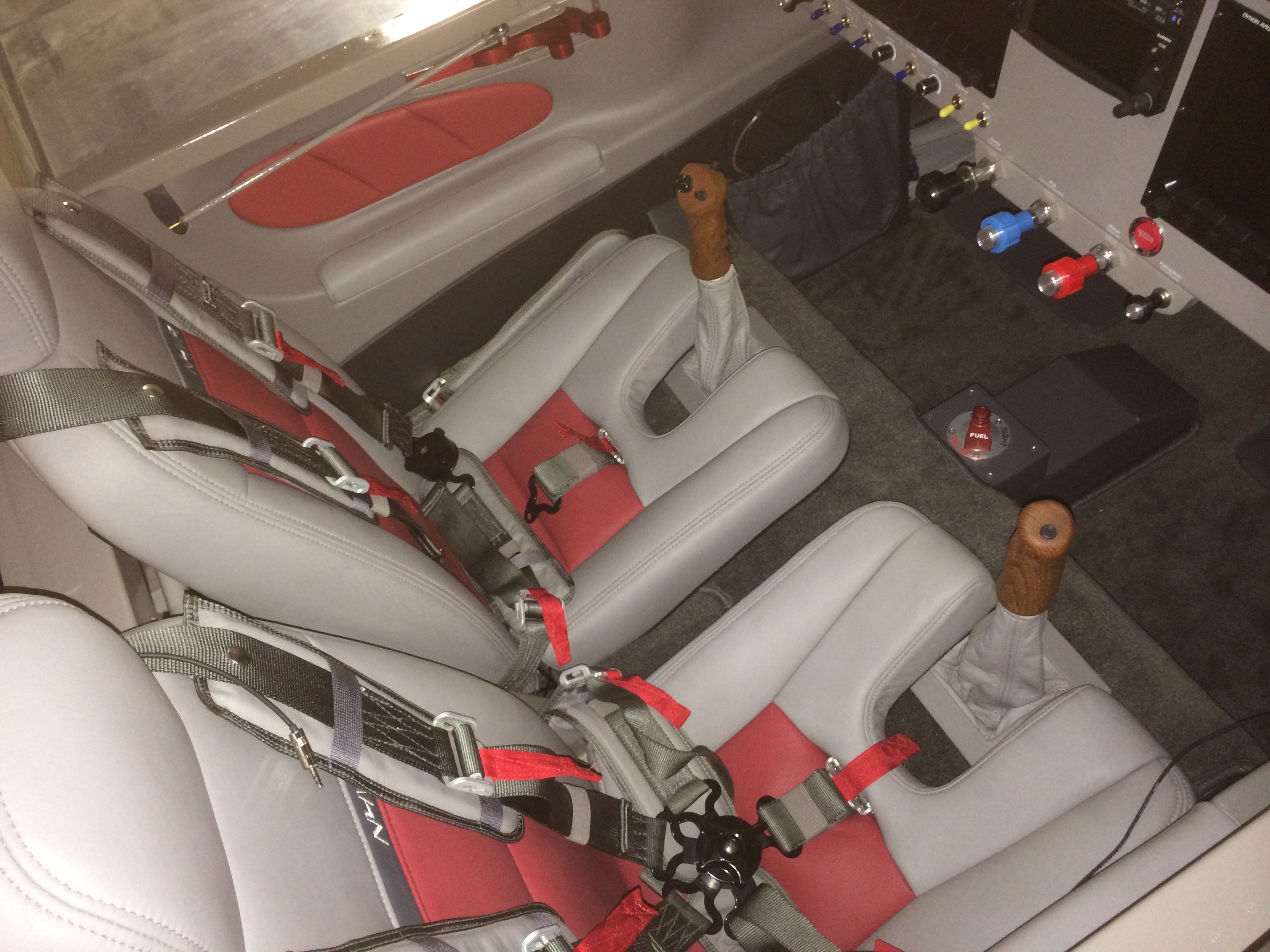
Next, let’s move on to some things that are actually issues, but I knew about.  Someone mentioned that the screws weren’t fully installed in the fuel senders.  This is because I haven’t had a chance to calibrate the fuel tanks.  I have to remove this cover plate to do the calibration, so I left the screws loose until this is taken care of.

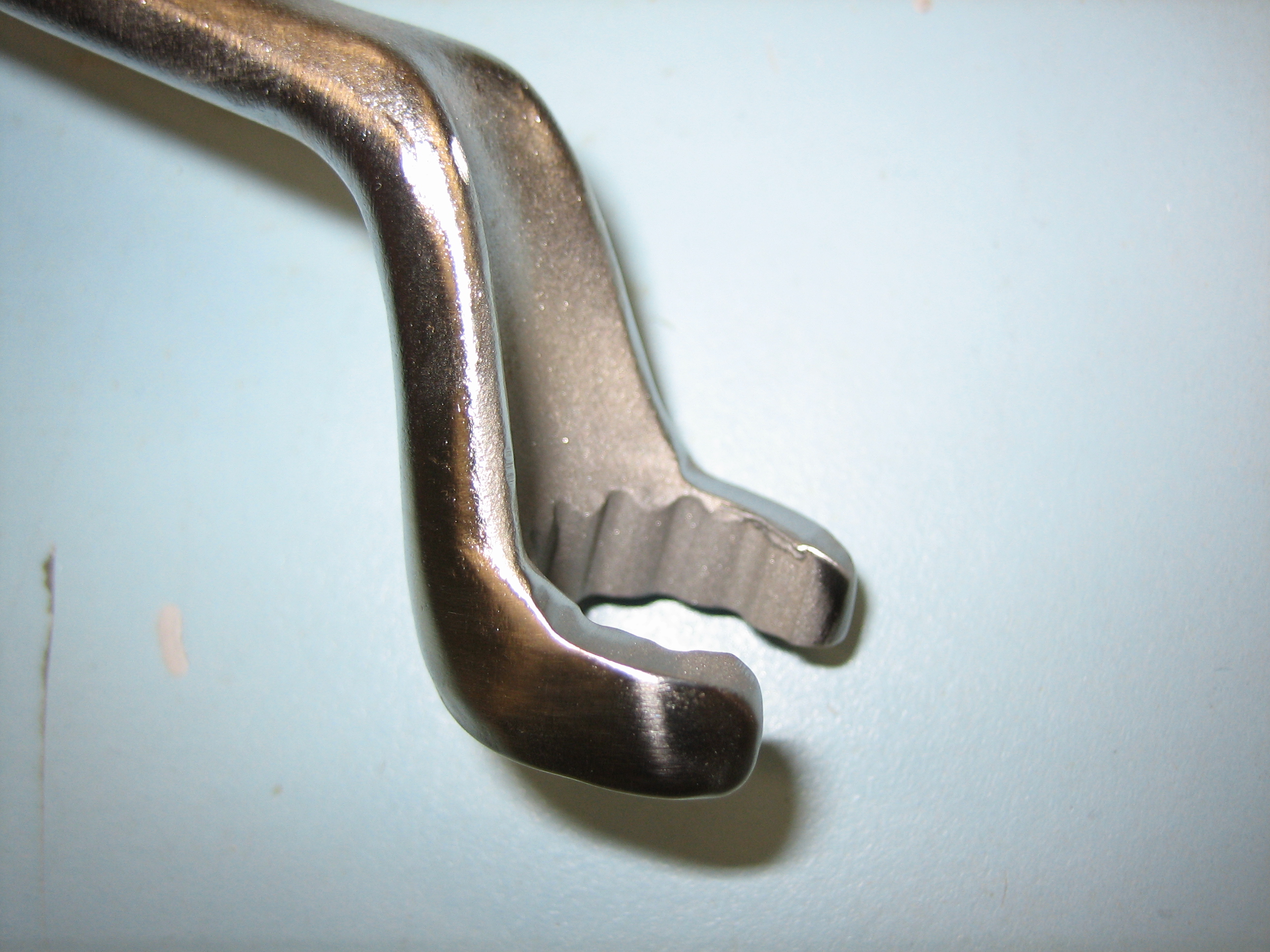
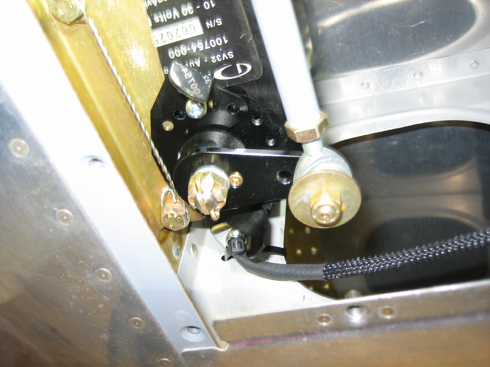
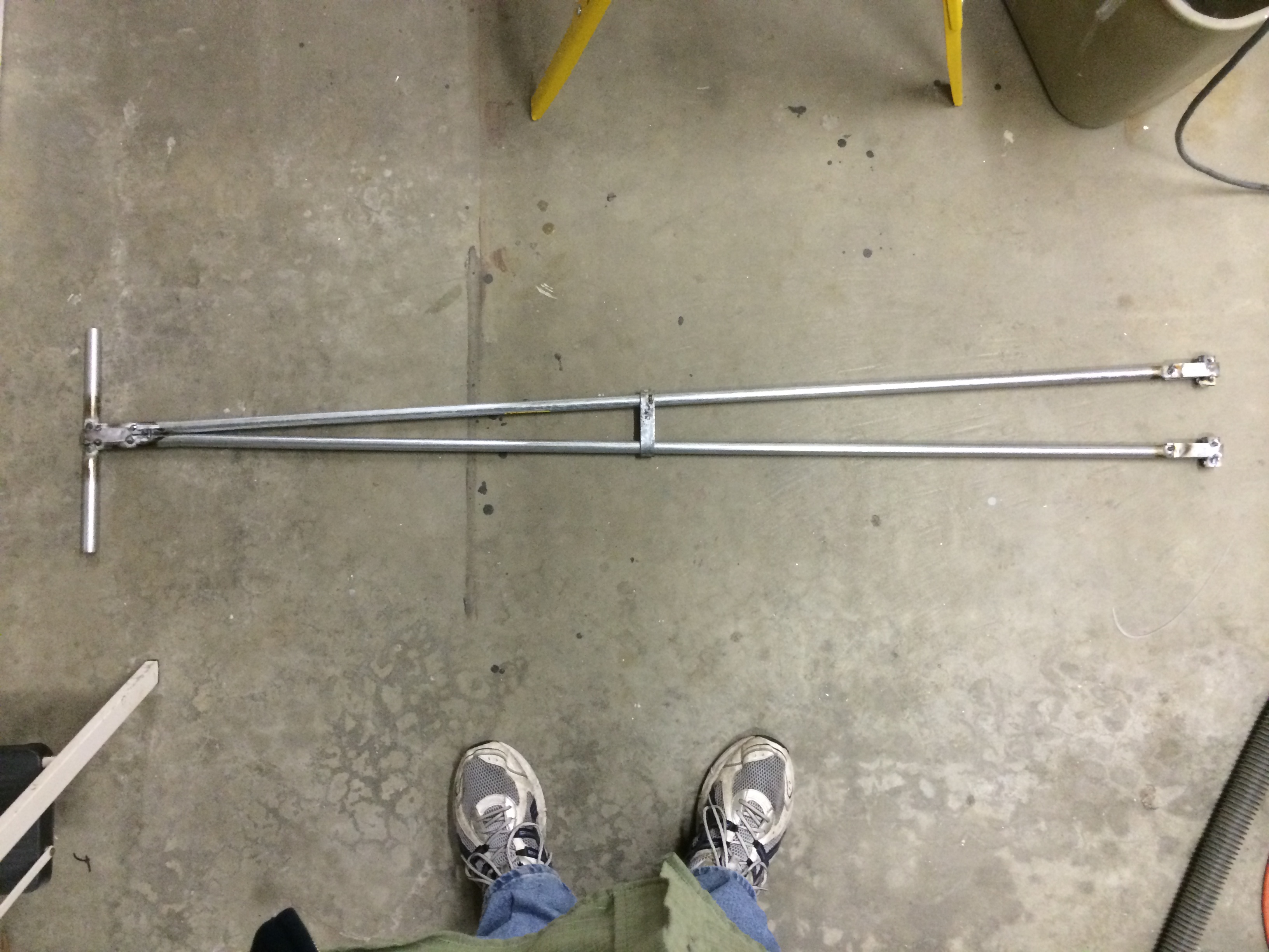
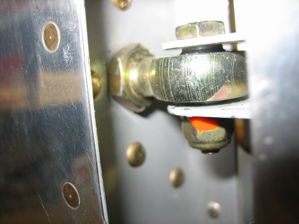
Another builder noticed that the jam nuts on the empennage bearings weren’t torque sealed.  Although I modified a tool to fit in here, I wanted to modify it further before torquing these down for good.

Several builders noticed that my brakes weren’t safety wired.  I had intentionally put this off since I thought I might need to pull the wheels off again, but I don’t think I have any need now before first flight.

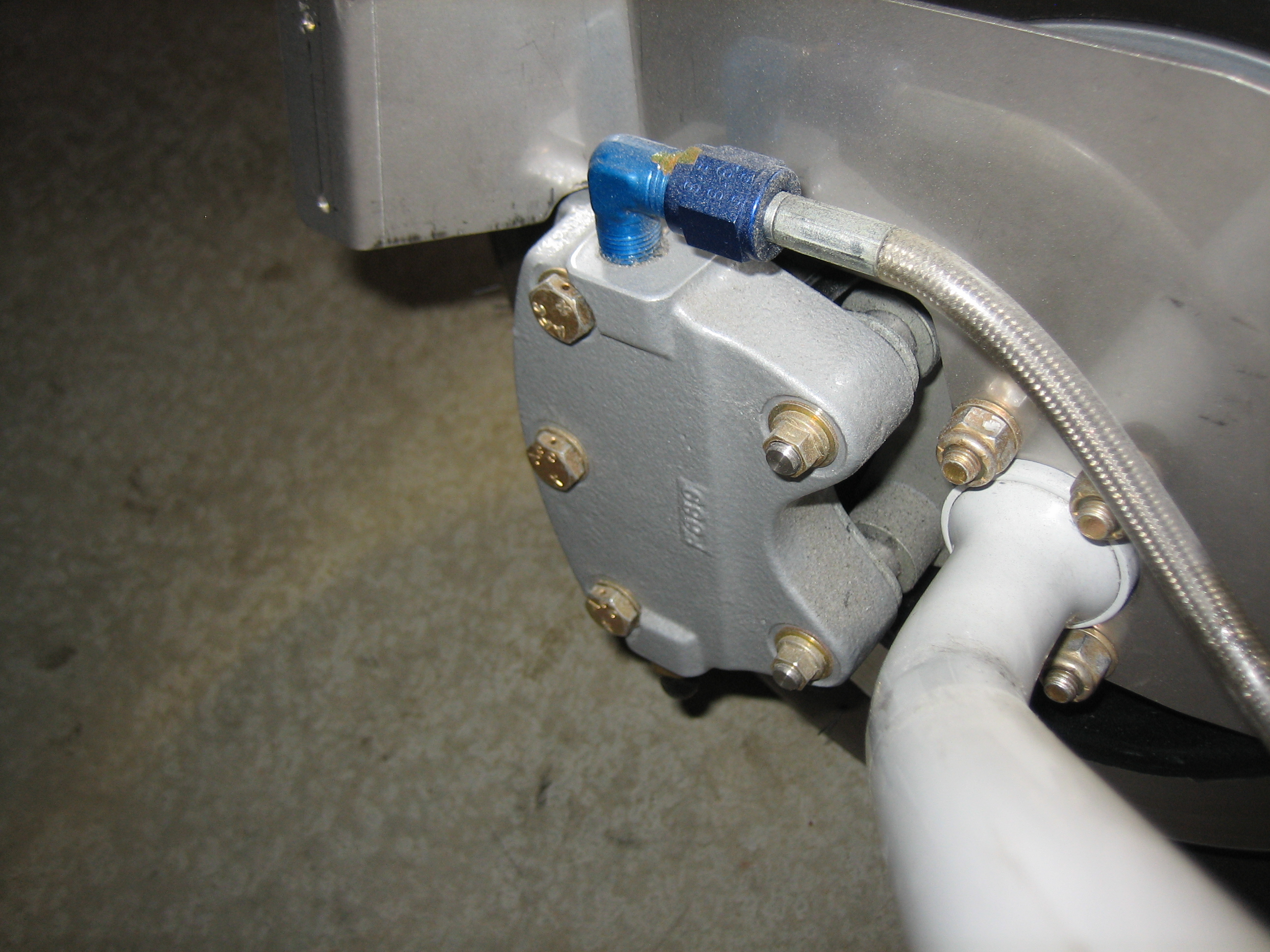
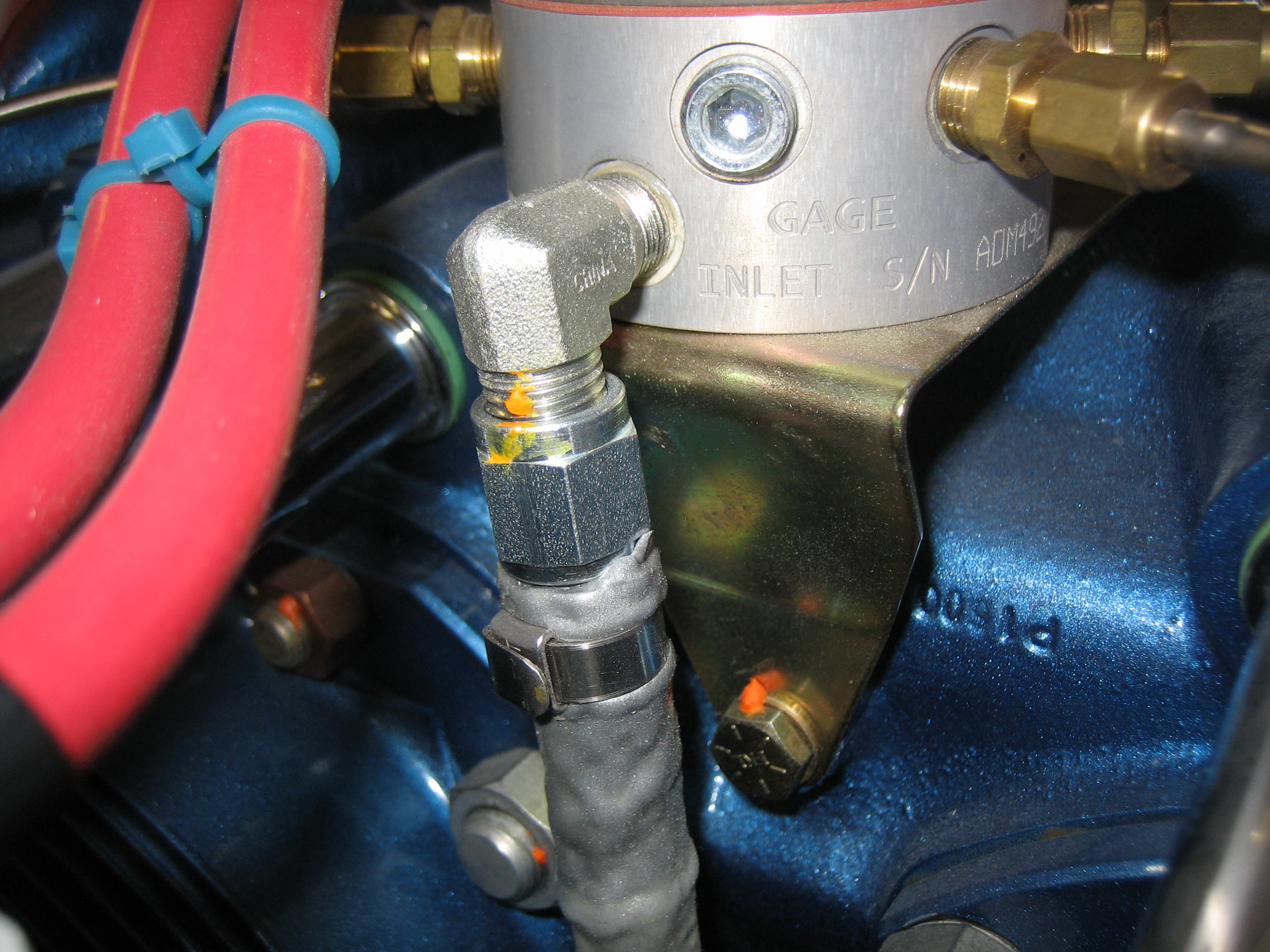
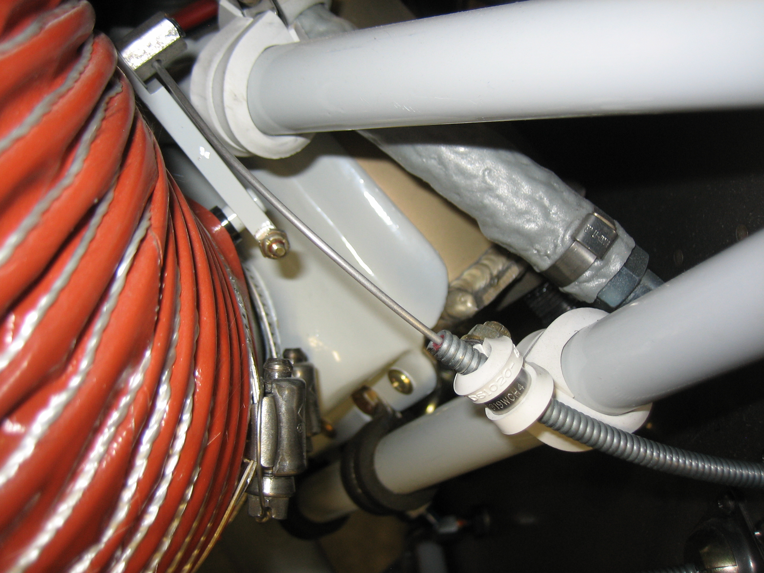
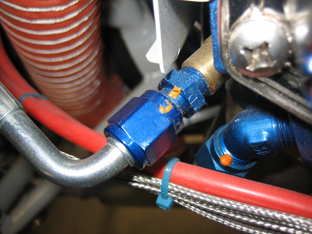
A builder noticed the torque seal was broken on the inlet to the spider.  I had pulled this off before first engine start because I wanted to run some fuel through the line to flush any debris out so that it wouldn’t clog the injectors.  We hooked the line back up before the engine run, but I didn’t put a torque wrench on this then.

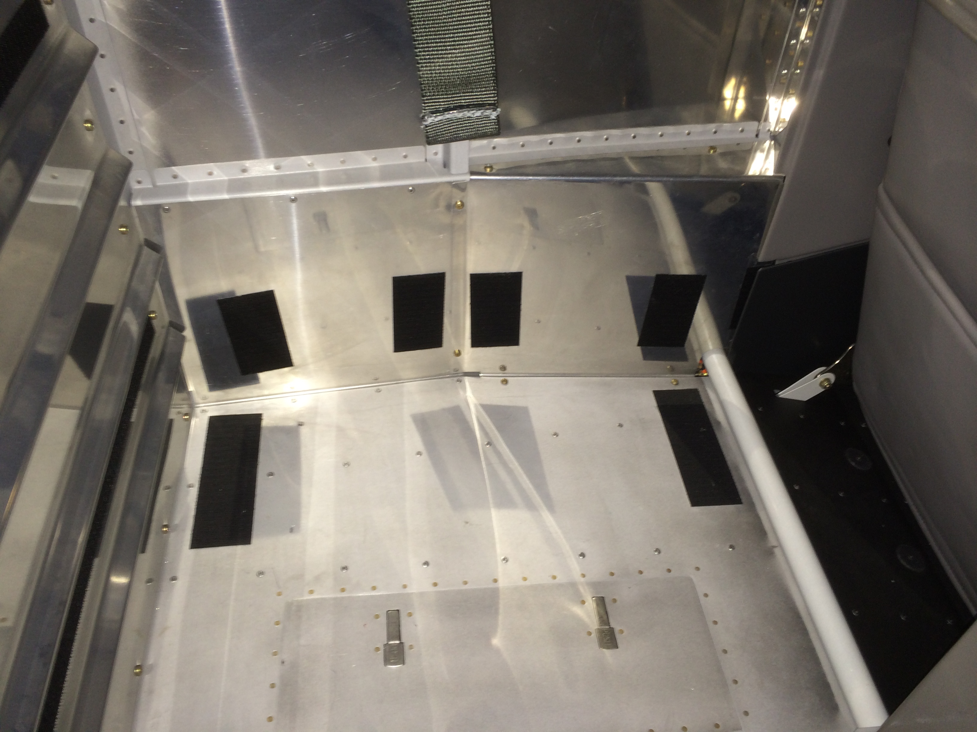
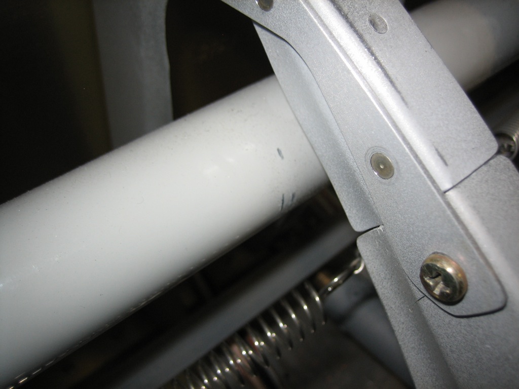
When I was doing the final adjustment of the control sticks, I noticed that the torque tube that connects the control stick was slightly rubbing on the seat ribs.  The builder that also spotted this said it is worse when people are sitting in the seats, so you really want some clearance here.  Fortunately, I made this section removable on all four of these ribs.  I’ll pull these off and remove some material to get a good 1/8″ or so between the ribs and the tube.

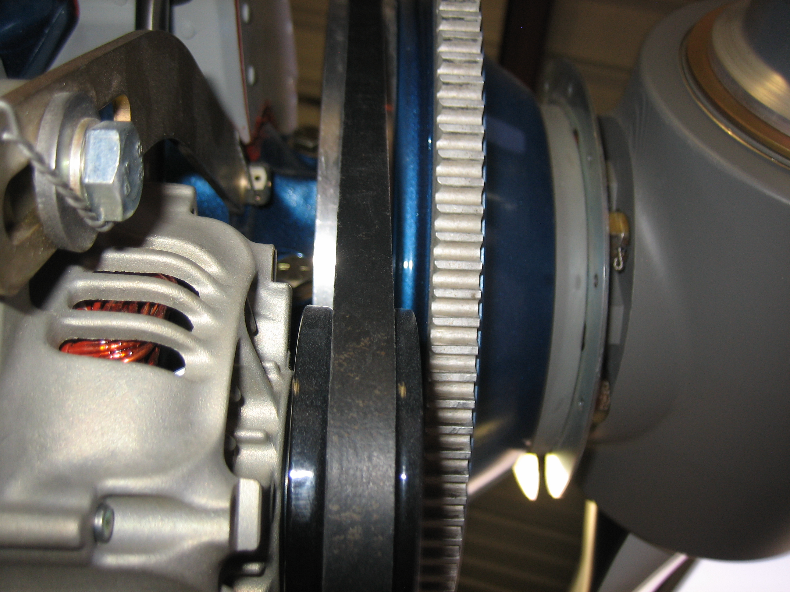
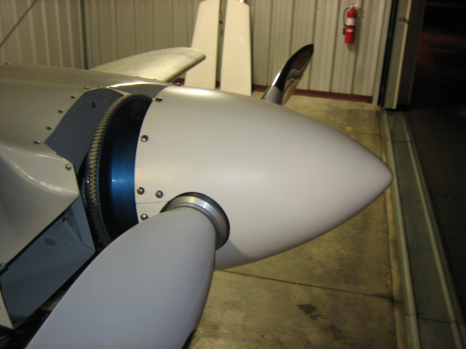
Finally, let’s move on to the things I hadn’t caught.  I couldn’t get a great picture of it, but a couple of people noticed that the alternator pulley wasn’t perfectly aligned with the flywheel.  This will not only make the belt wear faster, it also is apparently hard on the alternator bearings.

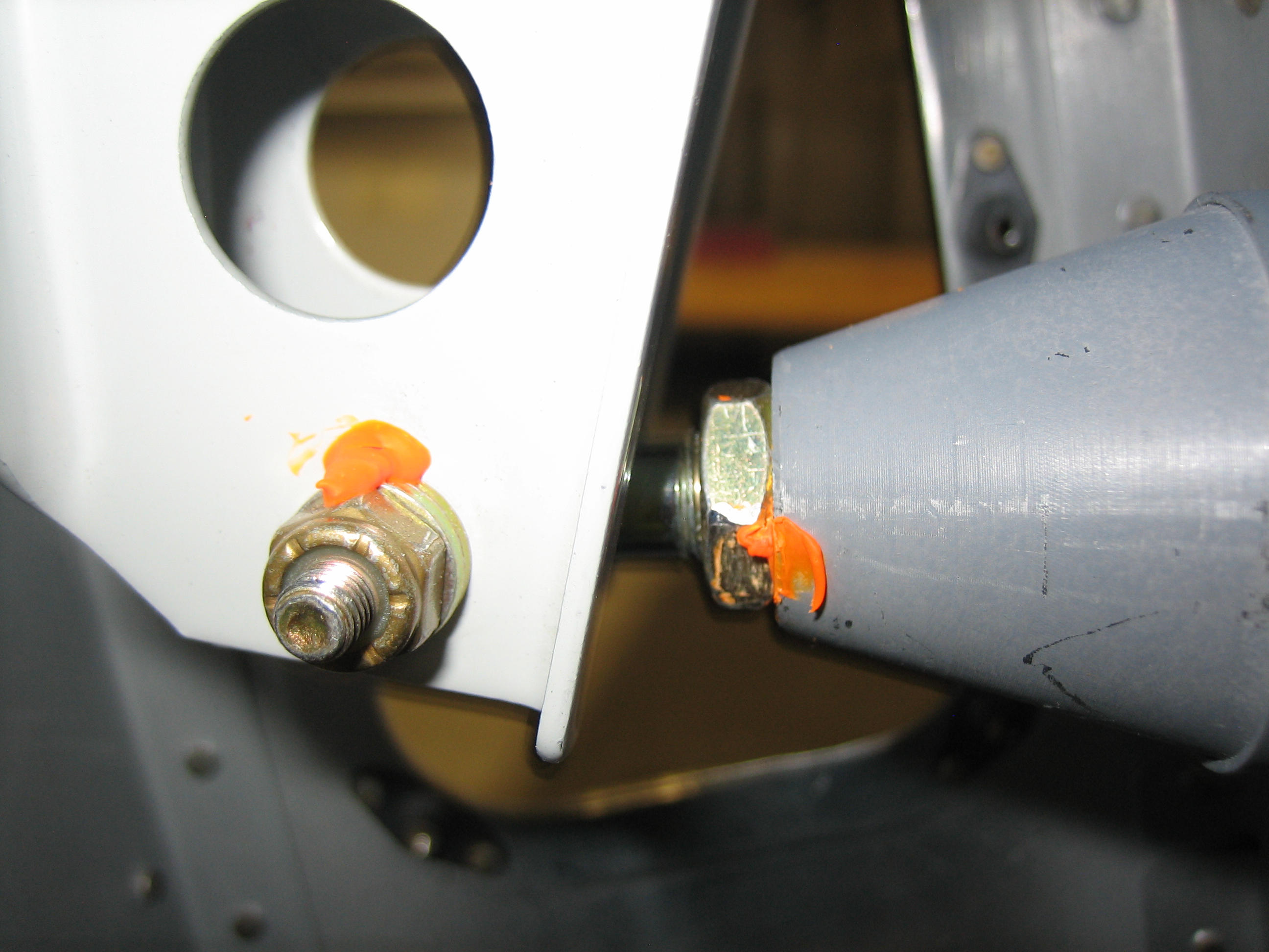
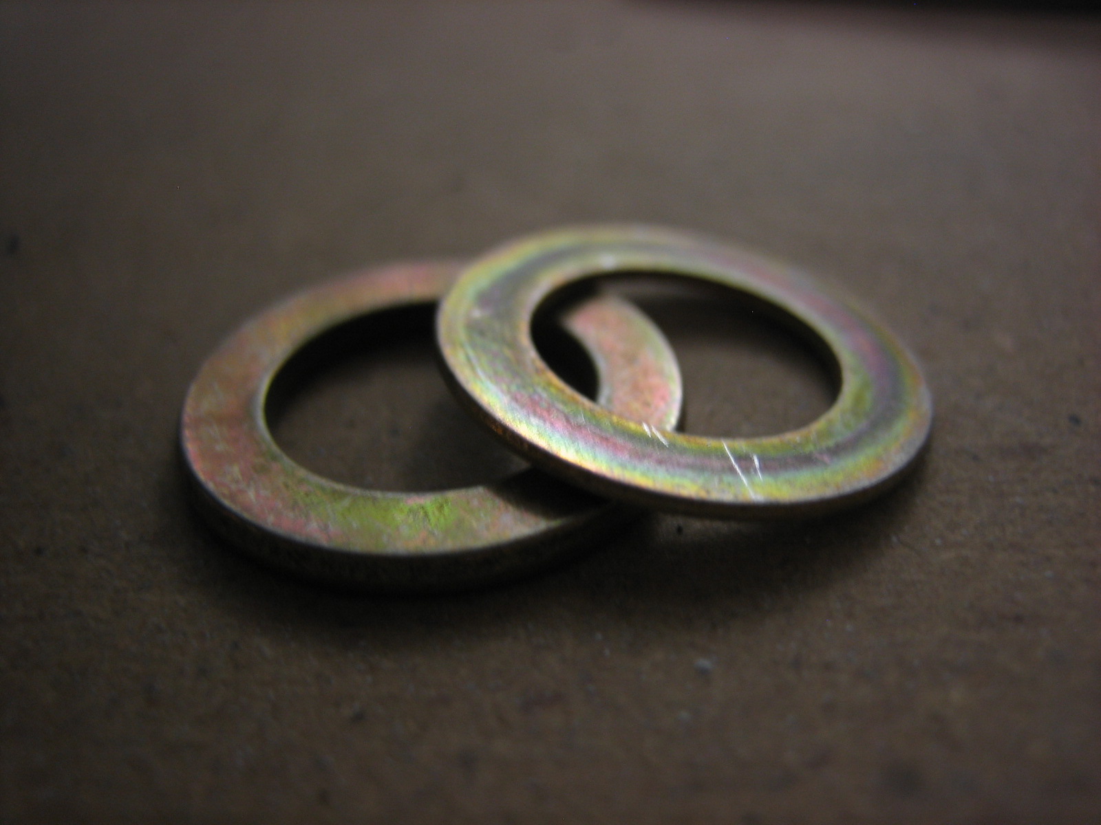
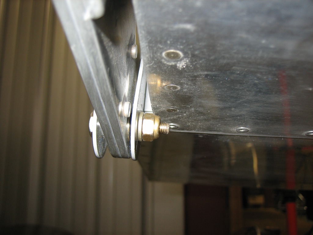
There are four thread showing on the outer aileron bolt.  I’ll probably have to add another washer here.

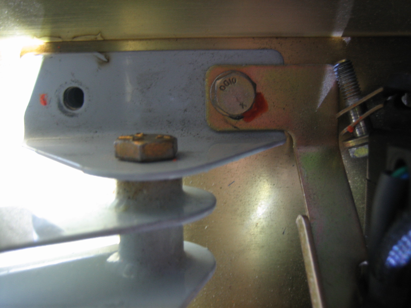
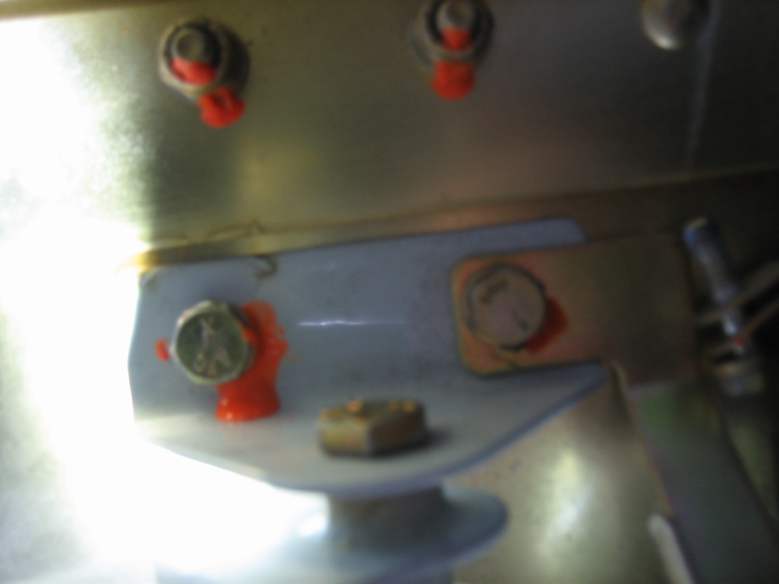
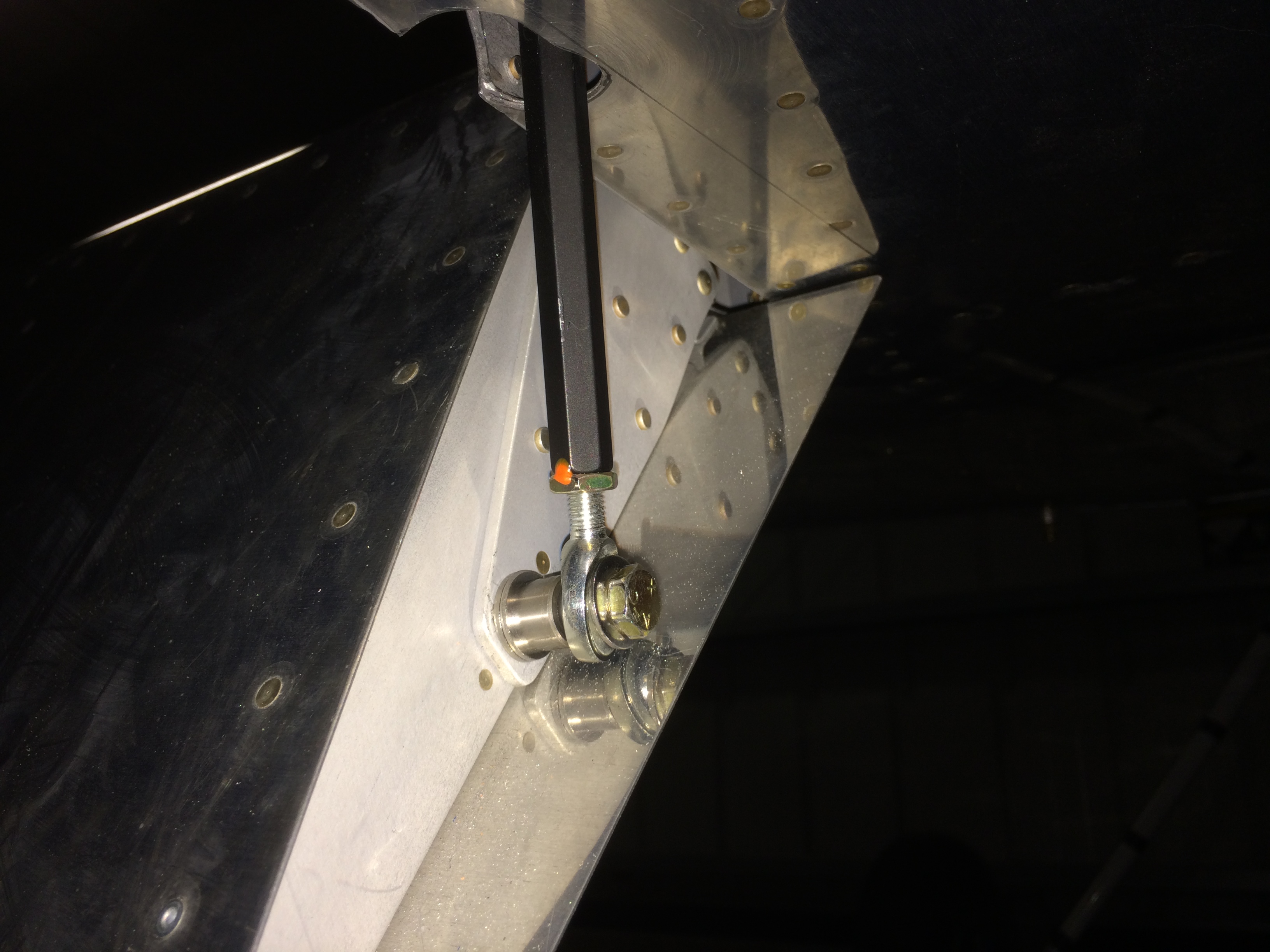
There are also four threads showing on the bolt attaching the pushrod to the elevators horns.

The torque seal was also broken on the manifold pressure hose.  I don’t recall why I removed this, but I’ll need to retorque and seal this.

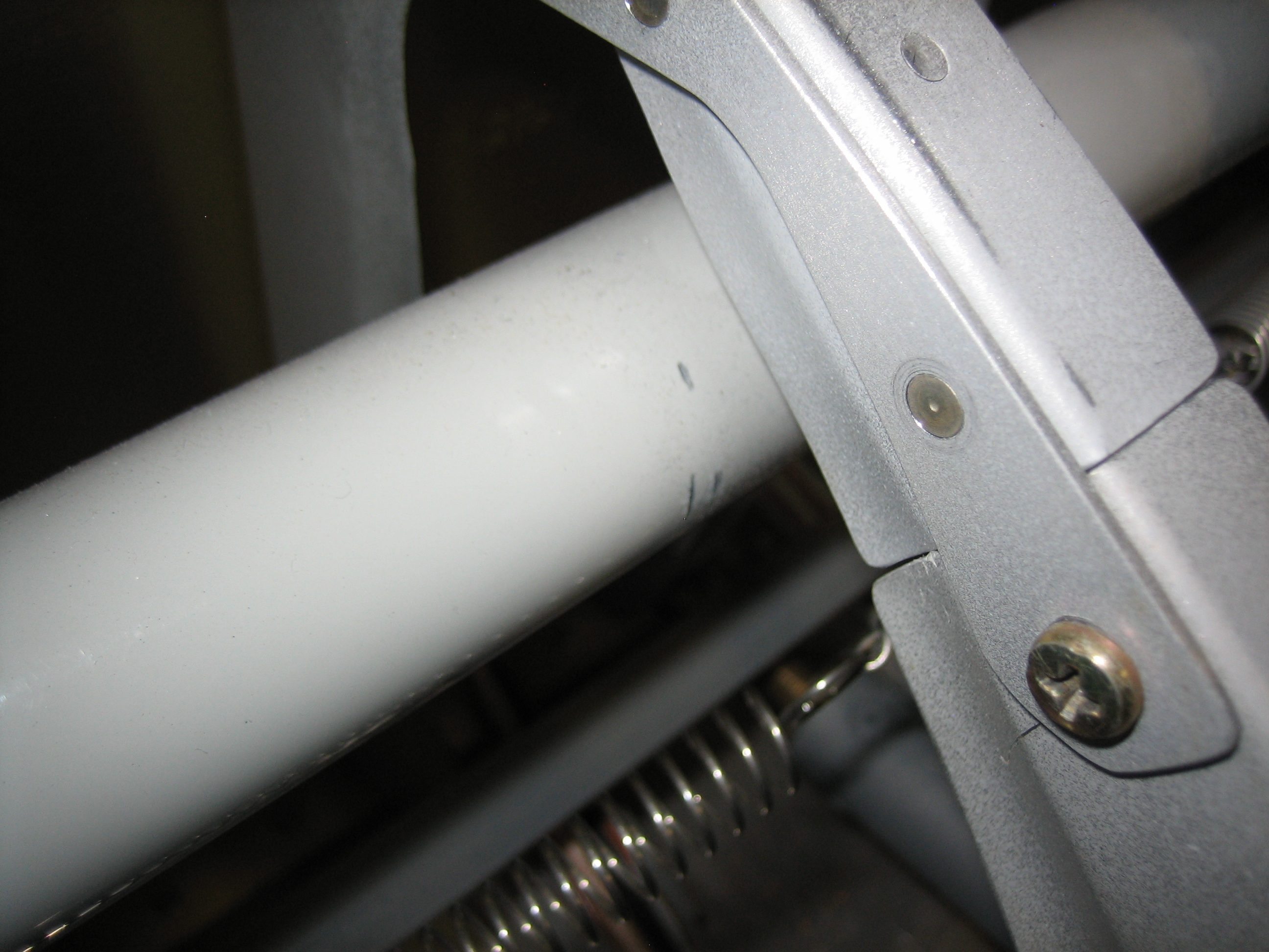
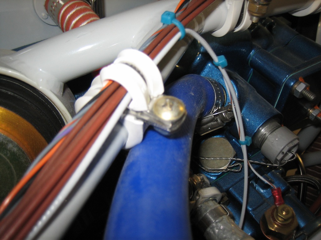
The cushion clamp anchoring the cable sheathing on the oil cooler butterfly valve wasn’t gripping the sheathing well enough and was allowing the cable to move.  I’ll need to swap out this for a non-cushion type clamp.  There was also not enough thread showing on the bolt holding these adel clamps together.

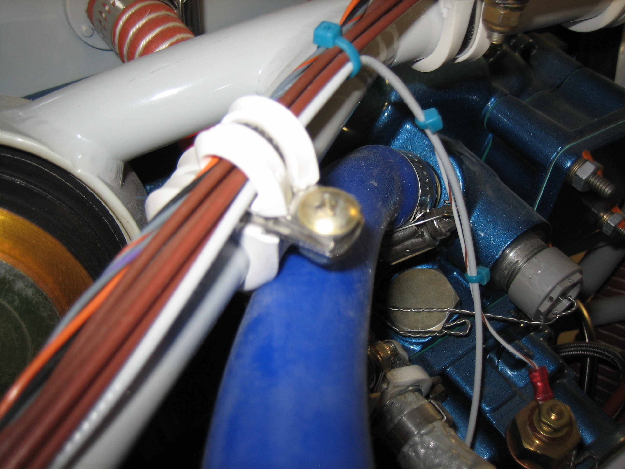
The crankcase breather hose was rubbing on the adel clamps securing wires to the upper engine mount tubing.  I’ll probably add another adel clamp to this group to keep this from chafing.

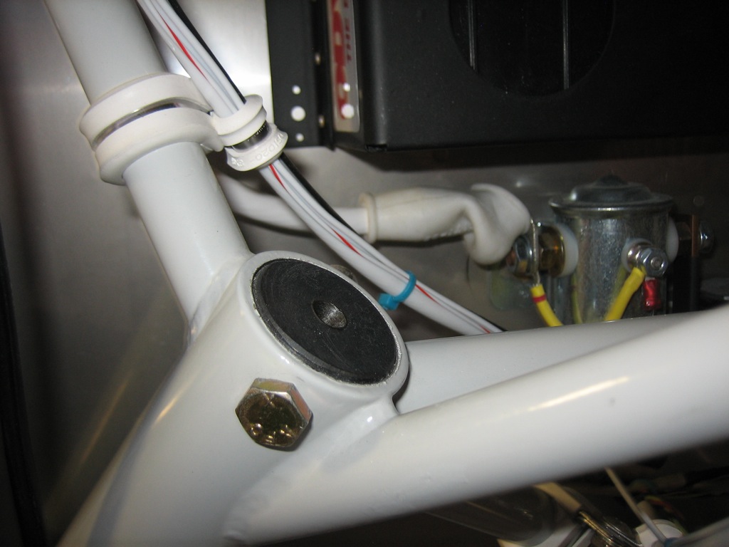
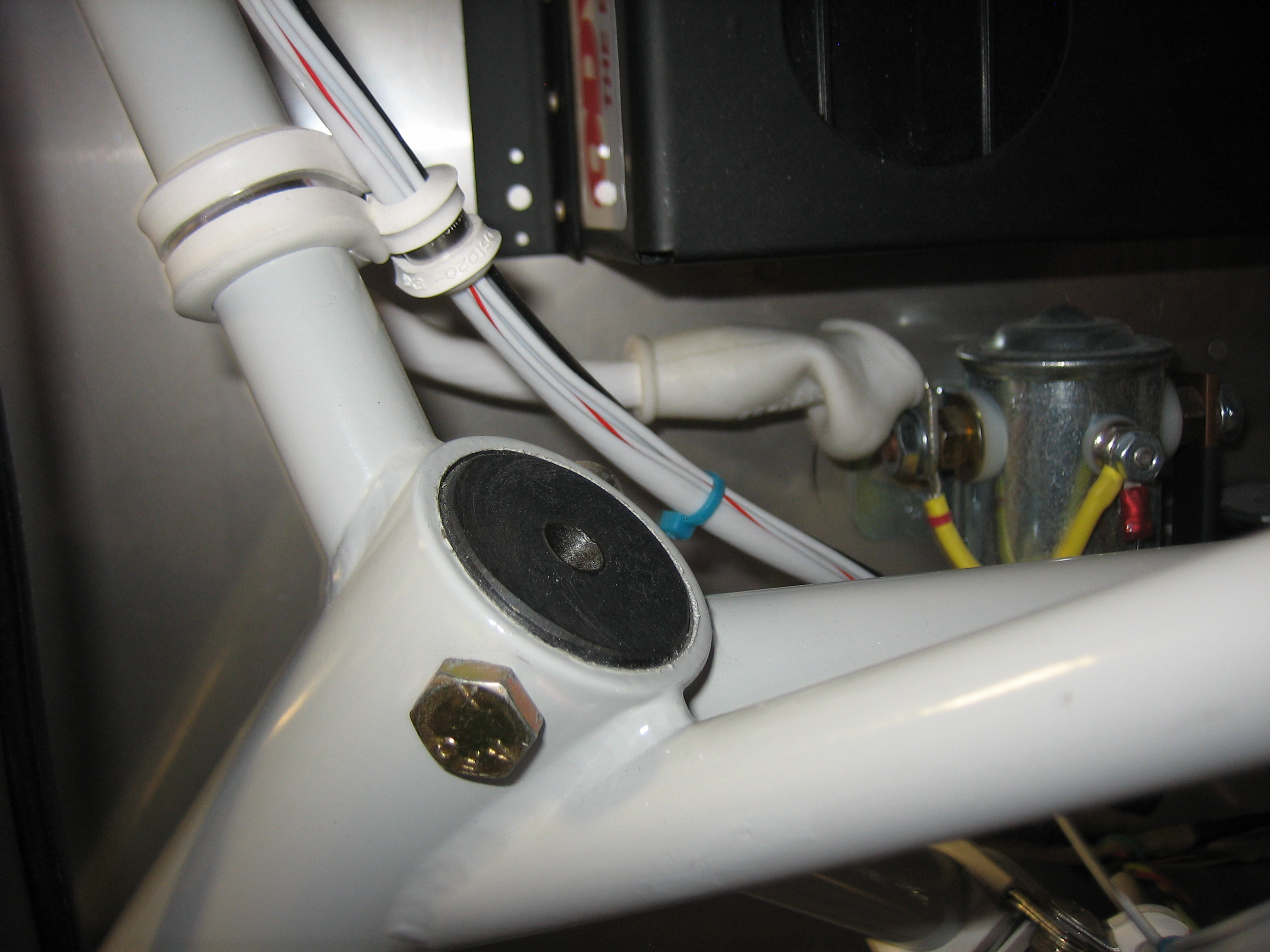
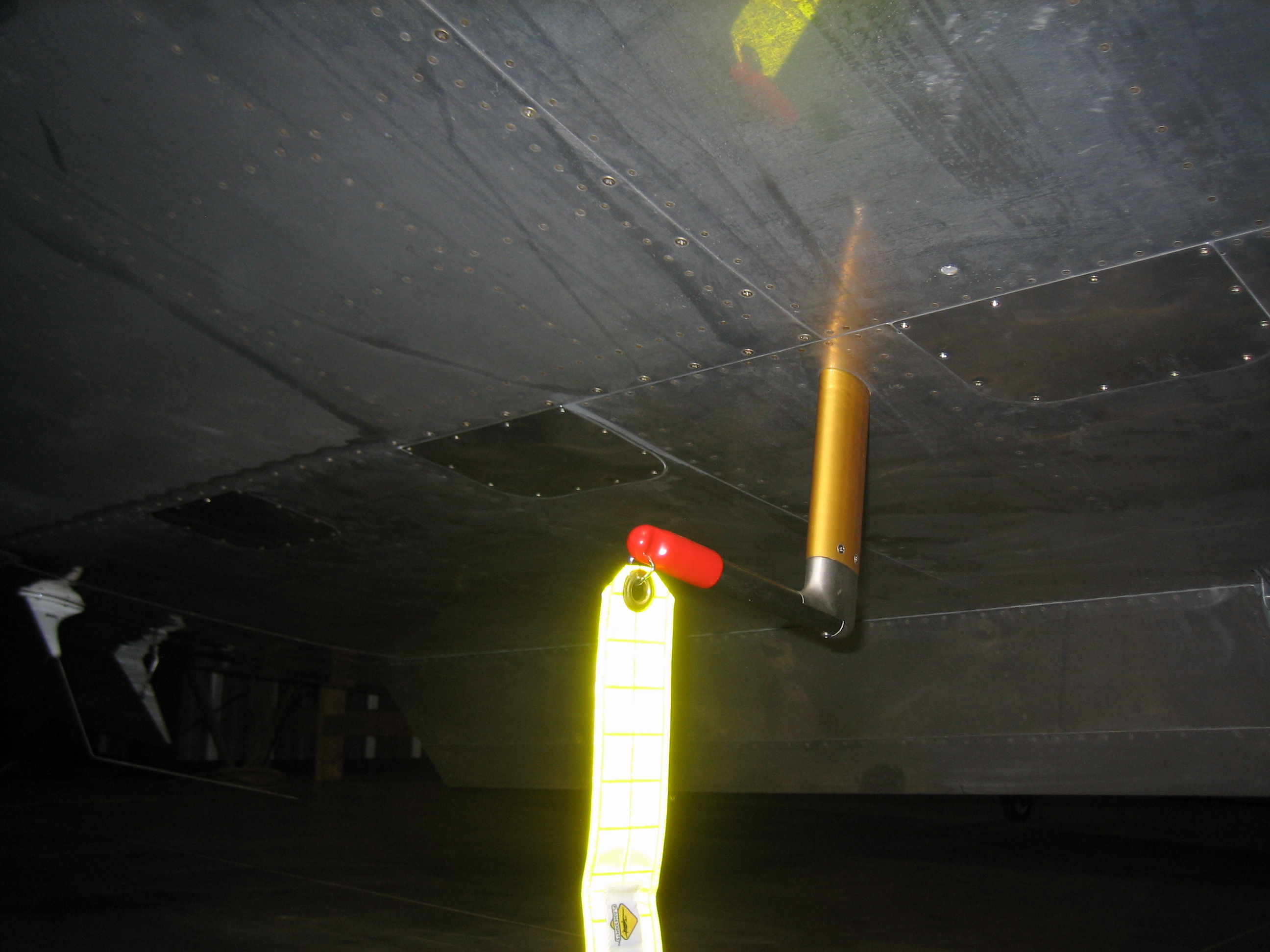
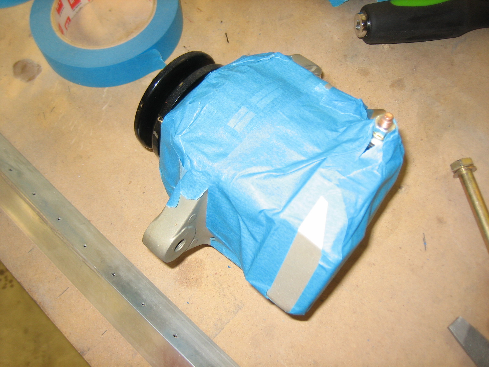
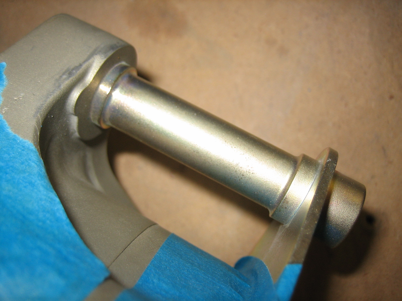
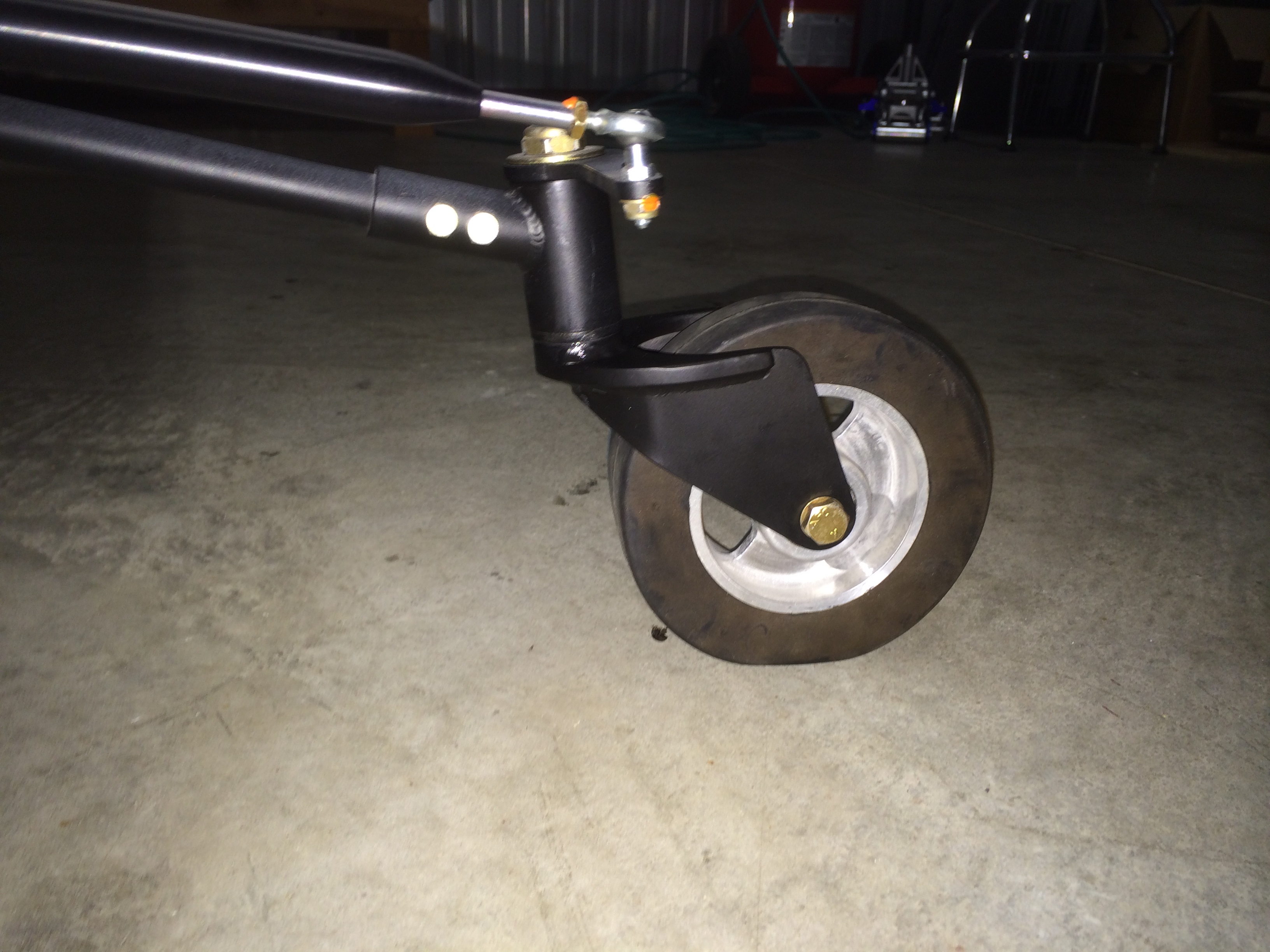
Apparently, the top of the gear leg will rust if left unfinished like this.  I’ll clean it and paint it with the touch-up paint that Van’s sells to match the powder coat on the engine mount.

Put Together Paperwork for DAR

I spent a little time tonight wrapping up the paperwork for the DAR who will be inspecting my airplane.  From the upper left, we have the registration, 8130-6, notarized 8130-12, program letter, weight & balance, three-view and condition inspection.  I emailed everything to him tonight and am planning on meeting with him this Sunday.

Prepping Plane for DAR Visit

I got started tonight by taking a couple of more weight and balance measurements.  I had forgotten to include the plenum, but I decided to also throw the wheel pants and gear leg fairings on at their approximate position.  All of that helped move the CG forward 0.22″, but increased my empty weight to 1110.  After that, I took a measurement with me in the plane to find out exactly where my CG is.  Unfortunately, I’m 0.24″ aft of where Van’s says the pilot’s CG should be.  This had the effect of moving the plane’s CG back by 0.05″.  The net result is that the CG will be roughly 0.17″ forward of where I calculated on Sunday.  That still puts me 2.48″ aft of the forward CG limit, so I’ll still have to add some weight up front.

Afterward, I pulled everything off or out of the plane to get it ready for inspection.  I’ve still got a fair number of items to knock off the list before that happens though.

Airworthy!

I met with the DAR this morning.  After he inspected the plane, we went over the paperwork I submitted and then reviewed my operating limitations.  Finally, he issued my airworthiness certificate, so the plane is officially airworthy.  We spent a little time afterward discussing my preparations for flight testing and covering the test plan for my initial flight.

My airframe logbook also gets an entry stating the plane is airworthy.

With the final inspection done, I started buttoning up the plane to get it ready for flight.  First up, I installed the wing inspection panels (all but one which I’ll discuss below).

I then moved on and installed the wing root fairings.  The adhesive I applied the other day seems to have worked out well.

Before installing the last wing inspection panel, I needed to install the aileron servo stop.  I couldn’t get the bracket in place without enlarging the center slot a bit.  After ensuring it would fit, I shot a fresh coat of paint on to keep this from rusting.

Finally, I installed it on the servo.  Slipping it behind the arm and under the safety wire is a little tricky and it will only go one way.  I installed an AN960-10 washer between the bracket and the servo under each mounting screw to space the bracket away from the servo by the thickness of the servo mounting bracket.

Update: I subsequently caught that the safety wire on the lower bracket bolt was reversed.  This is another issue that I’m surprised wasn’t caught at the builder inspection party.  There wasn’t much room to work in there, but I managed to get the wire reversed.

While doing a thorough pre-flight before buttoning up each panel, I found this missing bolt (you can see the bolt over on the right).  I had removed this a long time ago because I was using it to hold an adel clamp for the servo wires.  When I rerouted the wires, it never occurred to me to check this.  I’m really surprised that this wasn’t found during my builder inspection party.  There were a couple of guys that were doing a pretty thorough inspection with mirrors and flashlights.  Regardless, I had always planned on doing a complete control integrity check from end to end, so I wouldn’t have made it to first flight without catching this.

I installed a new bolt (and way too much torque seal because I couldn’t see it well).

With nothing left to do on top of the engine, I installed the plenum for the last time before first flight.

I also installed the spinner.

Since I need to shift the alternator back by about 3/32″, I pulled the mounting bolts and removed it.

I’ll need to file off the aft end of the pivot shaft (not visible here), I taped up the alternator to ensure no metal filings make their way inside.

This shaft is about 2.992″ long, and I need to take about 0.094 off the right end of this shaft.

I can then use one AN960-616 and one AN960-616L washer to make up the difference.

After grinding down the shaft, you can see that I have the same length when I now include the washers.  I’ll reinstall the alternator tomorrow and re-tension the belt.  This ended up being way easier than I expected.

More Reassembly and New Tailwheel Fork

I finished adjusting the flap pushrods and final torqued them.  I had to open up the holes a bit more to make room for the bolt head when the flap is just about fully up.  I taped the ailerons to the wingtips and the elevator in the neutral position to use as a reference and then adjusted the flap pushrods so that the flaps align with the ailerons.  Finally, I lubricated these rod end bearings.

I swapped out my tailwheel fork for the one from JDAir.  The person I spoke with there claimed I would save about a pound over the Bell fork I had, but the savings was just over 1/2 pound.  I’m still glad I made the switch, but disappointed that the savings wasn’t what they claimed.

I installed the baggage wall and then taped up a ziploc bag as the temporary holder for my registration, airworthiness certificate and phase 1 operating limitations.

With the flaps adjusted, I could now install the flap covers.

Finally, I vacuumed out the inside of the plane and installed all of the forward interior components.  I’m not going to bother installing the interior pieces in the baggage area for phase one (except for the final weight and balance).

Fabricated Tow Bar

I picked about $10 worth of electrical conduit and fittings and welded up a tow bar down at the TechShop.  The crosspiece that you see in the center can slide up and down the tubes to apply the clamping force that will keep the tow bar attached to the tailwheel bolt.  This should be super simple to attach and remove.  Basically, you just line up the fittings with the bolt and squeeze the tubes together.  The crosspiece will automatically slide down the tubes and lock the tow bar in place.  To release, just pull back on the cross piece and the fittings will pop off.  I made the tow bar 5′ long because a shorter tow bar tends to hit the bottom of the rudder.  Hopefully 5′ will be long enough to avoid that.

Full Power Engine Run

I didn’t get any pictures, but I did the first full power engine run today.  I’ve been having an issue with high oil pressure even though the adjustment screw is backed all the way out.  The main thing I wanted to determine was where the pressure would top out.  It turns out that with the oil pressure regulator turned all the way down, it peaked at 103 PSI at 1800 RPM and stayed there all the way up to 2700 RPM.  AeroSport power said the red line should be at 95 PSI, so it’s clearly too high.  I’ll call them tomorrow to see what I should do about this.

I also started adding some glass to the lower empennage fairings to make them line up with the upper fairing.  I needed to stiffen up the leading edge so that I could add some lightweight filler without it cracking due to the fairing being so flexible.

Finally, I spent some time using the MicroMesh kit on the canopy to remove a few spots of paint overspray and some minor scratches.  I worked all the way down to the 6000 grit sandpaper.  I’ll use the polish tomorrow.