Replaced Pitch Servo Shear Screw

Sometime in the last couple of weeks, I noticed that the pitch servo wasn’t controlling the plane. I did some ground diagnosis and determined that the shear screw had sheared or some reason. I don’t recall any forces that would have caused this, so I can’t say why it happened. Dynon sent out a shear screw replacement kit a few days ago and I stopped by the airport this morning to install it and put the plane back together.

It’s amazing that this tiny cross section of brass is critical to the autopilot being able to control the aircraft.

I reassembled the control arm and tested the autopilot servo. Everything worked as expected, so I reinstalled the interior and updated the logbook.

Replaced Tailwheel

On one of my fuel stops on my recent trip back to TX and OK, I felt a weird vibration on landing, and it turned out that a chunk of the rubber from the tailwheel had broken loose. There had always been a defect in the rubber from the time the tailwheel was new, but I thought it was cosmetic. It lasted over 8 years and nearly 500 hours of flight time though, so I can’t complain too much.

In the meantime though, FlyBoy Accessories started selling this 4″ lightweight tire that is 13.5oz lighter than the 5.5″ tire above. That moves my CG an additional 0.13″ forward which should further help with the aft CG issue I’ve always had.

10th Annual

I wrapped up the 10th annual on the RV tonight with about 611 hours on the plane. The plane has been virtually flawless during the past decade, but there are always some items that need to be repaired or replaced.

First up is the tires. I’m a little surprised I got 10 years out of the original set, but I’ve always let it roll out on landing and avoided heavy braking where possible. I did flip them to opposite wheels at one point to even out the wear, but they were pretty well worn now, so I decided to replace them. Here you can see the new tire on the left with the original tire beside it.

The snorkel had a bunch of cracking paint and flaking filler, so I removed it and sanded it back to the bare fiberglass before repainting it. I originally applied filler and sanded it to make it smooth, but the filler was delaminating. I’m not sure why it didn’t bond better, but it should be more robust now.

Finally, I replaced the air filter. These K&N filters are supposed to be lifetime filters, but some of the wires were starting to break on my old one for some reason.

Biggest Annual to Date

The plane was down for over a month with this annual. Part of that was work as we had our developer’s conference a couple of weeks ago and that’s always a busy time of the year. I’m also running my boss’ team while he’s out, so that’s taking up much more of my time. The other factor is that I addressed several more issues than I normally do during the annual.

I spent the most time tackling several issues firewall forward. The first is that one of my upper exhaust mount support brackets broke. If you’ve been a long-time reader of this site, you might remember that I originally flattened and bent the stainless steel tubing (per instructions from Vetterman), but that broke and I replaced it with these steel brackets made from 18 gauge mild steel. This lasted over 600 hours, but it was apparently still too thin.

I fabricated four new brackets out of 12 gauge steel which will likely last longer than the airplane. I replaced both upper brackets even though only one of them bad broken. I have two spares now in case the lower brackets ever crack. Fortunately, the broken bracket didn’t cause any additional damage.

The oil dipstick tube was originally installed with a paper gasket that is notorious for leaking. It’s also been a minor irritation, but since the plane down for awhile and I needed to order some other things from Aircraft Spruce, I went ahead and ordered one of the Real Gasket RG-72059. Hopefully this will address the issue.

My engine has been sagging for some time. It has progressed to the point now that the alternator pulls is cutting a shallow groove in the lower cowl. I’d been putting it off because I expected it to be a pain, and boy was I right. This is the right side and access is reasonably good here. The left side though was a bear. I could barely see the nut behind all of the stuff in the way. To gain access, I ended up removing the #4 intake tube, disconnecting the mixture cable, and removing the mixture cable support bracket. Even with all of that out of the way, I could barely get my fingertips against the nut, and it was incredibly challenging to get any tool on it to loosen it. I eventually got it off though and the bolts slipped out easily.

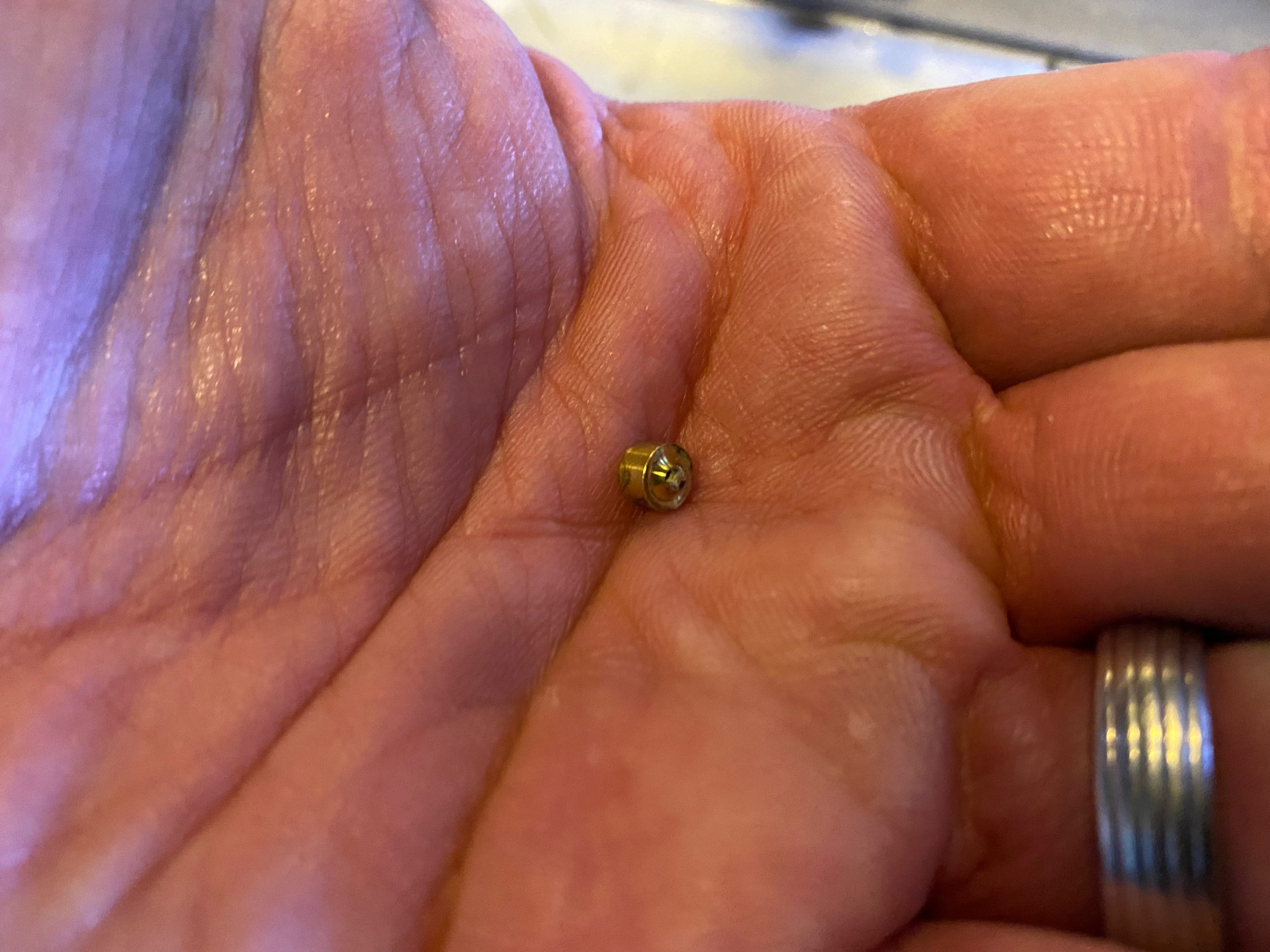
The spinner was down about 1/4″, so my hope was that a single AN970-7 washer would be enough. It would be an enormous pain to have to install and remove these multiple times to fine tune the thickness of a shim. Fortunately, this worked out well. When I originally installed the engine mount bolts, I borrowed a friends bolt alignment bullet. I’m not sure where he got it, but it helped bring everything into alignment as we drove the bolts through. I didn’t have access to it anymore, so I whipped up a version on the lathe that worked pretty well.

You can see now that the spinner is nicely aligned with the cowling.

While I had the baggage wall out, I installed some expanding foam insulation in the bends to reduce the airflow from the tail. This should help a little bit with cabin temps at higher altitudes.

We recently added LEMO jacks to our Bonanza. I previously converted my Bose A20 headsets to LEMO connectors, and I’ve been using these adaptors in my RV. I originally installed my headphone jacks on the subpanel. This kept the headphone jacks out of the way, but it makes working on them difficult as it requires crawling under the panel. I probably should have left myself a reasonable service loop of wires, but I was trying to keep the plane light and didn’t do that.

Out of curiosity, I disassembled the LEMO adapter and found out that the internal alignment pieces exactly matched the panel mount LEMO jacks that I’d purchased.

Even the rear shell threaded on correctly.

I realized that this meant I could continue to use my LEMO adapters if I simply replaced the LEMO end with the panel mount jack. The only modification I needed to make was to install a power wire onto the unused pin in the jack and route it out of the back of the connector.

This let me install the LEMO jacks on the panel. I wanted to install them in a location that was as out of the way as possible, and ended up choosing the far edges of the panel. Here’s the pilot’s side.

And here’s the copilot’s side.

There’s a good 1/4″ of clearance from the cable to the gas struts that support the canopy

These can just stay plugged into my original headset jacks and can be unplugged someone ever wants to use their own headset without a LEMO connector.

Added Starlink Mini Antenna

I’ve always had difficulty staying in contact with friends and family when flying. Cell phone coverage is spotty, especially across the western half of the US and when flying at higher altitudes. I often just need to send a message about where I am or what time I’ll be landing, but sometimes there’s something more urgent to deal with like the time my wife desperately needed to get ahold of me.

Starlink recently added a Local Priority plan that works up to 350mph, so I decided to add one to our Bonanza and my RV. Since I’ve been learning Fusion 360, I decided to design a custom mount. The Starlink Mini antenna is not a simple rectangle though, and I don’t own a 3D scanner.


Fortunately, Starlink publishes a 3D model for the Mini, so I used that to design some plastic mounts that fit over each end (the parts in black below), and an aluminum frame that holds the mounts. I used plastic for the mounts since they wrap over the top of the antenna and I didn’t want to interfere with the signal. The plastic will be transparent at the frequencies the antenna operates at (as will the fiberglass wingtips).

The plastic mounts space the antenna off of the frame since the back of the antenna hangs down somewhat.

I uploaded the aluminum frame to SendCutSend and had the part in hand two days later. After some demurring, I shot a coat of primer and paint.

I 3D printed the mounts out of ABS which is quite strong and should easily handle the high temperatures the plane will experience when parked outside in the sun.

With the plastic mounts installed, the antenna nestles neatly inside the aluminum frame.

Here’s the bottom side. It’s honestly quite impressive how well the parts fit. Even the bolt holes in the bottom of the mount lined up perfectly between the aluminum and plastic parts.

The Starlink Mini antenna will operate with an input voltage from 12-48VDC, but I’ve heard it can be sensitive to low voltage. It has higher power consumption during startup, and if the voltage drops, the antenna can restart. To avoid this, I installed a step-up power supply that will take 9-28VDC input and output 30VDC. It’s built for the Starlink, so the output cable has the Starlink specific connector. I elected not to run a separate power wire out for the Starlink, and instead tied it into the strobe power wire.

I riveted the aluminum frame to some angle aluminum that I cut as long as I could to spread the load out as much as possible and limit the rib flexing. The frame angles the antenna away from the rib by 10º; this partially offsets the wing dihedral, but further points the antenna away from the wing by a few more degrees. It also roughly centers the outside edge of the antenna along the height of the rib. Given the shape of the wingtip, this ensures the antenna stays well clear of the inside surface.

I installed the plastic mounts on the antenna and bolted them to the frame.

Finally, I plugged in the power cable and zip-tied the wires.