Fit Forward Bulkheads and Gear Attach Webs

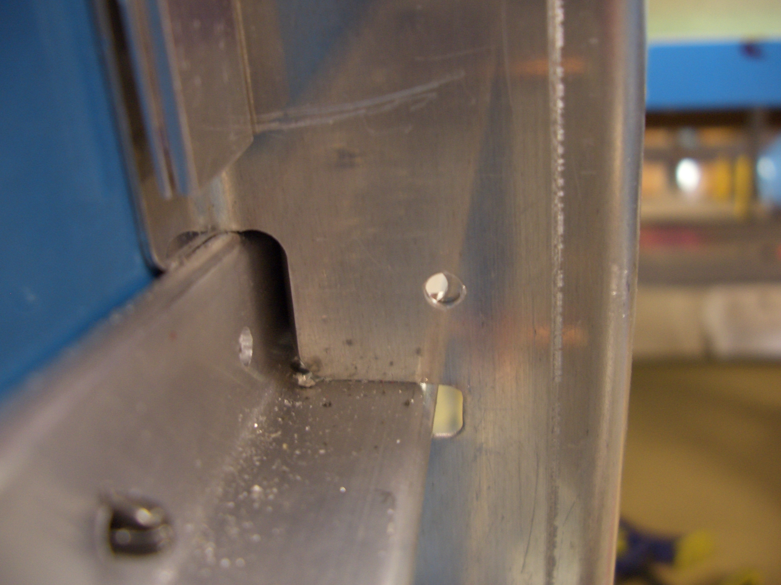
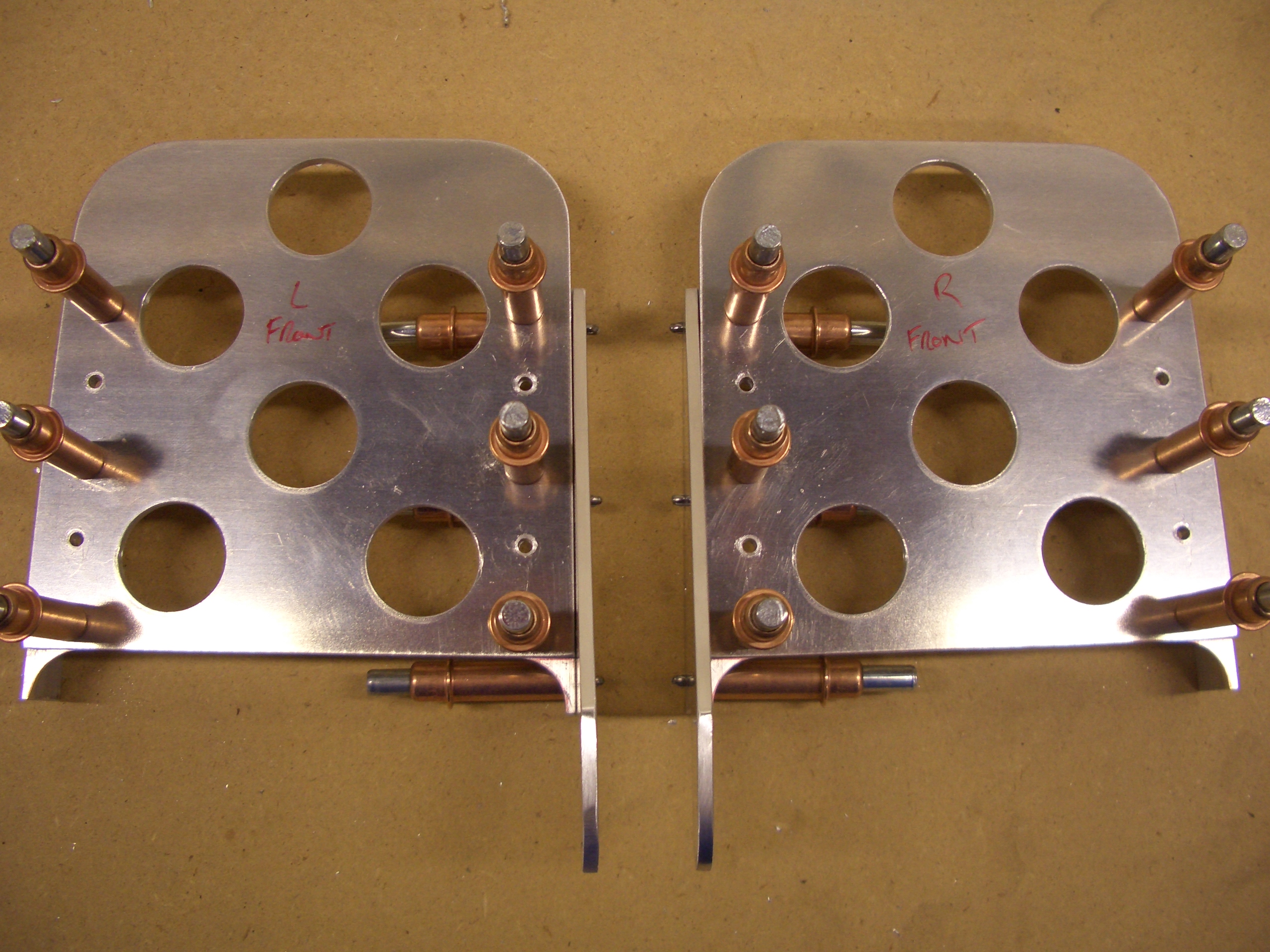
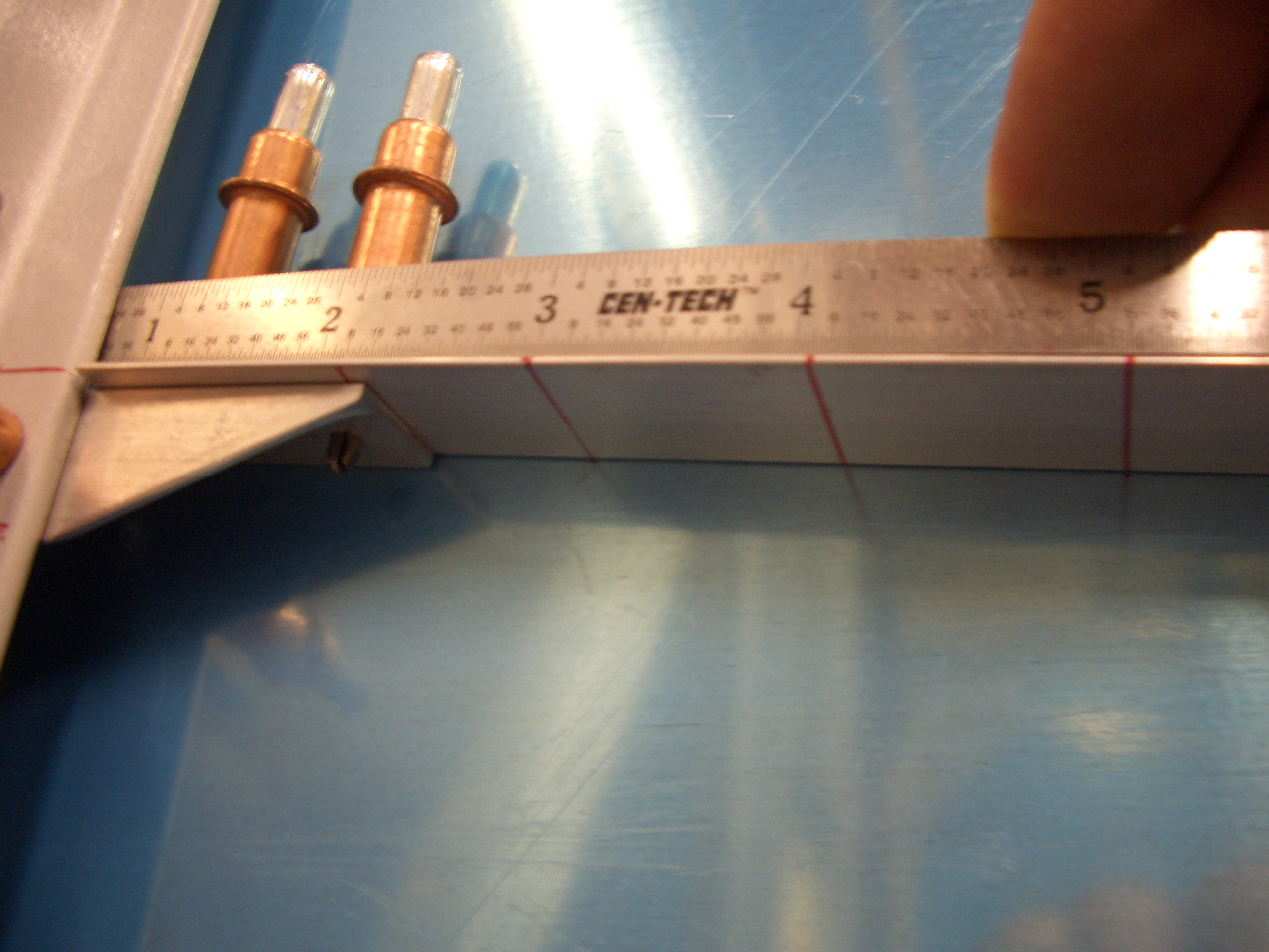
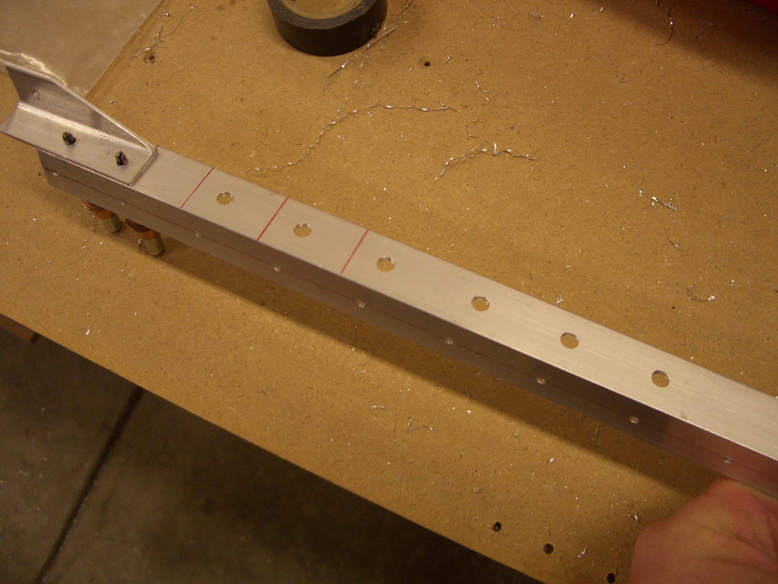
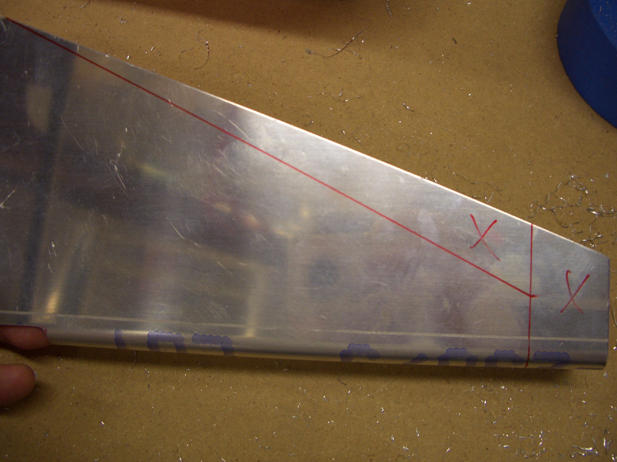
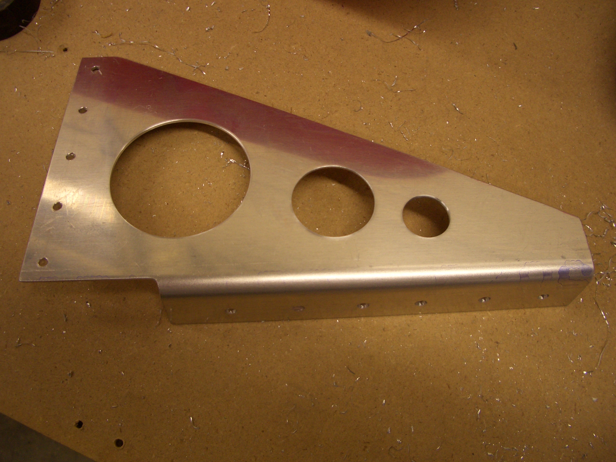
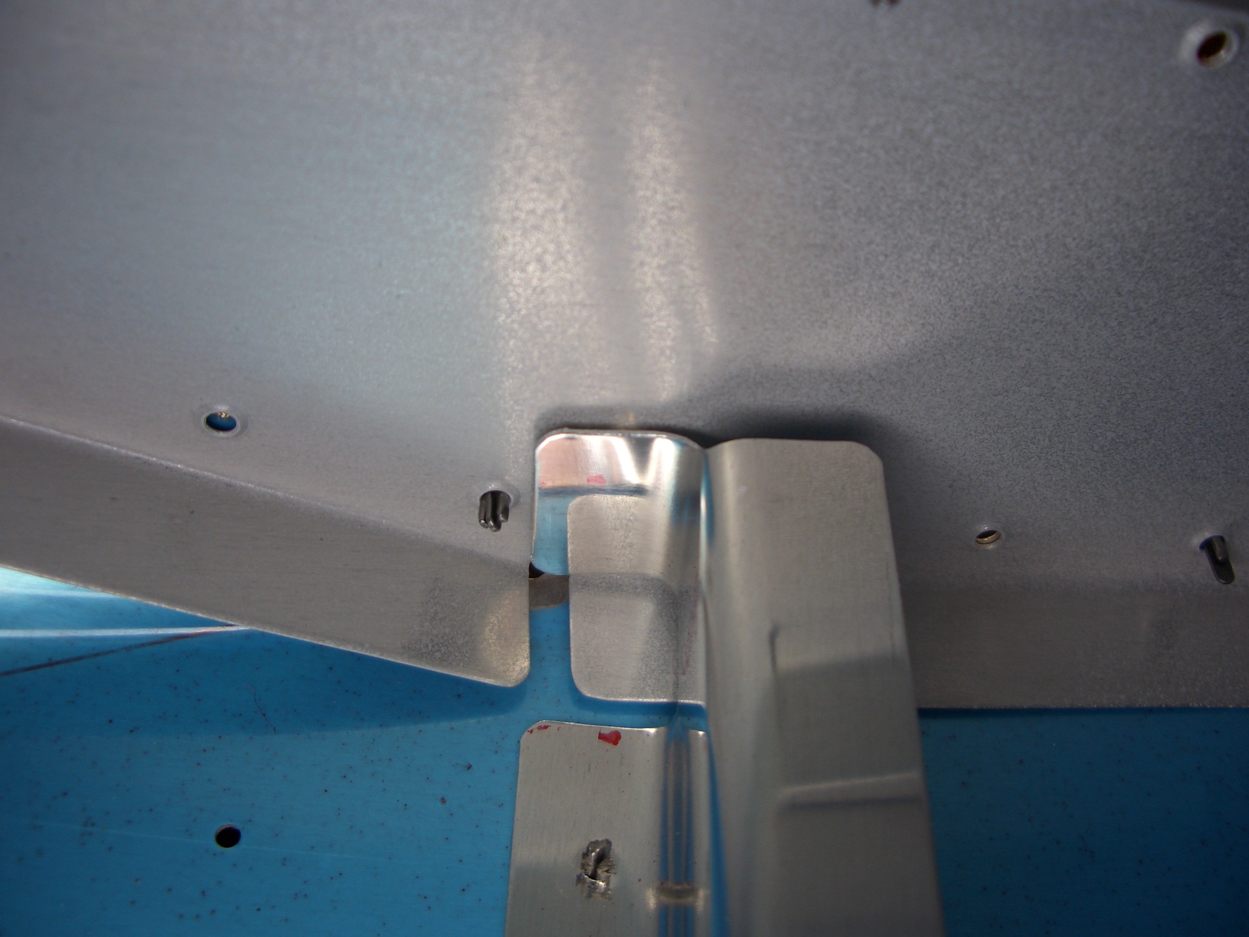
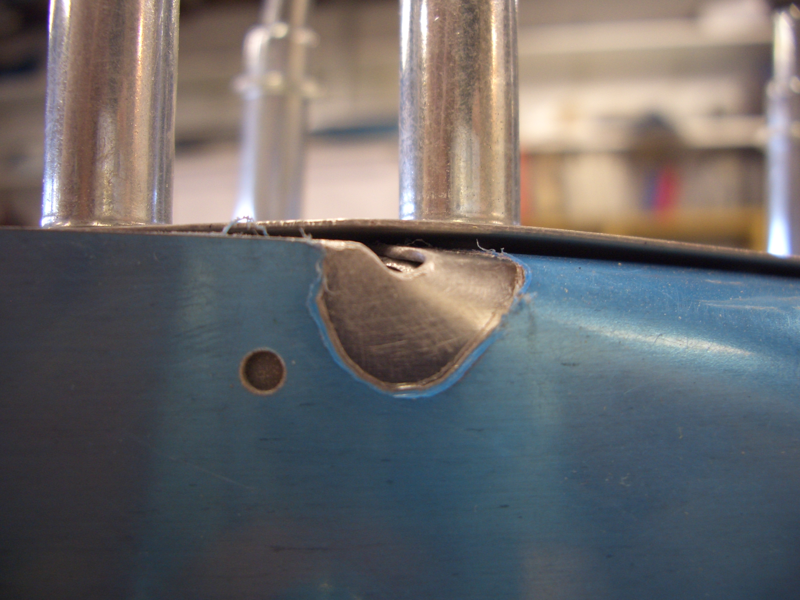
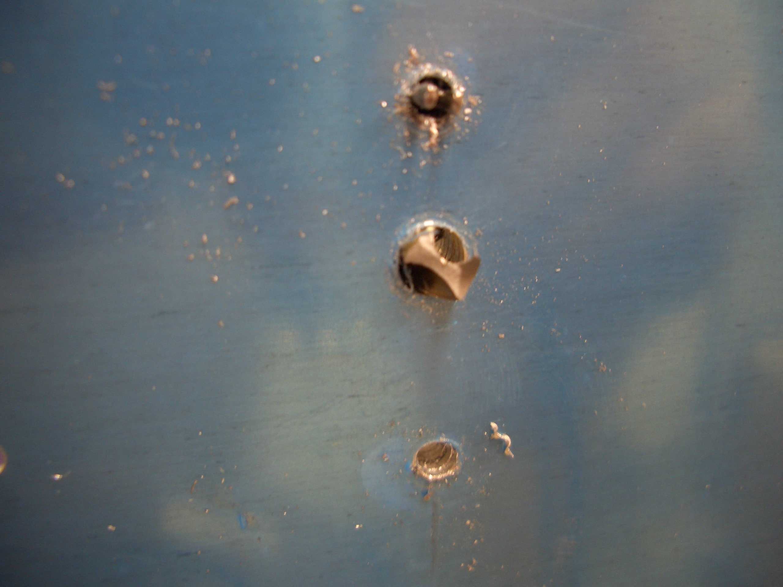
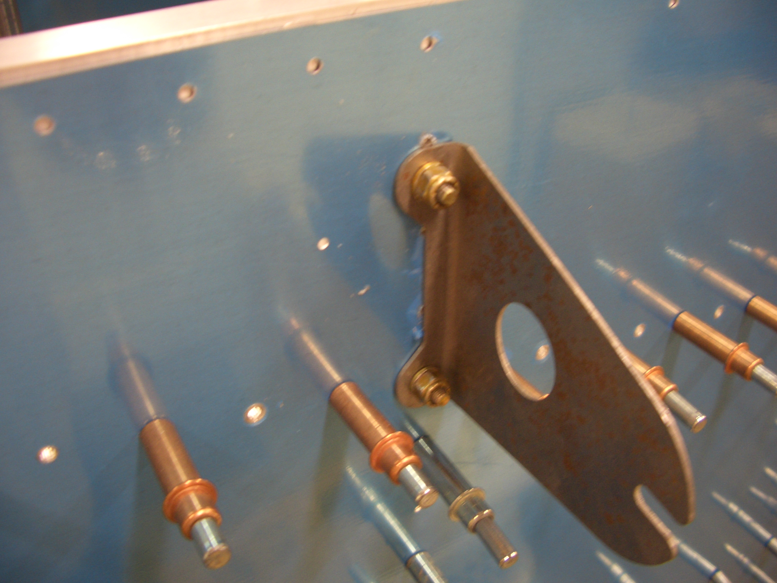
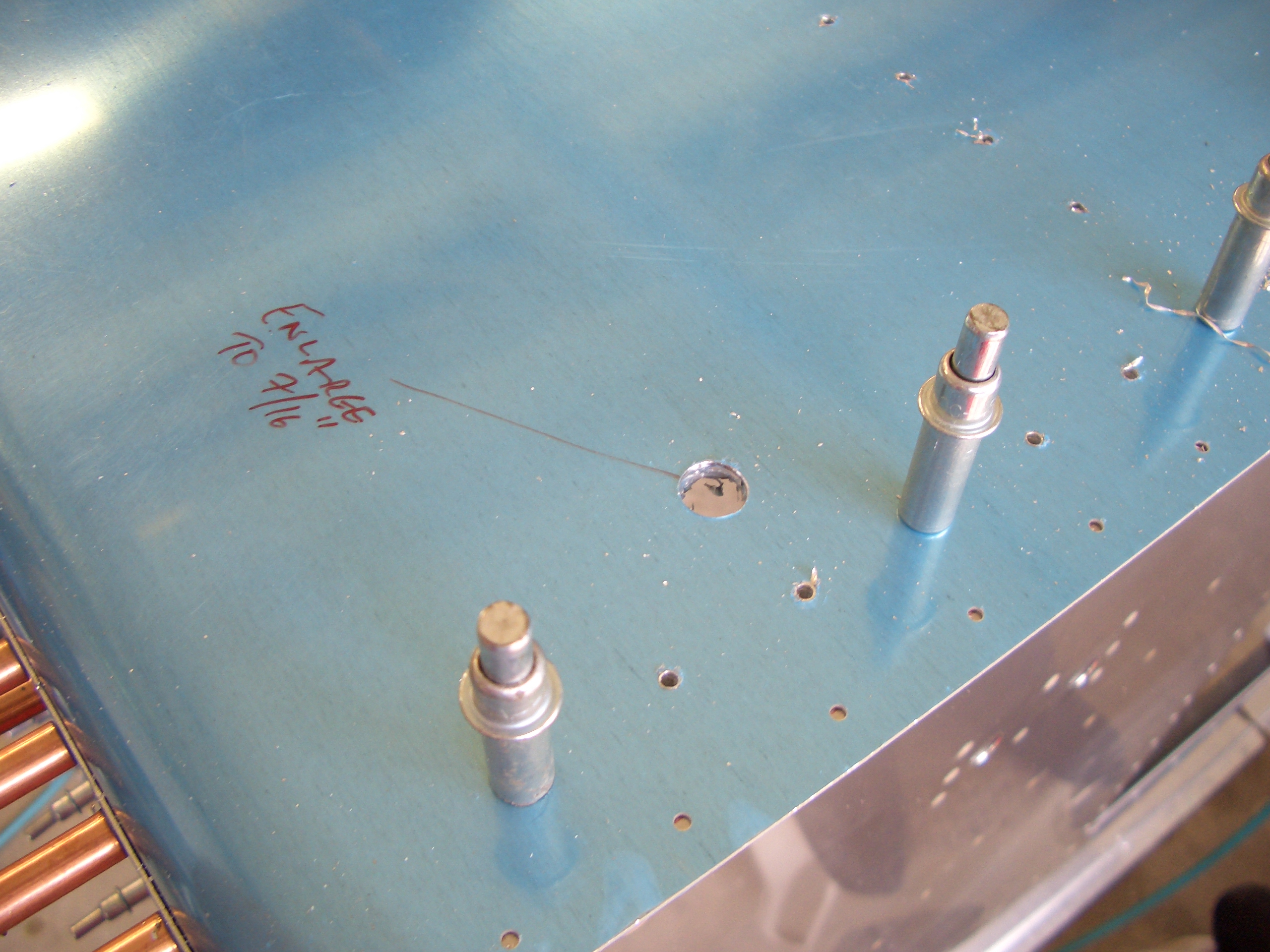
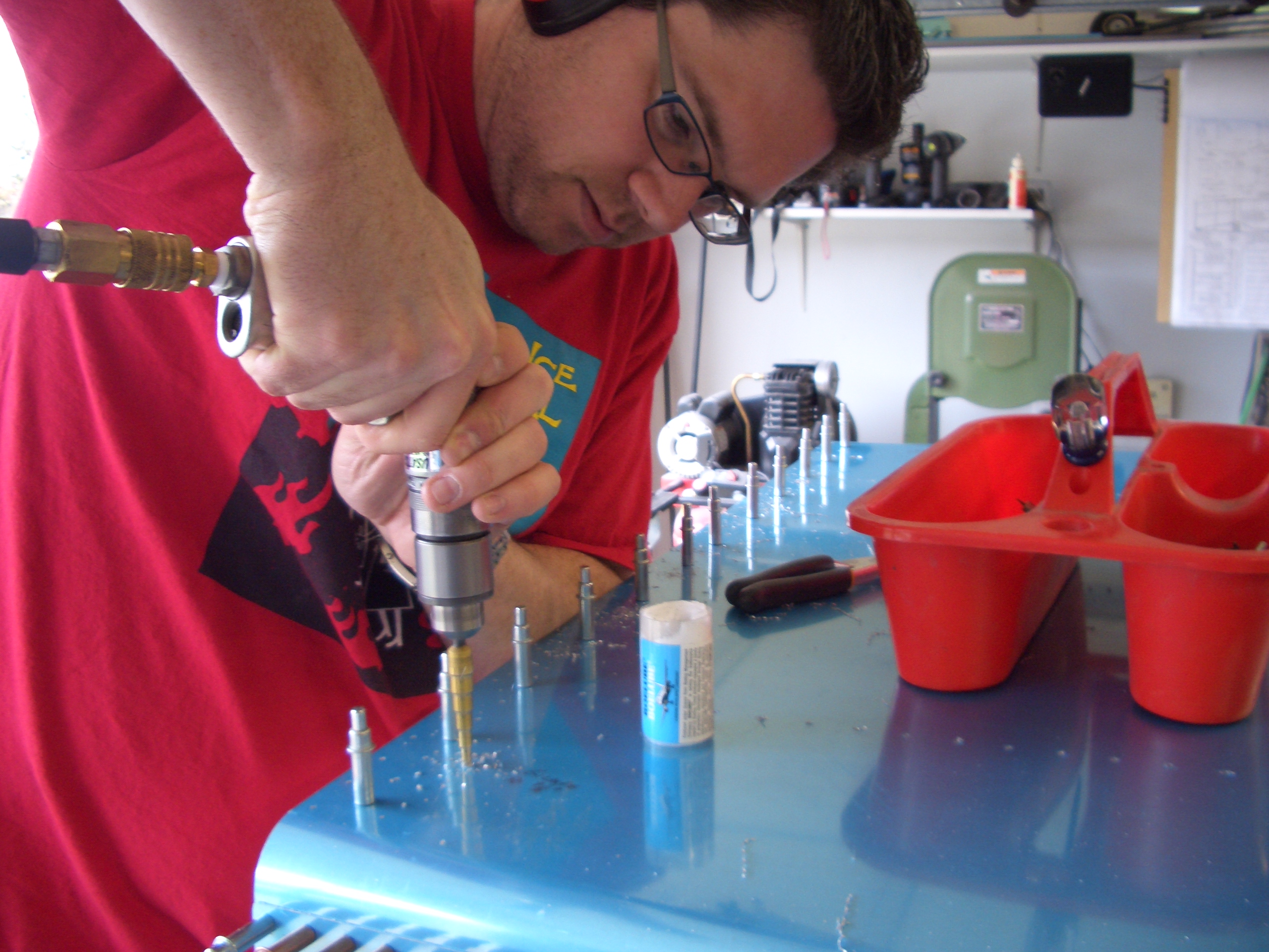
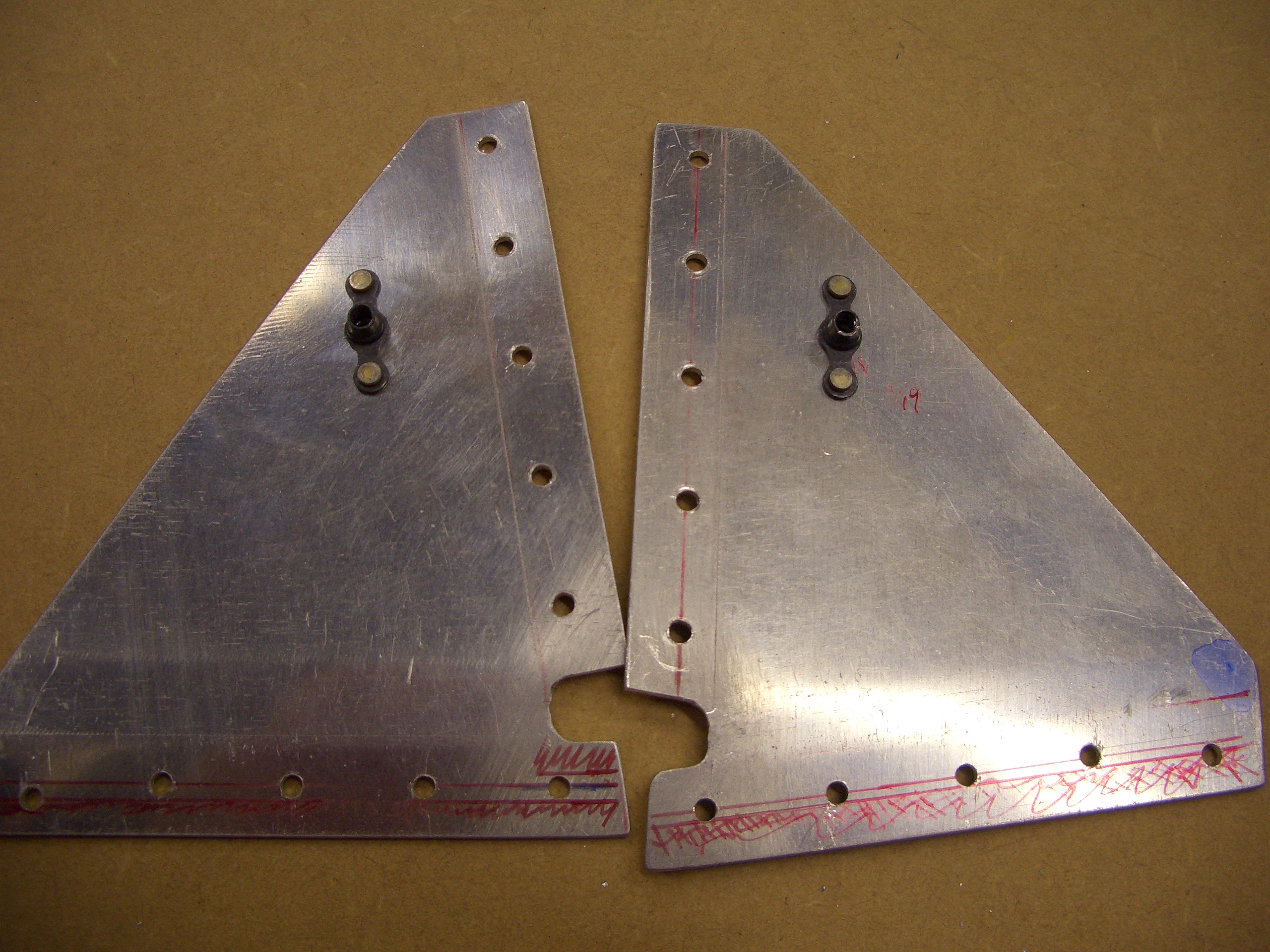
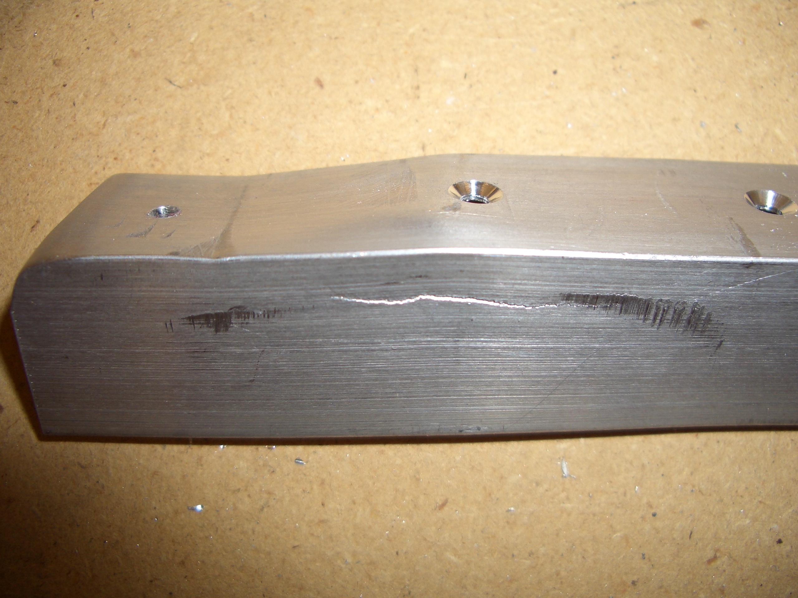
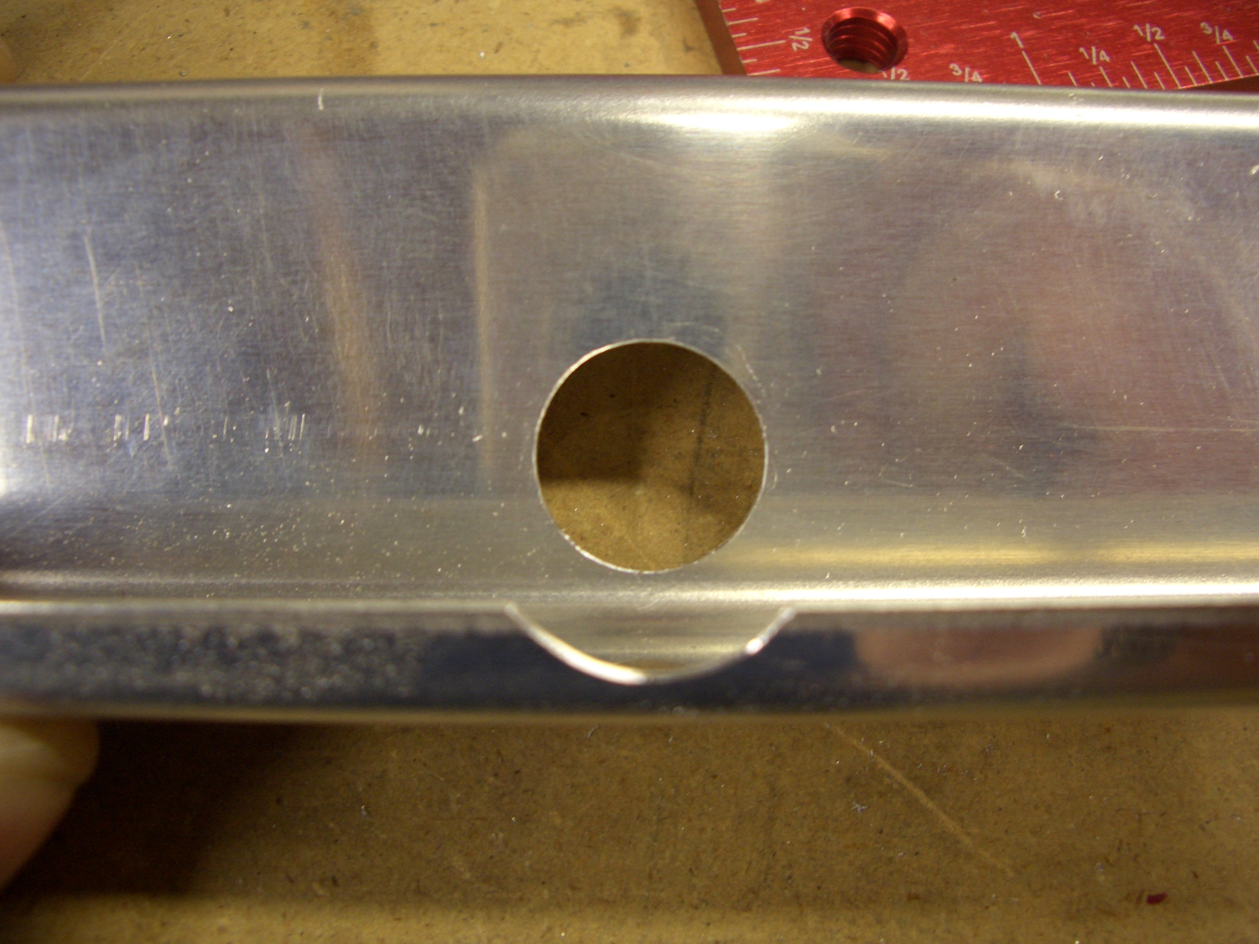
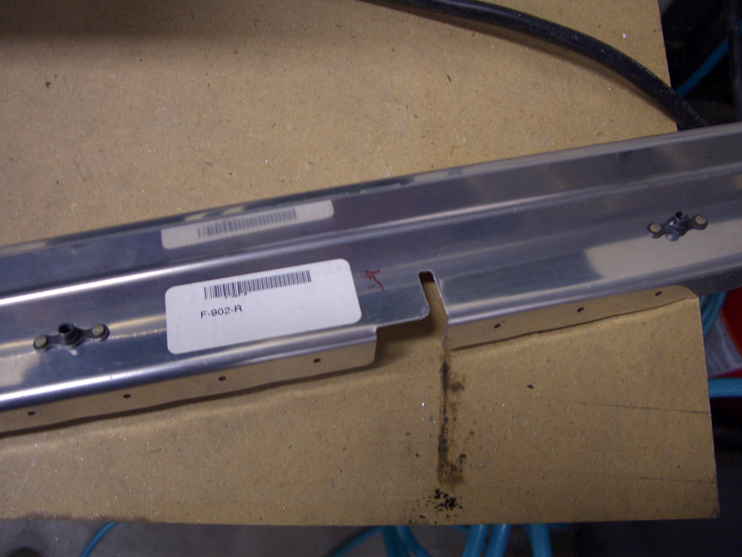
The F-902 bulkheads need some tooling holes enlarged to 5/8″ for the rudder cables.  The aft flange also needs to be relieved so that it won’t interfere with the cable.  I also fluted the outside flange to bring the holes in line.

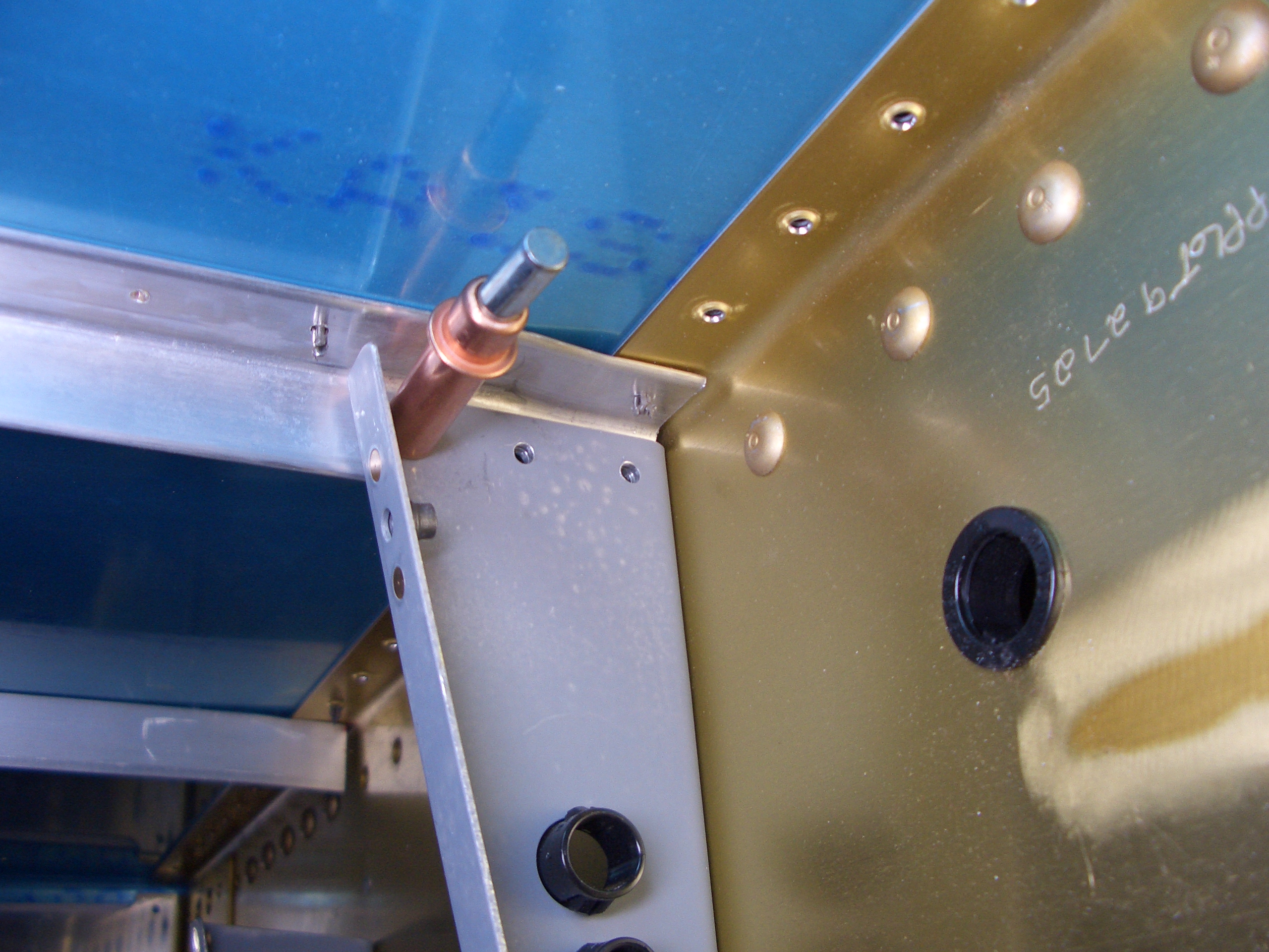
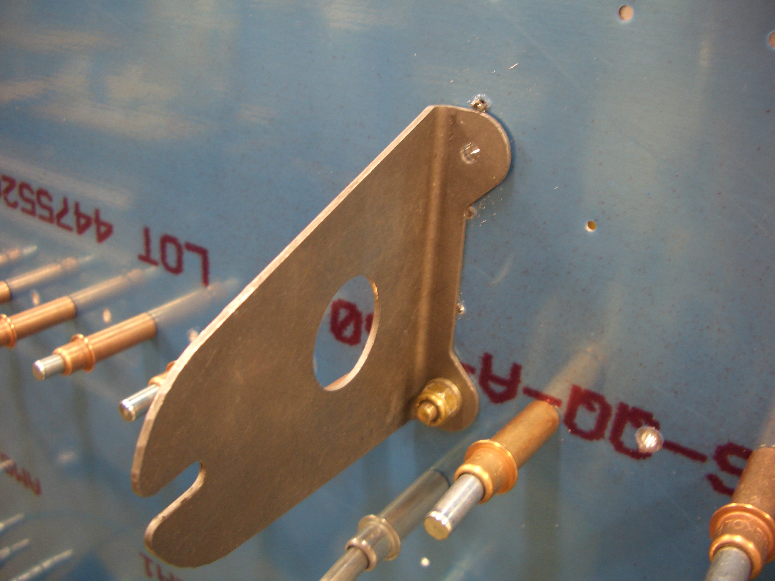
Nutplates are attached to the aft side of the bulkhead so that the fuel vent line can be attached with adel clamps.

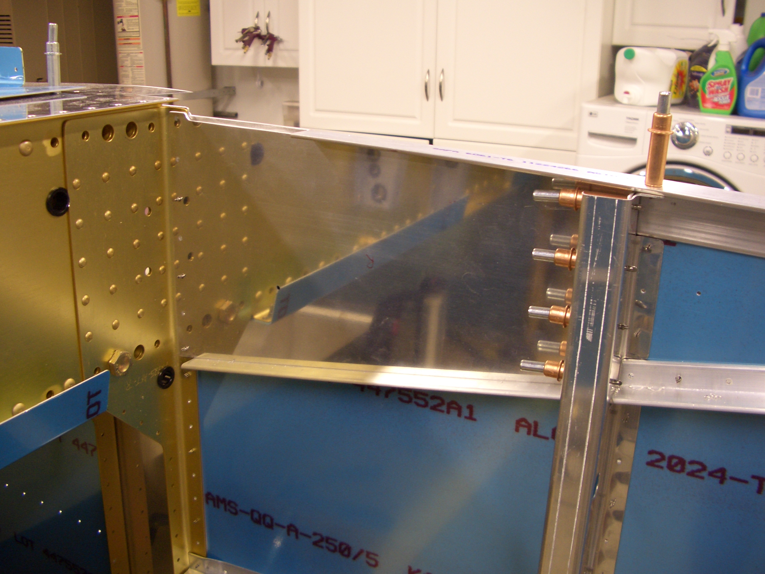
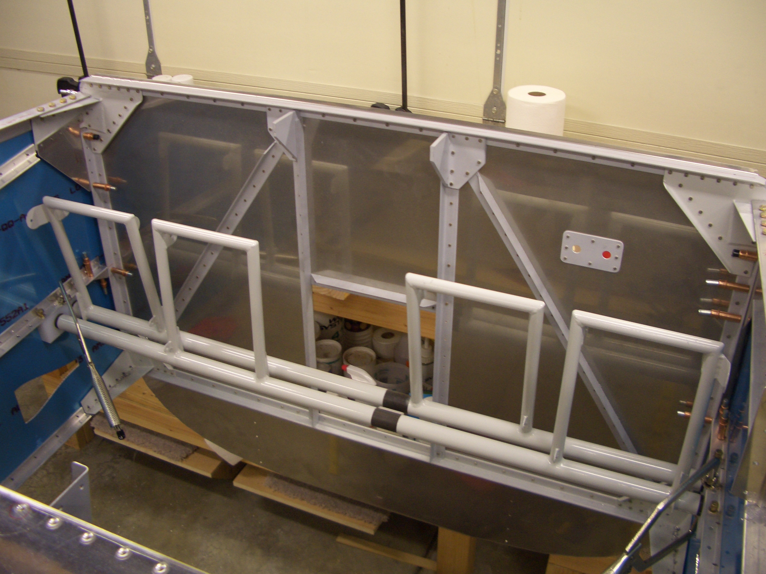
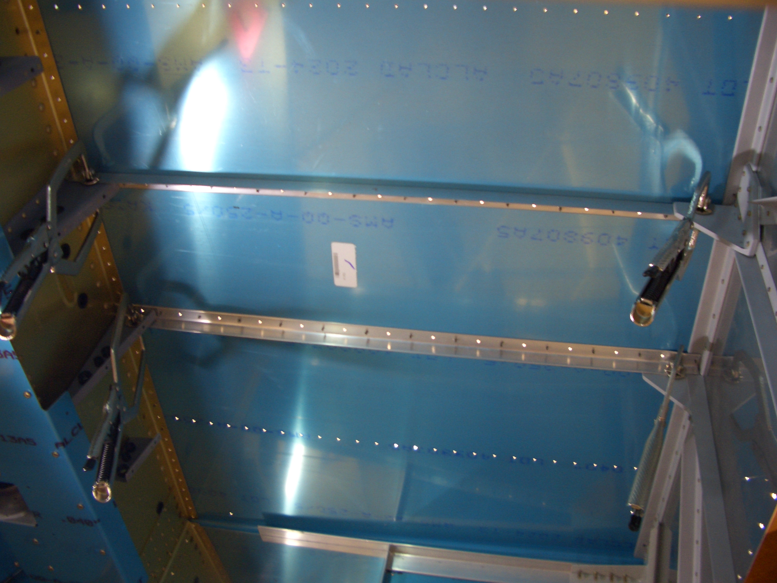
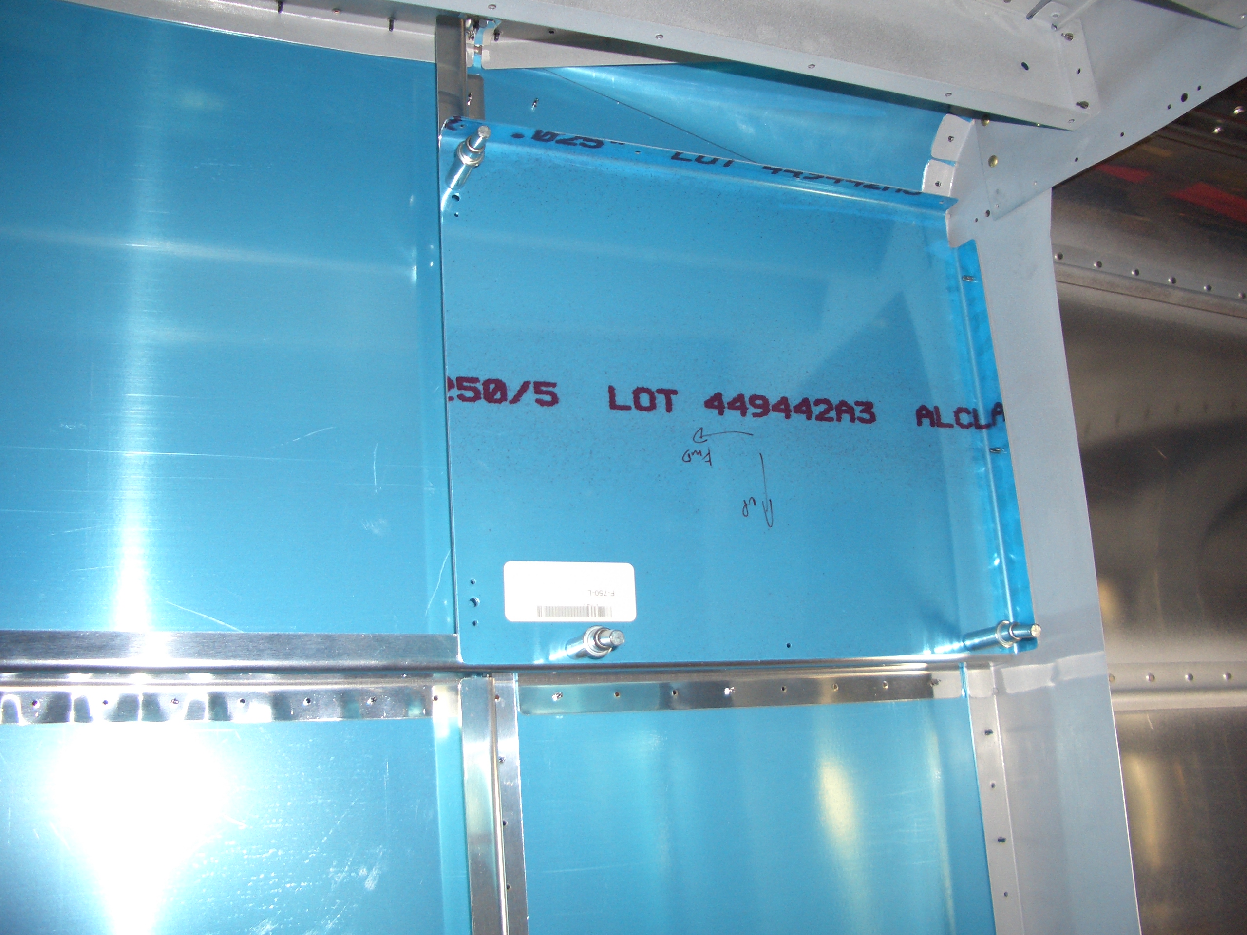
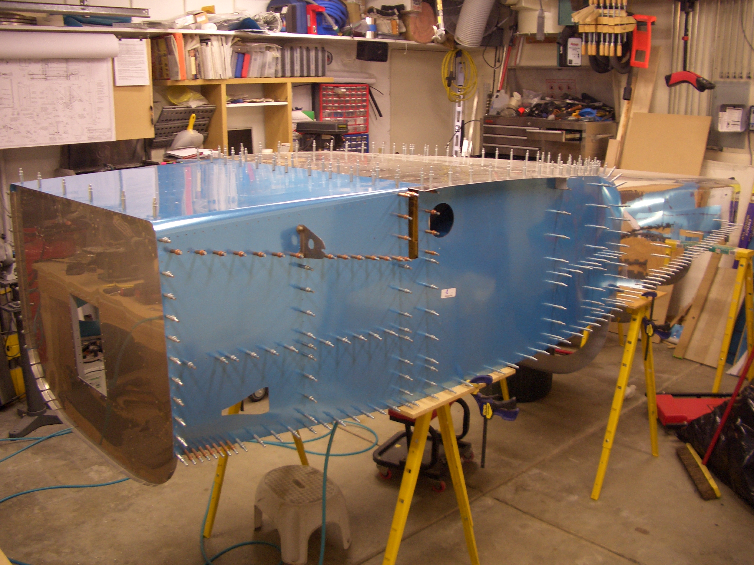
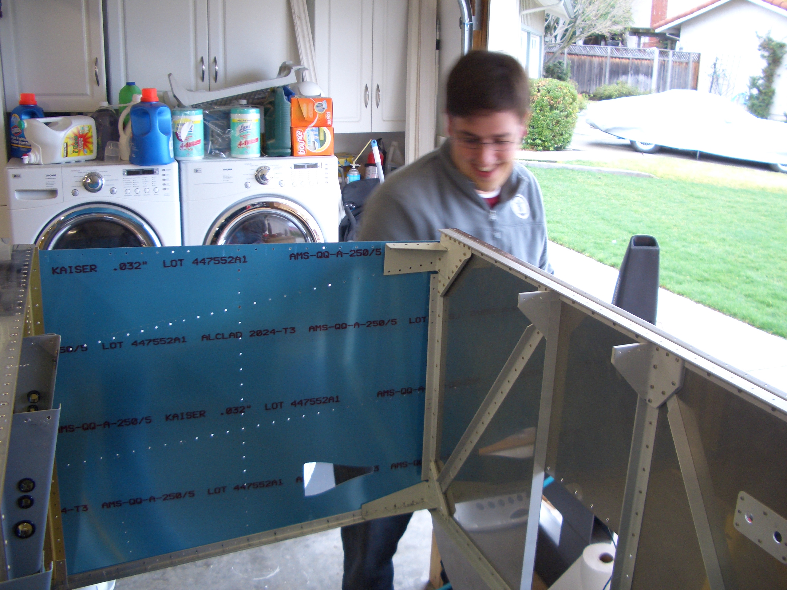
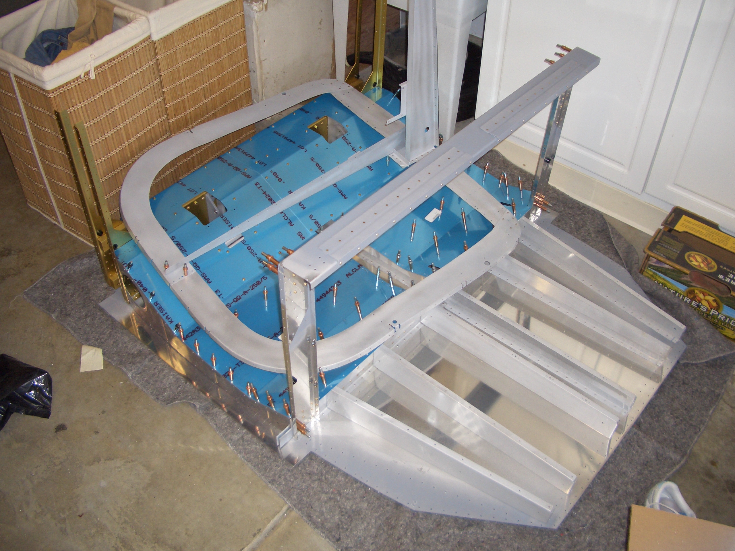
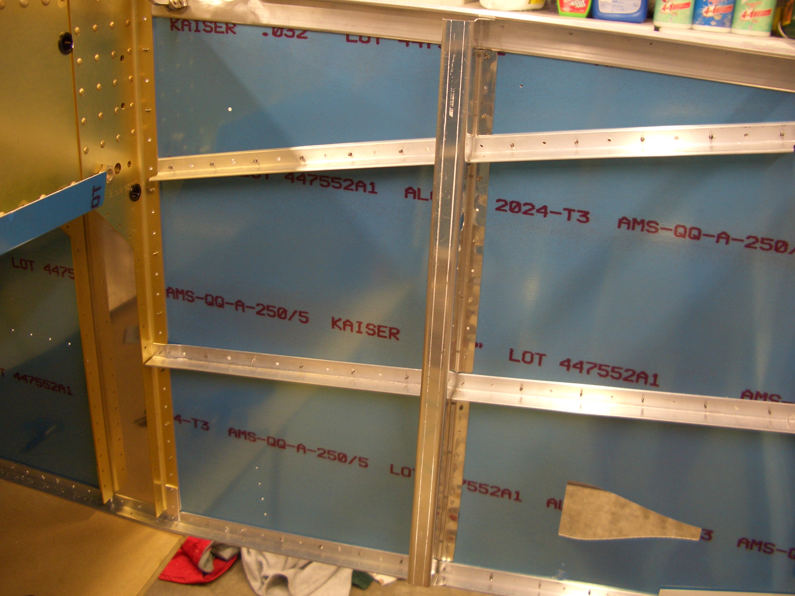
Here is the right side clecoed in place.  Don’t bother at this point, I had to remove it to get the gear attach web in place.

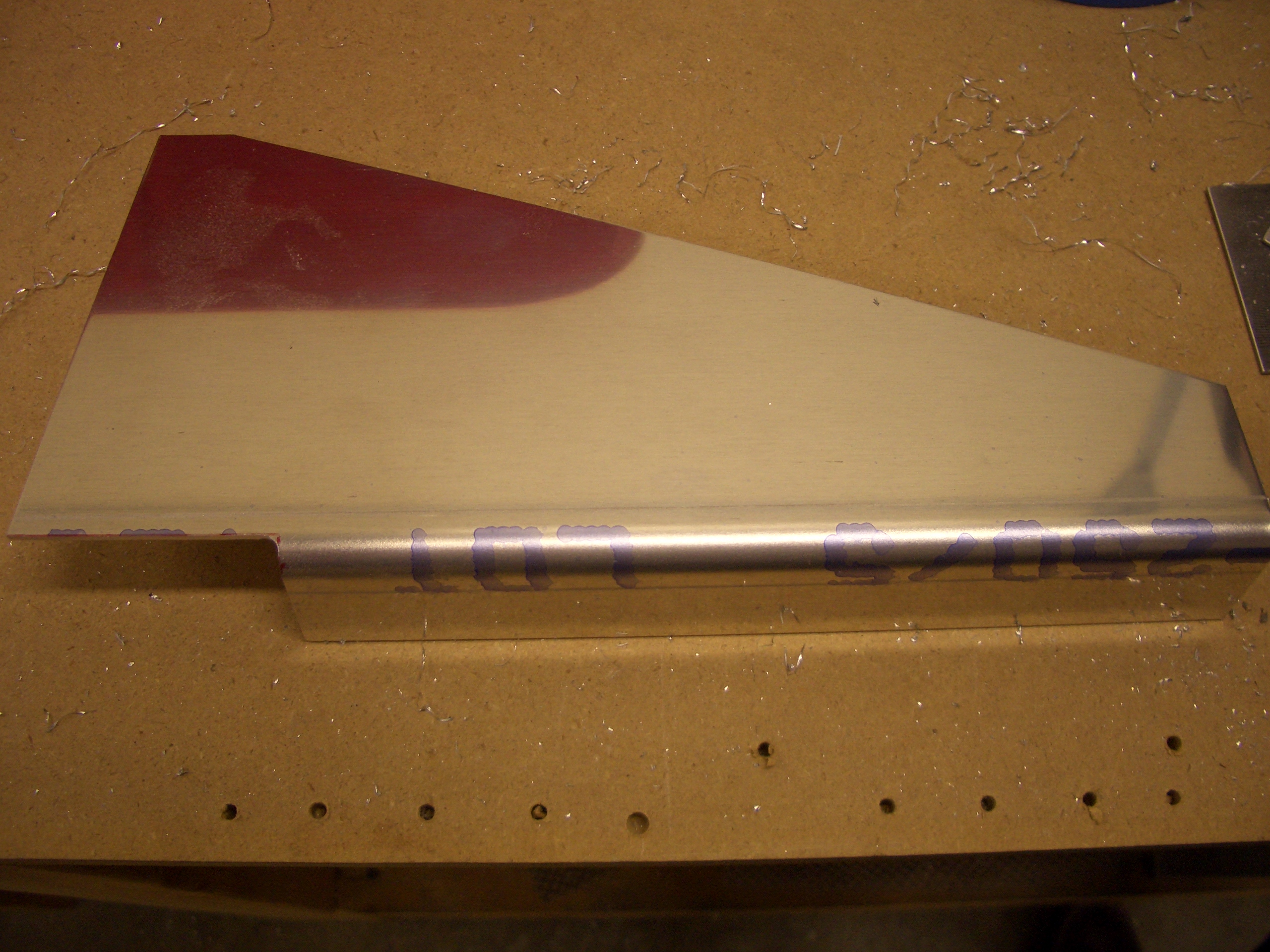
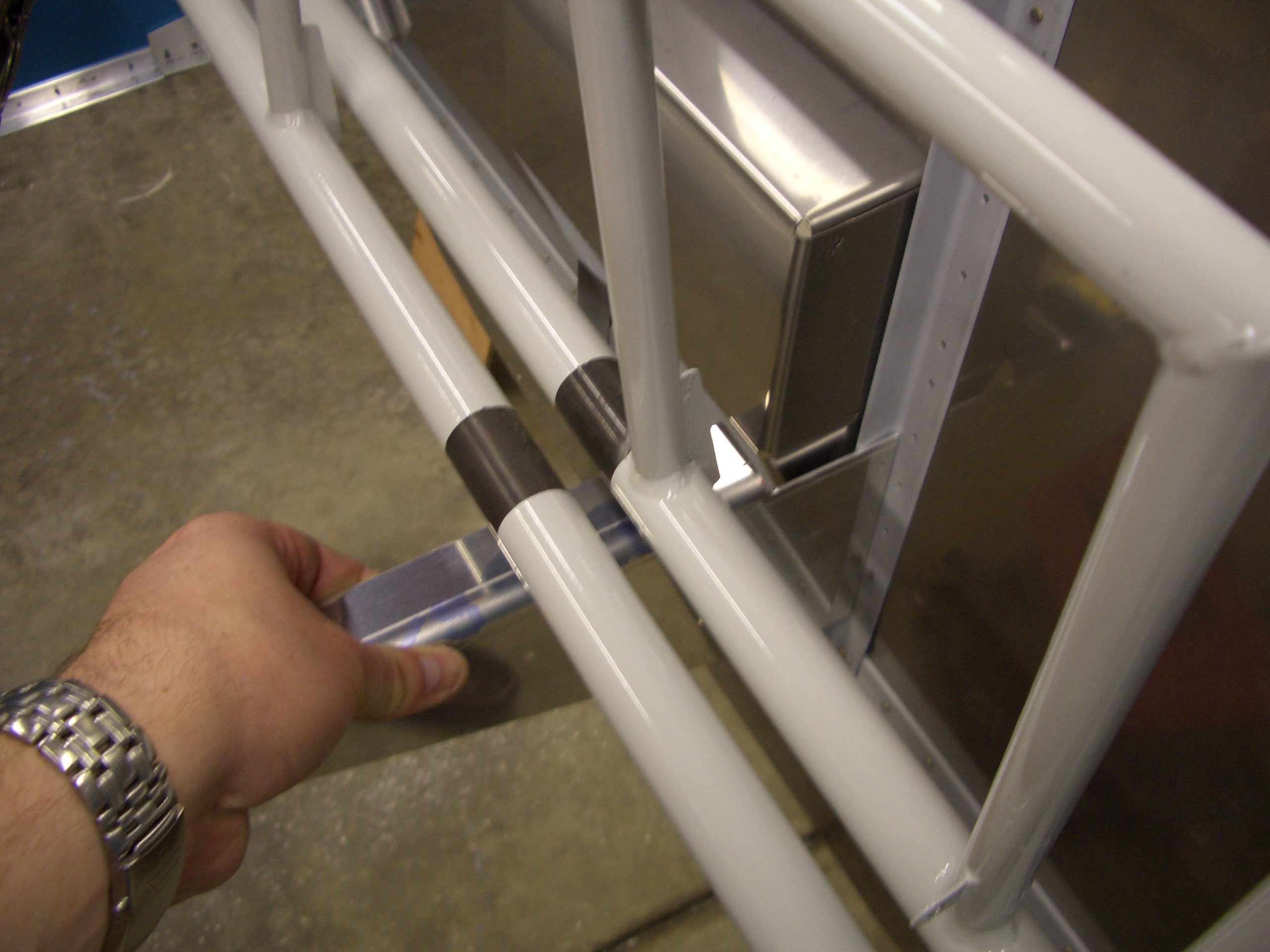
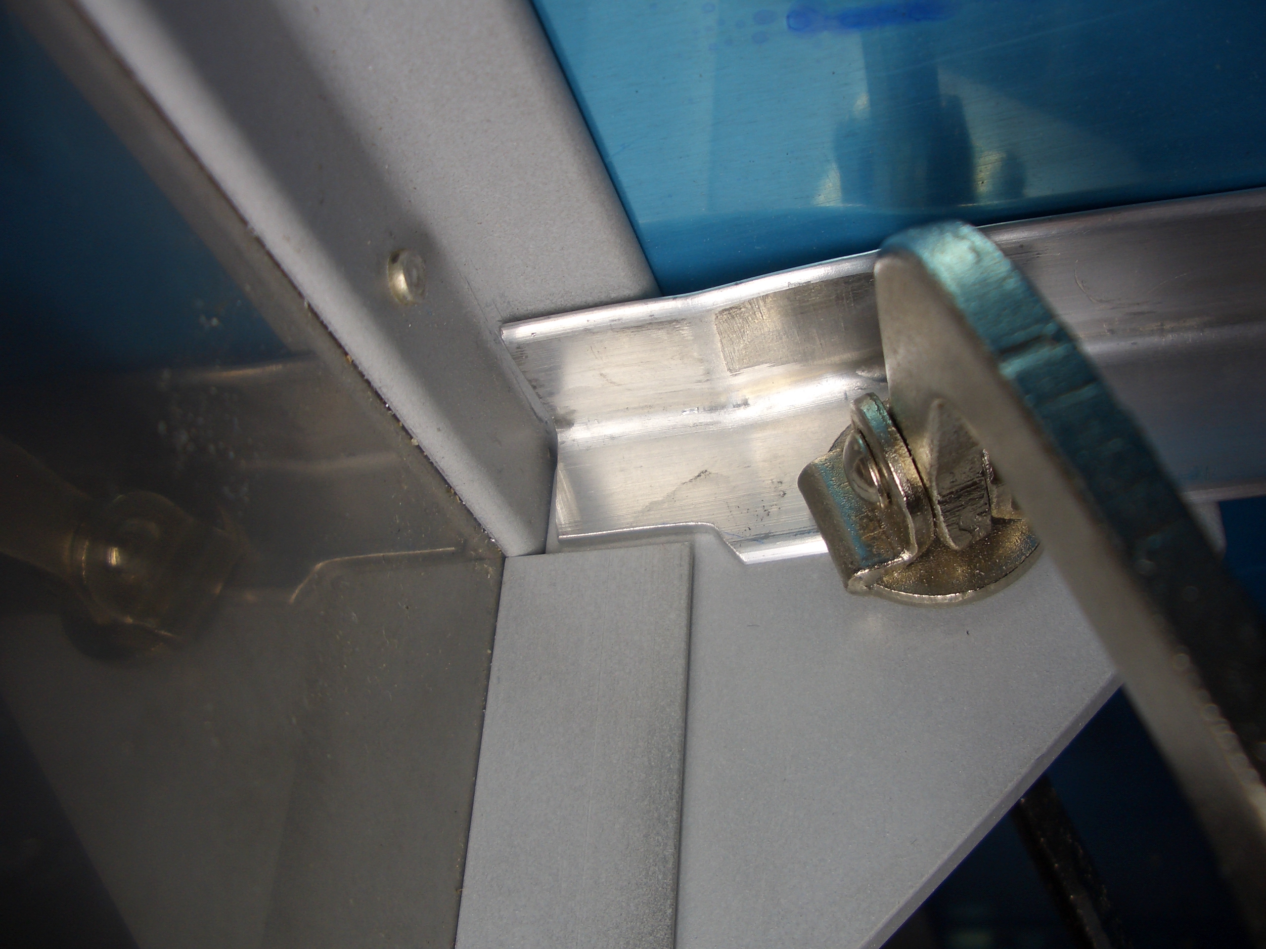
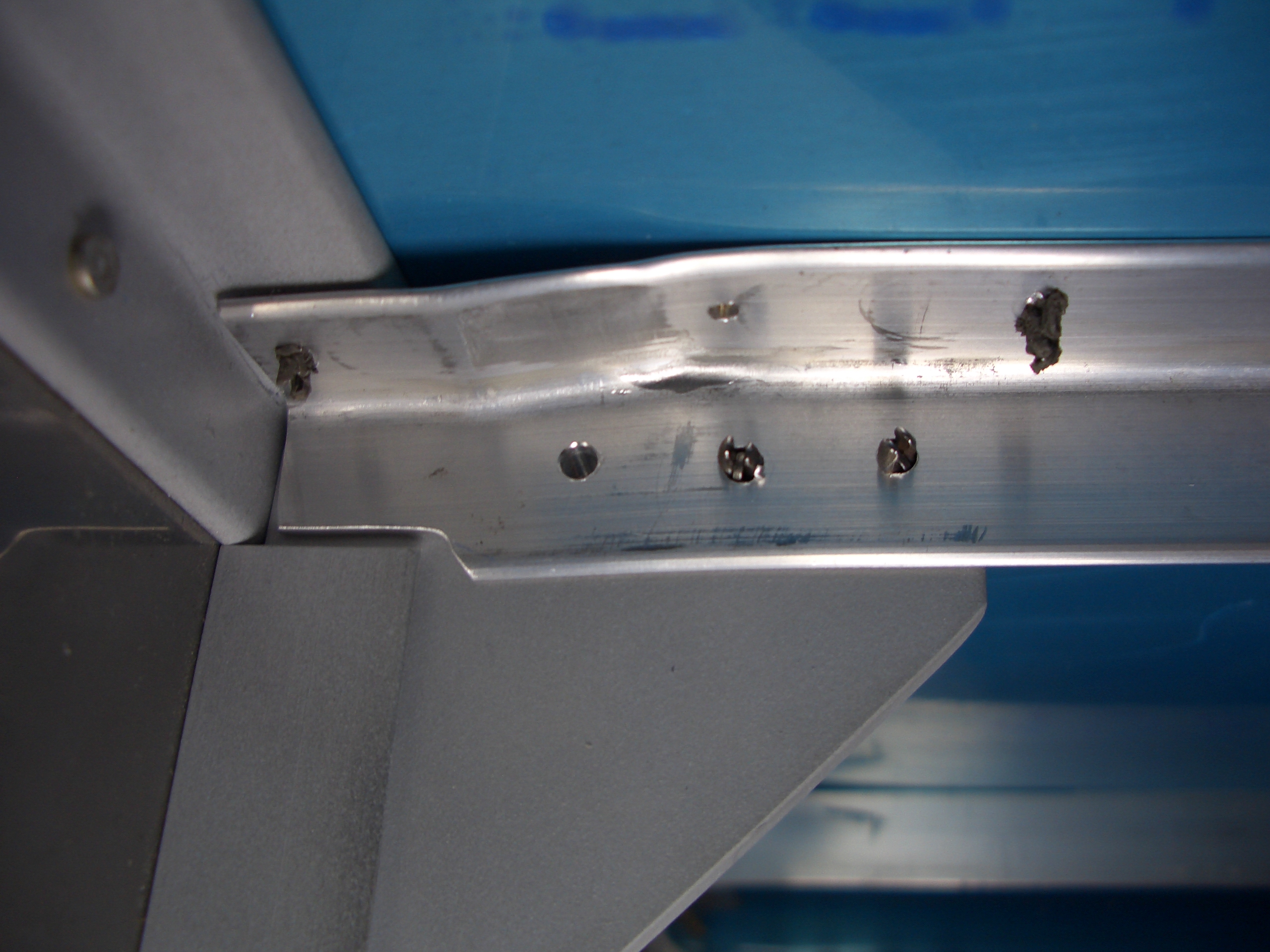
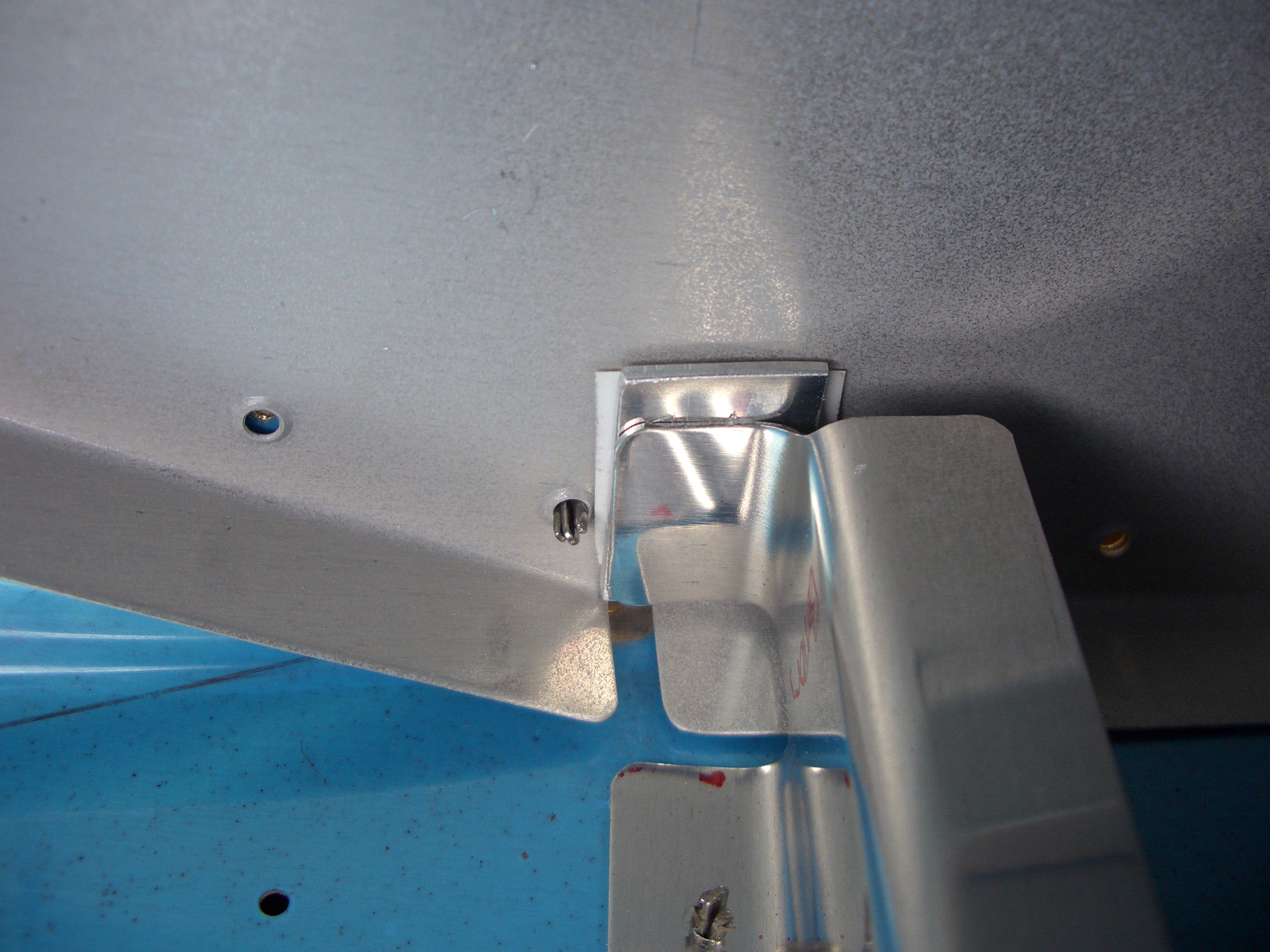
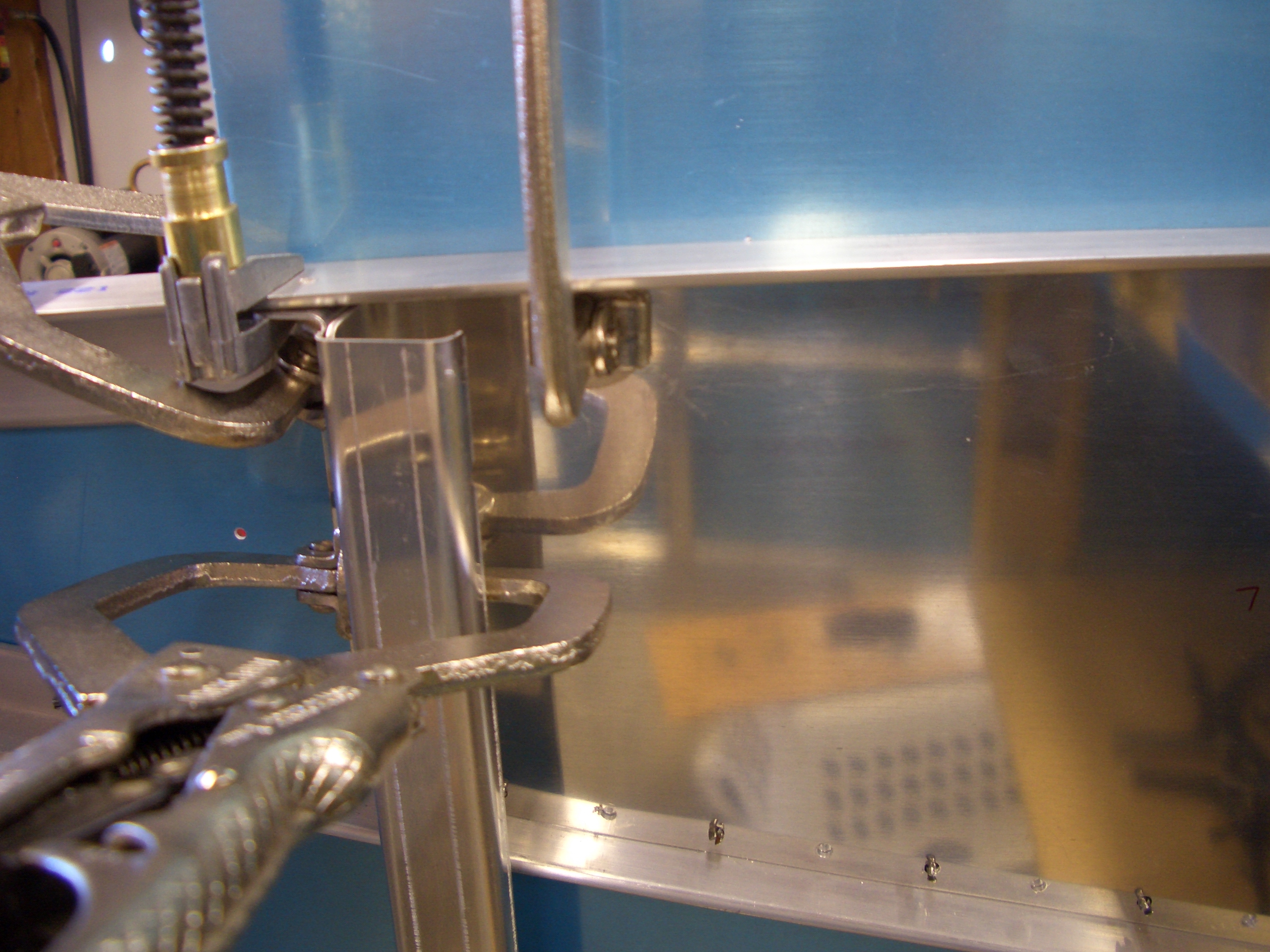
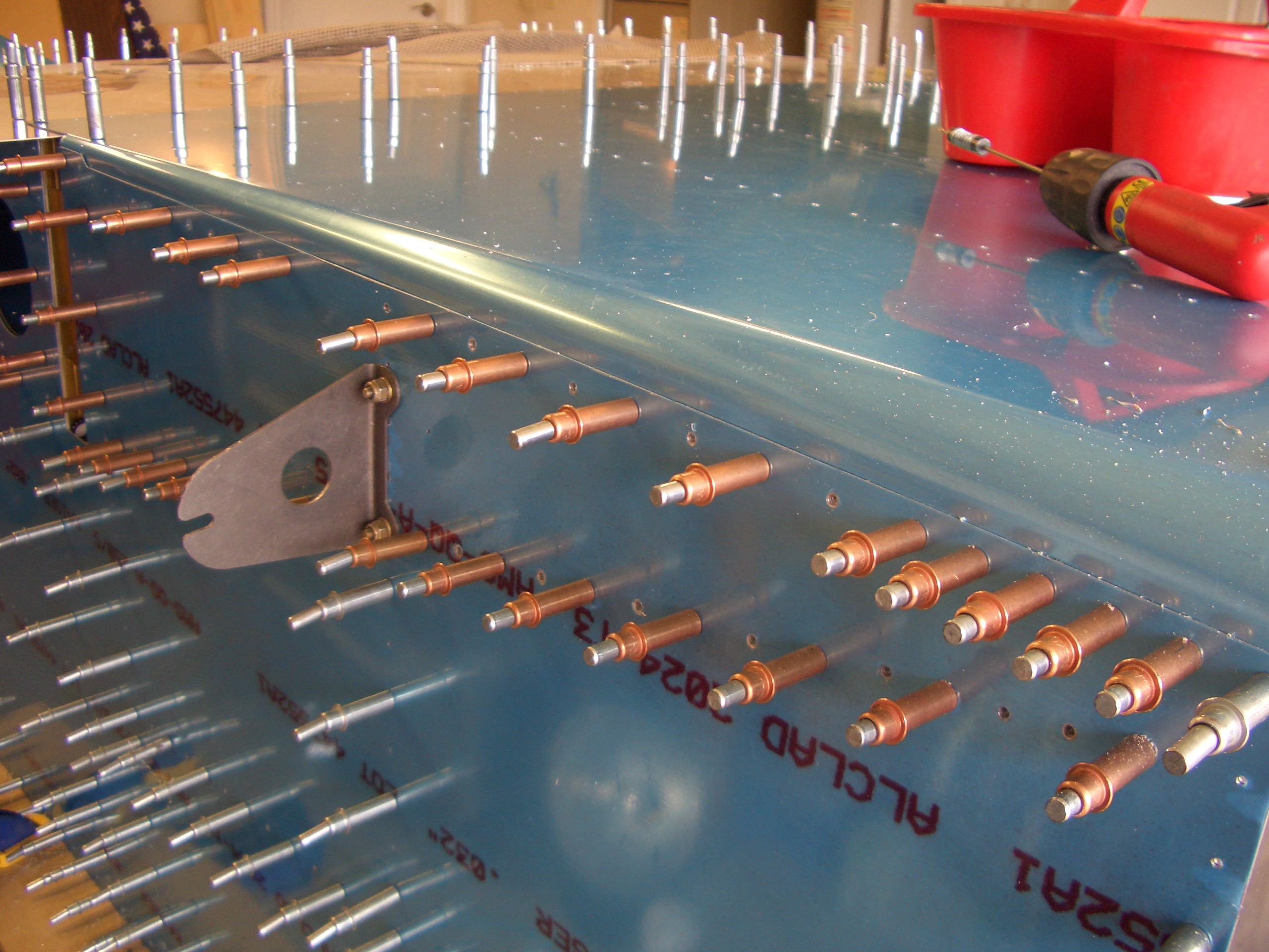
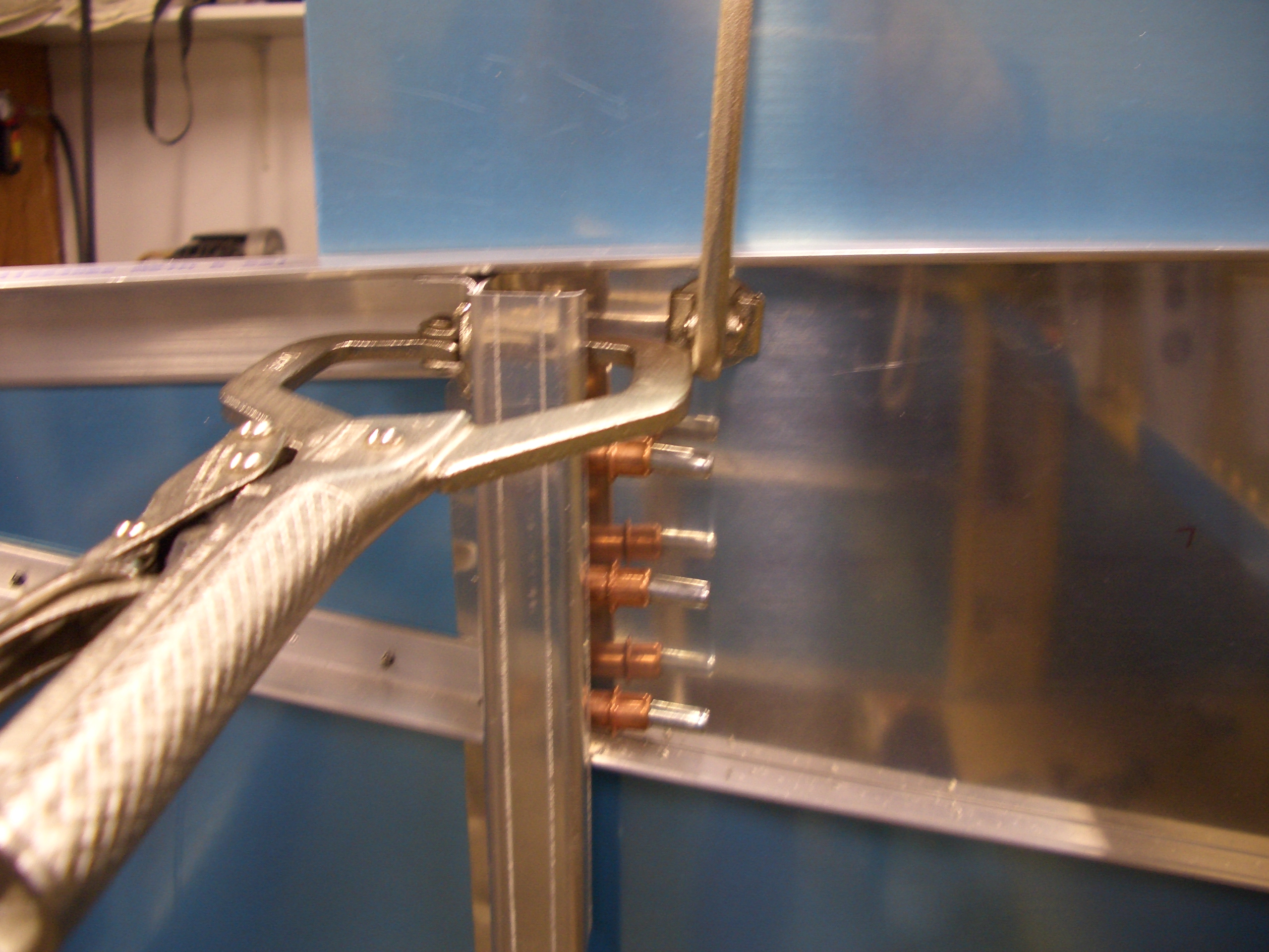
I fit some 0.040″ thick scrap (the blue piece at the top) in place to correctly space the lower longeron away from the side skin.  I then clamped everything tightly together and drilled the gear attach web to the F-902 bulkhead.

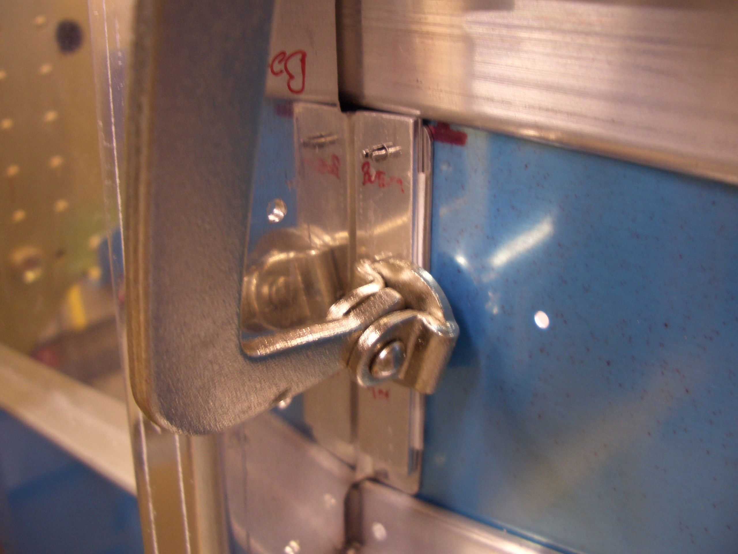
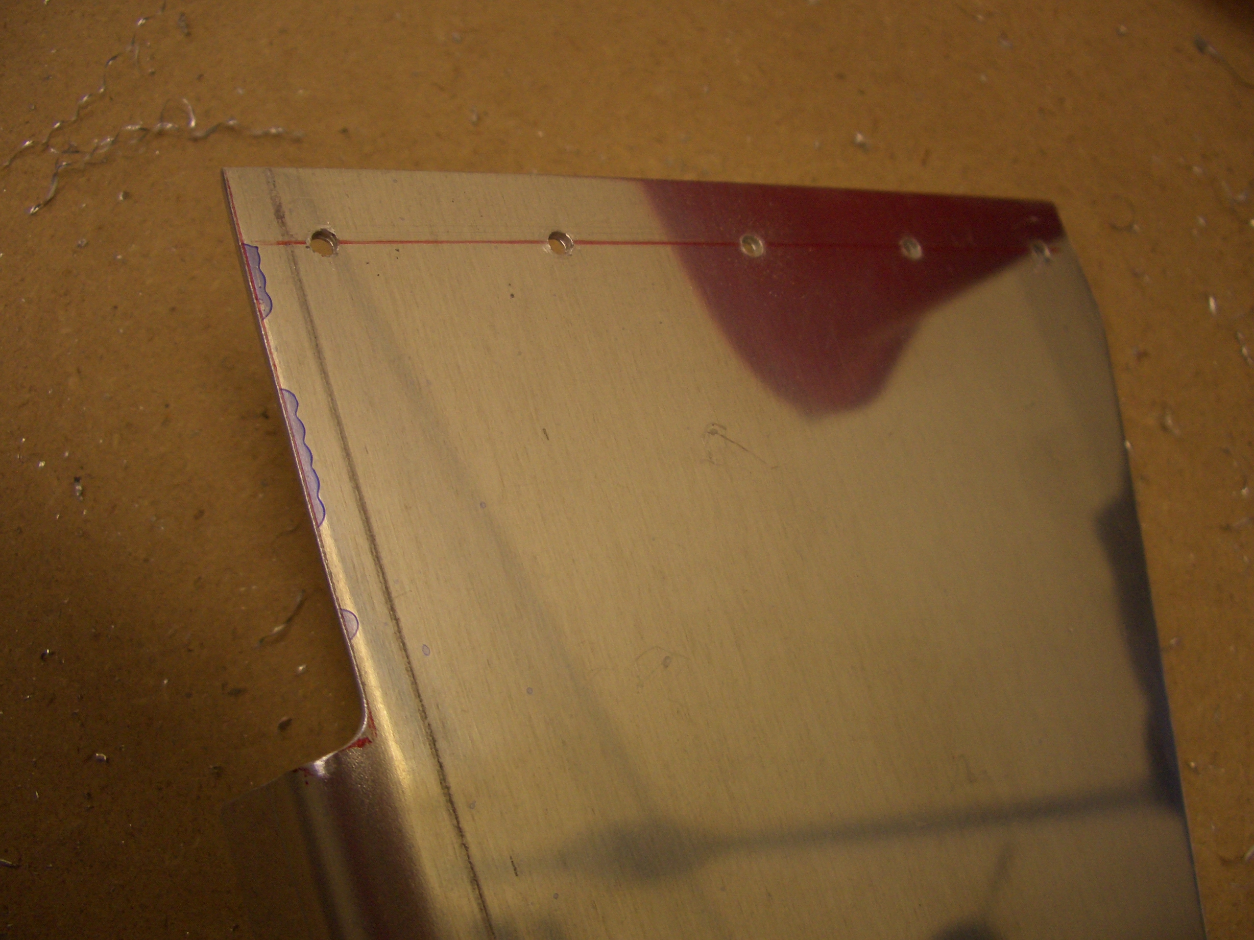
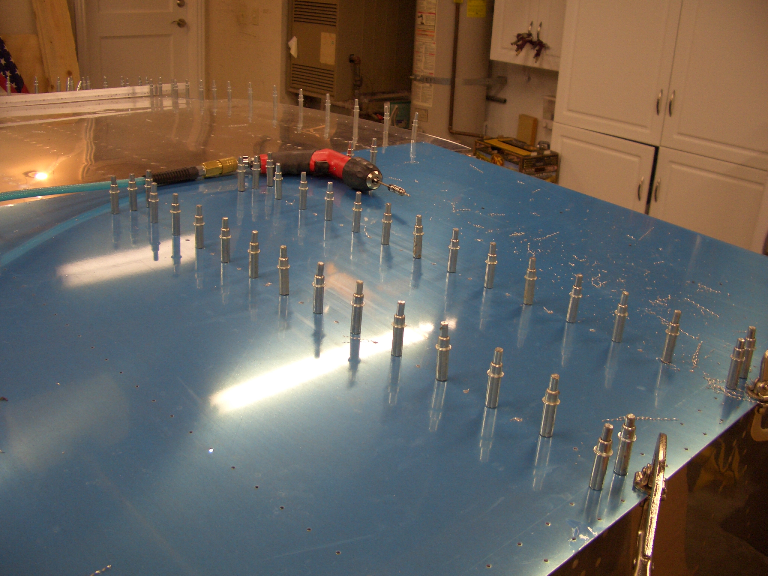
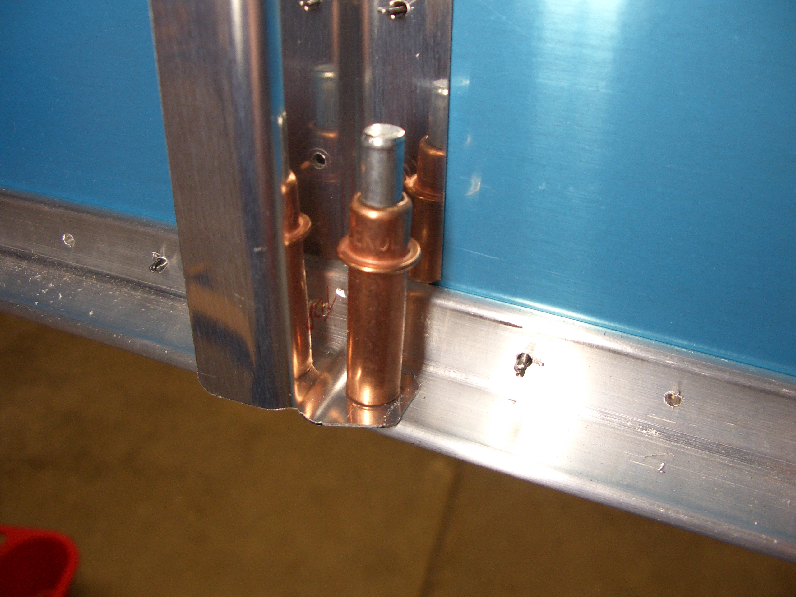
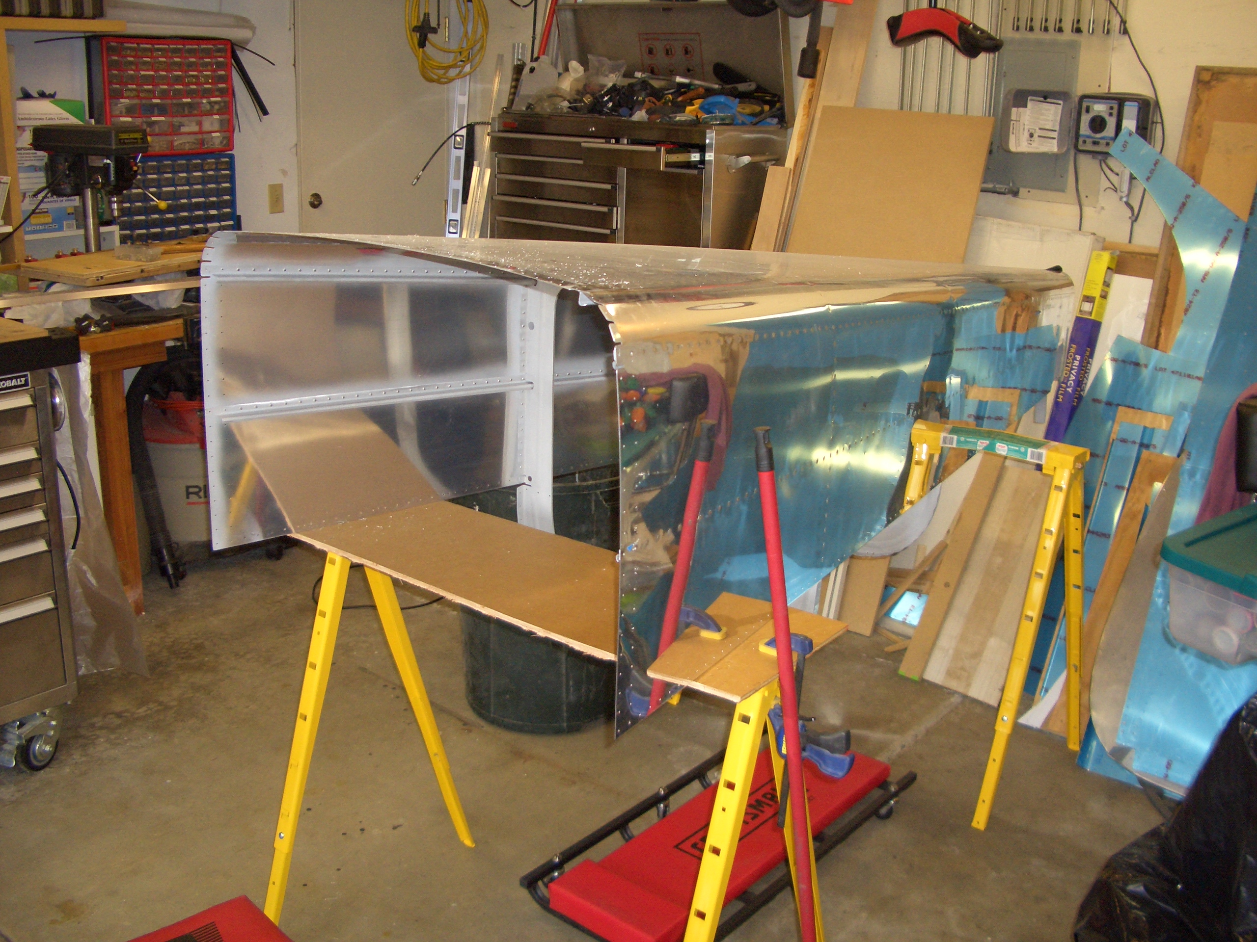
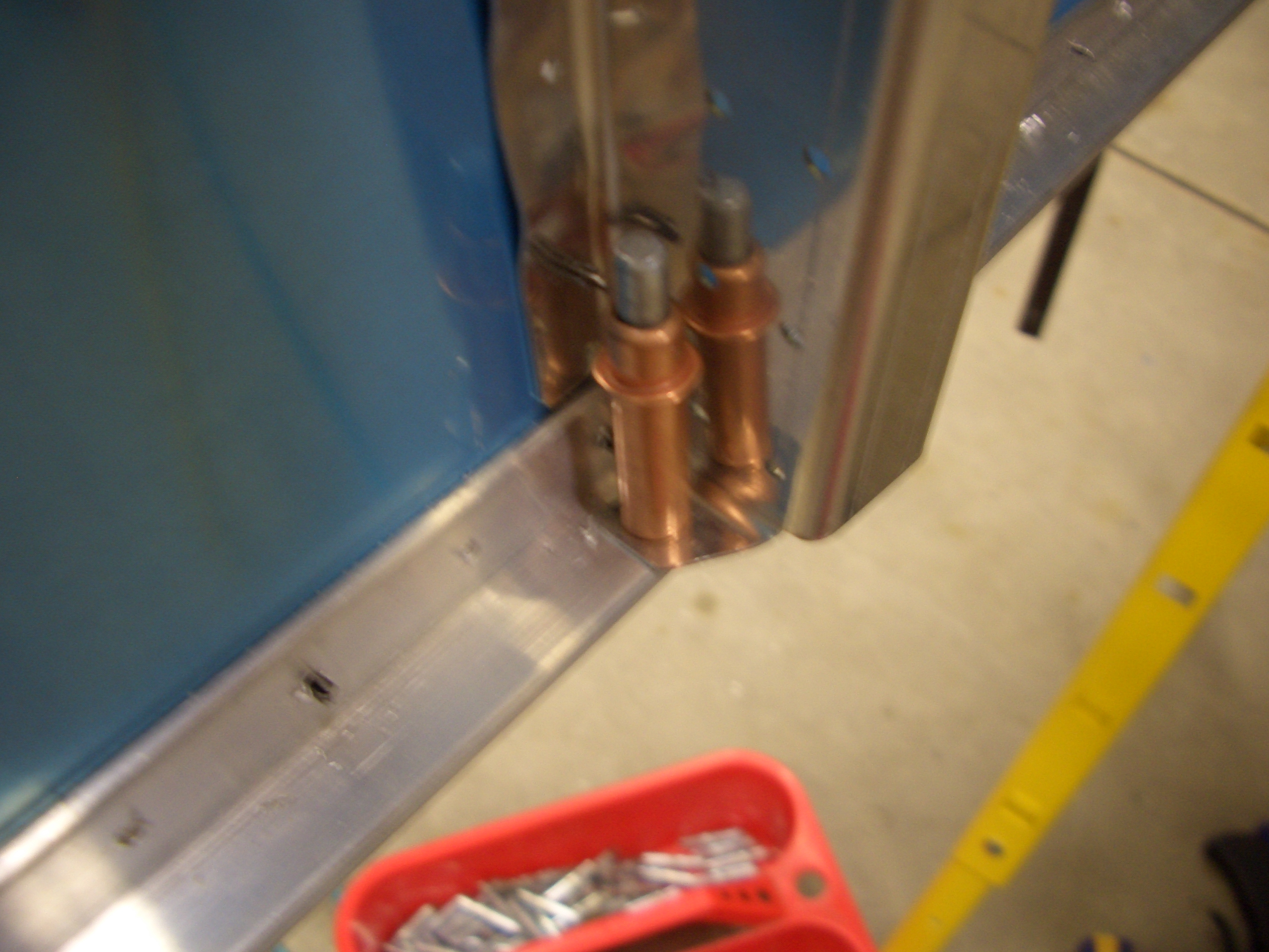
Now that the bulkhead is positioned correctly, the bottom flange can be drilled to the lower longeron.

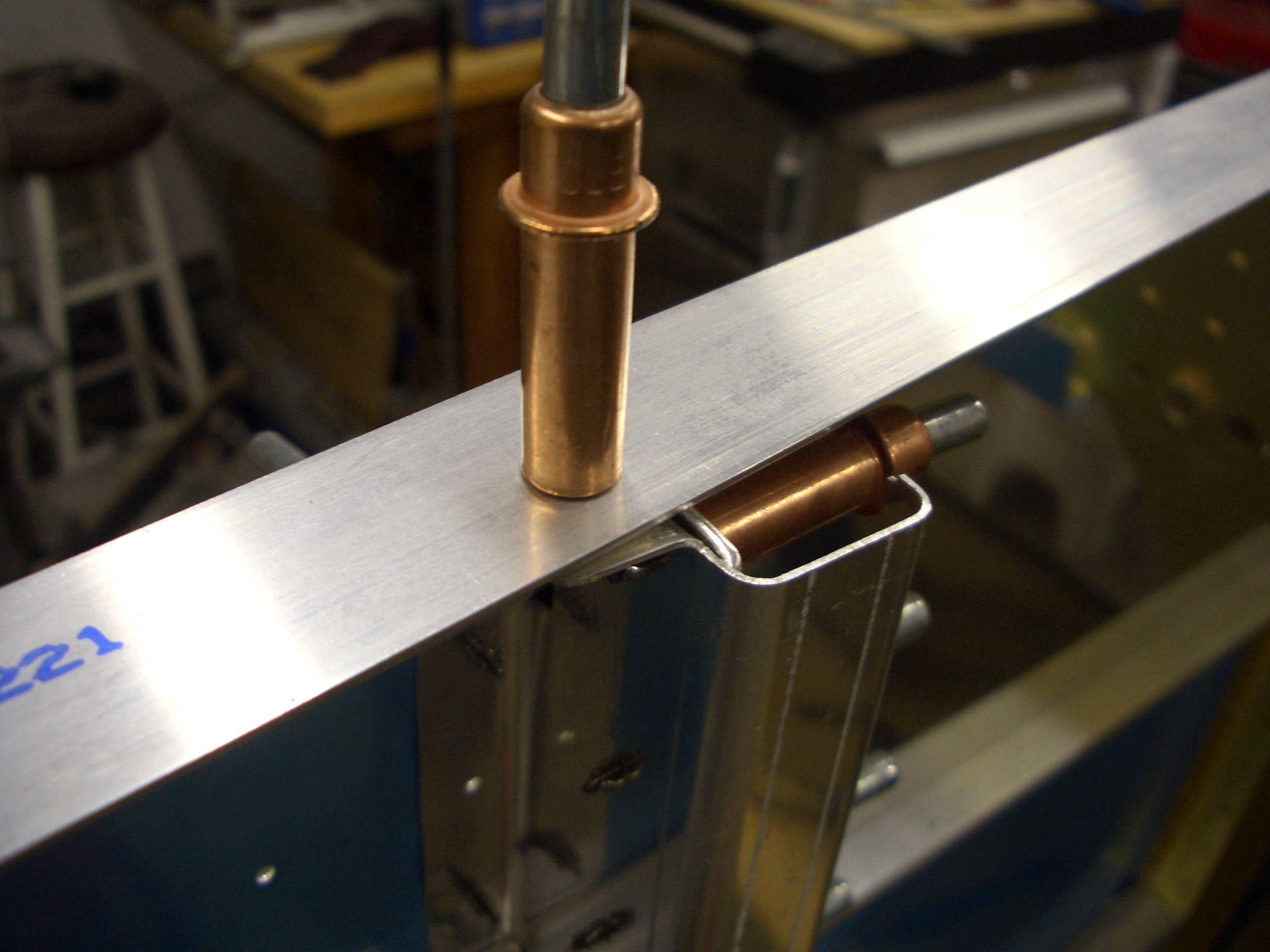
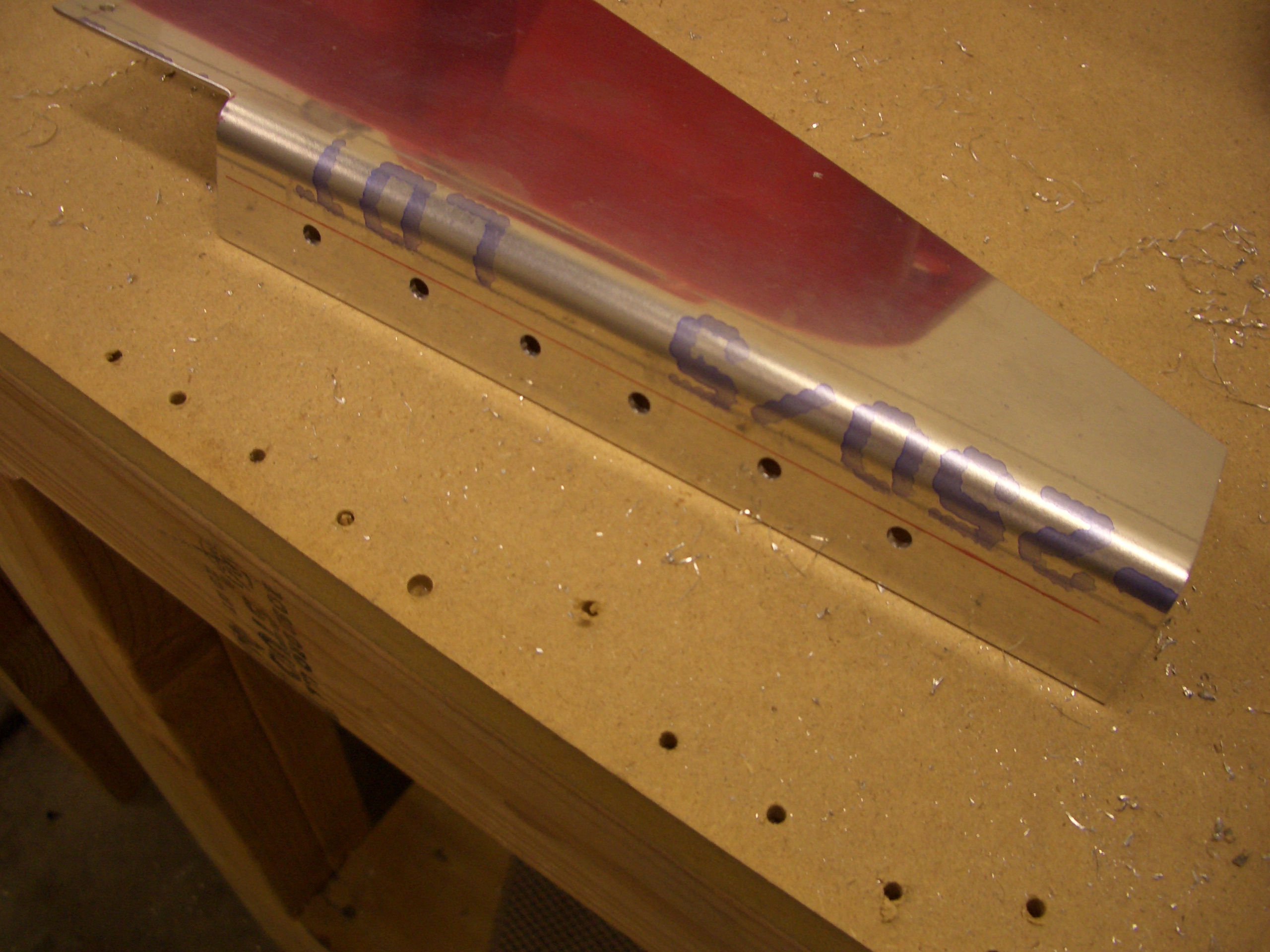
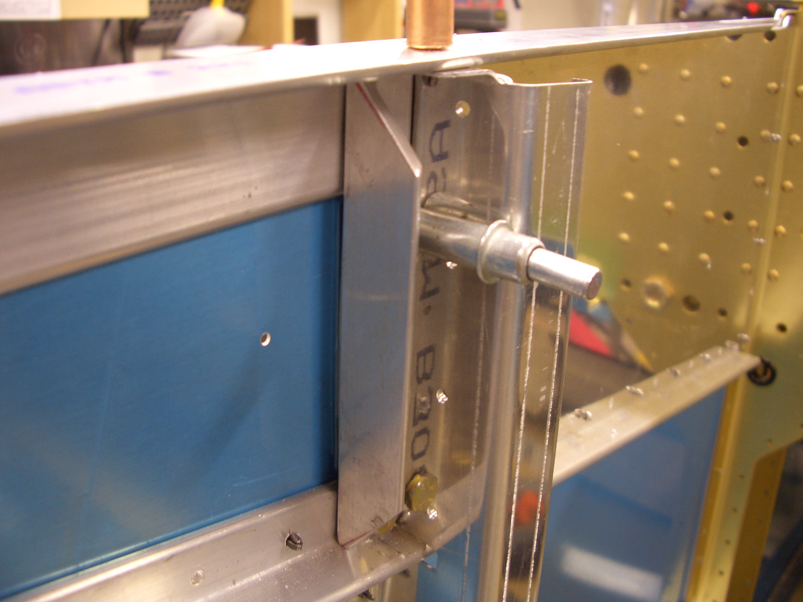
The upper flange can also be drilled to the upper longeron.

I then repeated the steps on the right side.

Assembled Brake Pedals

I started tonight by fabricating the shims that fit between the aux and lower longerons at F-902.  An angle will sit on top of these shims that will serve as the structural support for the forward tank attach bracket.

Unfortunately, when I took the clecos out of the gear web, the holes shifted.  It looks like I didn’t get the gear web fully seated in the aux longeron before match drilling it to the bulkhead.  This side is about 1/16″ off, the other side is about 1/32″ off.  I need to order some things from Van’s anyway, so I’ll go ahead and replace the bulkheads.

I skipped to the next section and began assembling the brake pedals.  I made the optional lightening cuts since every ounce counts.  Instead of the diagonal cuts at the bottom of the pedals, I cut a 1/2″ radius curve to match the radius of the lightening holes in the pedals.  The additional weight savings is negligible obviously, but I think it just looks better.

I drilled the UHMW rudder support blocks for the AN3 bolts that will be used to attach them to the skin stiffeners.  I’ve heard other builders complain about drilling this plastic, but if you turn your drill press down low and feed fairly aggressively (3-4 seconds to drill all the way through), the plastic comes out in one single shaving and the hole is perfectly clean.  You don’t even need to clamp the block (though make sure you hold it down firmly as you back the bit out).

I mounted the rudder tubes to the support blocks.  Make sure you pay attention to the orientation of the blocks.  The holes are not drilled perpendicular to the sides since the skin supports taper inward toward the firewall.

I clamped the rudder bars together with a piece of scrap angle and clamped the brake pedals together using a thick steel rule.  These are not the stock master cylinders that Van’s supplies (which are made by Matco).  These are made by Grove.  They are higher quality than the Matco units and are adjustable.

Drilled Brake Pedals and Mounted Rudder Pedals

I drilled the mounting holes and cut the center rudder support block in half.

Next, I mounted an AN3 bolt in the drill press and filed a point in the tip so that I could mark for the hole in the brake pedals.

The bolt slips through the bottom flange of the master cylinder and is used to scratch a mark in the side bar of the brake pedal.

Then it is a simple matter of finding the center of the hole and drilling for an AN3 bolt.

Then a few washers are used to space the master cylinders away from the brake pedal side bars.  I’m not mounting these permanently now, but I slipped the bolts in to make sure everything moves smoothly with no binding.

Next, I marked for three mounting positions for the rudder pedals.  The plans specify that the support blocks be no closer than 3″ aft of the firewall.  Since I’m tall (6′ 4″), I wanted the option of having the rudder pedals as far forward as possible.  I put marks at 3″, 4 1/16″, and 5 1/8″ which is the dimensions that Dan Checkoway came up with and many have copied.

Here are the holes drilled in the left skin stiffener.  I then repeated the process of the right side.

I then mounted the rudder pedals in the plane in preparation for drilling the center support.  It’s late, so this is a good place to stop.

Fabricated Rudder Pedal Brace

The center rudder pedal brace comes as a roughly shaped piece of thick alclad sheet with a bend along one side.  First a notch needs to be cut out of this flange of the sheet to clear the firewall recess.

I clecoed the firewall recess in place to make sure there is sufficient clearance between it and the rudder pedal brace.

Next, five holes are laid out along the edge that will rivet to the firewall stiffener.

After clamping everything in place and drilling the brace to the firewall stiffener, I put the center bearing block around the rudder tubes and drilled the brace for all three rudder positions.

Now that I’ve determined the aft most position for the pedals, I marked for removing the excess material to lighten the part.  Basically, I left an extra 5/8″ beyond the aft hole and marked a vertical line (the area on the right) and then came up 1″ from the bottom flange and marked a tapering cut from the top left apex to that mark.

After removing the excess material marked above, I cut a series of lightening holes.  The dimension I used were 2 1/4″ for the large hole, 1 1/4″ for the medium hole, and 3/4″ for the small hole.

With that, the rudder and brake pedals are done and can be removed from the plane for the time being.  I’m not going to rivet the brake pedals together now because I’m going to have them anodized along with a couple of other components, and I don’t want to have to pay multiple shop fees for the anodizing.

More Deburring

I haven’t had much time this week due to various projects around the house, but I managed to get a little more work done on the plane tonight.  I deburred a few more of the stiffeners and bulkheads and dimpled the tailcone.  I should be able to spend a fair amount of time this weekend on the project.

Drilled Center Floor Stiffeners

I clecoed the bottom forward skin back on and pulled out the floor stiffeners.  Just like the side skin stiffeners, I had to use my hand squeezer and a couple of scrap pieces of angle to get these to sit flat on both the skin and the angle.  The forward ends of the two center stiffeners also needed small relief cuts to clear one of the firewall stiffeners.

After confirming sufficient edge distance on the skin holes, I match drilled the stiffeners to the skins.

Here is a shot of the inside.  The clamps holding these stiffeners to the beefy angle on the firewall and the cover support ribs on F-704 still need to be drilled.  That will tie all of these structures together quite firmly.

Finished Drilling Floor Stiffeners

I managed to drill the two outboard floor stiffeners by myself.  The problem with these is that there is nothing to clamp them to.  I ended up using some duct tape and a long stick to prop them up against the skin until I could get a hole at each end drilled.  After that it was pretty straightforward.

The two center stiffeners also needed to be drilled to the cover support ribs at the aft end.

And they need to be drilled to the F-601J angles on the front end.  DWG 19 specifies that these should be drilled in assembly with the floor stiffeners, but it would have been much easier if I had laid these out and at least drilled them out to #40 back when I was constructing the firewall.  Oh well, I managed to get it done without too much pain.

Fit Baggage Ribs and Bulkheads

I fit the baggage bulkheads and ribs.  Just like Mike Bullock ran into, I have a gap between the end flange of the baggage bulkhead and the side baggage floor rib.

However, unlike him, my bend wasn’t the cause.  As you can see, the bend ended up perfectly flush with the side skin.  Ignore the gap between the side skin and the bottom skin. That is just due to the dimples that are already in the bottom skin.

Since I didn’t have anything I could adjust to close this gap, I just cut some scrap 0.063″ sheet stock to make a shim.  I intentionally made the shim oversize so that I didn’t have to get it precisely aligned to ensure adequate edge distance.  After removing it, I’ll simply sand down the shim so that it’s no larger than the flange of the side bulkhead.

Ond of the baggage side walls needs to be clecoed in place to ensure the end flanges are positioned correctly before drilling.  I then drilled the bulkhead to the side baggage floor rib.  I ended up with only 1.5d on one of the rivets, but I’ve read that this is a common problem and most have even less edge distance.

I also drilled the other end of the baggage bulkhead to the longeron.  This is another area in which I’ve seen other builders run into edge distance issues, but I ended up with 2d all around.

Fit New Forward Bulkheads

As I mentioned last week, I didn’t properly ensure I had the top edge of the gear web fully nestled inside the aux longeron before drilling the web to the forward bulkhead, so I ended up with significantly misaligned holes.  I could have drilled the holes out for AN3 bolts, but access is tight there because of the reinforcing angle (see picture after this one) and it would have added significant weight.  Anyway, I went ahead and drilled the gear web to the aux longeron (you can see the holes in the lower right of this picture) to keep the web tight against the longeron.  I then match drilled the end flanges to the top and bottom longerons and then match drilled it to the gear web.

I finished fabricating the reinforcing angles where the forward tank attach bracket mounts.

I drilled the upper hole (lower in this picture) to #15 and then reamed to 3/16″, then bolted the tank attach angle in place to drill the second hole through the skin, bulkhead, spacers, and angle.

Unfortunately, while drilling the second bracket, my #15 bit broke right as I finished the hole.  Fortunately, the bit wasn’t jammed in the hole and came out easily.

I then bolted both brackets on with some scrap hardware to keep the reinforcing angle precisely in position for the final hole that needs to be drilled out countersunk for a screw.  I’ll do that after the bottom skin is on though.

All of the fabrication work for the forward fuselage is done.  I still need to match drill all of the skins and take care of a laundry list of small tasks, then this can all come apart for deburring, countersinking/dimpling, and priming.

Disassembled Fuselage

I got started today by finishing up the remaining drilling that needed to be done before disassembling the fuselage.  First up is to match drill the outboard seat ribs to the side skins.

I also drilled the lower longeron to the side and bottom skins as well as the gear web and lower engine mount.

Two holes on the bottom skin just aft of the firewall need to be enlarged to 7/16″ for the fuel vents.

Andre took a picture of me drilling the other one.

After drilling the side skins to all of the various bulkheads and drilling the center section bottom skin to the tailcone, we started disassembly.

Here’s the growing pile of parts from the disassembly.  My cleco tote is overflowing with clecos again.

Finally, we separated the center section from the tailcone.

The tailcone is all that is left on the sawhorses.

I next started working my way through a small list of tasks left to complete before priming.  Here, I’ve riveted K1000-08 nutplates to the outboard side of the lower engine mount gussets.  These will be used to anchor the vent line.

While deburring one of the skin stiffeners, I noticed this crack.  I’ll call Van’s tomorrow and get another one sent.  Hopefully, I can just use this one to match drill the new one so that I don’t have to reassemble the fuselage to drill it.

Here’s a shot from a slightly different angle.  The crack goes all the way through and is visible from the inside as well.

I made it through a good chunk of the small parts before calling it a night.  All of the pieces on the left are deburred and dimpled/countersunk.  I should be able to get through the remaining pieces on the right in one more session.  I’ll still have the longerons to countersink (over 400 holes), and a number of holes in the tailcone and center section to debur/dimple.