No pictures tonight as it would look just like last night. I drilled all of the holes in the tailcone that needed to be drilled right now. This included the stringers and bulkheads (except for the frontmost one (F-706) and the top row of holes where the longerons are attached. Drilling the bottom was a pain because I had to lie on a creeper and was absolutely covered with aluminum shavings by the time I was done (wear a full face mask if you want to keep them out of your eyes).
Finished Aft Fuselage Fabrication
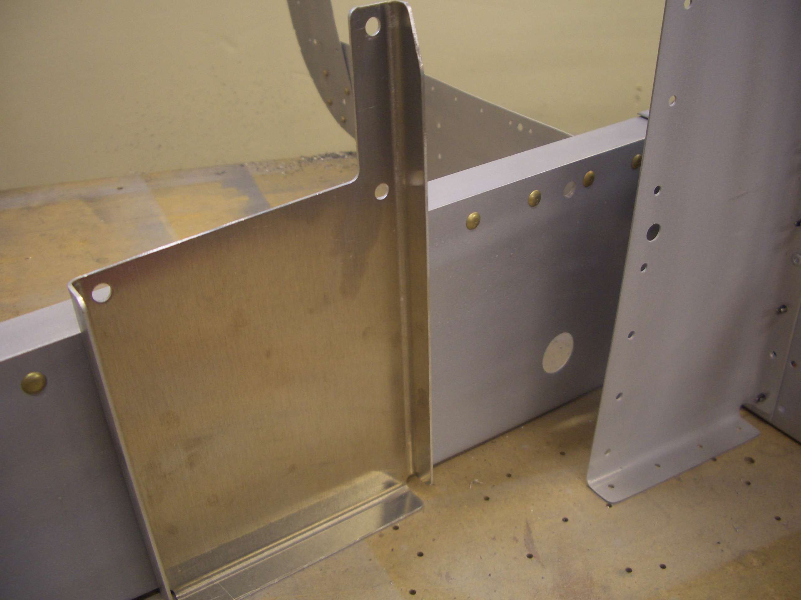
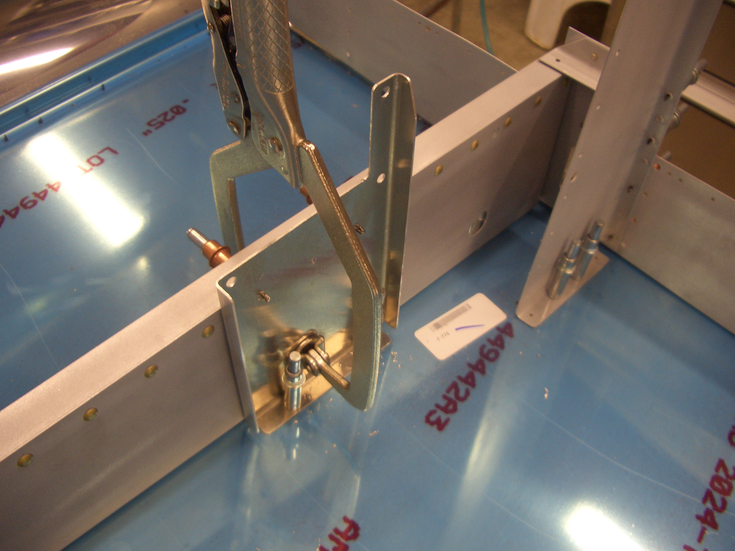
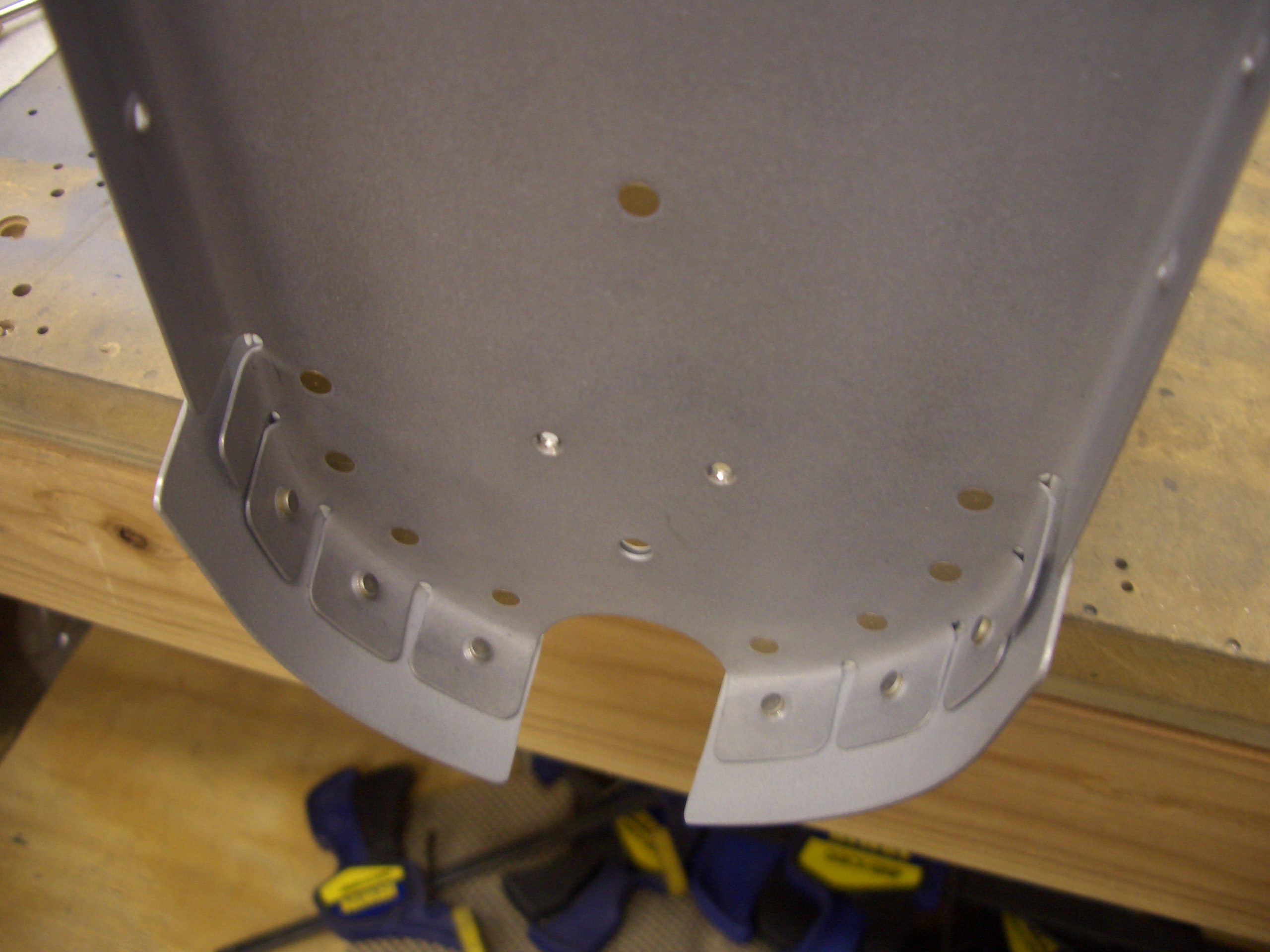
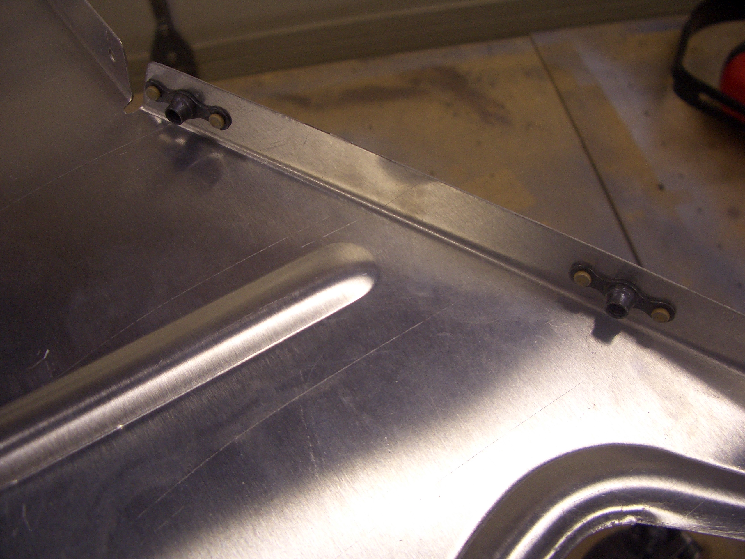
I had a couple of tasks to take care of before disassembling the aft fuselage. First up is to mount the autopilot pitch servo mounting bracket. The forward edge of this has to be 3.43″ from the center of the 1/4″ pivot hole for the elevator bellcrank. This required drilling out three rivets so the mounting plate could sit flush. If you’re installing a dynon autopilot, just leave these rivets out from the beginning and save yourself the time.
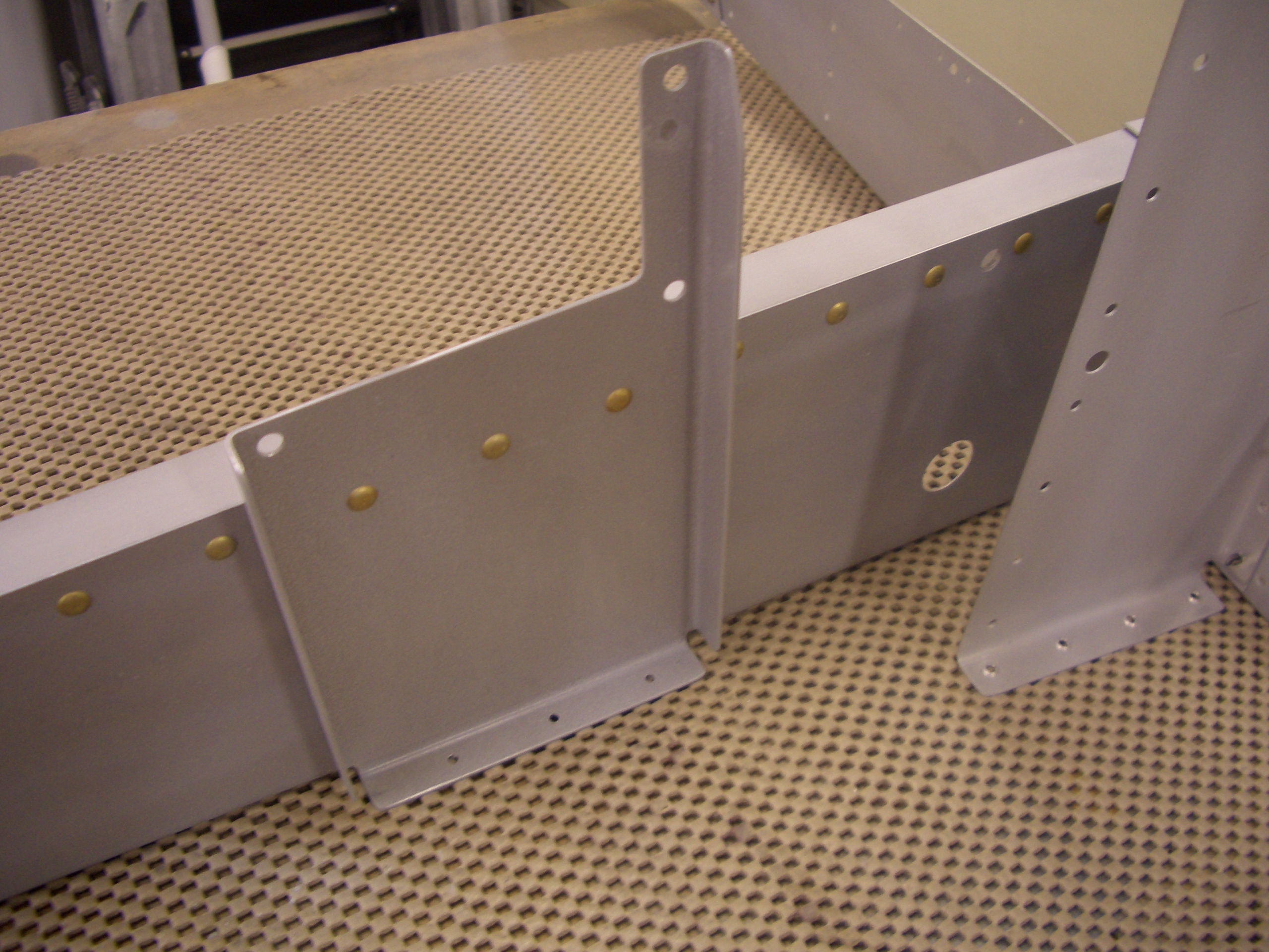
Here’s how the bracket sits against the rib. The flange on the bottom can be cut off or drilled to the skin (which I’m doing).
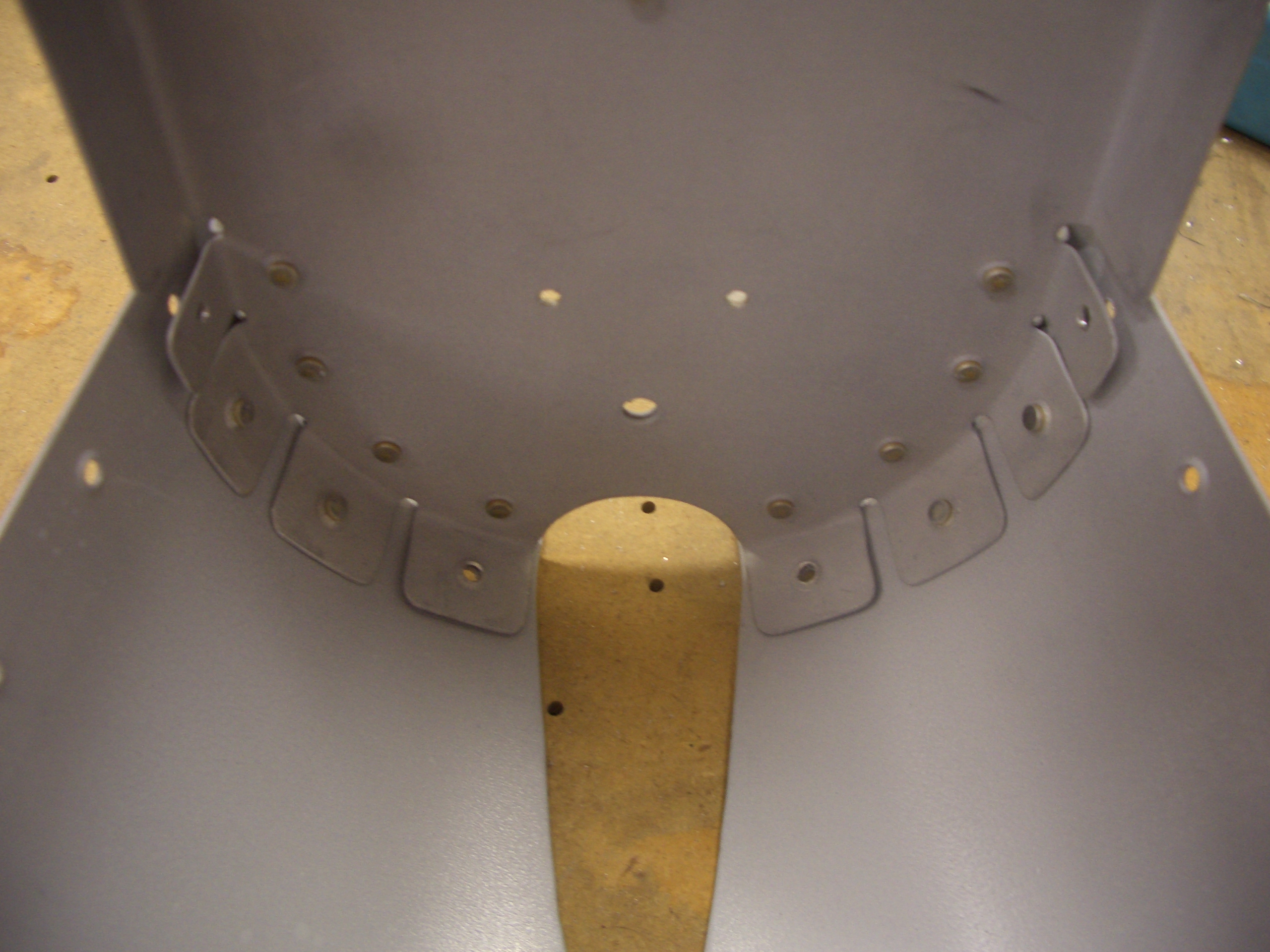
After match drilling the bracket to the rib, I laid out for rivet holes aligned with the ones in the rib (as if aesthetics matter on the bottom of the aircraft).
After clecoing the structure back to the bottom skin (and using a clamp to keep the bracket tight against the rib), I match drilled the skin to the bracket.
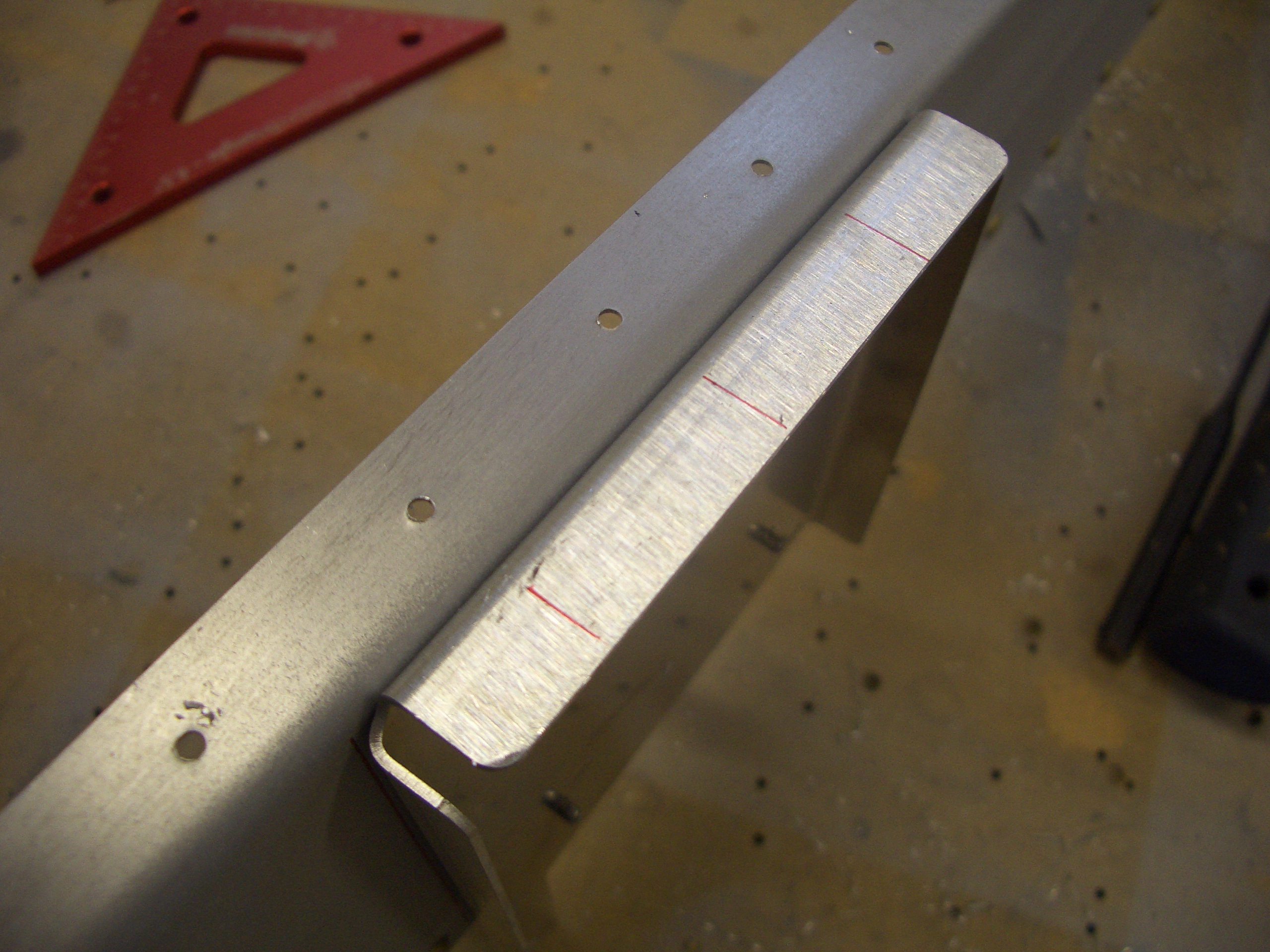
The F-710 bulkhead needs a piece of 1/8″x1″x1″ angle fabricated to sit at the top edge. The ends have to be tapered and shaped to nest into the longerons.
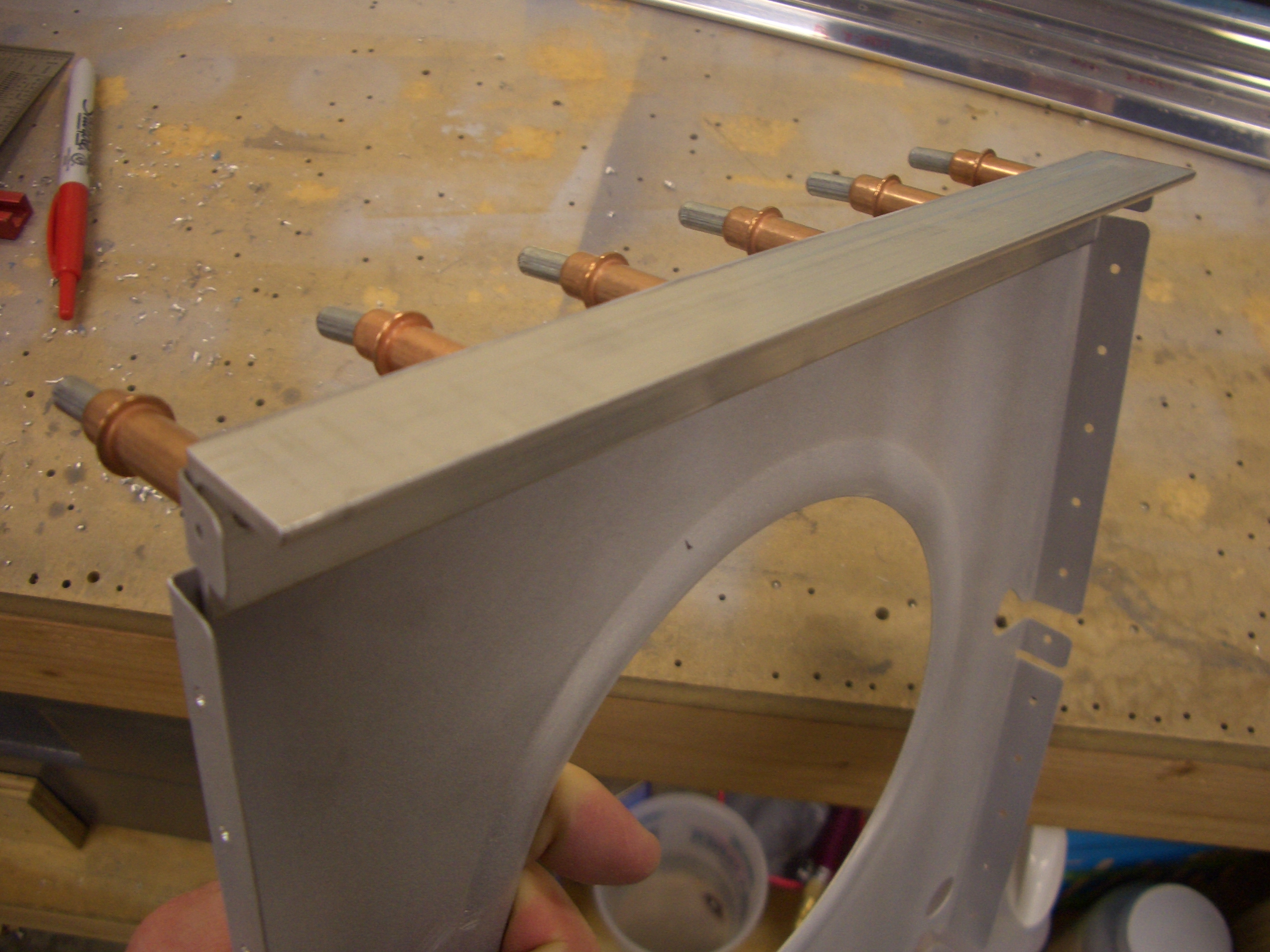
The F-711 bulkhead also needs a piece of 1/8″x3/4″x3/4″ angle, also with tapered and shaped ends. This won’t get riveted on until the side skins are riveted to the longerons.
Here you can see why. The longerons rivet to this flange on the bulkhead which is covered by the angle I just fabricated. In fact, I had to notch the ends of the angle here to clear the future shop head for this rivet.
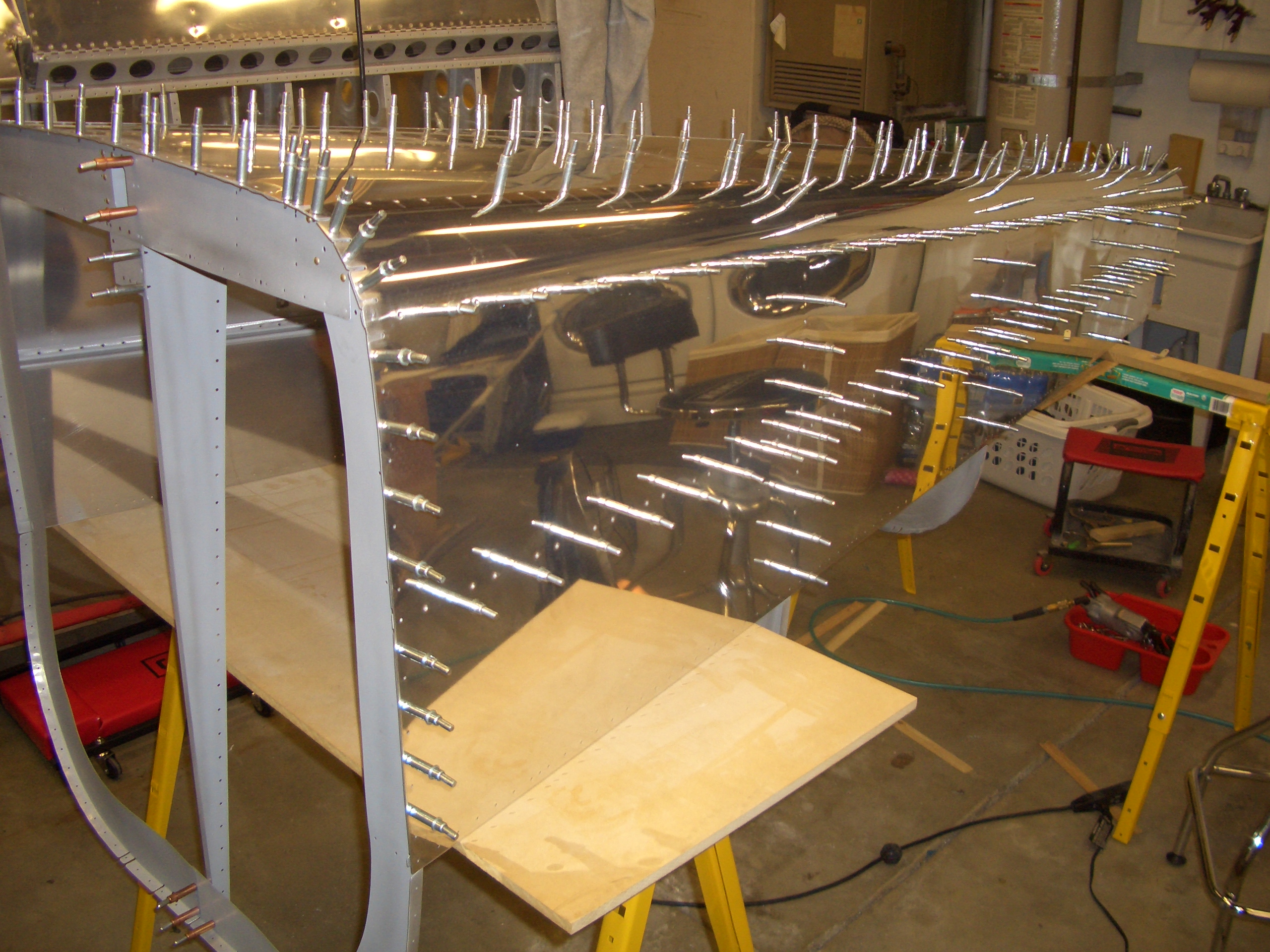
The tailcone is now fully disassembled so I can begin deburring, dimpling, and priming.
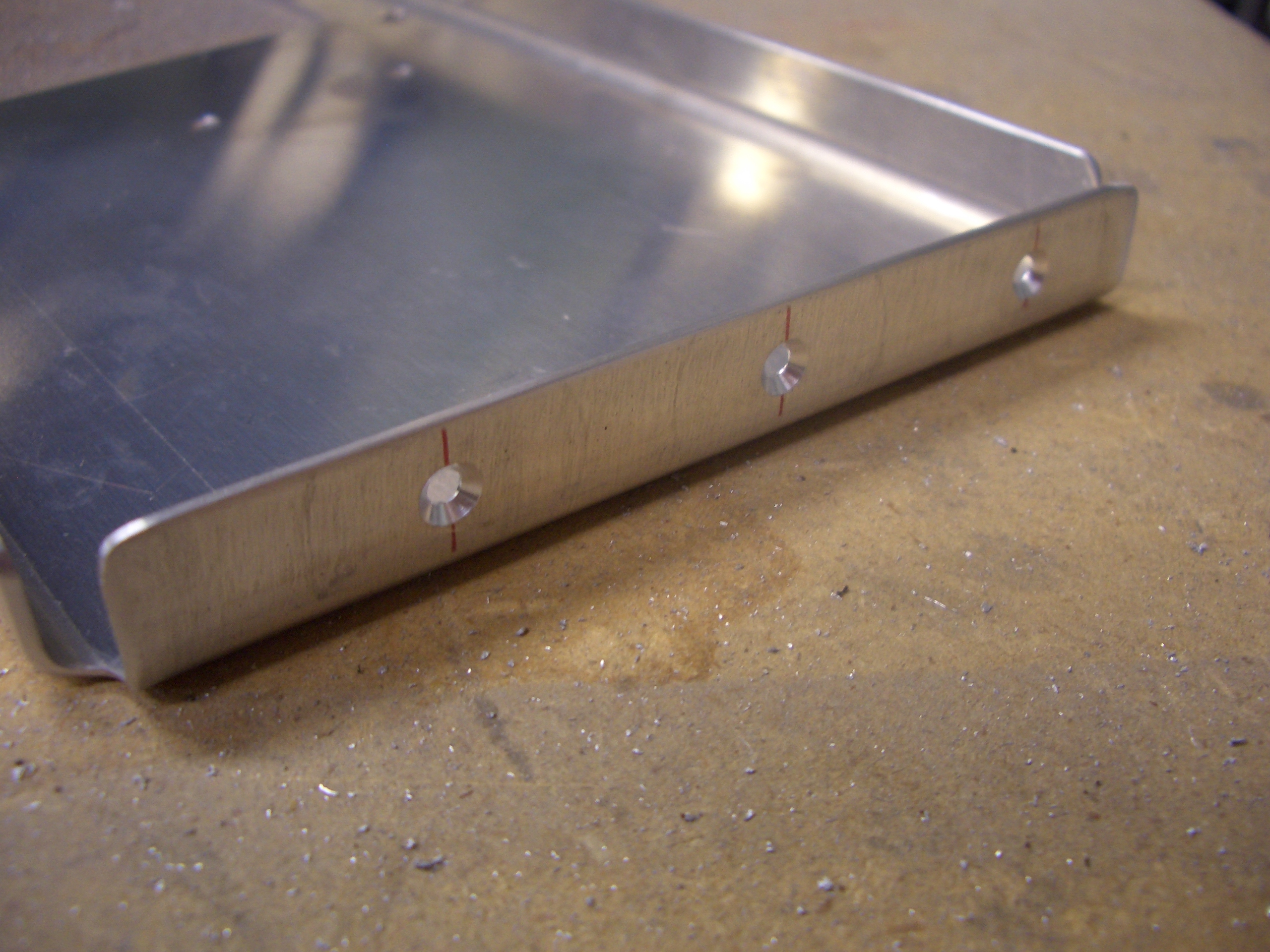
The bracket is 0.048″ thick, so it can’t be dimpled. Instead, I machine countersunk the holes here to receive the skin dimples.
I started deburring parts, but ran out of steam. I’d like to finish this up this weekend so I can get the tailcone riveted together before the holidays.
Deburring and Dimpling Tailcone
No pictures again tonight since it’s still just a pile of parts, but I made a good dent in deburring and dimpling the parts. Tomorrow will be a long build day, so I’m hoping to finish these up and start riveting the tailcone together.
Prepped Tailcone for Riveting
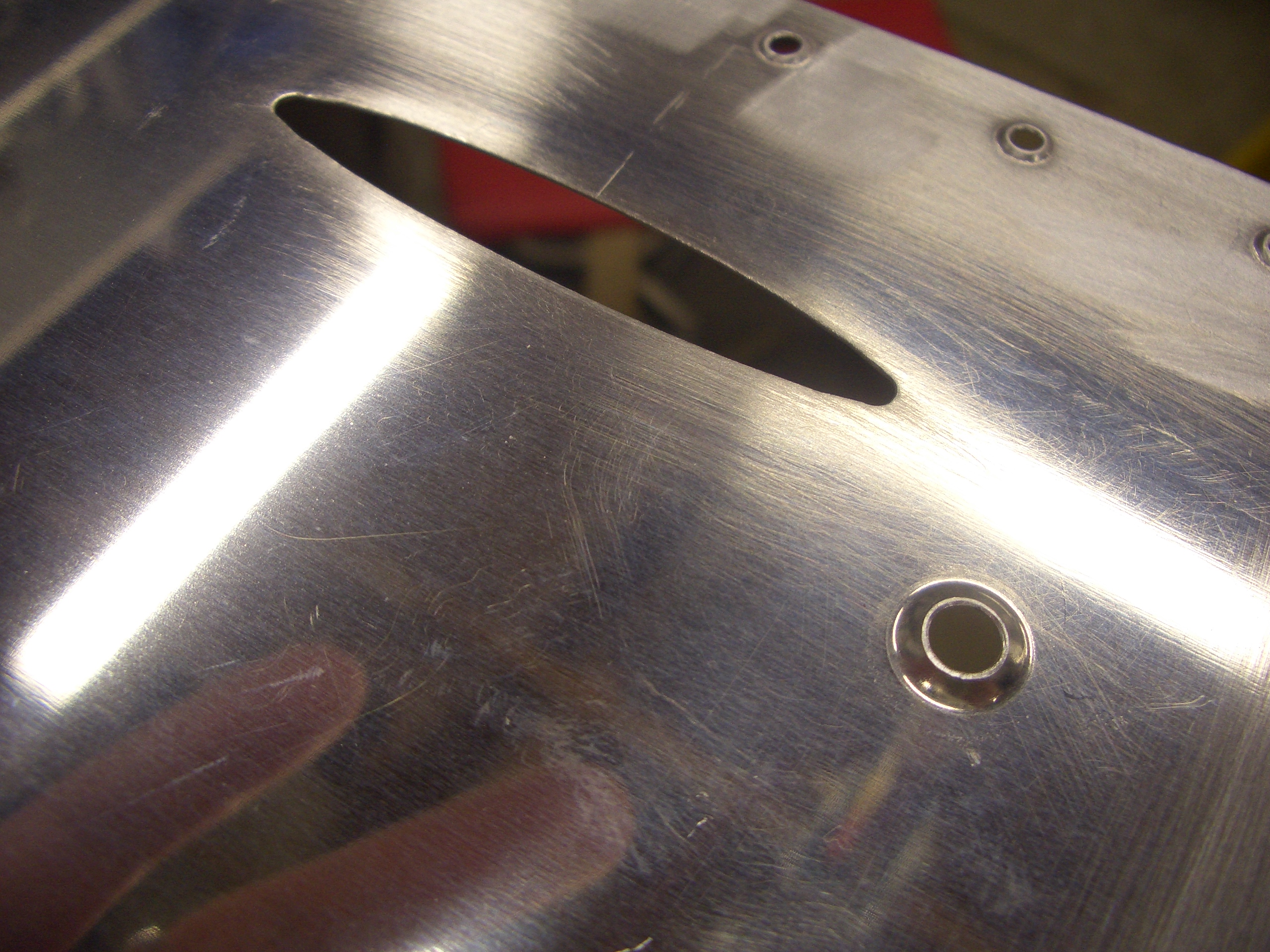
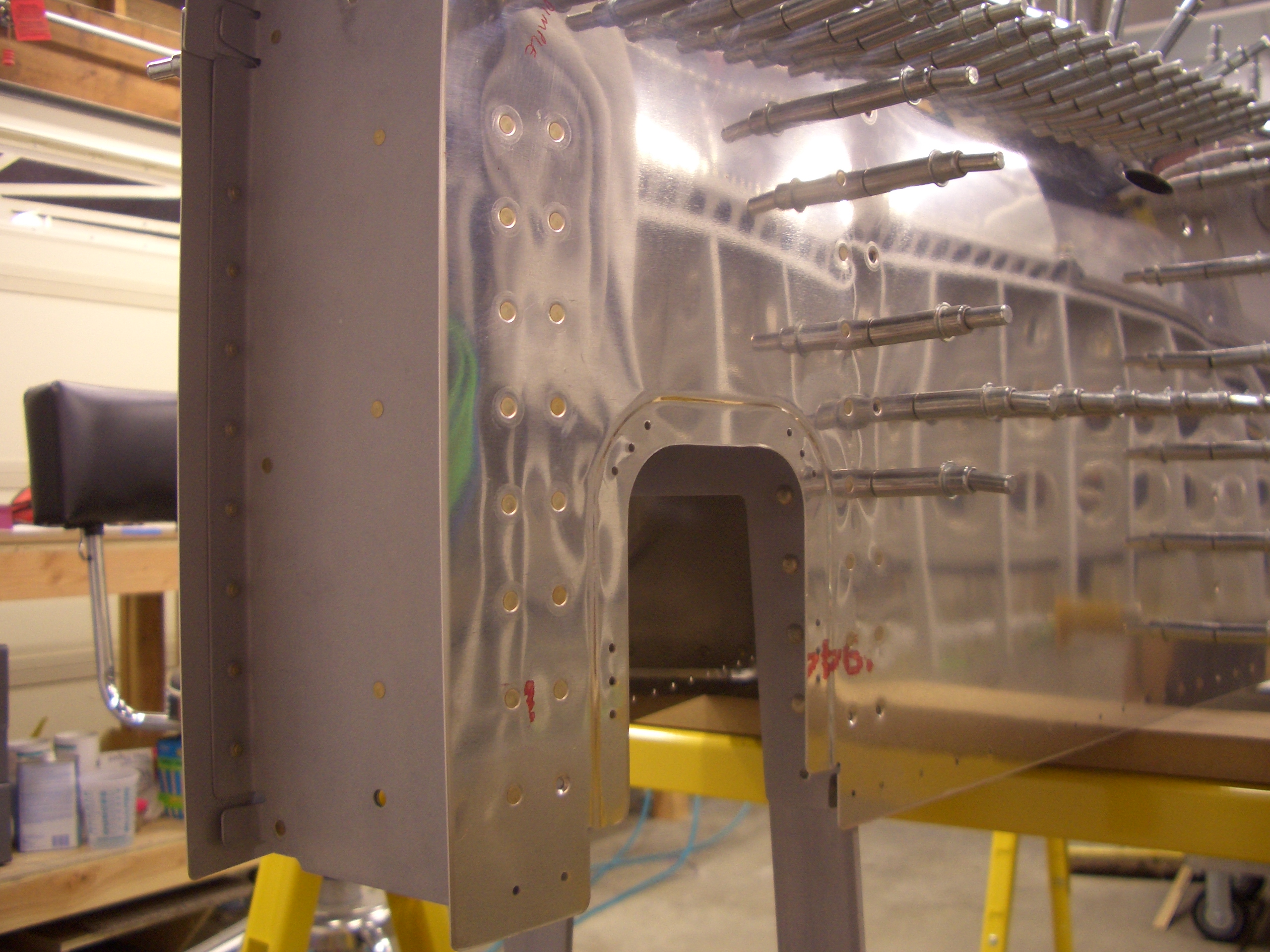
I did a little further trimming on the mousehole so that the tail skin also cleared the welds on either side of the tail spring mount. I haven’t decided if I’m going to paint the mount or have it powder coated yet. I’m going to call around tomorrow and see how much it would cost to have it powder coated.
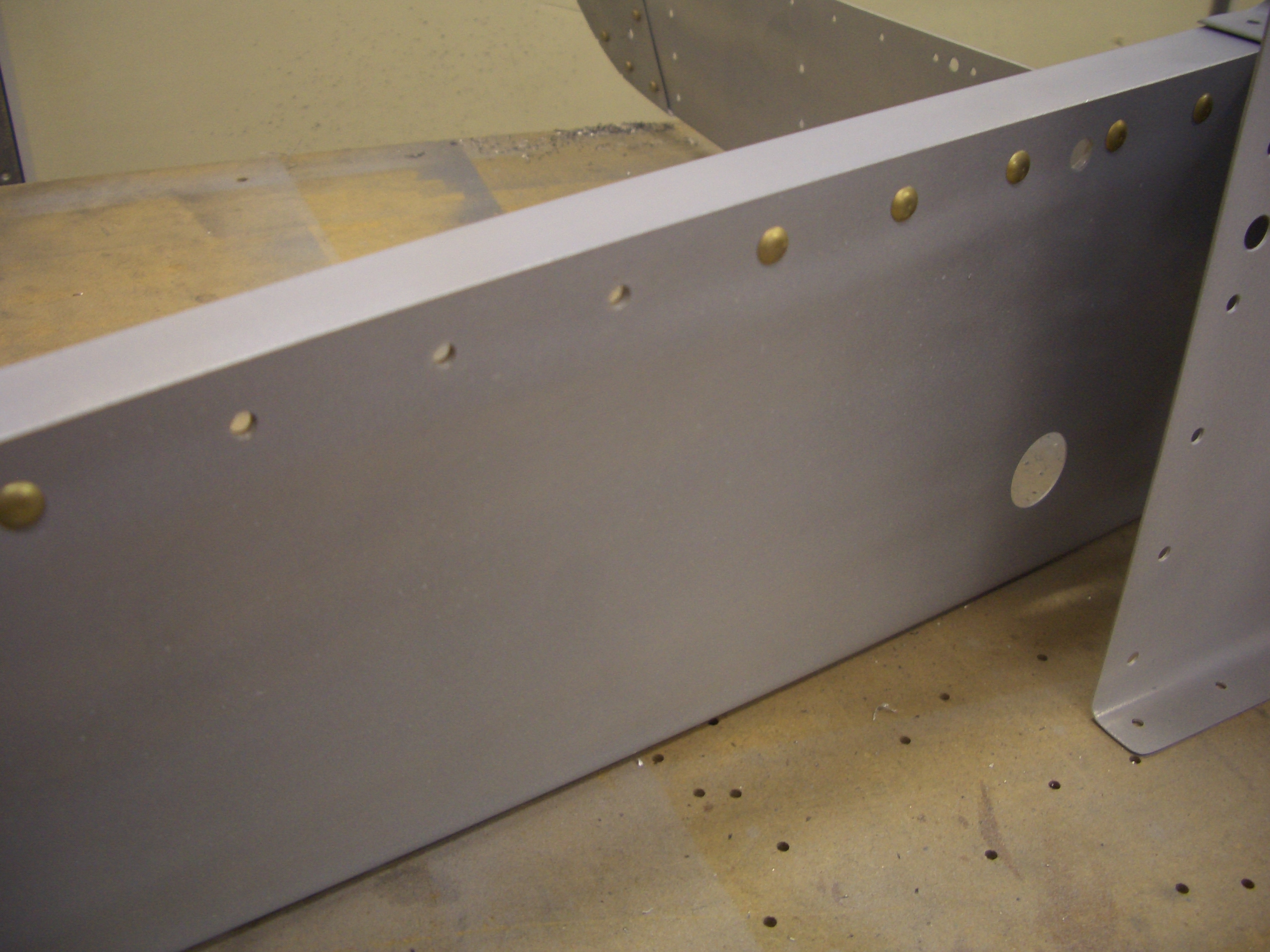
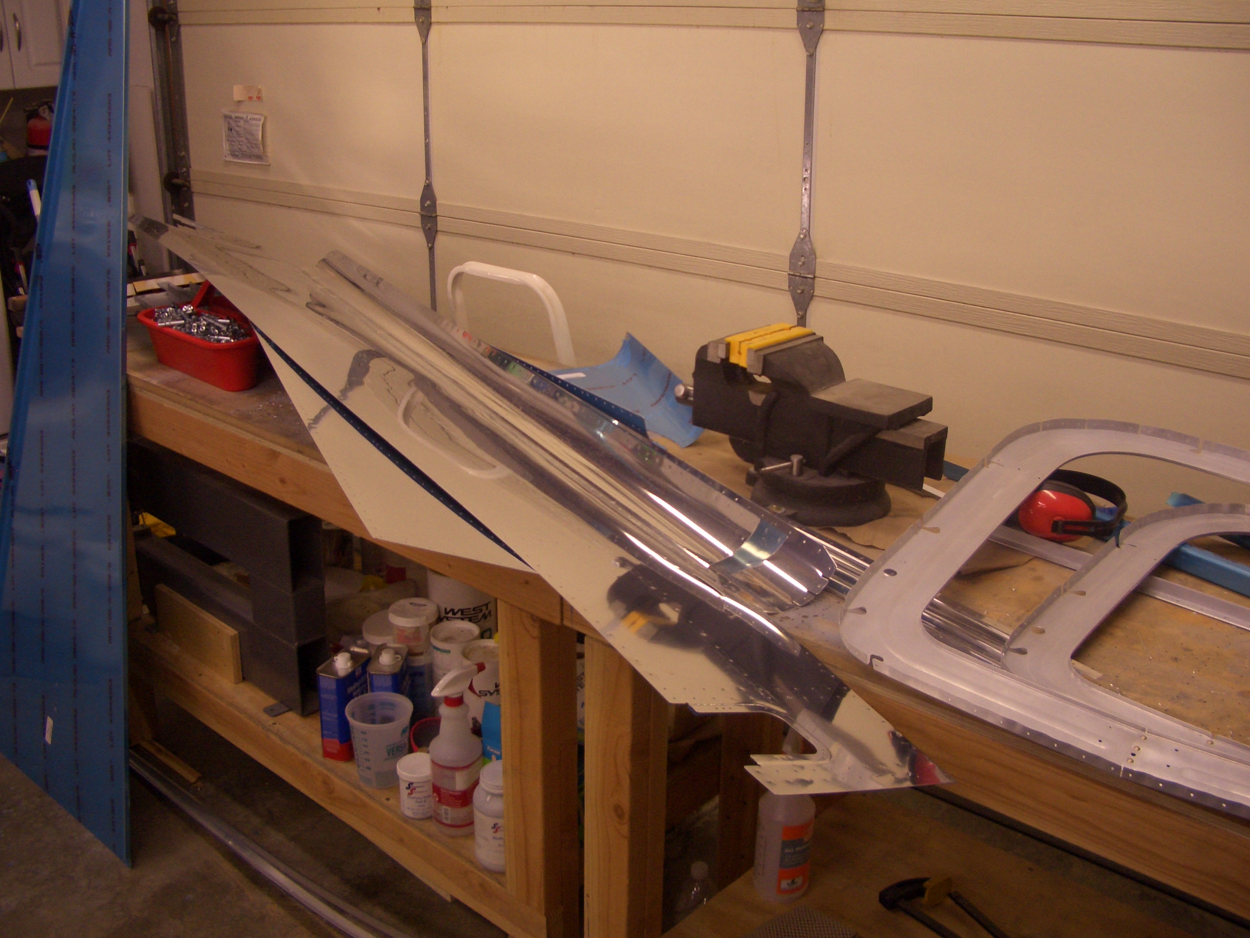
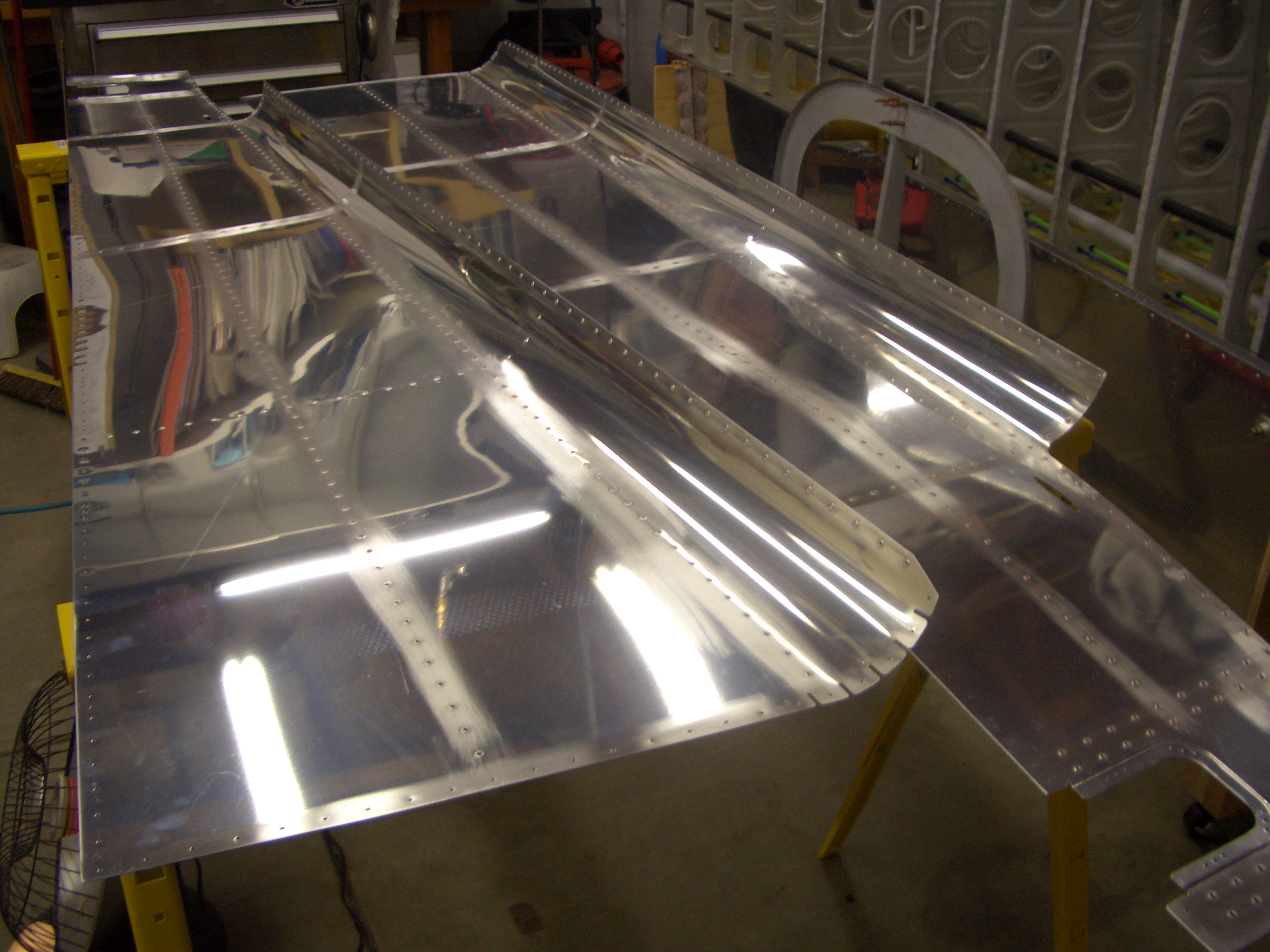
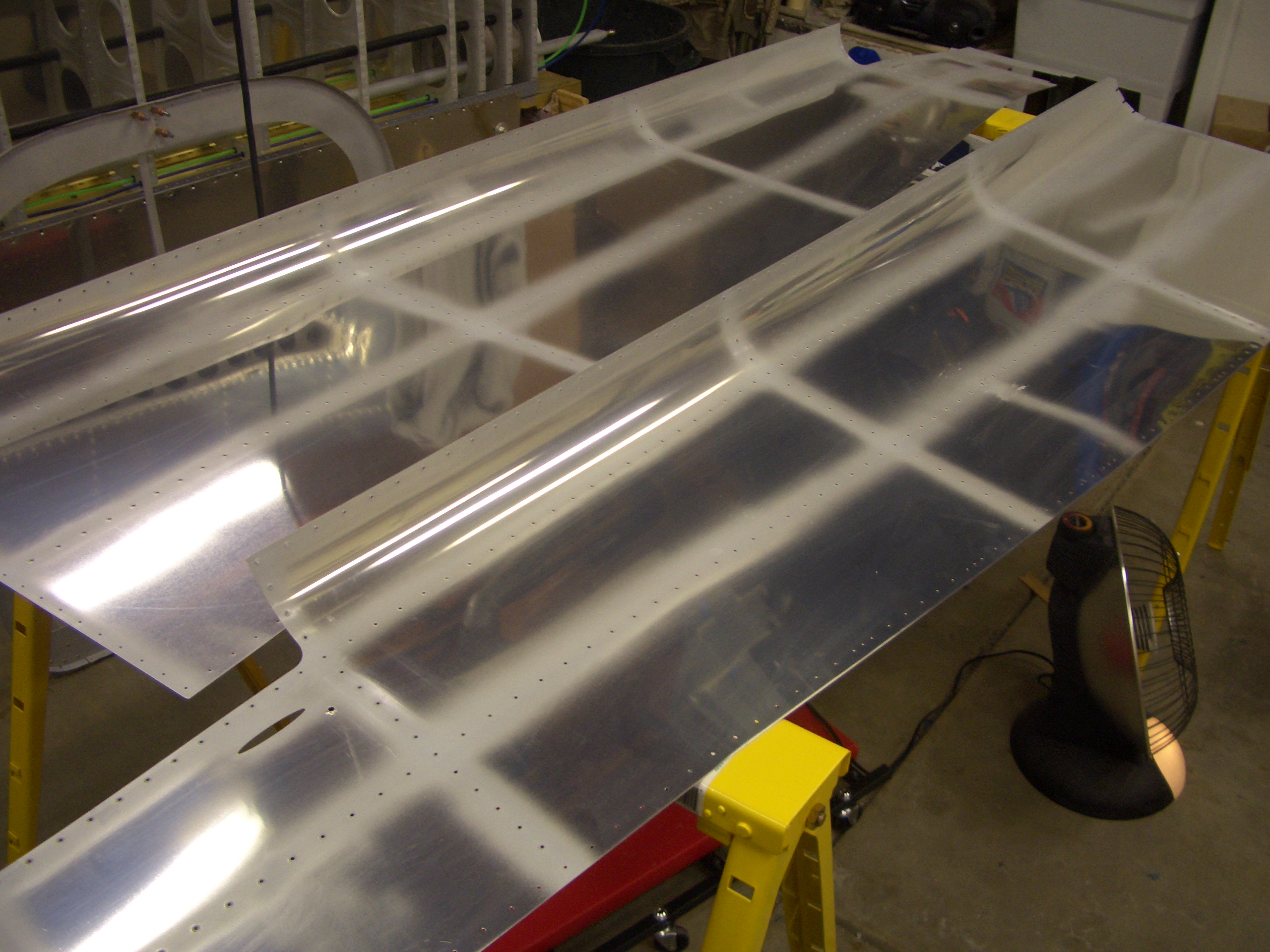
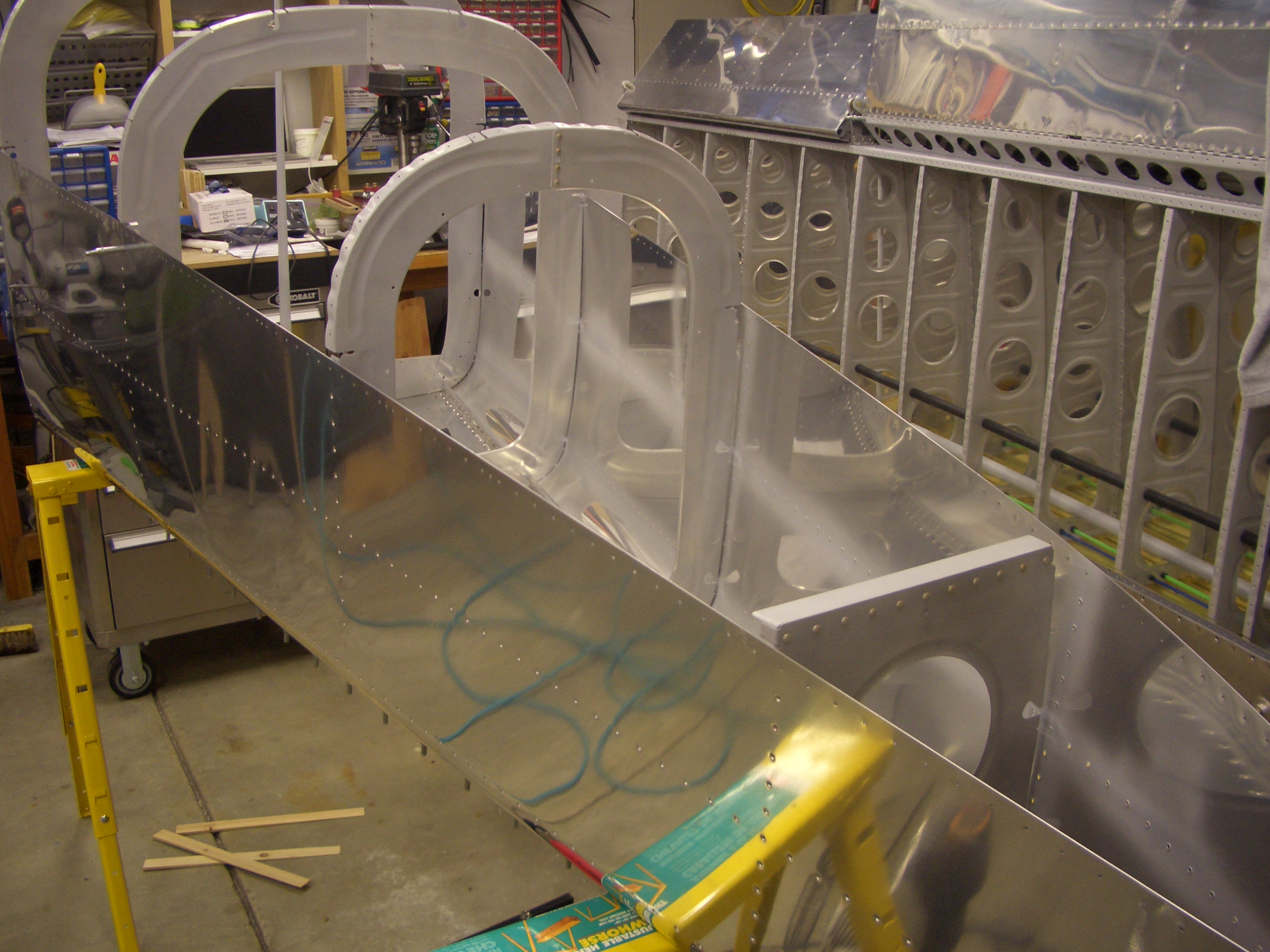
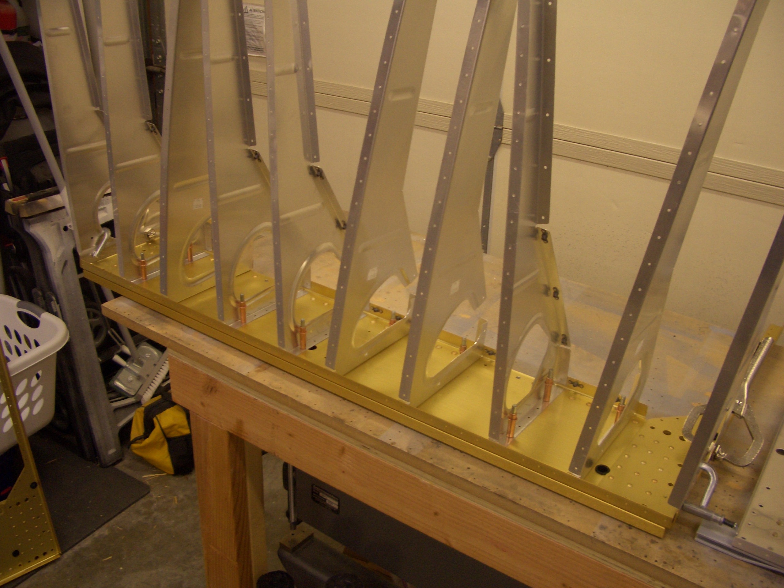
With my buddy Andre’s help, I finished prepping all of the tailcone components for priming. It’s a bit late tonight to start the priming, but it should be fairly easy to knock it out in the next day or two. Here is the bottom skin and all of the bulkheads behind it.
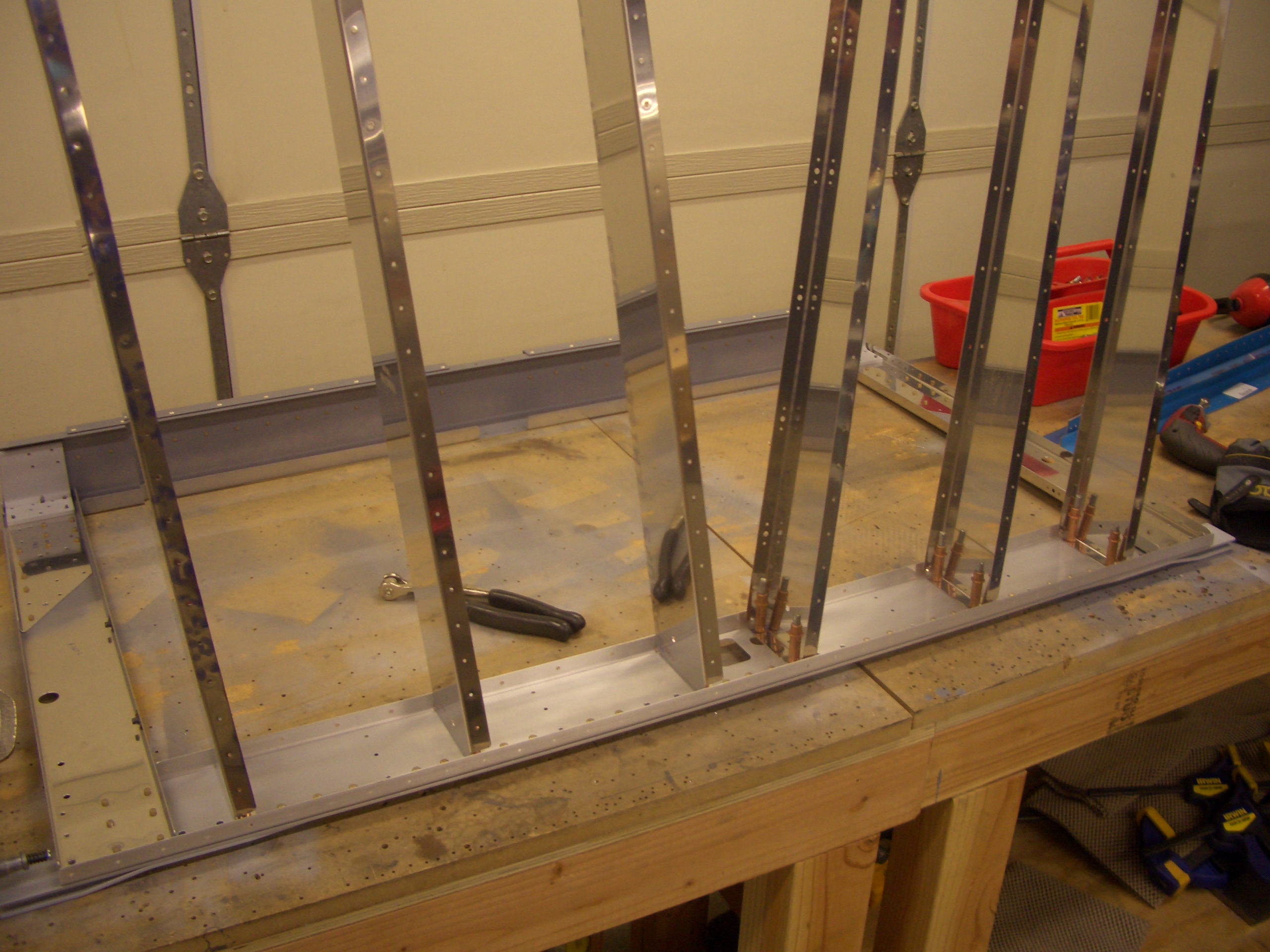
And here are the side skins. The skins got a little scratched up inserting and removing the stringers, so I scuffed up the rivet lines and will prime those.
Drilled New Tailwheel Spring Mount
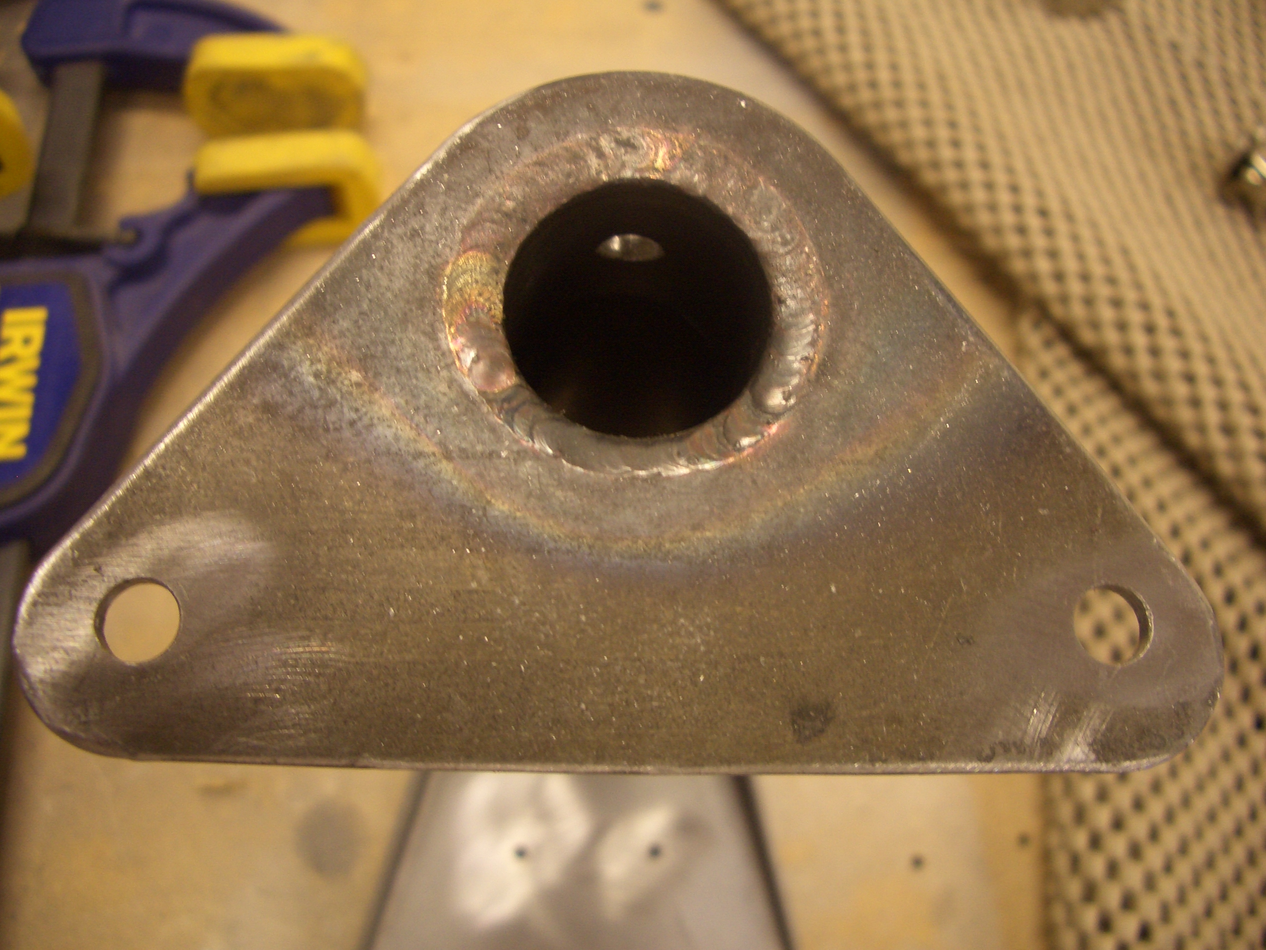
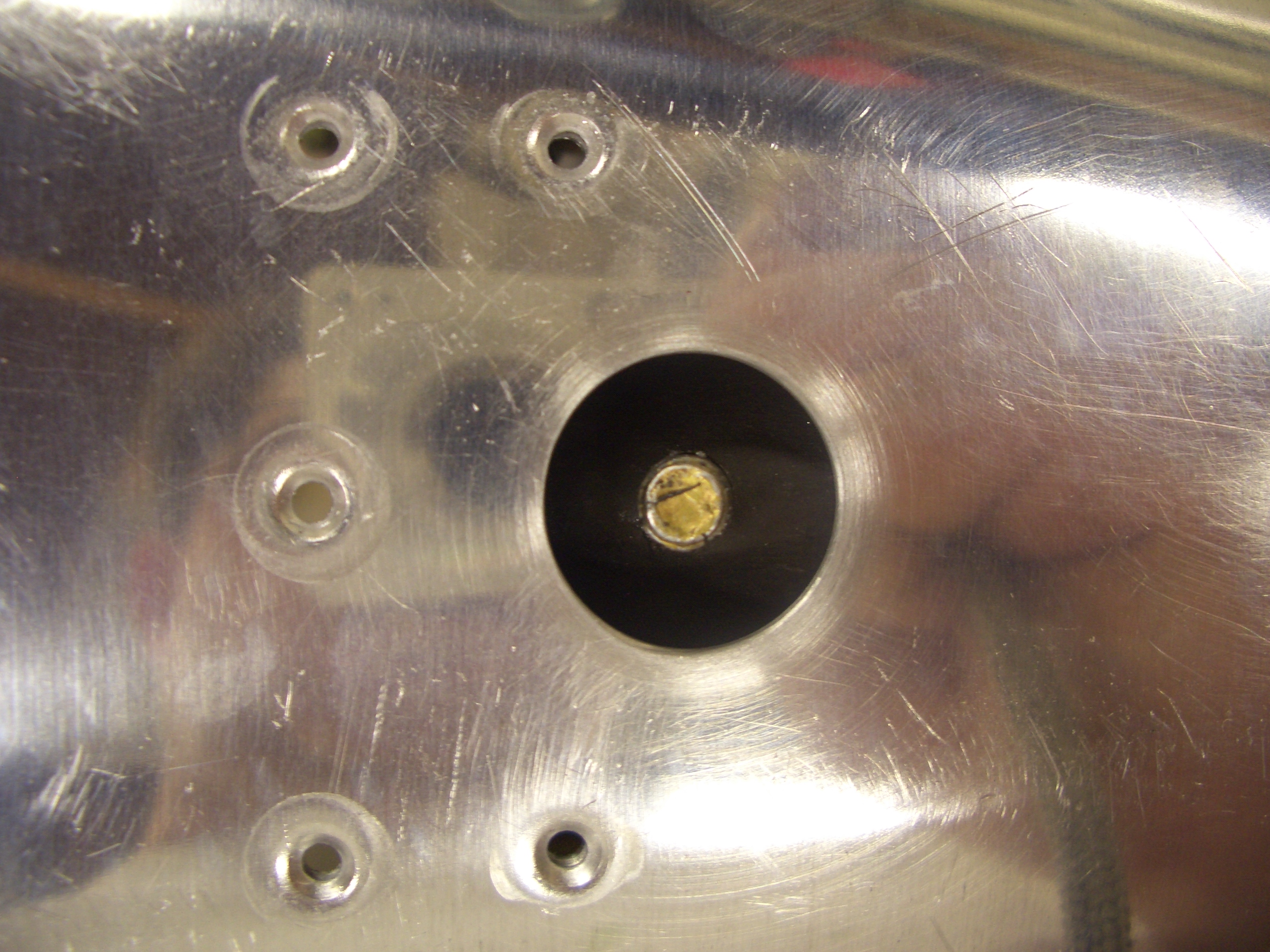
When I drilled my tailwheel spring mount, somehow one of the holes came out lower than it should (this picture is upside down, so the right hole looks too high). Van’s confirmed the reduced edge distance wasn’t an issue, but I wanted to make sure the misplaced hole wasn’t causing the mount to be cocked to one side. I clecoed the two rear bulkheads back to the tail skin with the mount between them and took a bunch of measurements.
Despite my best effort at positioning the mount, the tailwheel was cocked to one side about 2º. I don’t know if that is significant enough that it would affect the handling, but it would be virtually impossible to change later, and it would bug me knowing that it’s not correct, so I ordered a new one from Van’s. It came in today, so I wanted to get it drilled to the fuselage tonight.
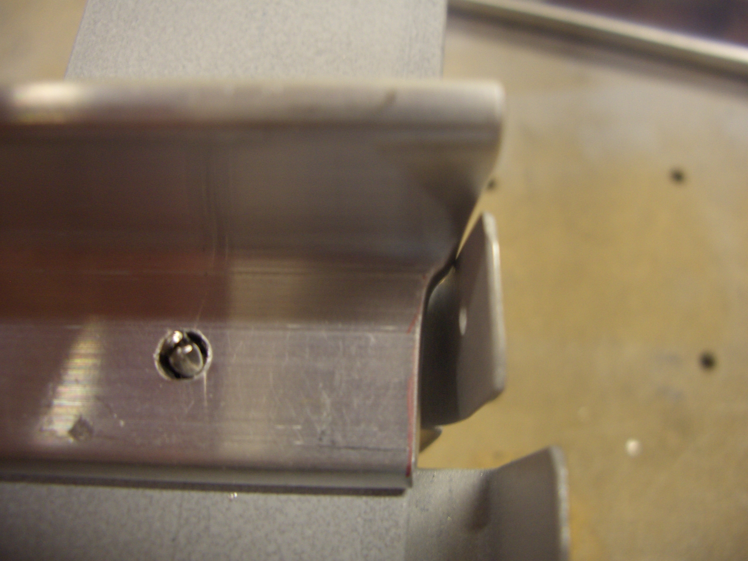
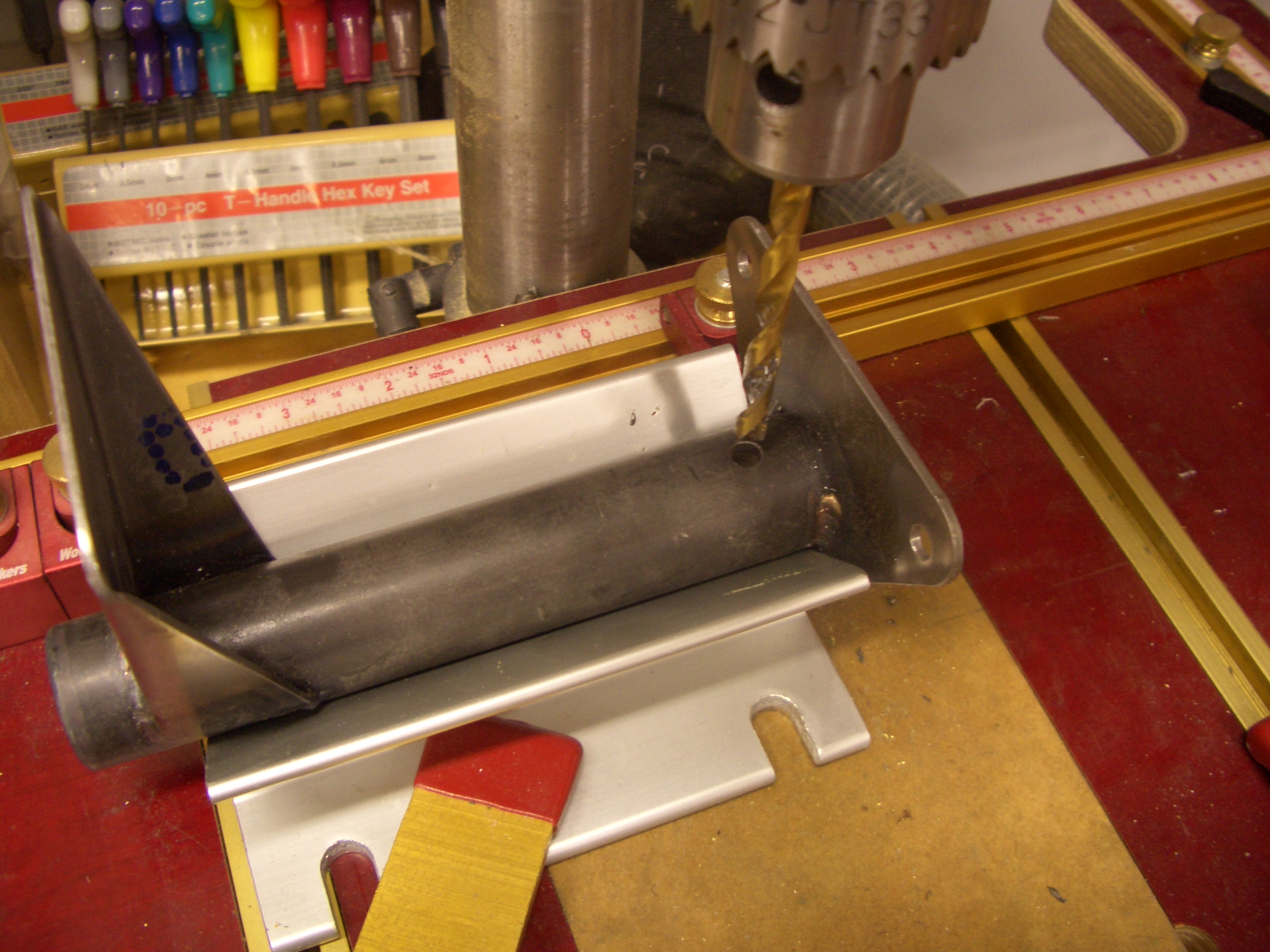
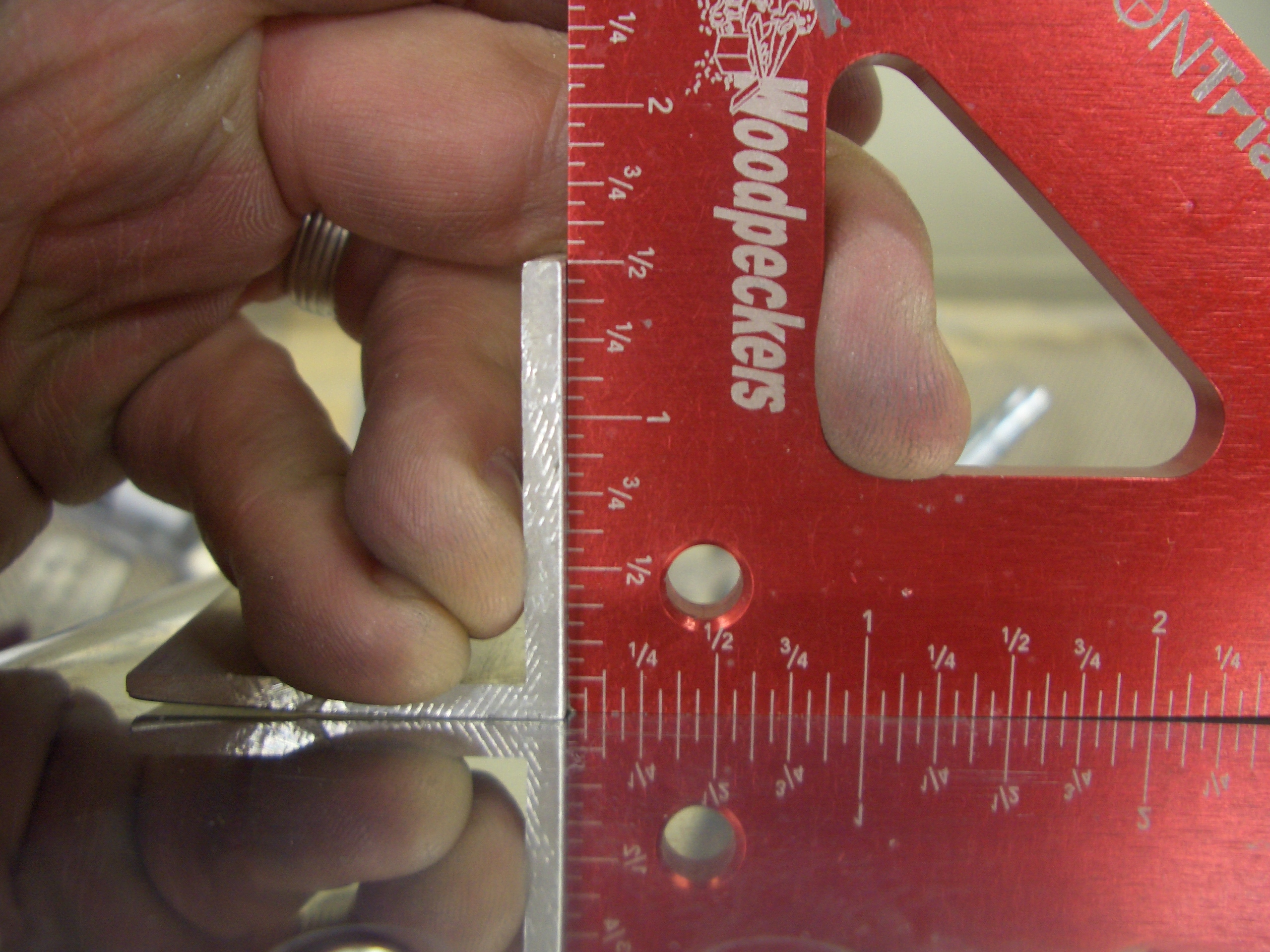
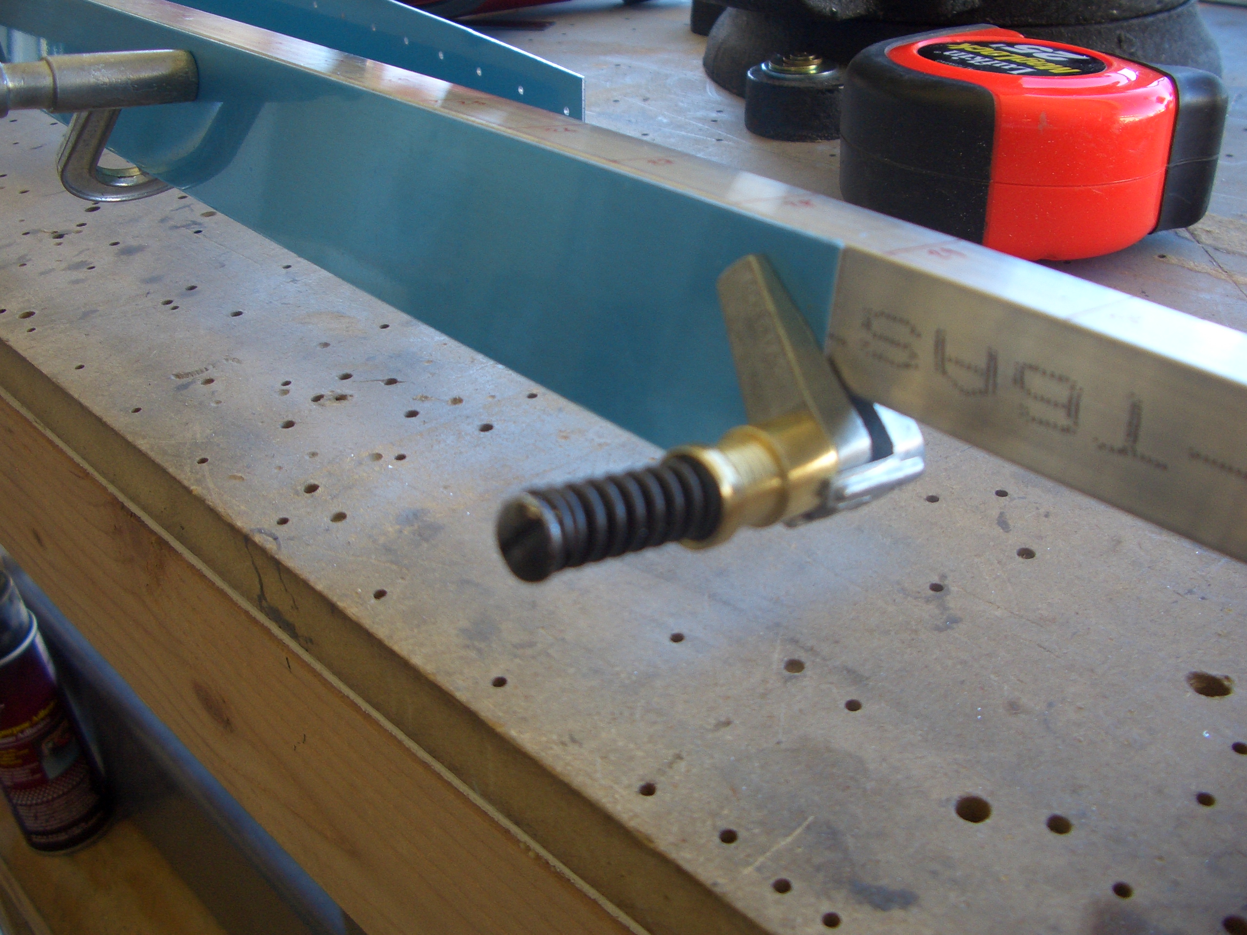
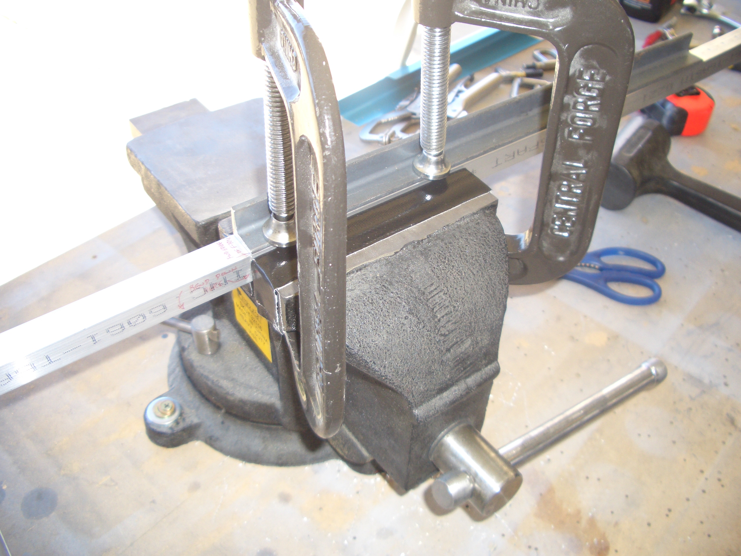
Unfortunately, the new mount didn’t have the hole drilled in it that attaches the mount to the spring (the one under the drill bit). I needed to figure out how to drill a hole in the mount that would somehow line up with the hole in the spring inside. What I ended up doing was positioning my v-block so that the hole would be the right distance from the right end when the flange was butted up against the v-block. I then took a reading with my digital level of the angle of the flange top edge when the drill bit was pushed all the way through the old mount. I then positioned the new mount so the flange top edge was at the same angle and clamped it down. I drilled through the top wall of the tube and then put the spring in place and lined up the holes. I then used that as a guide to drill the bottom wall of the tube. This resulted in perfect alignment of the holes.
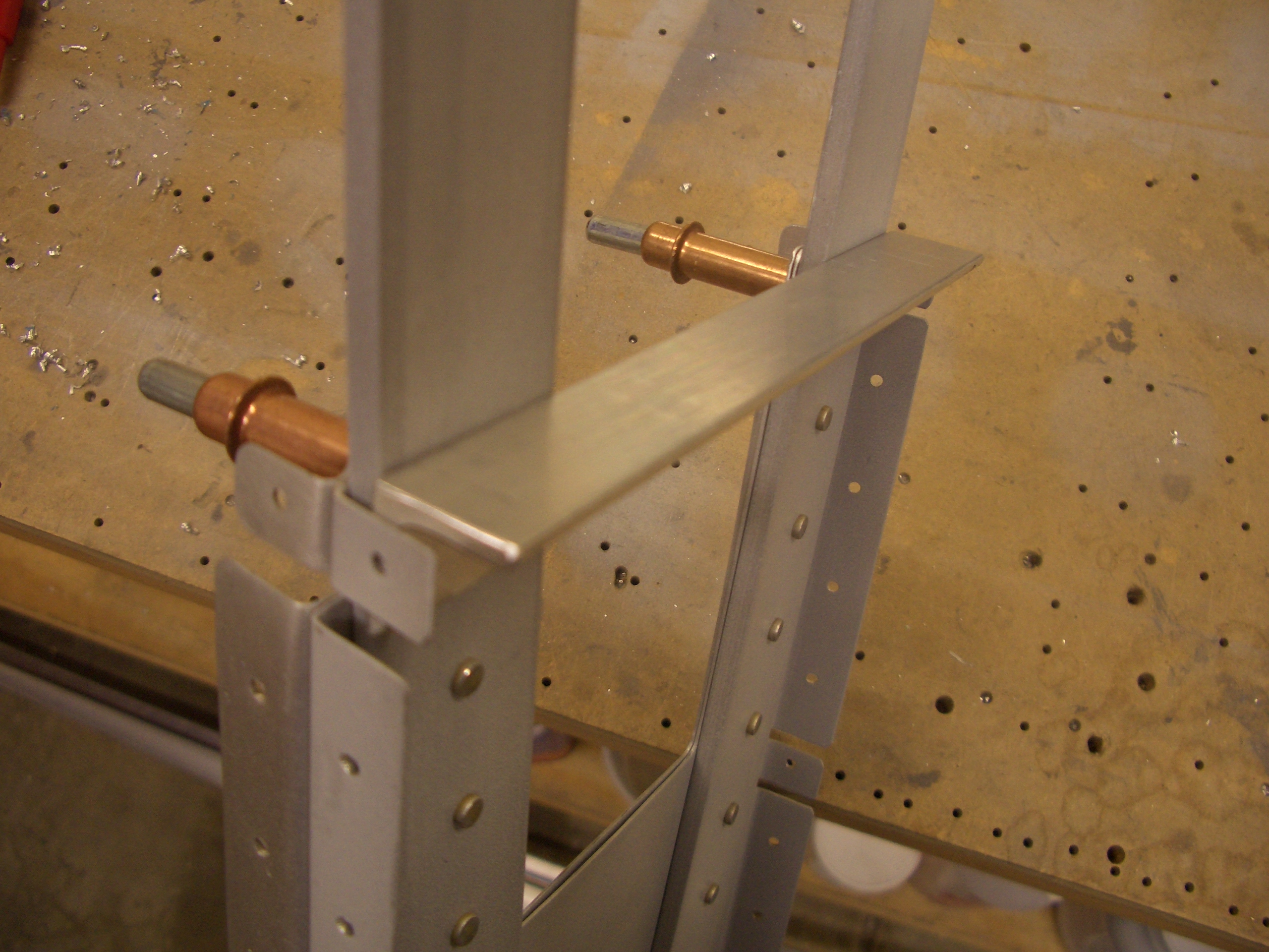
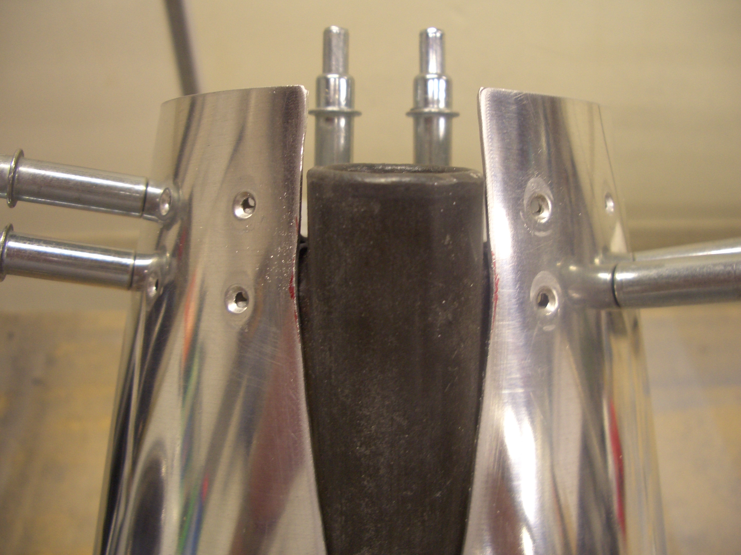
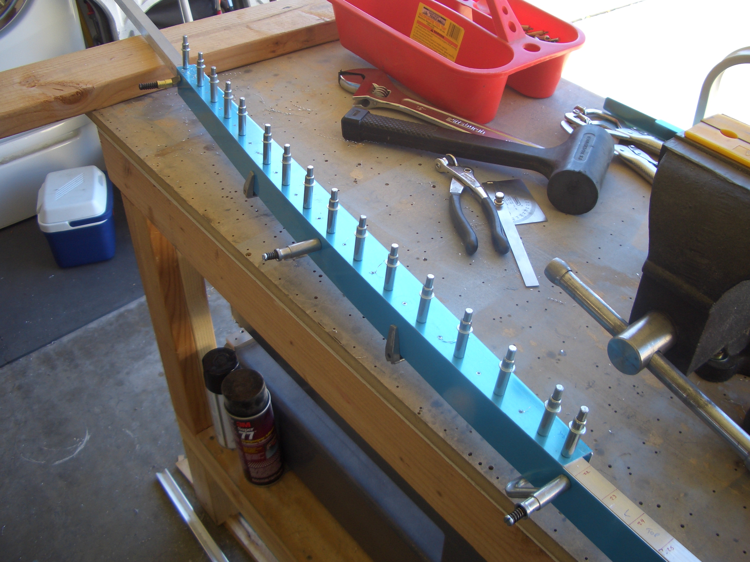
I then used some scrap 1/8″ angle to make sure the tailwheel fork tube was exactly perpendicular to the tail skin. This picture shows how the angle is clamped to the tailwheel fork tube and rests on the tail skin.
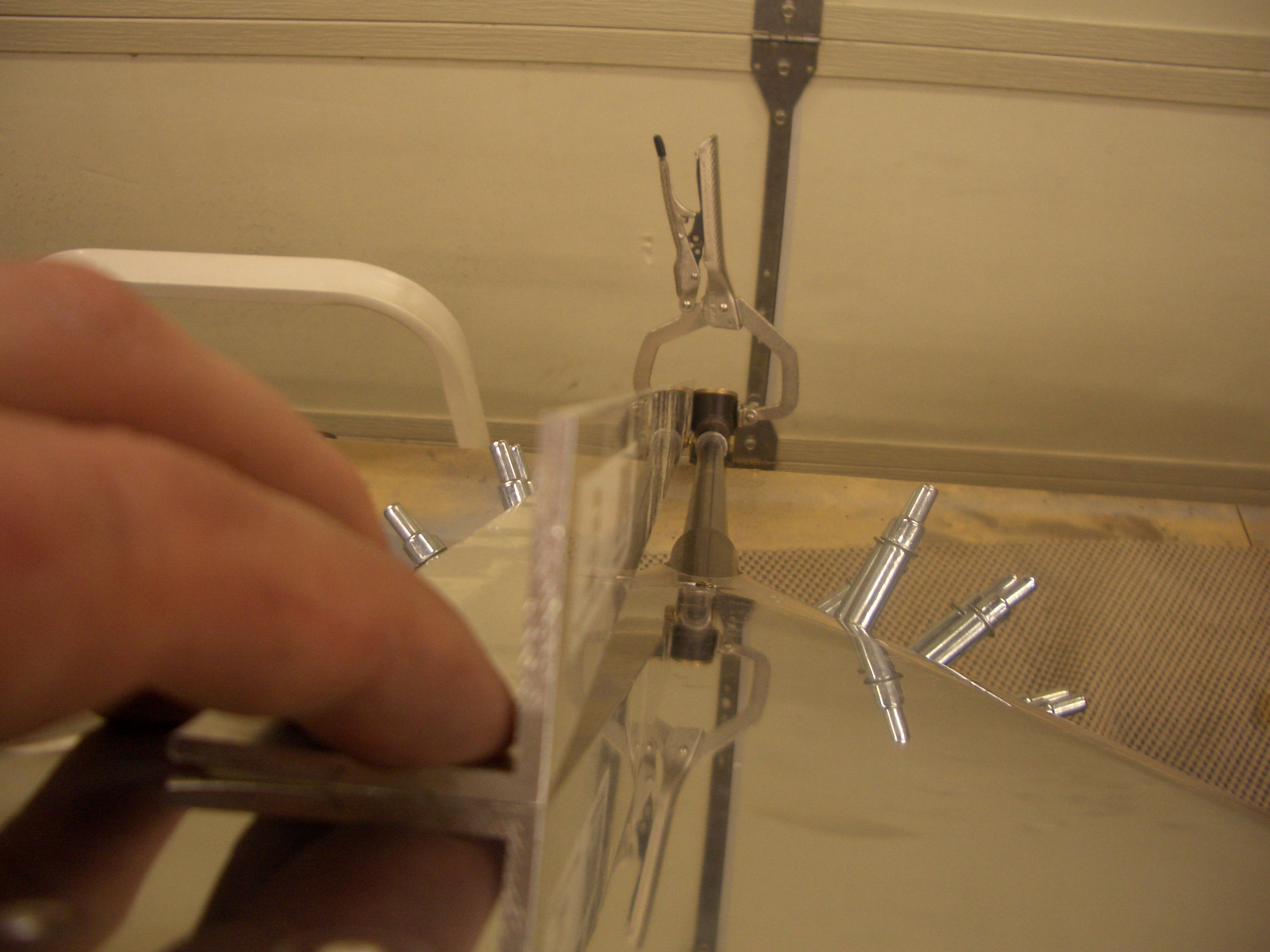
And here you can see that this is perfectly perpendicular. I clamped the angle to both sides of the tailwheel fork tube to make sure the measurements agreed.
This shows that the tailspring bolt is perfectly centered in the hole in the tail skin (with the old mount, the bolt was cocked noticeably to one side). After everything was clamped in place, I drilled the mount to the F-711 and F-712 bulkheads. I double checked that the tailwheel fork tube was straight, and it was perfect (easily within 0.1º of vertical); I feel much better now.
Primed Tailcone Components and Started Assembly
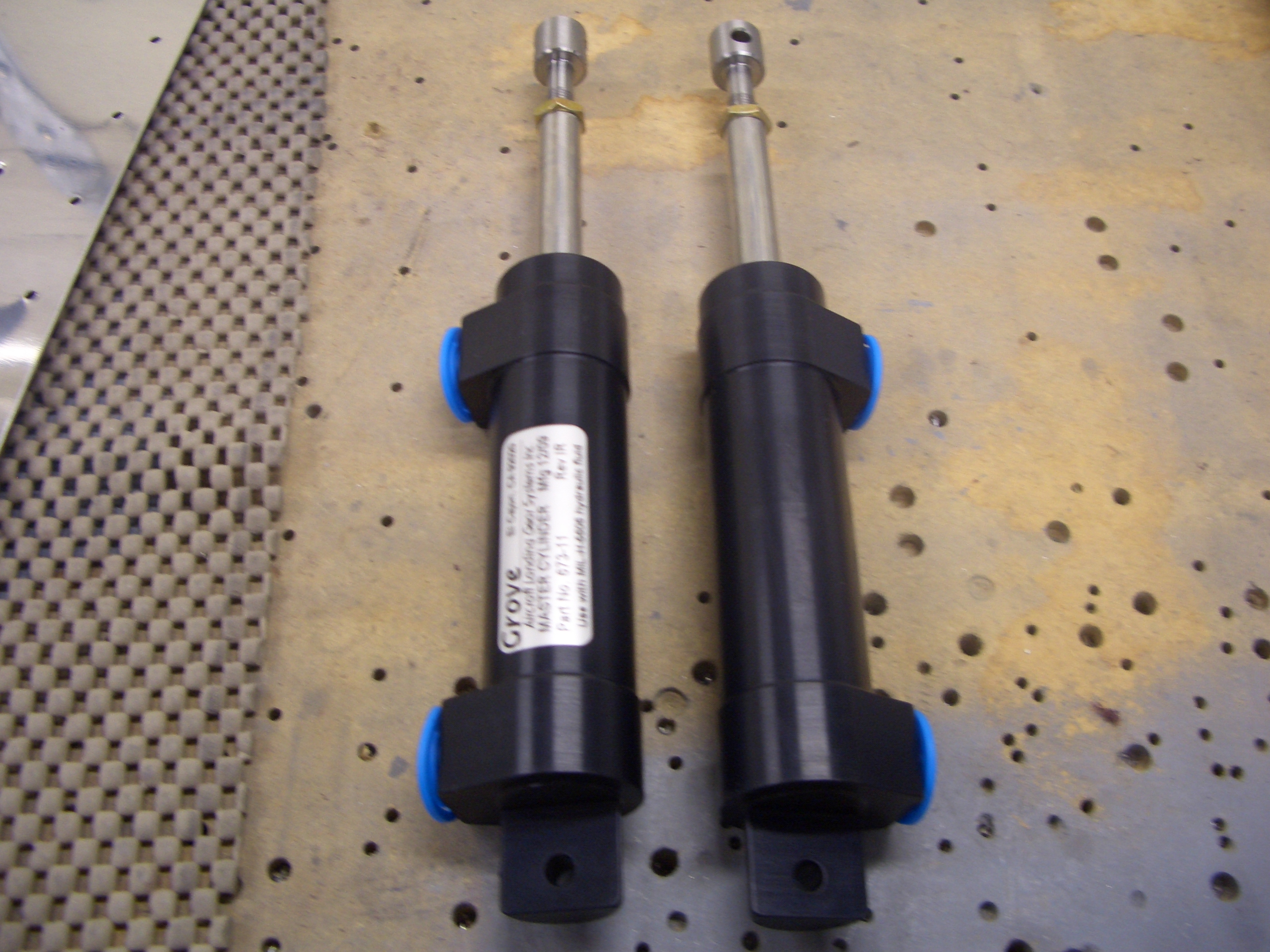
I received my Grove Aircraft master cylinders in the mail today. I decided to upgrade from the stock Matco master cylinders because people have had issues with them sticking. It appears that the issue can be addressed with external springs, but I don’t really like the way those look. Also, I heard such good things about the Grove cylinders that they seemed like the better choice. These have internal springs, so there should be no issue with them not extending fully when brake pressure is released.
Before reassembling the tailcone, I took care of one additional task that would be tough if I waited until later. I drilled the holes next to the rudder cable exit holes out to #19 and dimpled for a #8 screw. This will be used to attach an adel clamp to hold the rudder cable guide.
I primed all of the bulkhead and stringer seams since these got somewhat scratched up during the drilling.
I also primed the rest of the components for the tailcone.
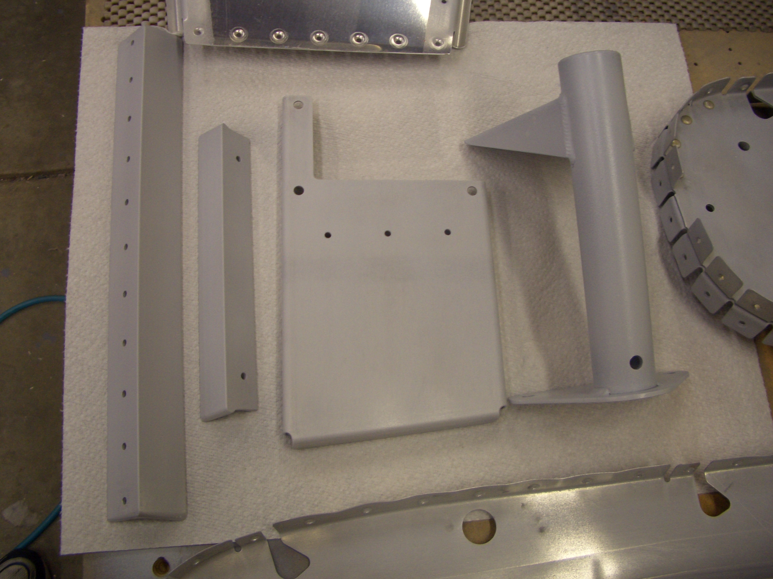
Since these are the lowest seams in the fuselage, I wanted to prime the overlap areas in case any water gets trapped there. I also primed the entire inside of the tail skin.
The top angle can now be riveted to the F-710 bulkhead.
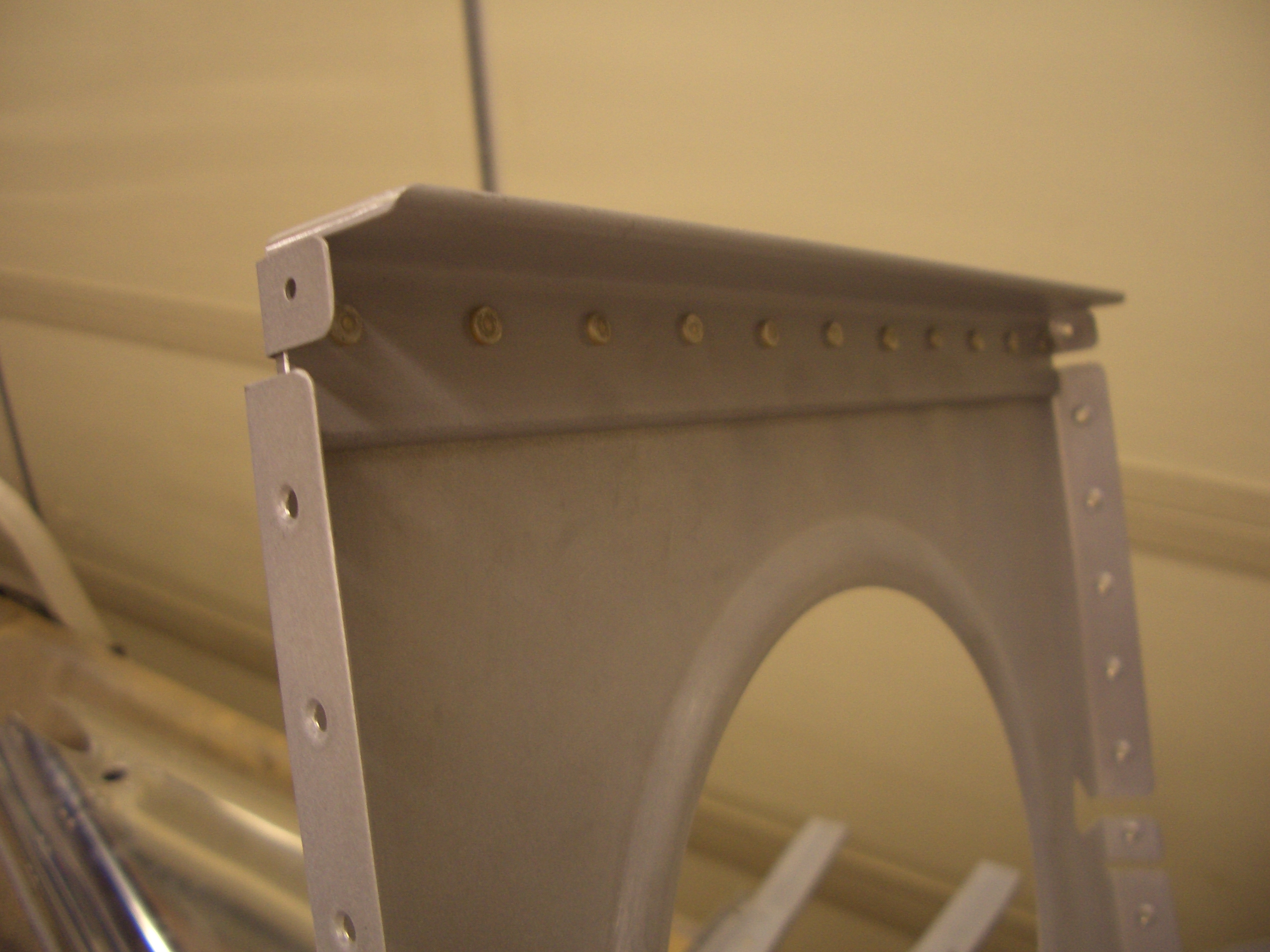
And F-712 can be riveted to the tail skin. These rivets were a little tricky to set, and I ended up drilling out two of them and replacing them. Since these flanges have an acute angle to the web, using the 4″ no-hole yoke with its thin nose made these easier.
Here are the rivets on the other side of F-712 (remember that it is a double bulkhead). The only ones that couldn’t be squeezed were the two lowest ones just next to the mouse hole. It’s too late to fire up the rivet gun tonight, so this will have to wait. I’m not ready to rivet the tail spring mount in place yet anyway since I want to give it a top coat of paint and the primer needs to dry for 24 hours.
I went ahead and riveted the autopilot pitch servo mounting bracket to the rib using some AN470AD4-5 rivets. Apparently, I had forgotten to dimple the holes in the bottom of this rib, so I did that now as well.
Finally, I got started clecoing the tailcone together. It was at this point that I noticed that I forgot to prime the stringers, so I had to stop for the night. I’ll do those tomorrow and then the tailcone can be fully clecoed together and riveting can begin.
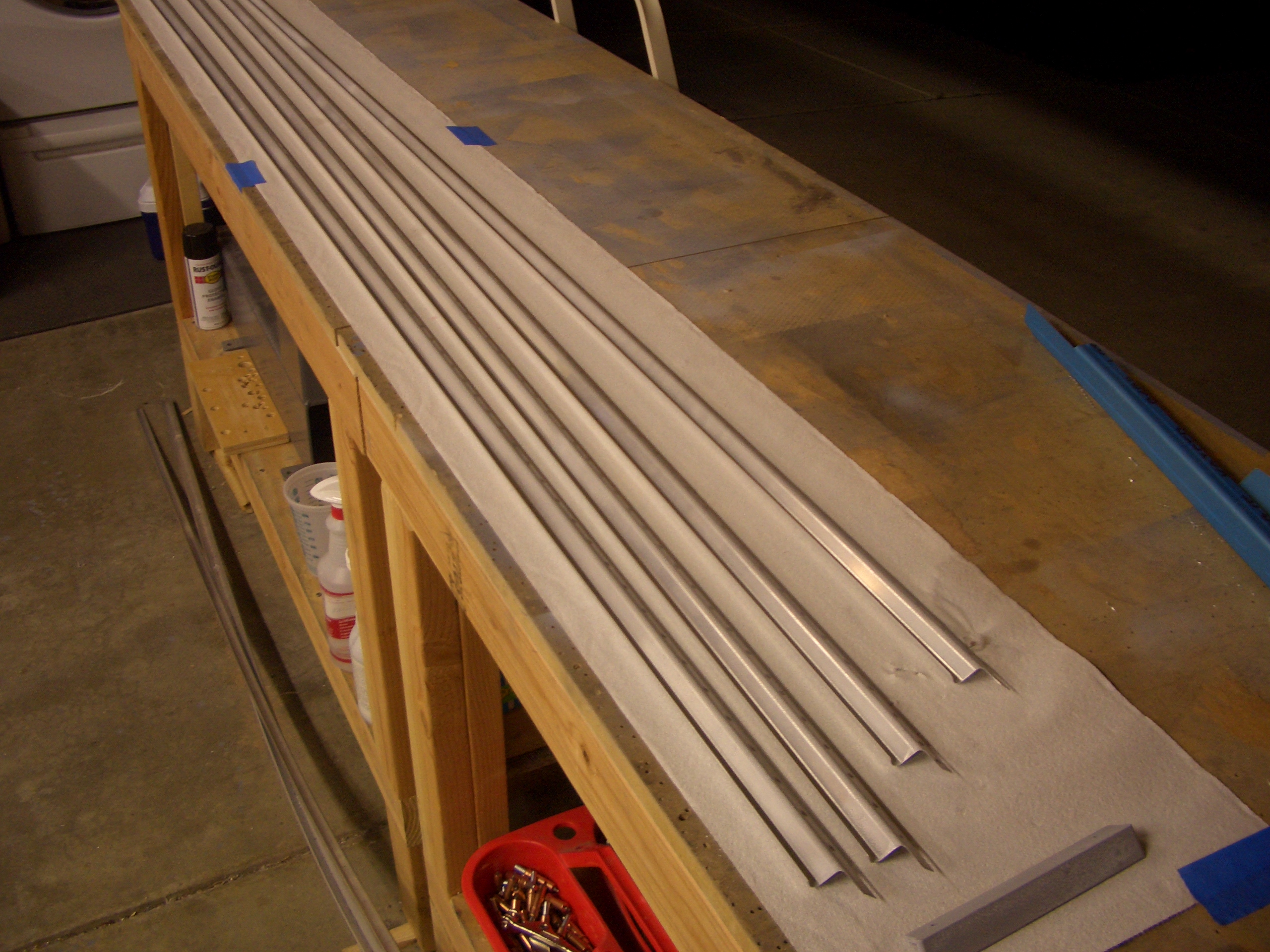
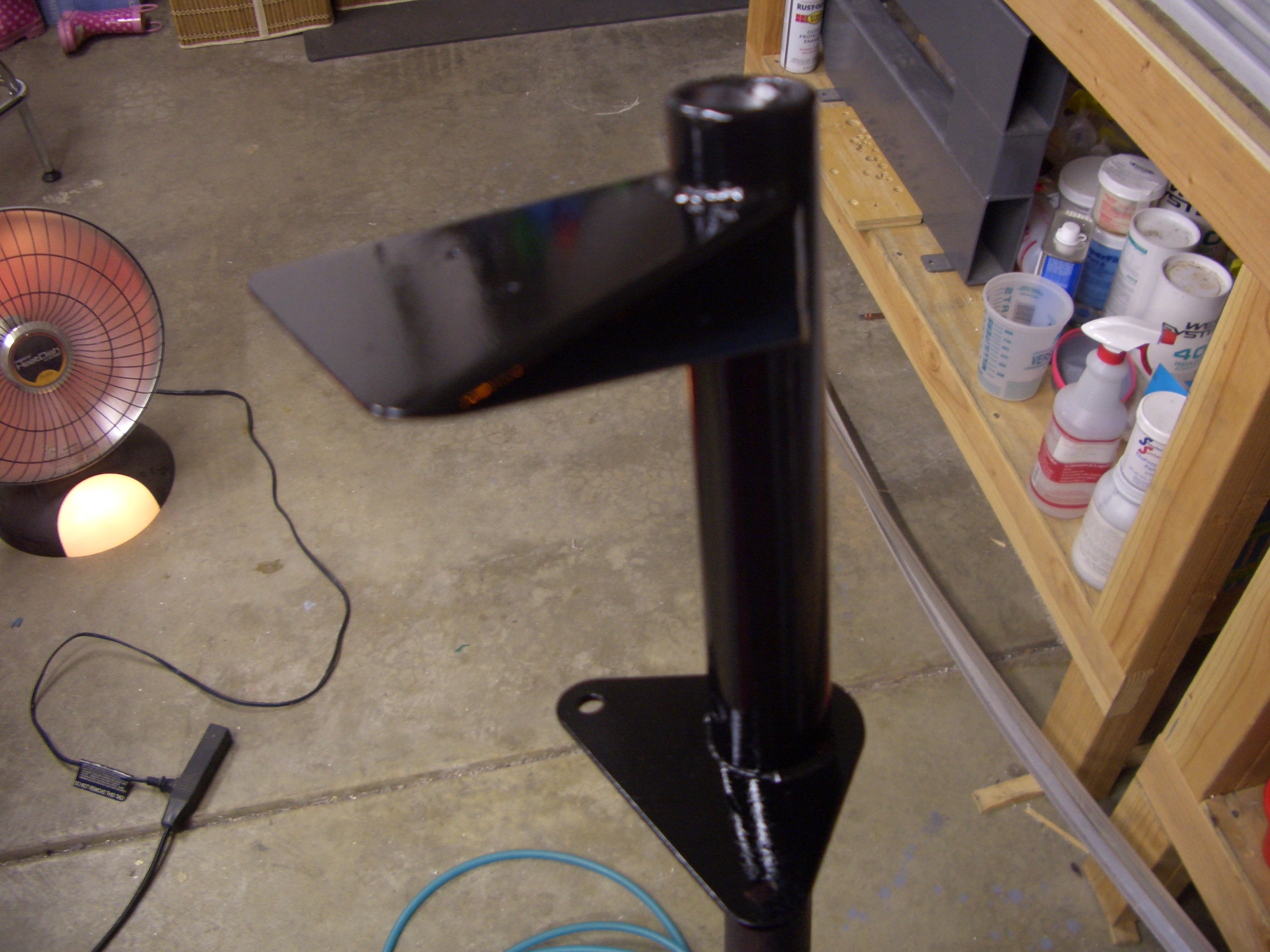
Primed Tailcone Stringers and Painted Tailwheel Spring Mount
I didn’t have a lot of time tonight, but I primed the stringers that I forgot to prime last night.
I also put a couple of coats of gloss black paint on the tailwheel spring mount to give it a little extra protection beyond the primer.
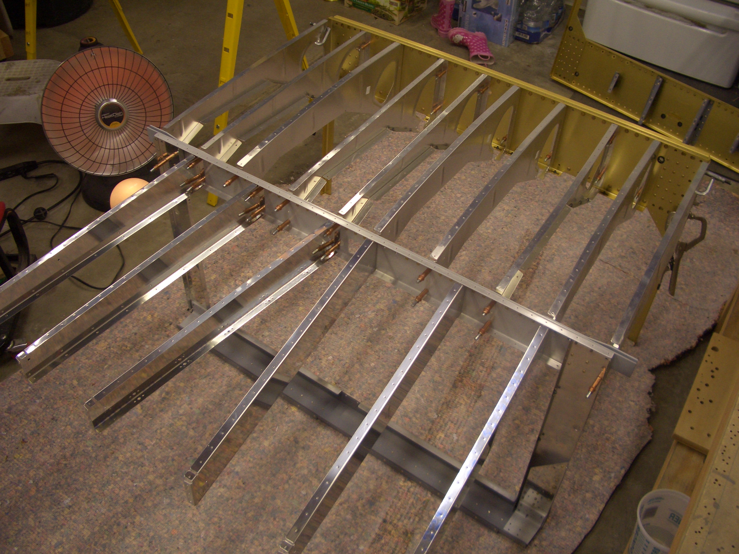
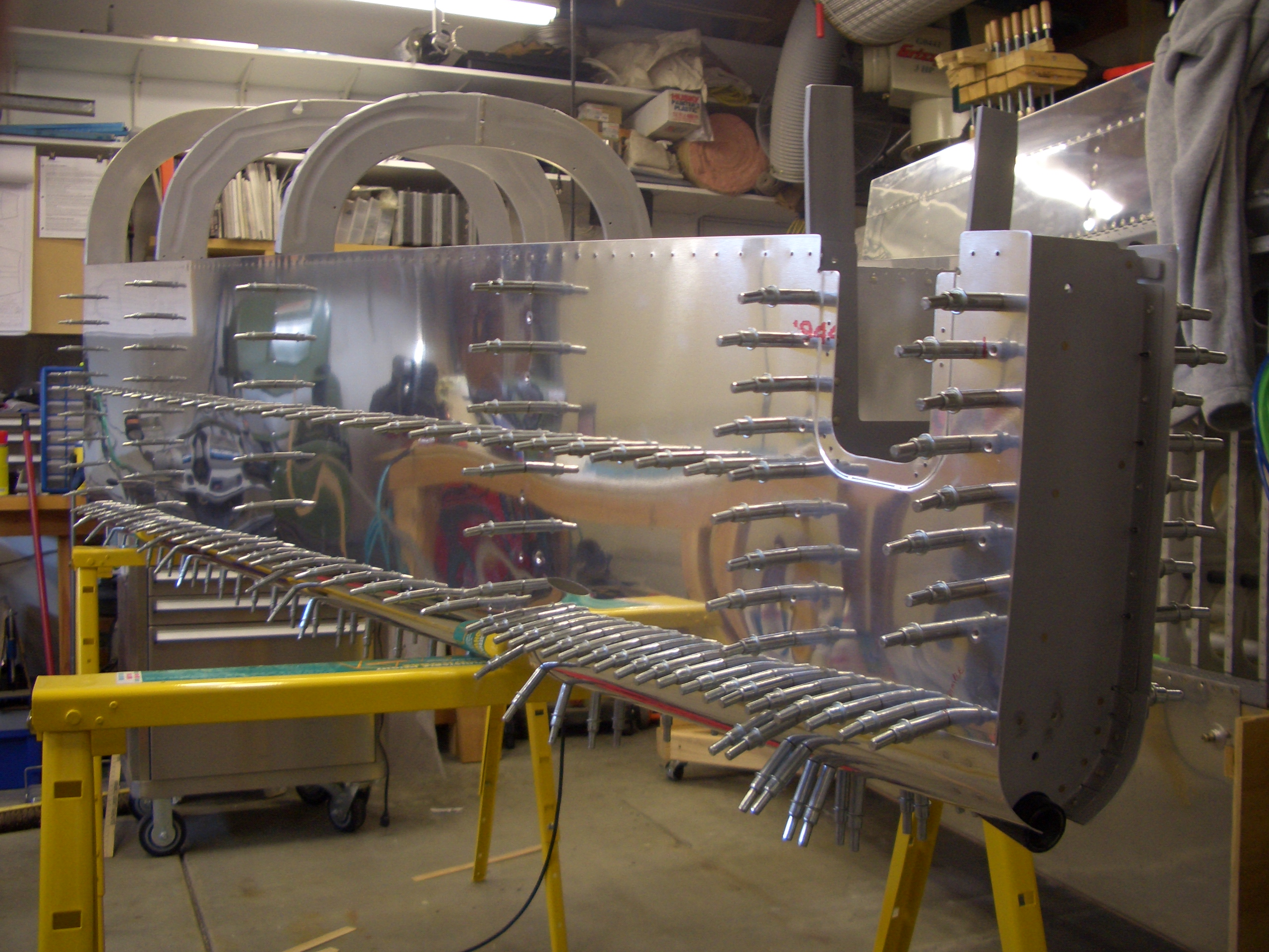
Assembled Tailcone and Started Riveting
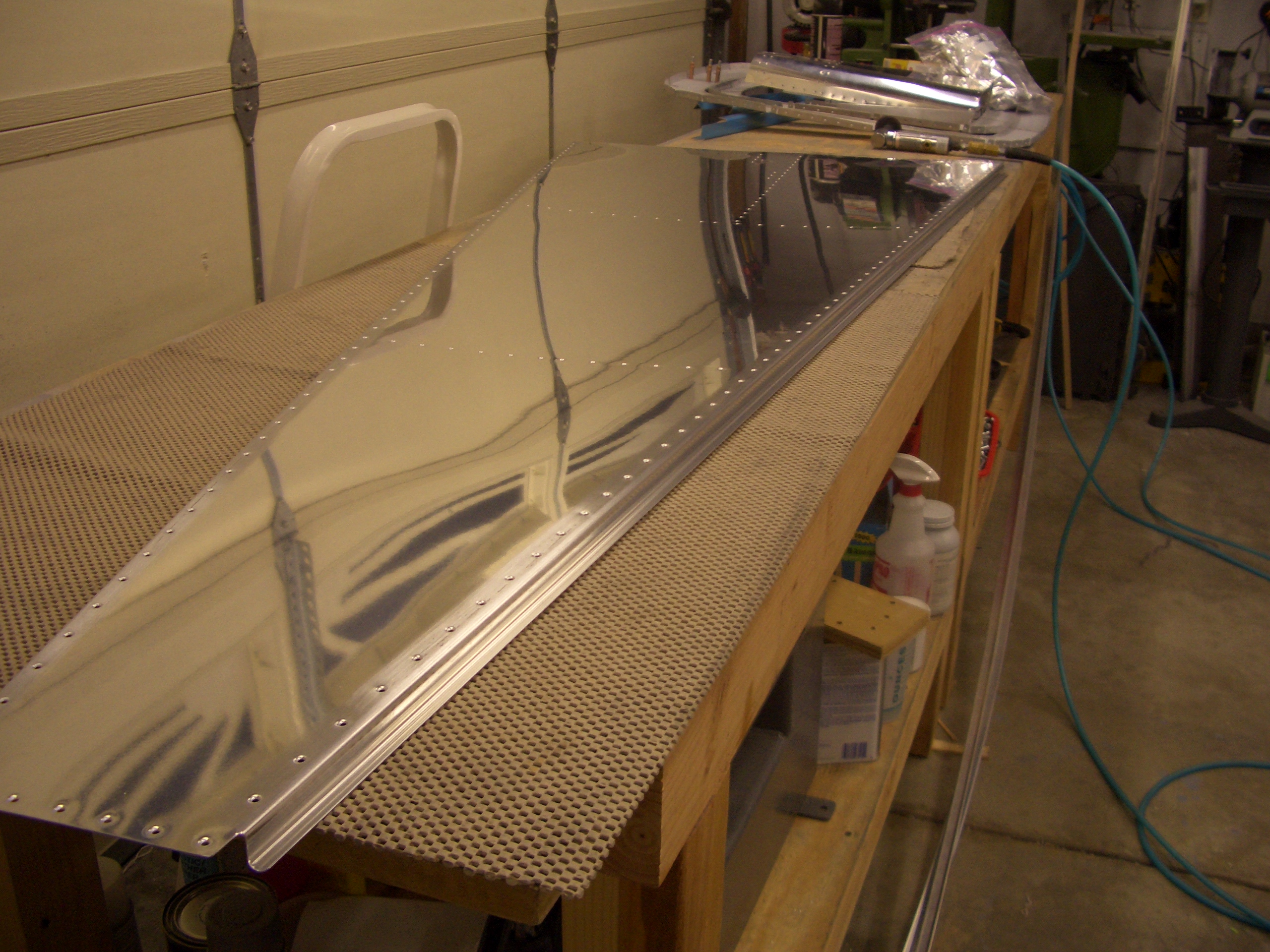
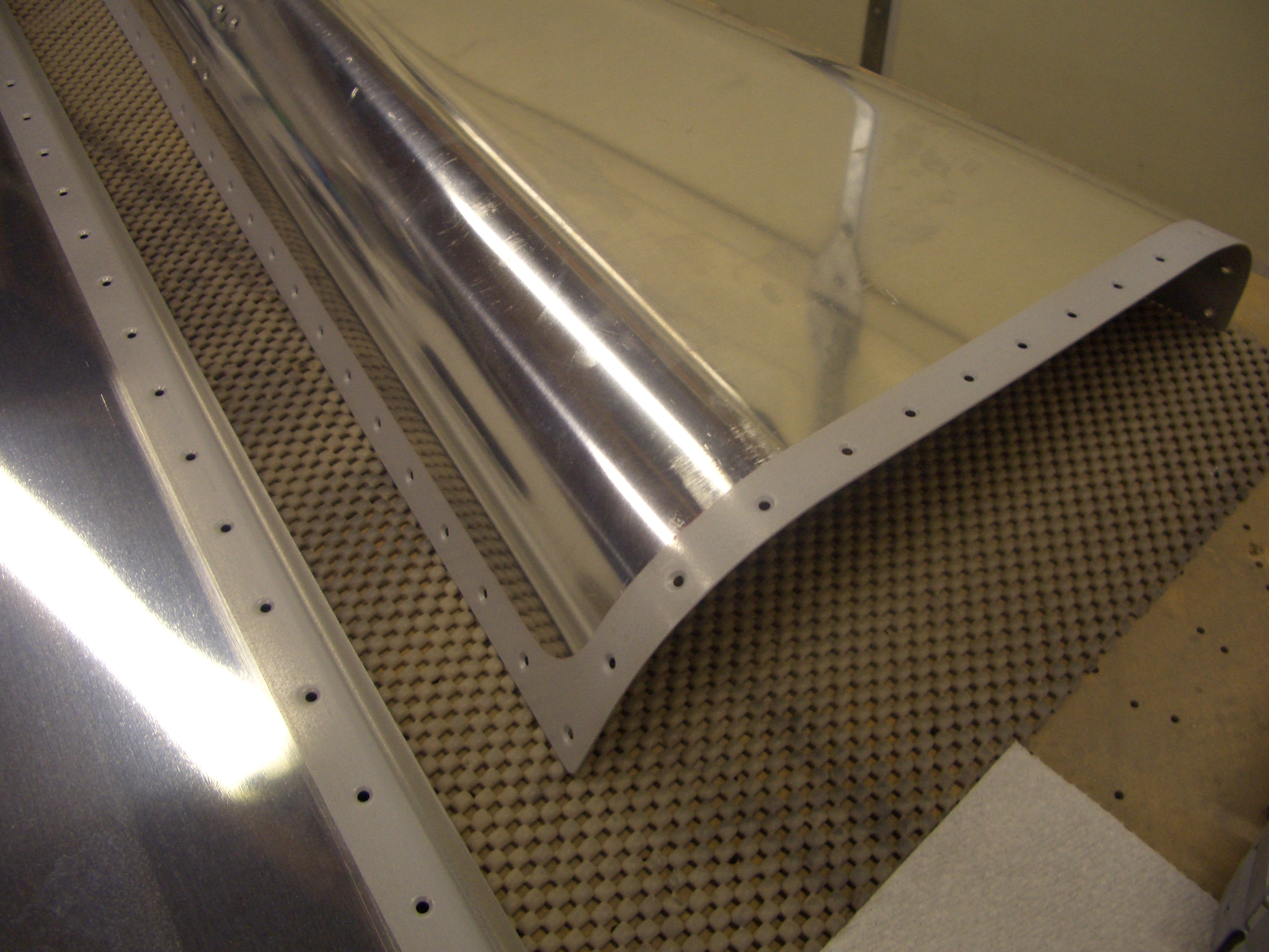
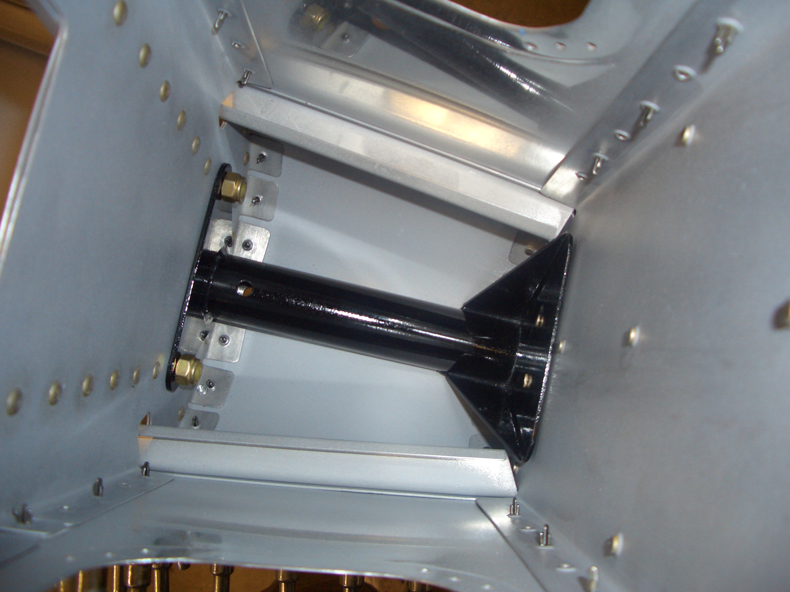
Now that everything in the tailcone is primed and the tailspring mount is painted, I clecoed the tailcone together.
The tailspring mount fits between F-711 and F-712. I shot and bucked the keeper rivets the hold the mount to F-712 (you can see them on the right side of the mount here. These just keep the mount from shifting until the bolts that tie this and the vertical stabilizer spar together are installed.
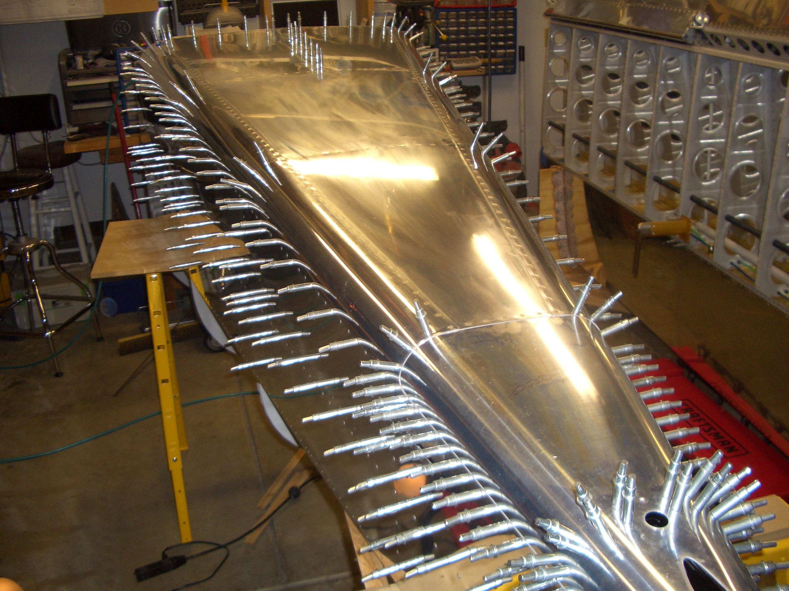
I flipped the tailcone upside down to make it more stable for riveting and shimmed it until there was no twist.
It was too late to run the rivet gun, but I squeezed all of the rivets in F-712 and all I could reach on F-711.
Worked on Longerons and Started Riveting Tailcone
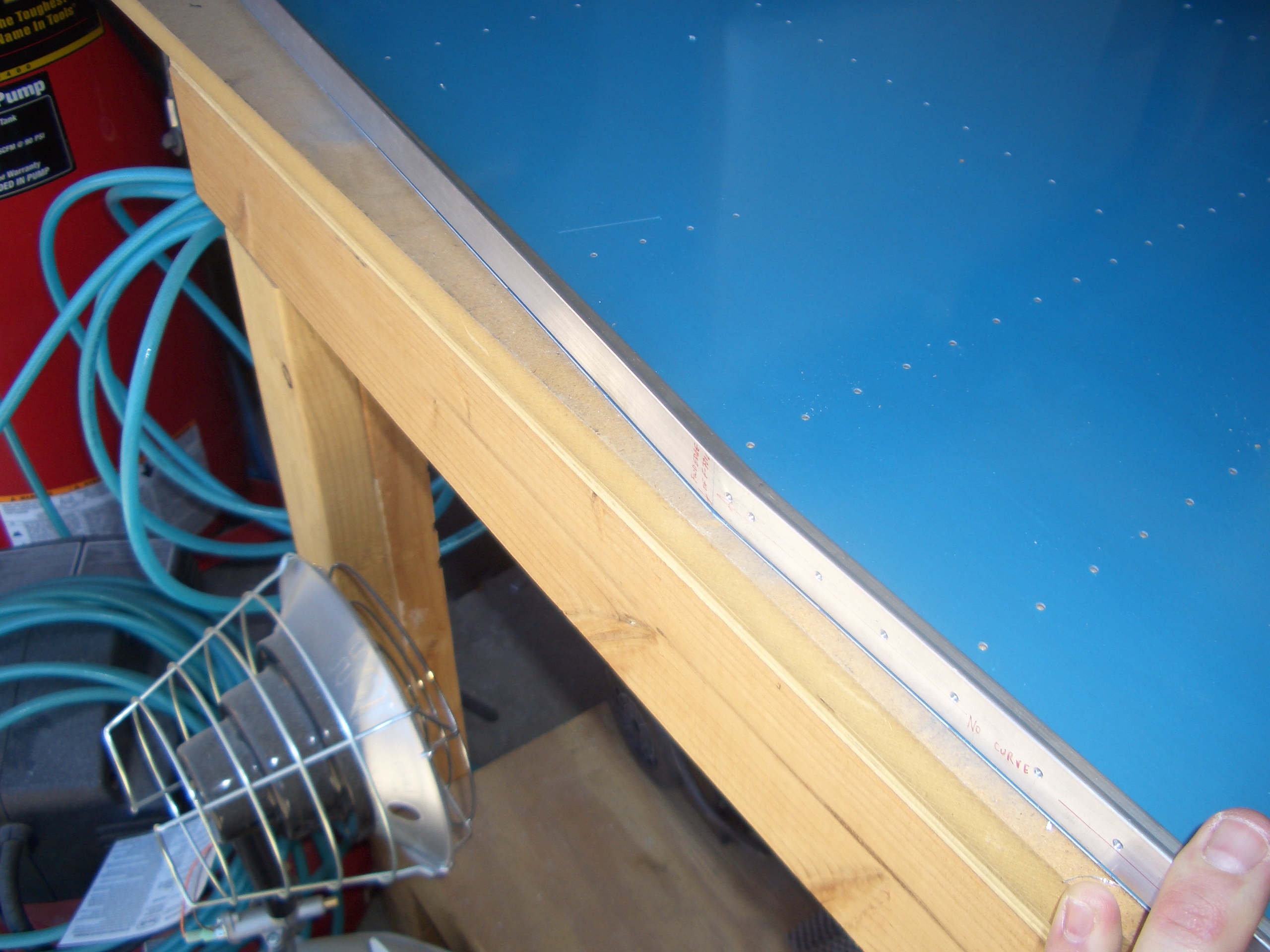
I finished the gentle curve in the left longeron and clamped some 0.032″ scrap to the side to simulate the side skin.
I then laid the left side rail in place and clamped it flush with the edge of the scrap (plus a little to account for material removal when edge finishing the side rail) and drilled it to the longeron.
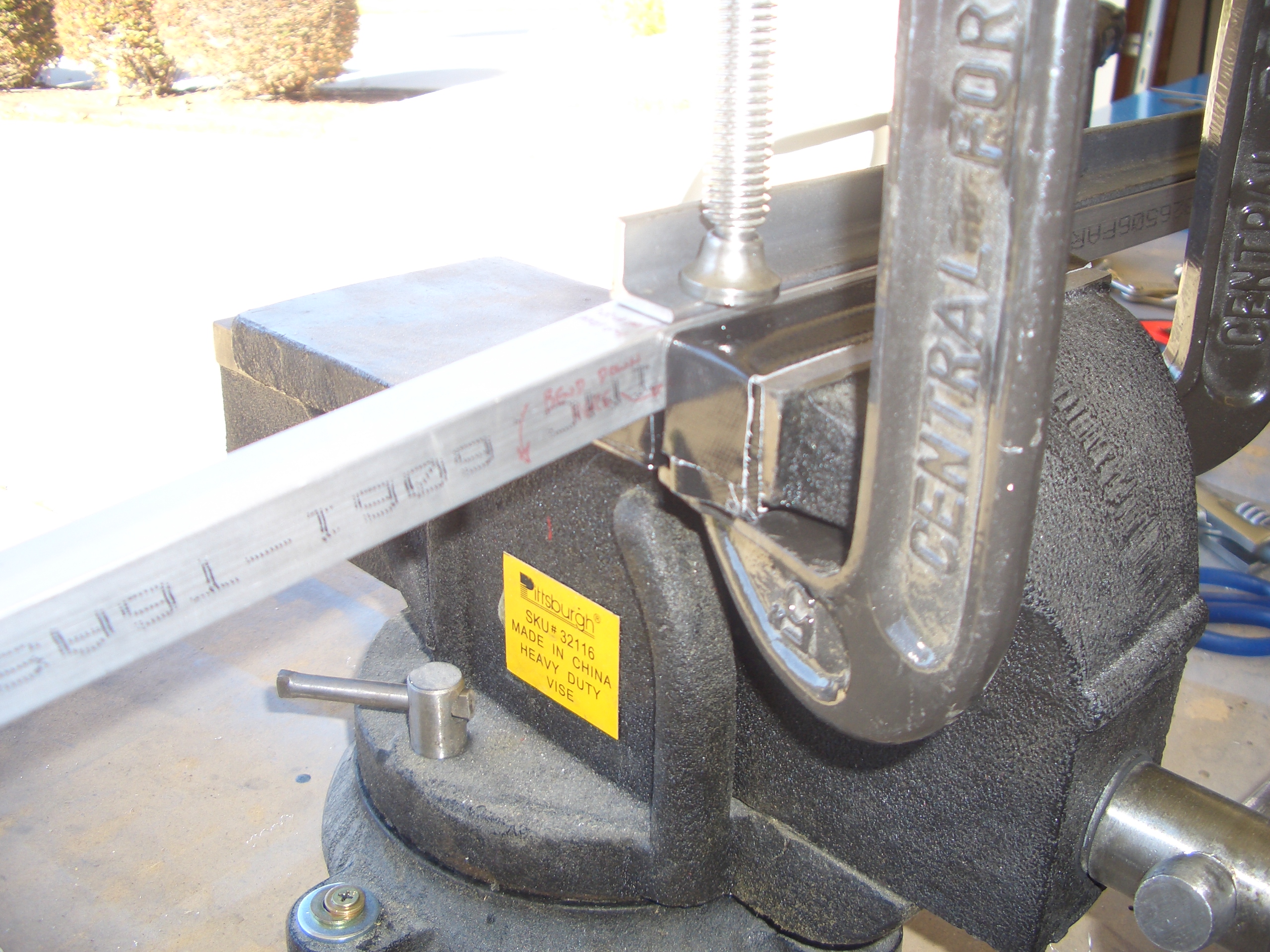
Next, I padded the jaws of the vise with some duct tape and clamped the longeron in place for the sharp downward bend 28 1/4″ after of the leading edge. I also clamped some scrap steel down to the top of the longeron to keep it from lifting as I perform the bend.
Here is the longeron after putting in the 5.6º downward bend.
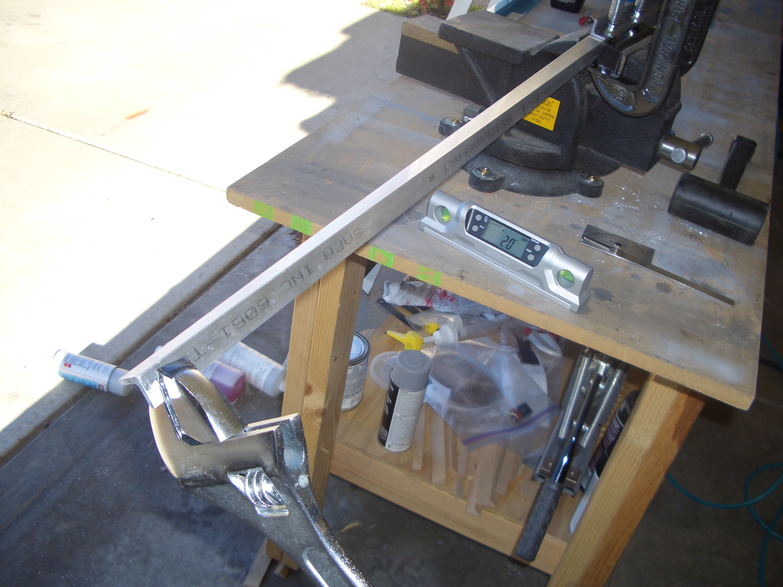
The longeron also needs a 17º inward twist from this point forward. I used a large crescent wrench to give this a healthy twist. You have to apply significantly more twist than you need to account for springback.
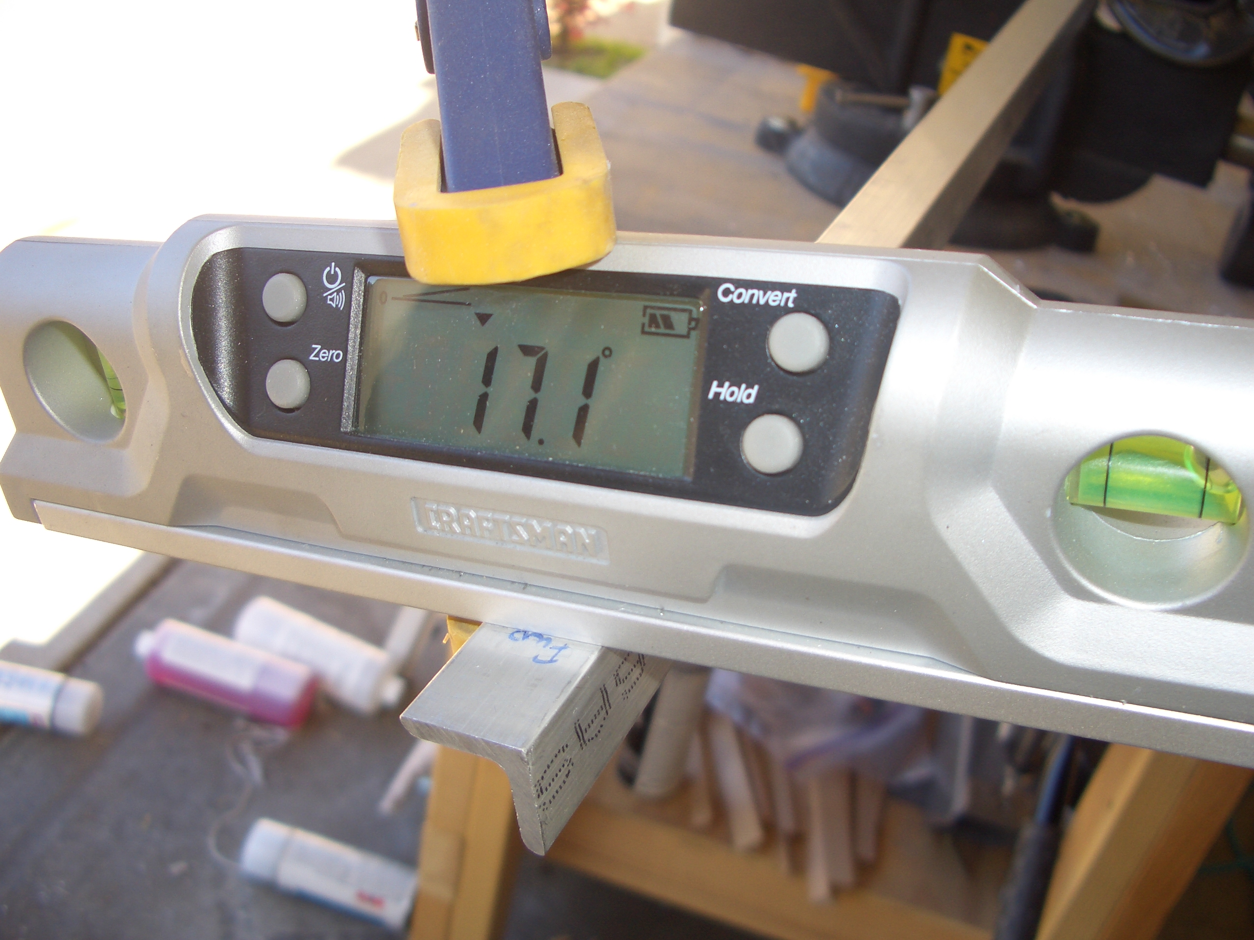
In the end, I got 17.1º. Clamping the longerons to the upper engine mounts will lock in the final angle.
Here you can see that the downward bend in the longeron lines up precisely with the cut in the side skin.
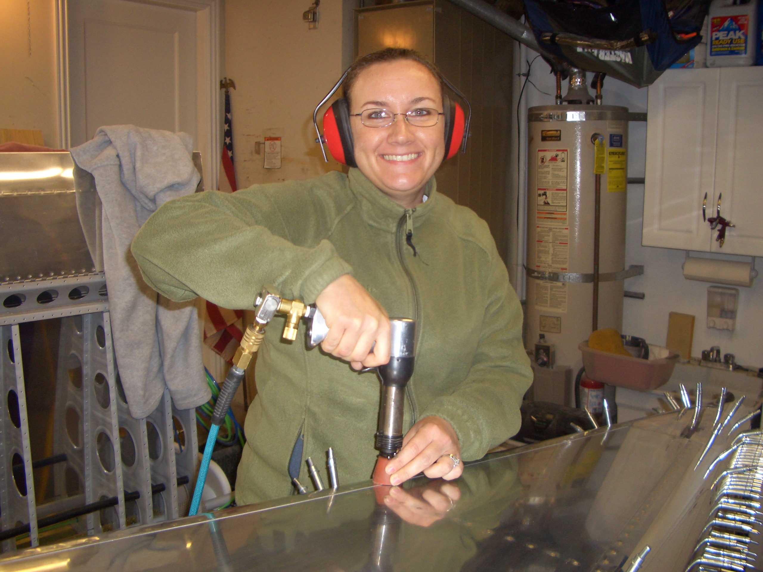
My wife Jenn graciously agreed to help me get started riveting the tailcone. Here she is manning the rivet gun.
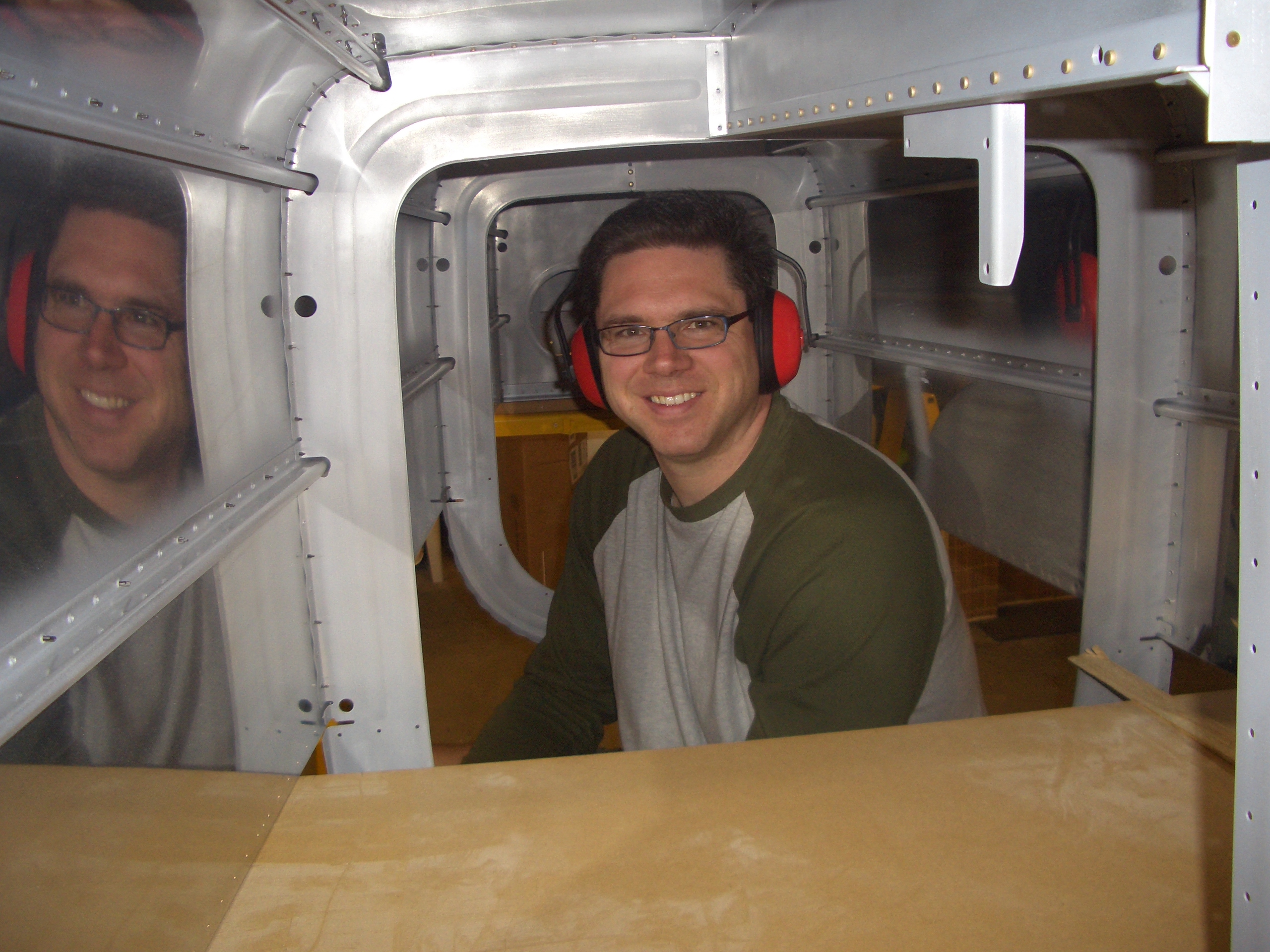
While I was sitting on a stool under the tailcone manning the bucking bar.
We got all of the rivets holding the bottom skin to F-707, F-708, and F-710 as well as the bottom skin to side skin joints. I still have to do the side skins to bulkheads and stringers as well as the rest of the rivets in F-711 and F-712 (the last two bulkheads).
Jenn really picked riveting up quick. Within just a few rivets, she was shooting them perfectly almost every time. I only had to drill out one rivet, and that was because I was holding the bucking bar slightly crooked. Like other builders, I had to upsize a few of the rivets by 1/2 size because the size specified on the plans was too short.
Before heading to bed, I finished up the gentle curve in the right longeron and match drilled it to the side rail. I’ll take care of the downward bend in the longeron tomorrow, then it’s on to the center section.
Started Center Section
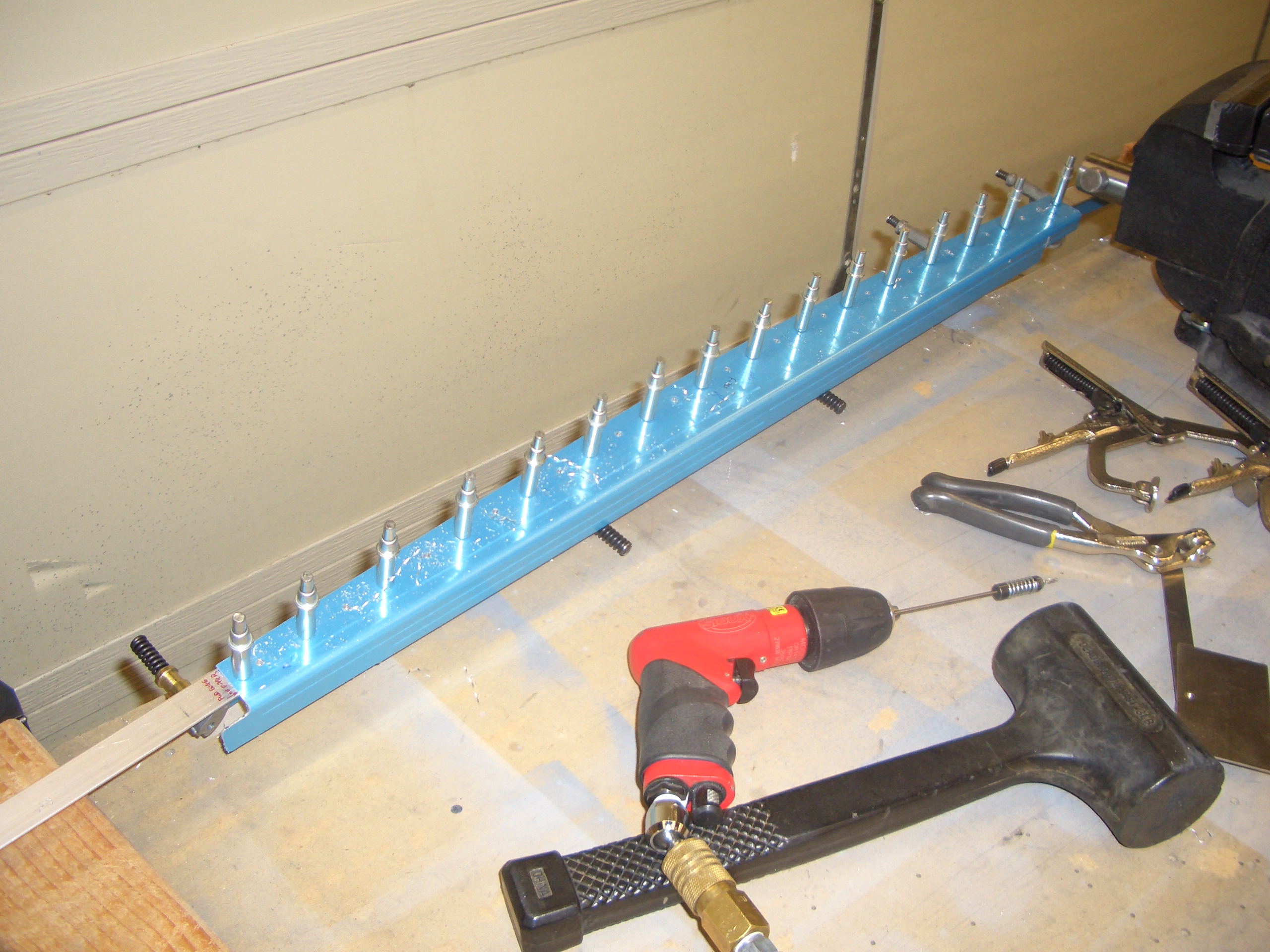
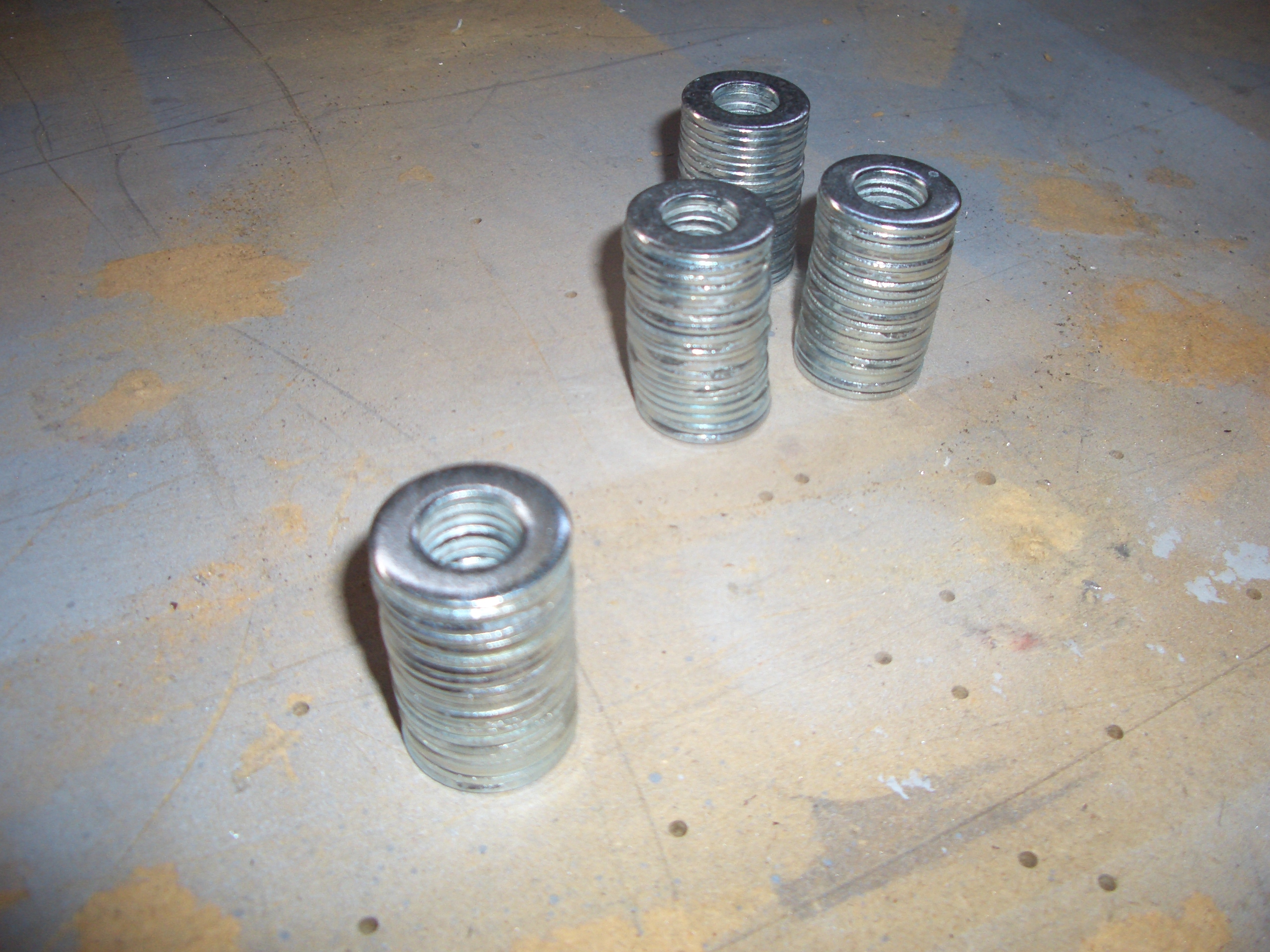
I started the center section tonight. This is the section containing the seats and the baggage area. First up is to fabricate the spacers that will keep the two halves of F-704 the proper distance apart so that the wing spars can slide in easily. The plans say to make these 1.438″ thick, but my spars were more like 1.441″, so that is the dimension I used. My method was to superglue a number of 7/16″ washers together until I had almost enough thickness and then use shims of aluminum tape to bring the spacers to within 0.001″ or so of the correct dimension (erring slightly over rather than slightly under).
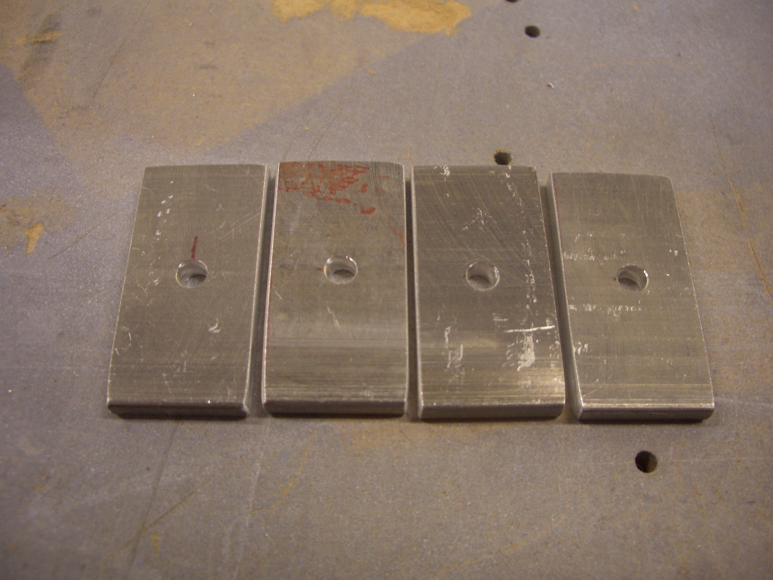
Next up was to fabricate some spacers from 1/8″ bar stock. These will fit between the center seat ribs and the rear spar.
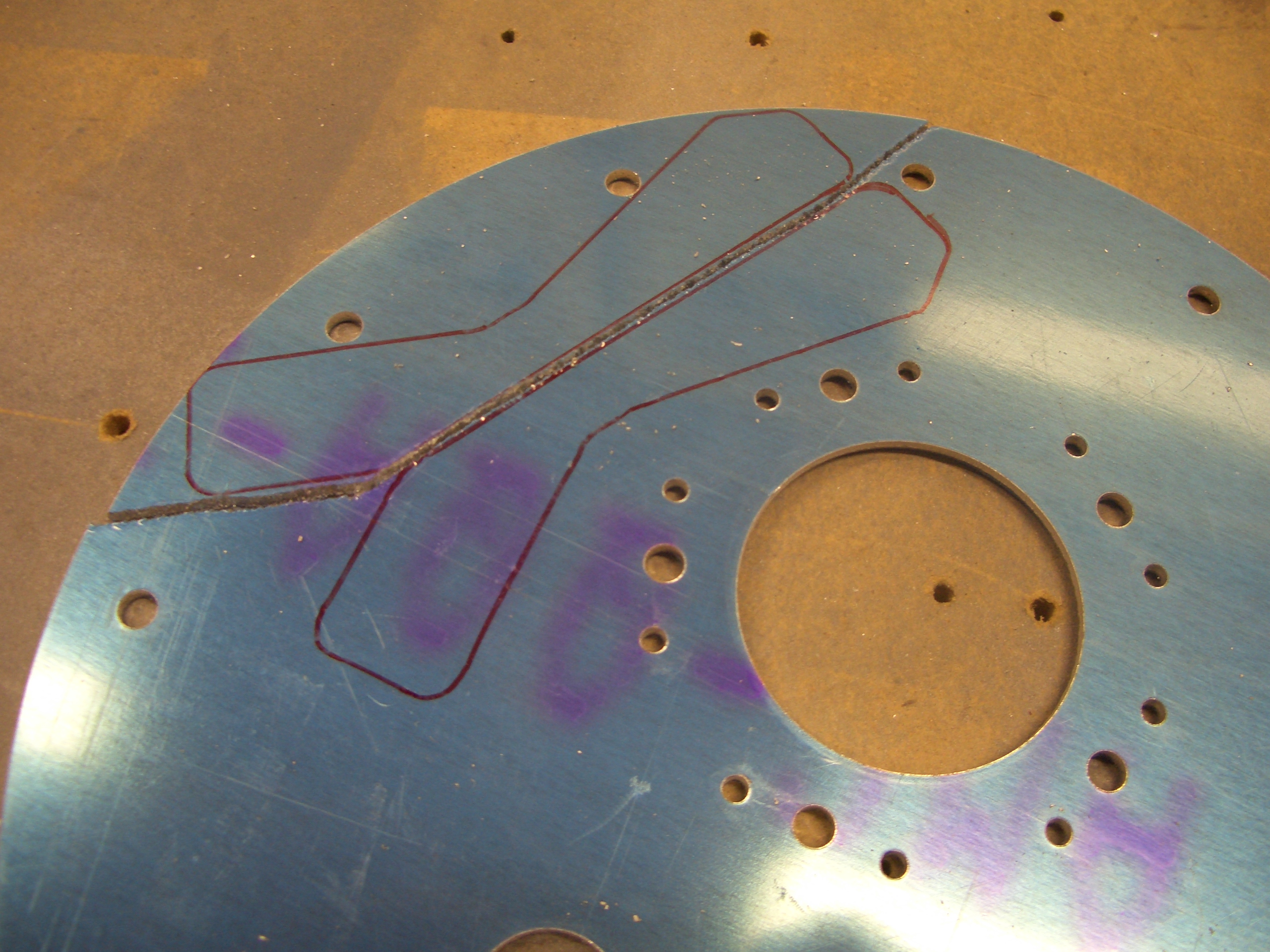
The plans have you modify the center two seat ribs with a small removable section so that the control center section can be removed. Many builders modify the center four ribs instead to make this task easier. The removable sections need clips that span the gap to retain the strength of the rib. These are pre-fabricated out of 0.063″ sheet, but the kit only provides two. The only extra 0.063″ sheet stock I had handy was the extra fuel tank access plates that are used when you’re not using flop tubes, so I traced the clips onto the plate and cut them out on the band saw.
After match drilling them to the existing clips, I clecoed all of them together and sanded them until the profiles matched.

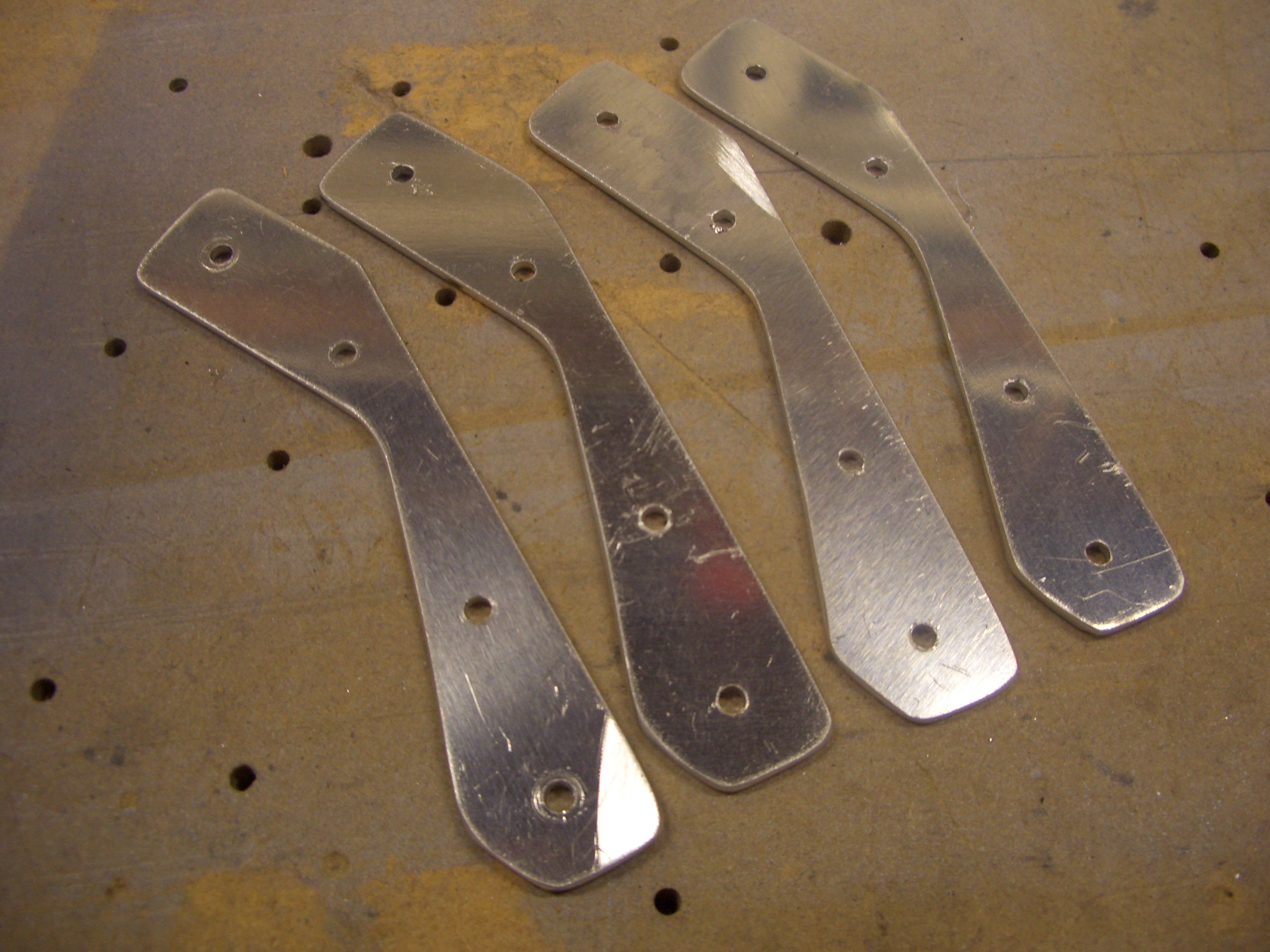
Here are the four clips, ready to be installed.
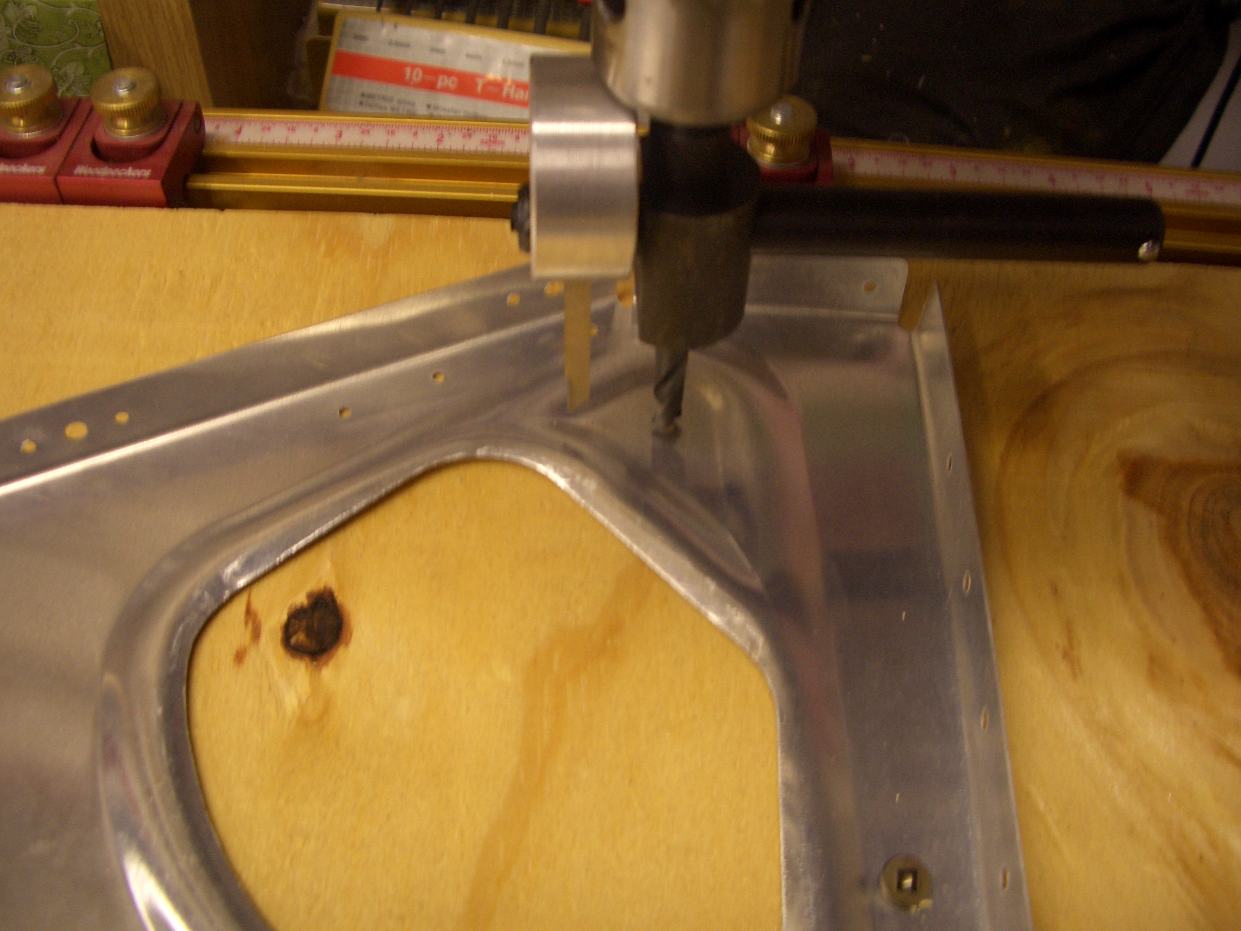
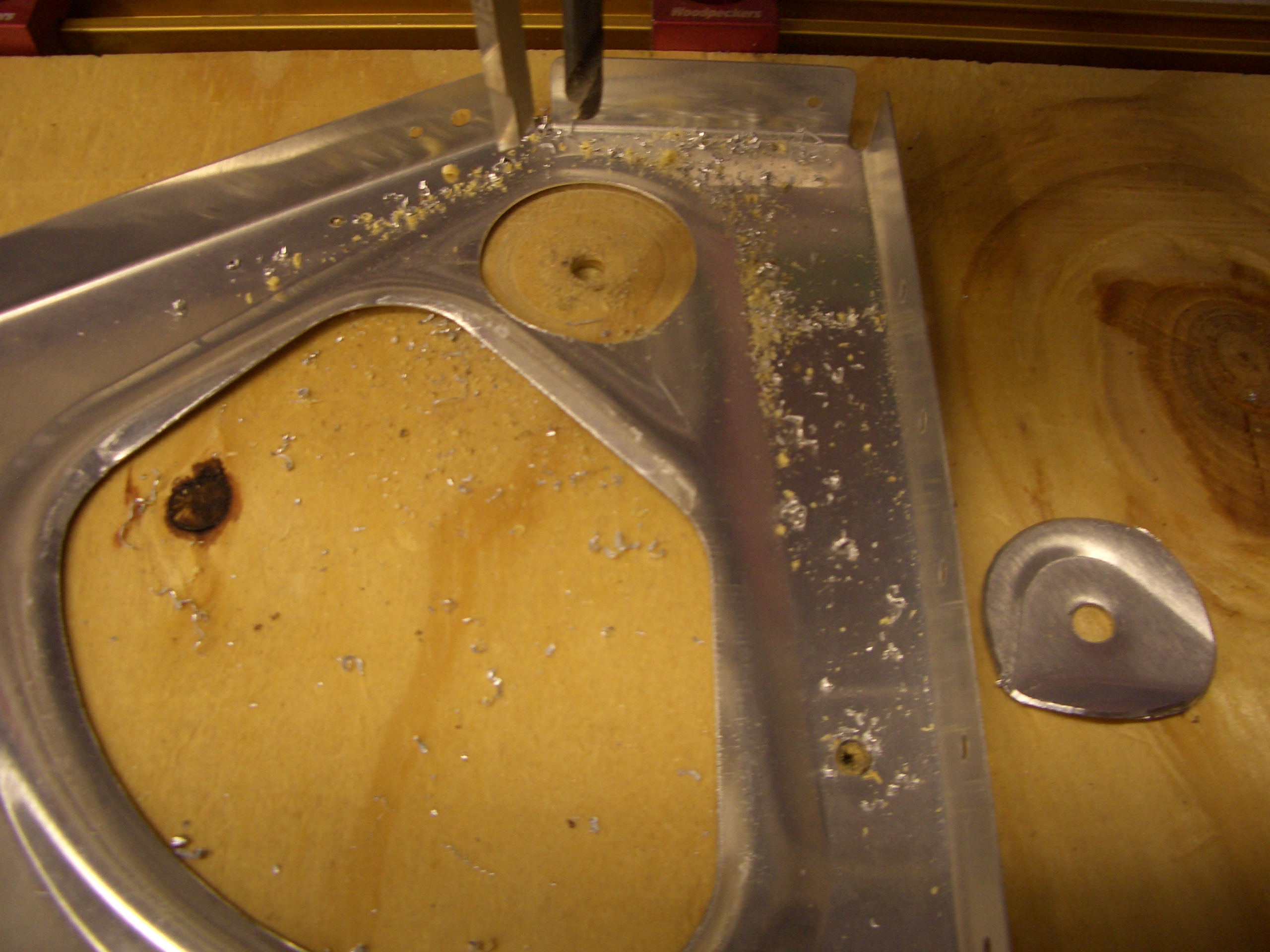
To modify the ribs, the first step is to cut a 1.5″ hole around the tooling hole already provided. I used my new Craftsman fly cutter and knocked these out in just a few minutes (the old Harbor Freight fly cutter was junk and this would have taken forever).
Here’s the result. The area between these two holes can now be trimmed out with some snips.
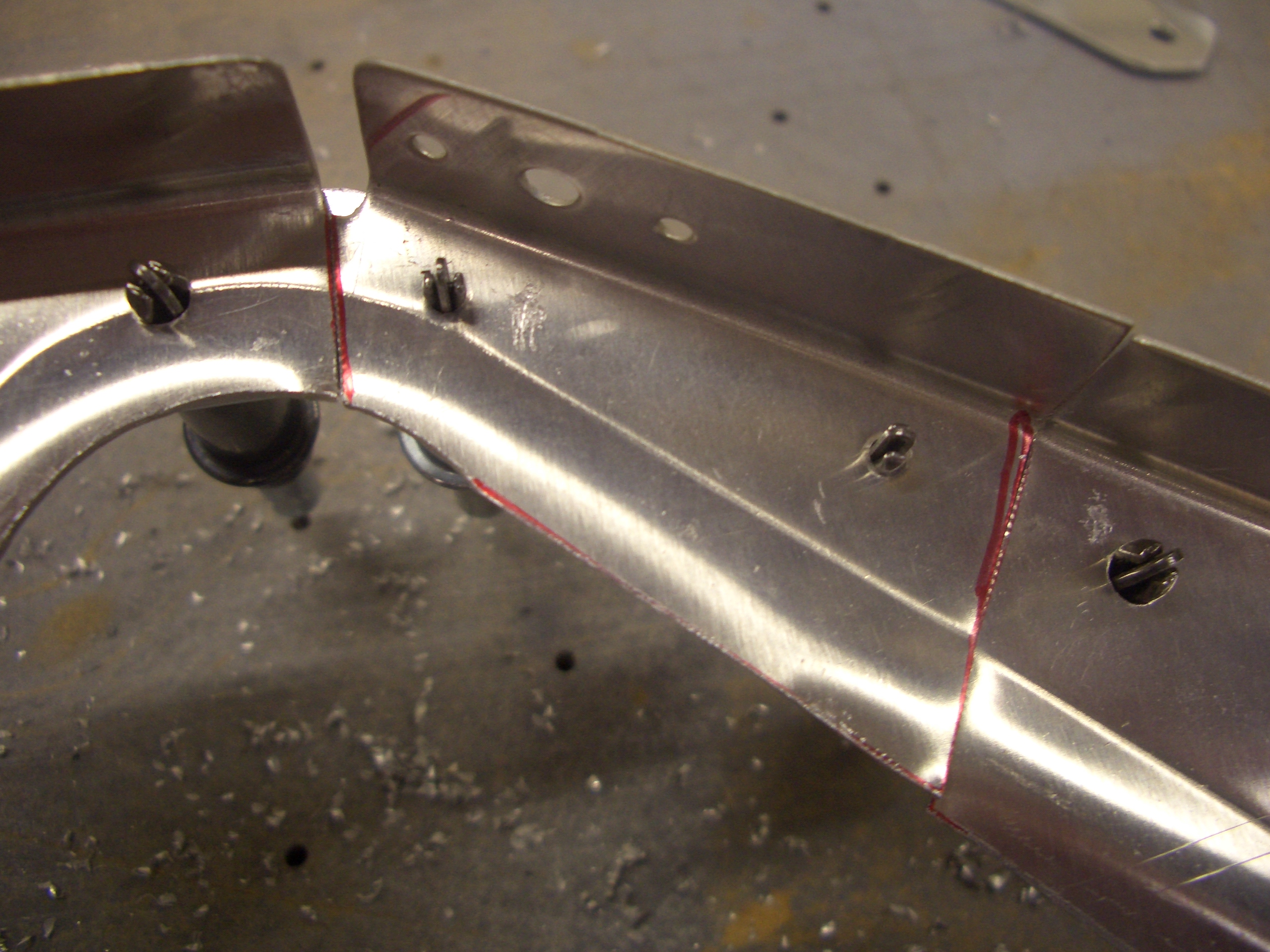
Next, a small portion near the top can be snipped out. Here it’s clecoed back in place to show how the retaining strap (on the other side) will span the gap.
Finally, a couple dozen platenuts need to be installed on the seat ribs so that the seat pan can be removed to access the controls.
I used to drill the center hole with a #19, cleco these in place, drive a screw in to make sure it was aligned with the hole and held firmly, then match drill the skin through the platenut to make sure the rivet holes were perfectly inline. After deburring and countersinking, I would then put the screw back in to ensure the platenut was still aligned with the hole.
I think this is significant overkill though Given the accuracy of these pre-punched kits, the holes are already exactly in the right spots, and drilling these out can’t move the hole significantly. So tonight I tried something a little simpler. I drilled the center holes out to #19 and the side holes out with #40, all without attaching the platenut. After deburring and countersinking the rivet holes for NAS1097 rivets, I riveted the platenut in place without putting a screw in. Every single one came out perfect. This is going to make installing platenuts significantly faster from here on out.
It was late, but I wanted to cleco the center section together tonight to see what it looked like. First up is to cleco all of the seat ribs to the aft portion of F-704.
The baggage ribs are clecoed to the aft side of F-705.
Finally, the two sections can be joined. It was at this point I noticed that I forgot to flute the ribs (it’s nearly 1 am, so I’m obviously getting a bit tired). This seems like a good stopping point for the night. I’ll flute these ribs and proceed from here tomorrow.