Bent Upper Seat Adjustment

A couple of pieces of the upper seat adjustment mechanism needs to be bent to 4º.  I tried this without a brake and the bend was pretty poor.  I took advantage of the black friday sale at Harbor Freight to pick up this brake and made perfect bends in just a couple of minutes.

Upper Seat Back Adjustment

I drilled the upper seat back adjustment pieces.  None of these pieces have any layout holes, so everything has to be measured and drilled.

These pieces allow you to position the upper seat back in two forward positions by sliding the edge of part of the seat back into one of the two slots defined by these pieces.  Here, the seat back piece is positioned in the forward position.

Prepped, Primed and Riveted Bulkheads

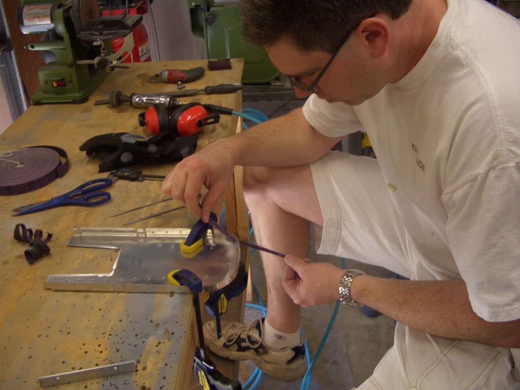
The bulkheads have a bunch of separate flanges because of the tight radius of some of the curves.  Some emery cloth cut into 1/4″ wide strips works pretty sell when used like dental floss.

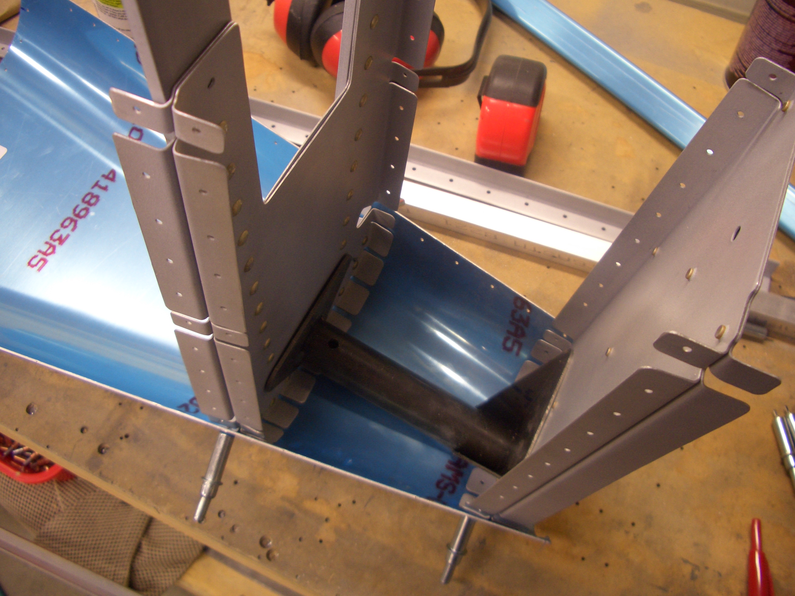
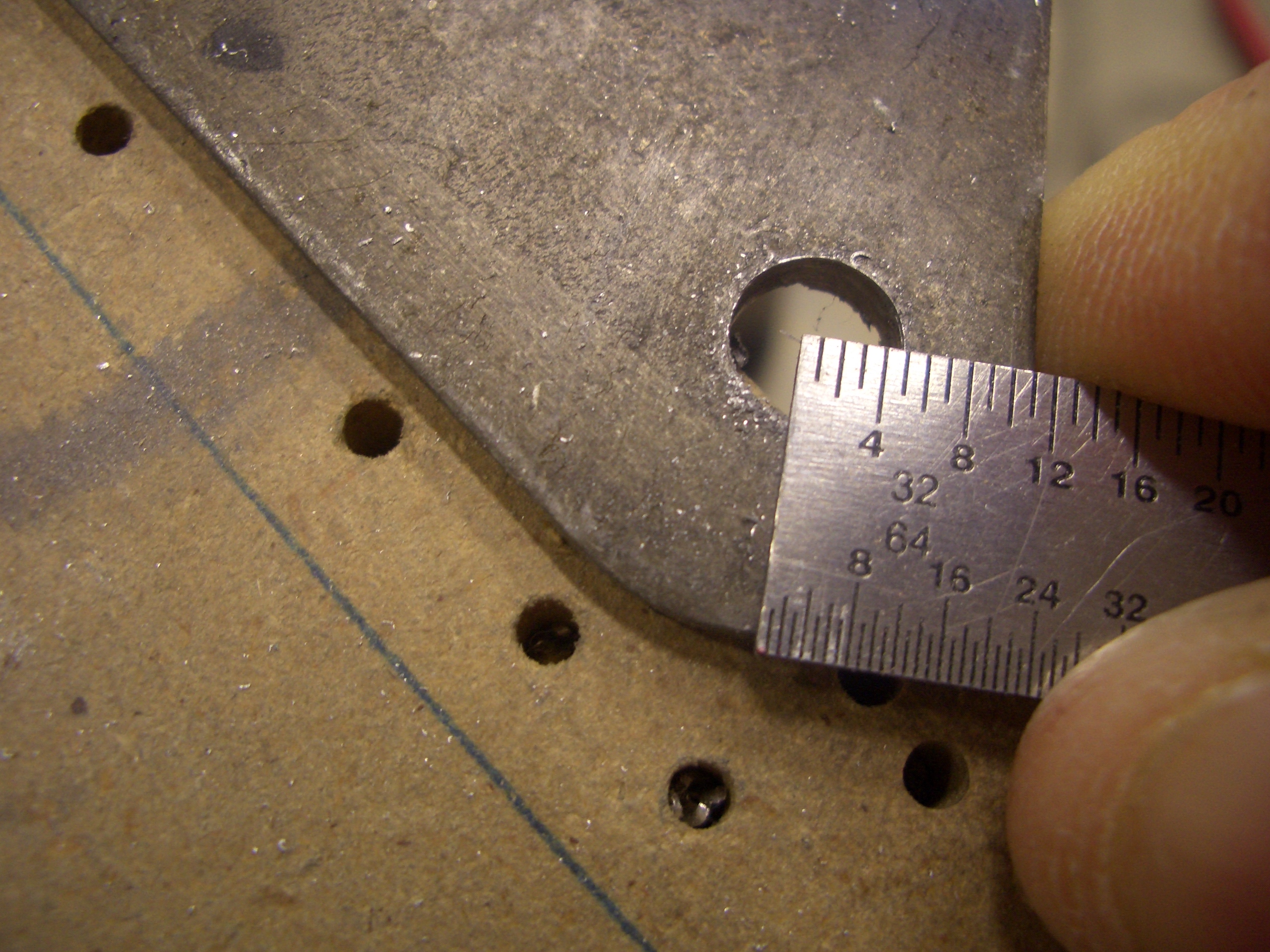
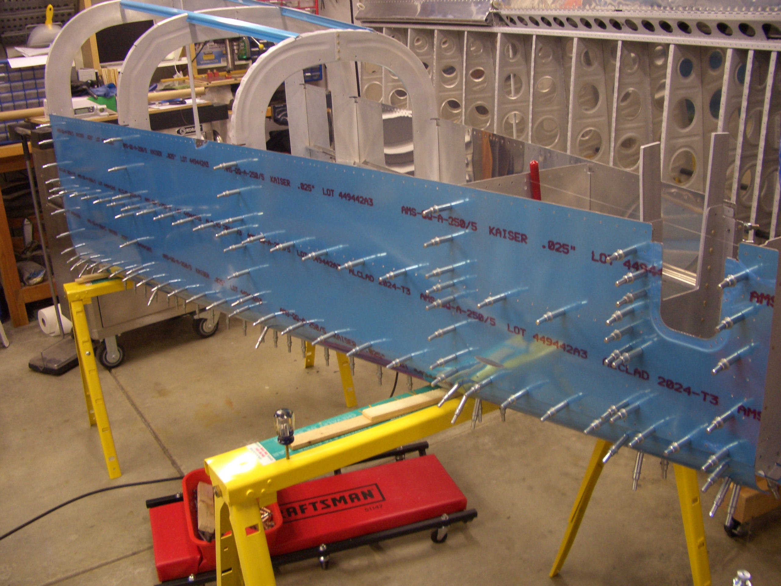
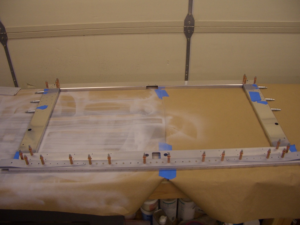
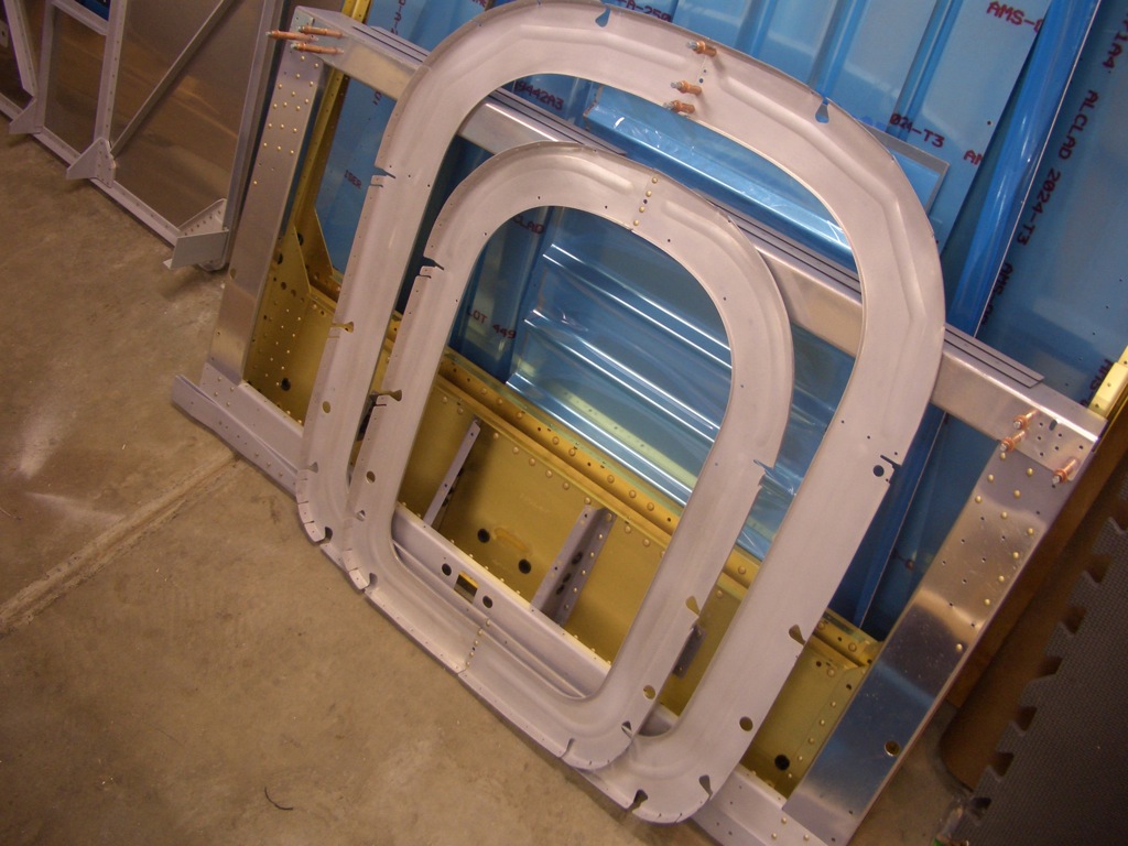
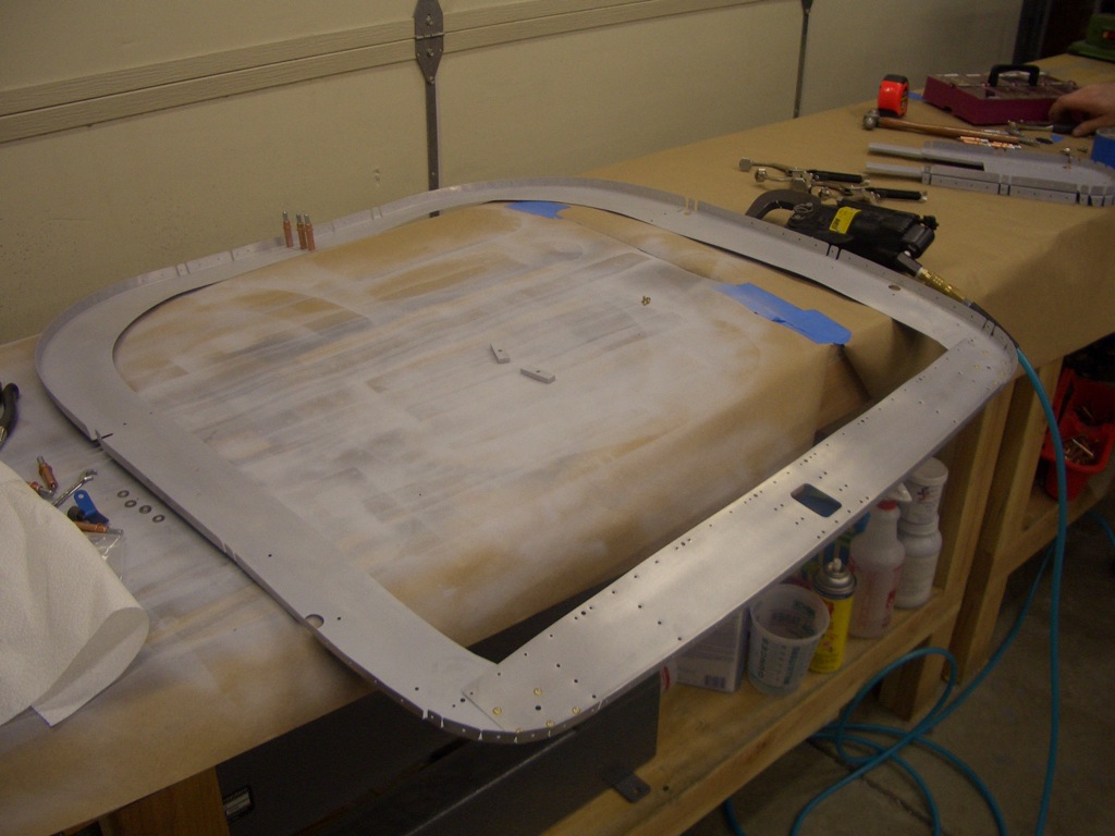
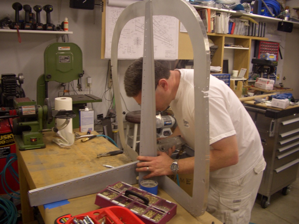
After a lot of sanding, cleaning and priming, the bulkheads are starting to go together.  Here, the F-705 bulkhead is clecoed together.  Double check that this bulkhead is square before riveting since the clecos allow some play in these pieces.  I could change the diagonal measurement as much as 1/4″ by racking these pieces from side to side.  After assuring that everything is square, this can be riveted together.  The blue tape signifies the holes that need to be left open right now since they will be riveted together with other parts of the structure at a later time.

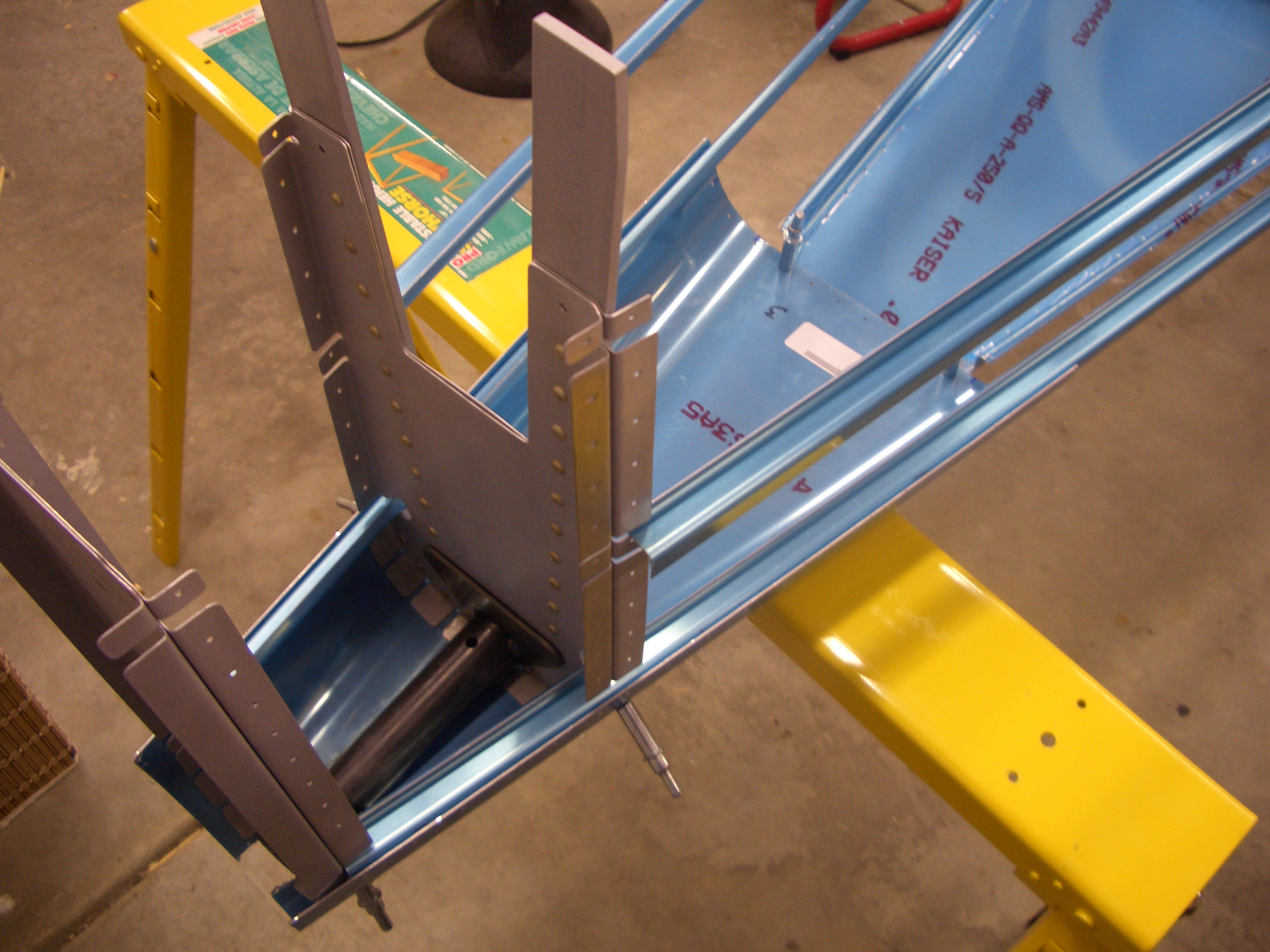
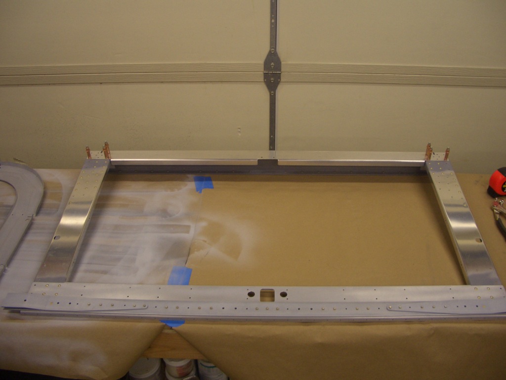
Here is the F-705 bulkhead riveted together.  The clecos near the top are there because these pieces are riveted in conjunction with other parts.

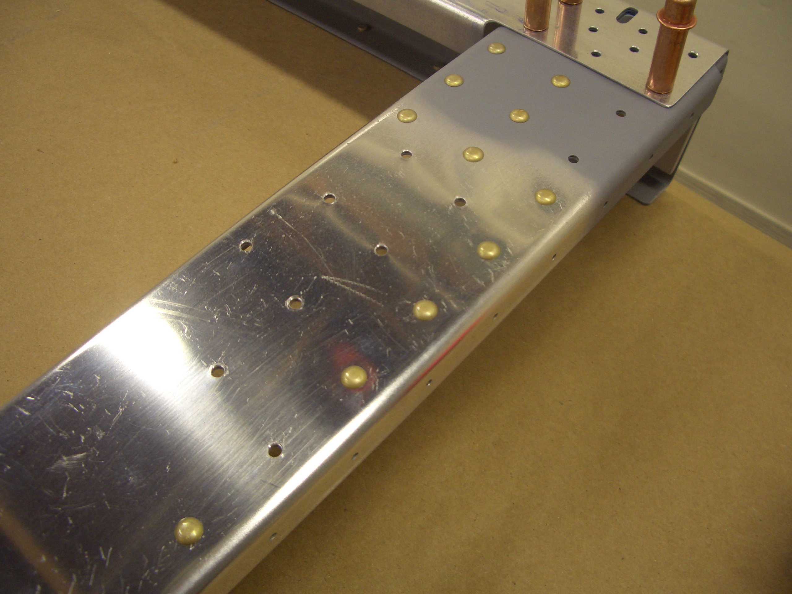
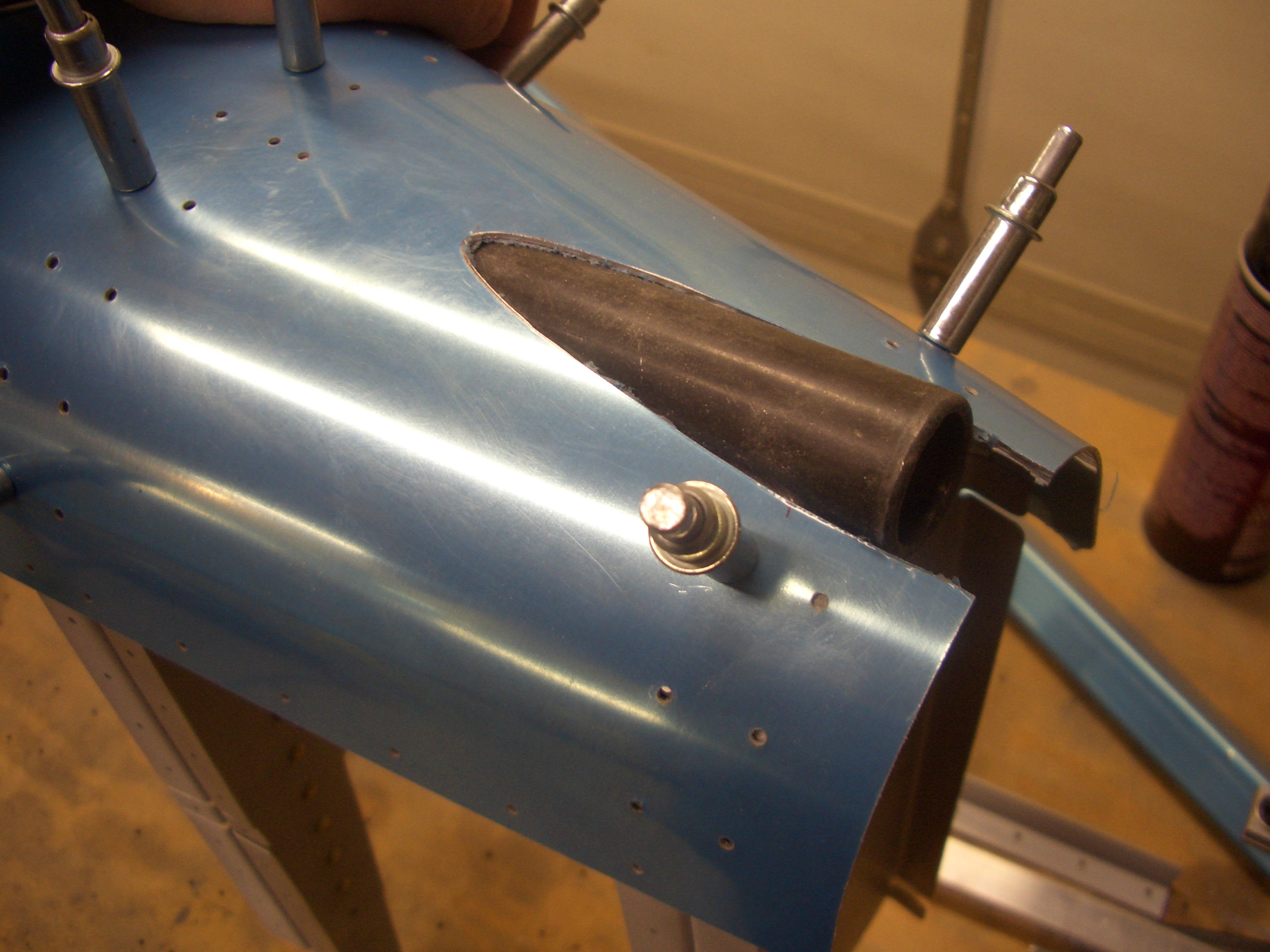
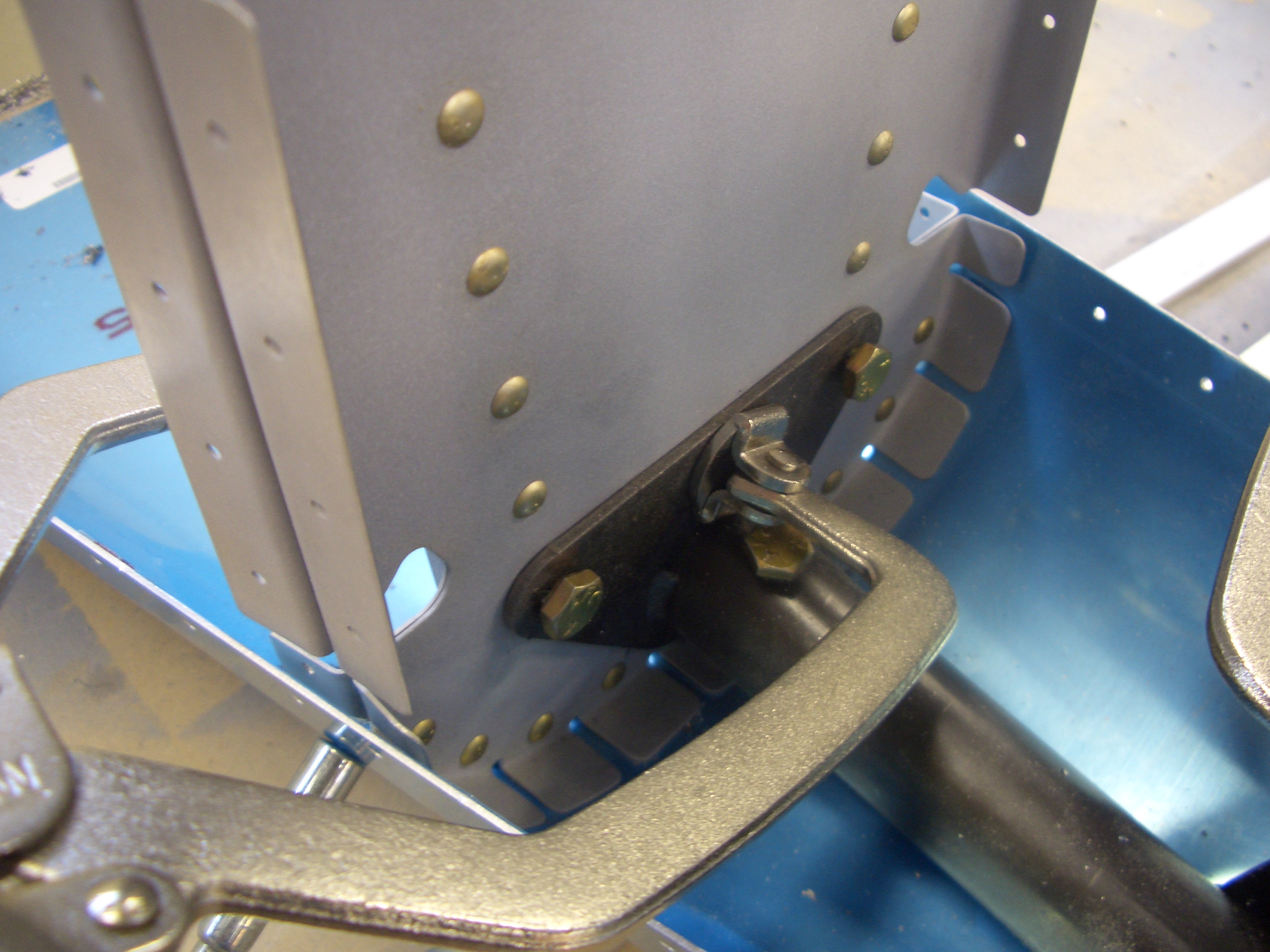
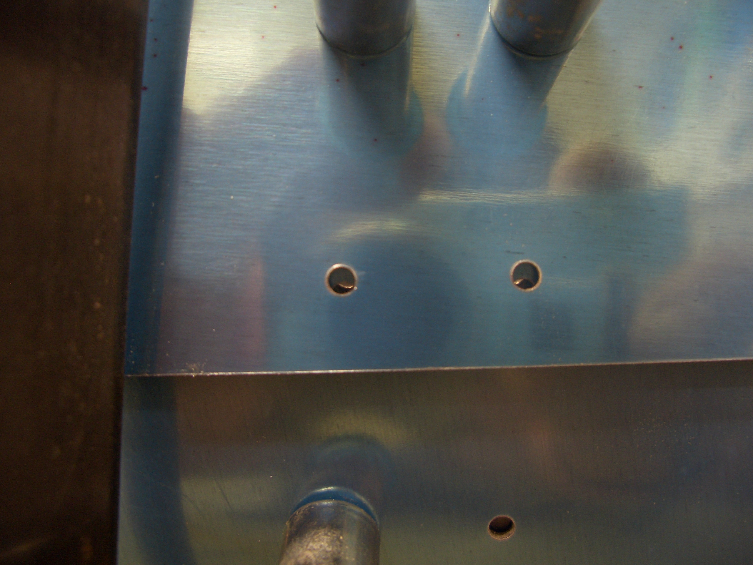
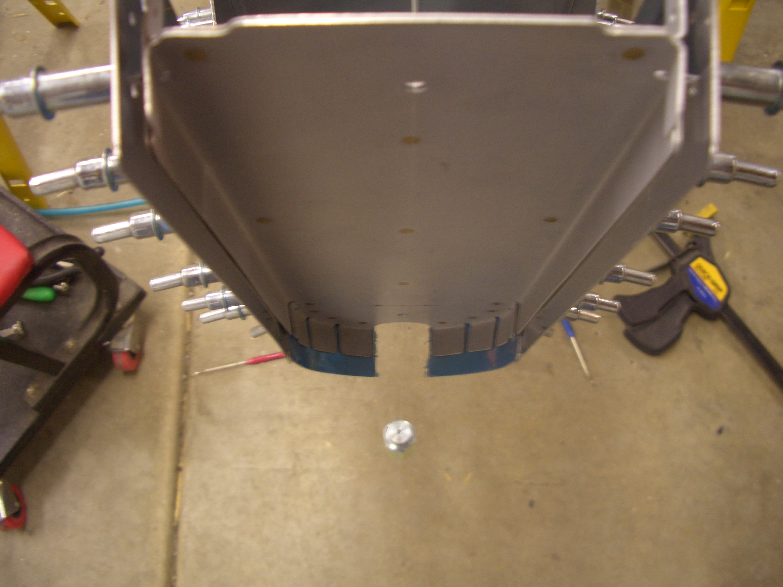
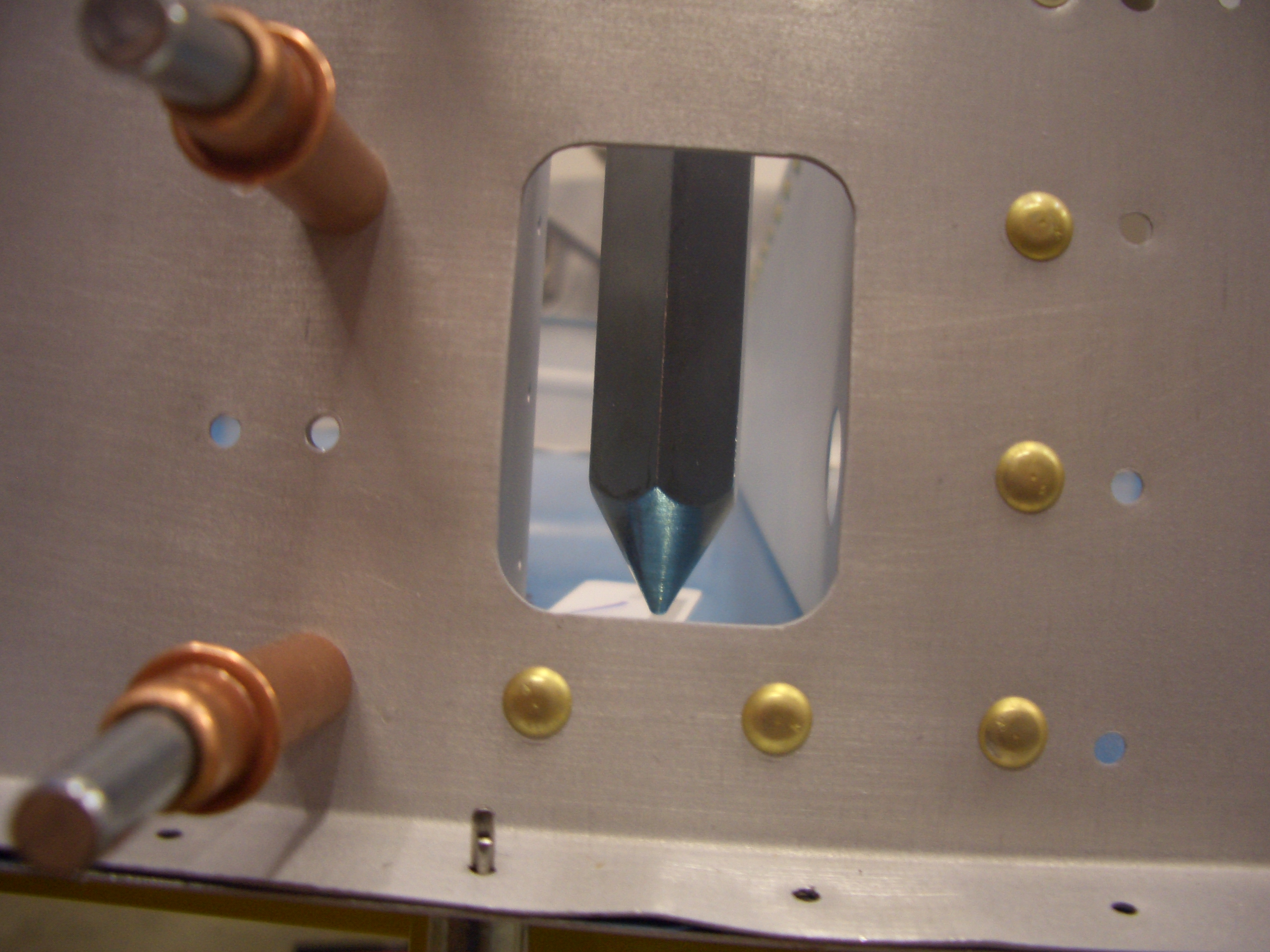
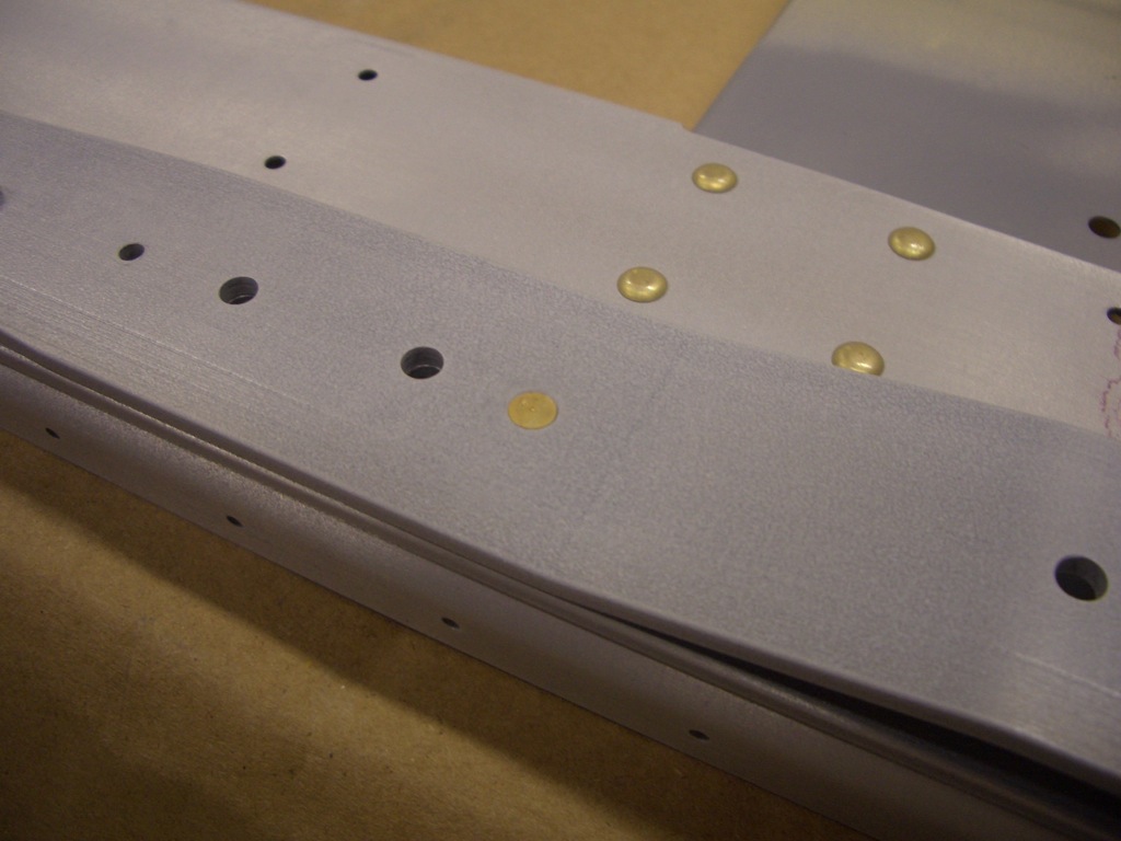
This rivet needs to be a flush head since the seat belt attach anchor extends past this point.

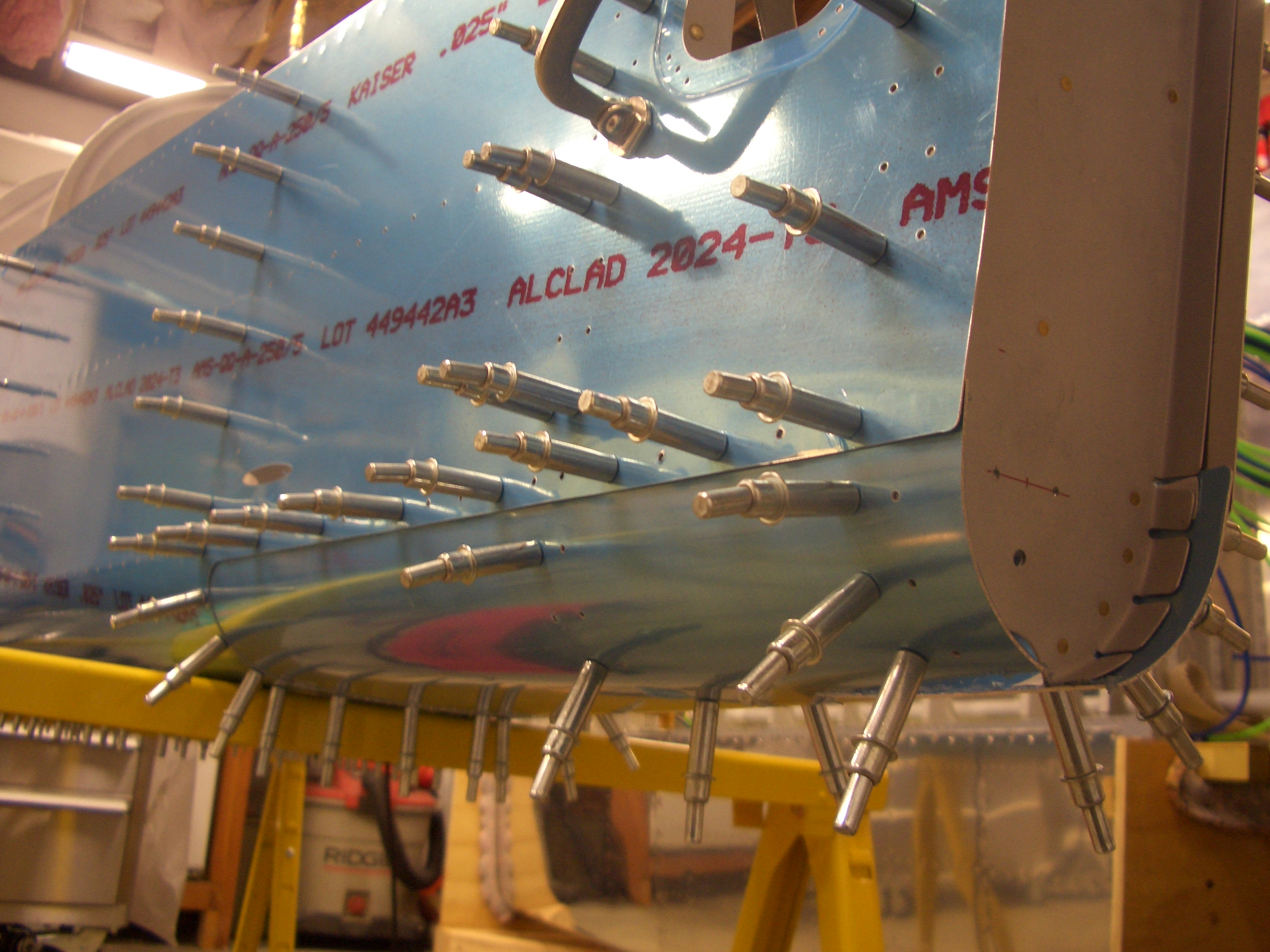
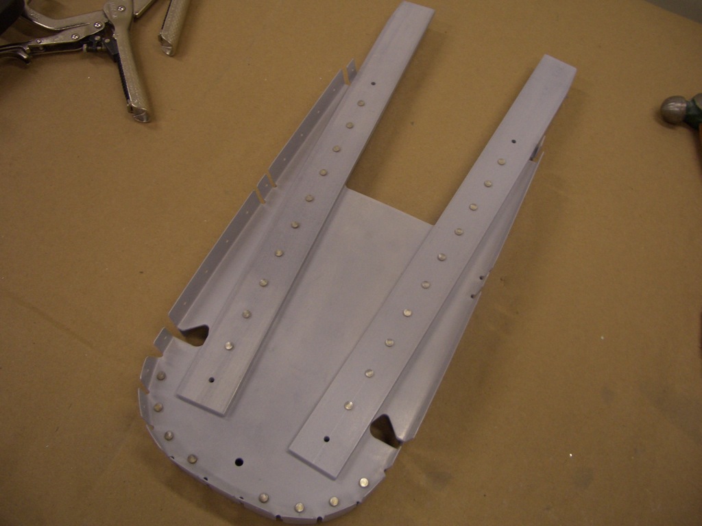
Here is a closeup of the upper left portion of the F-705 bulkhead showing how many holes need to be left open for later riveting.

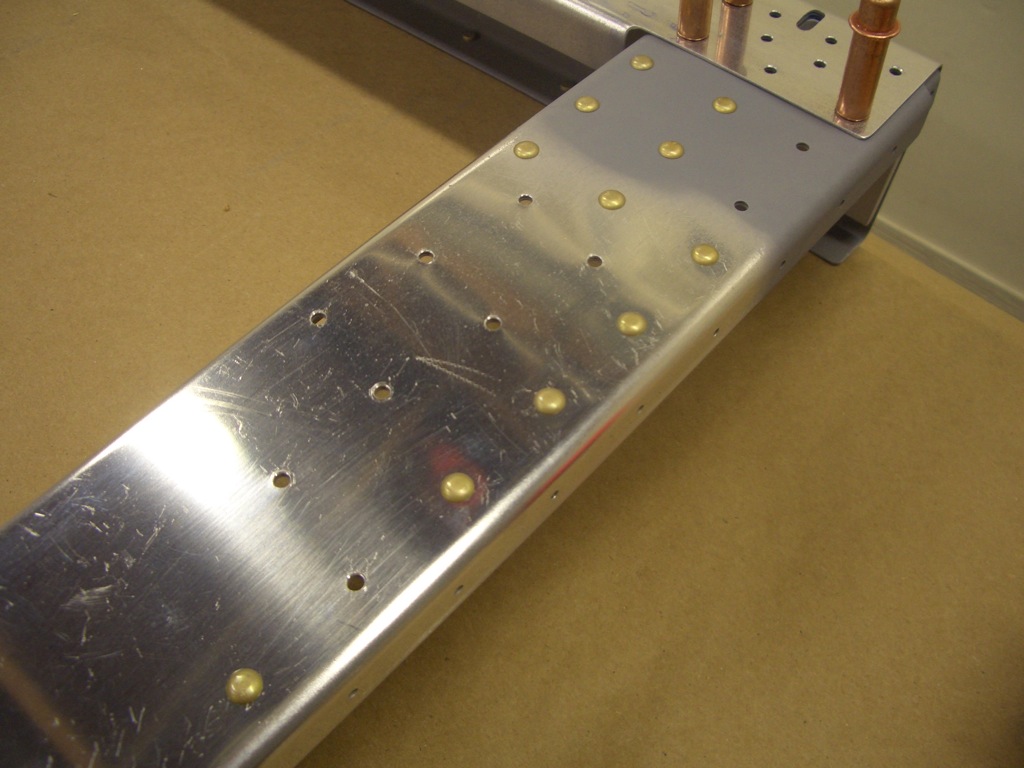
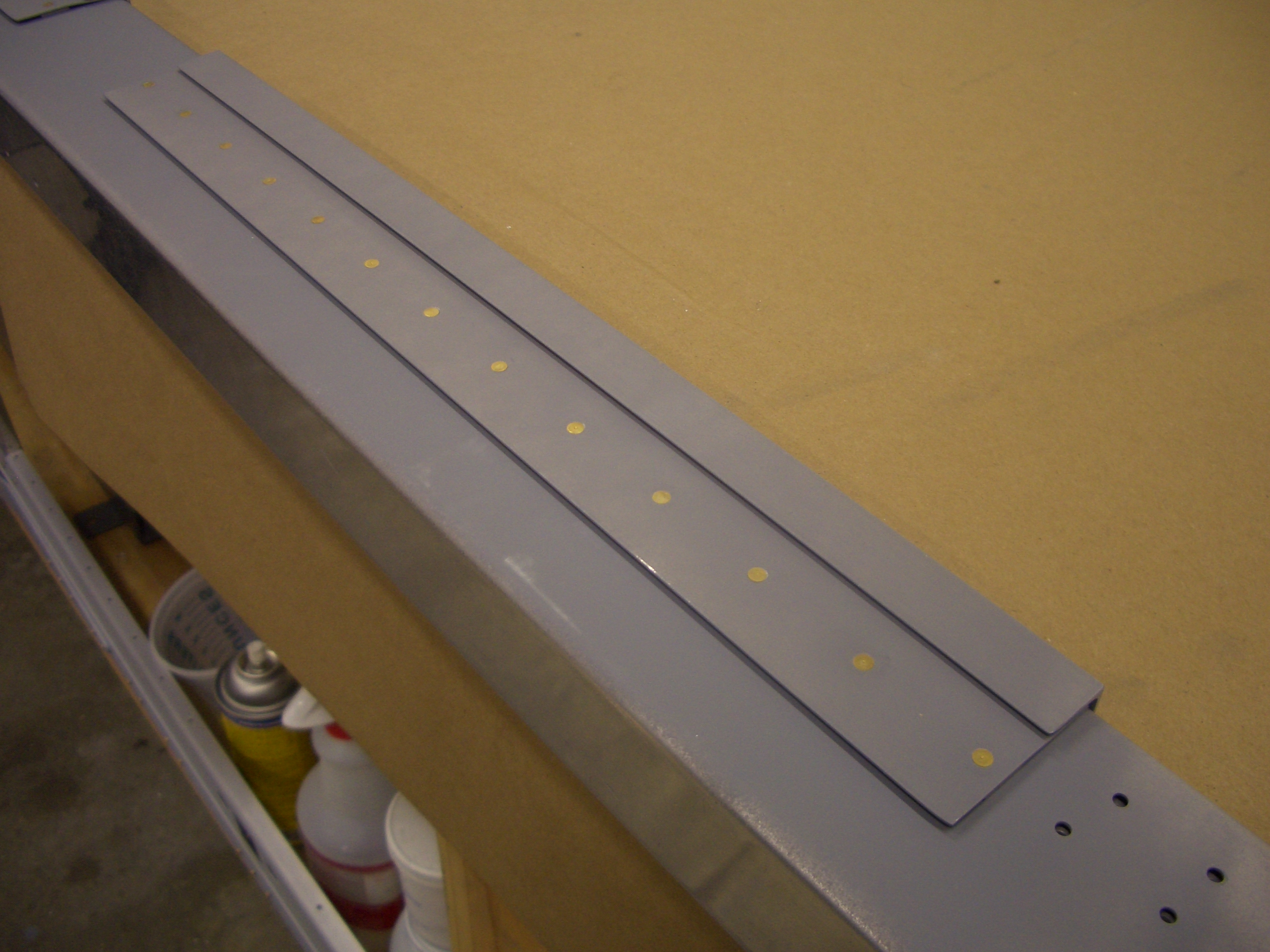
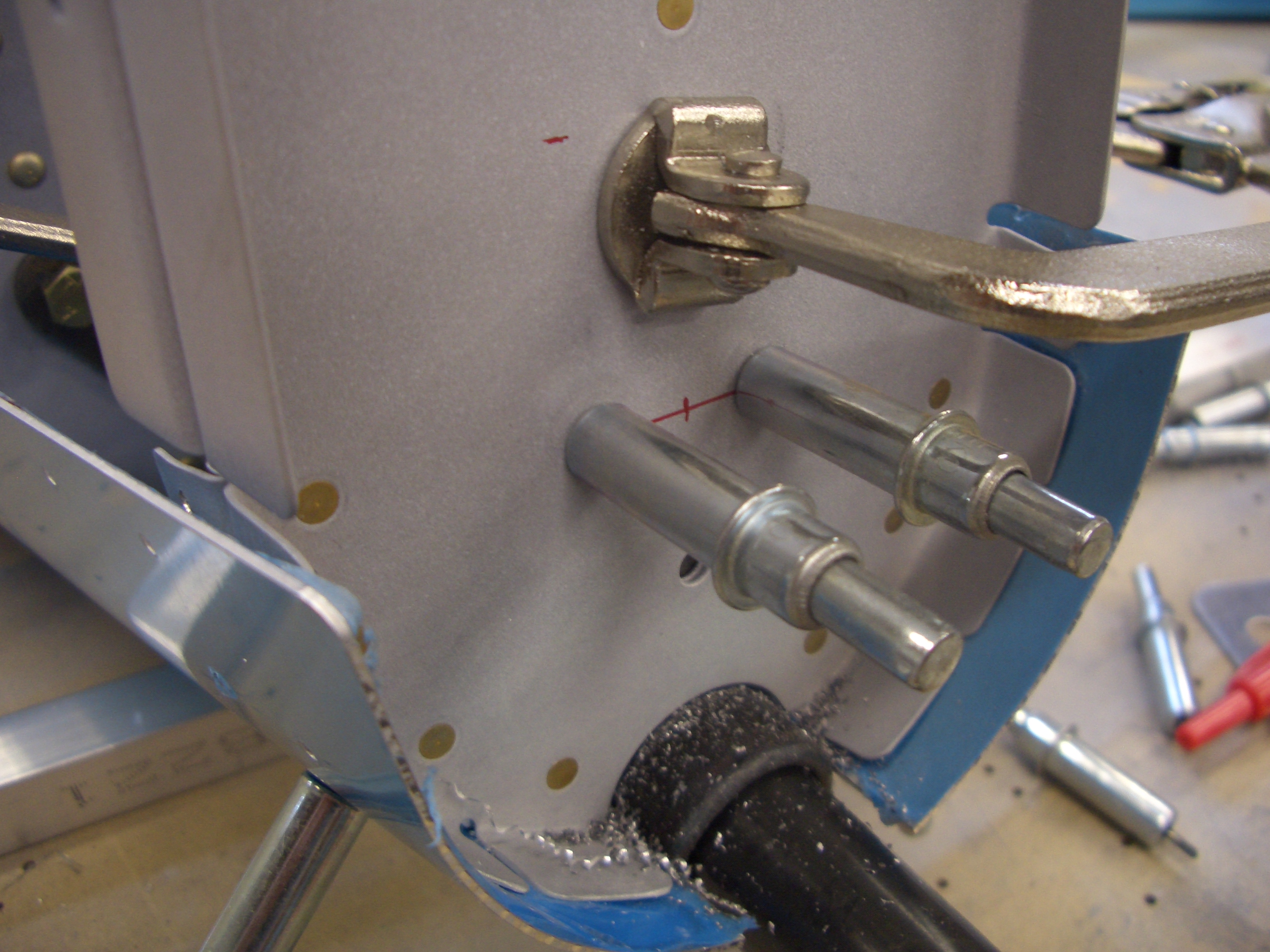
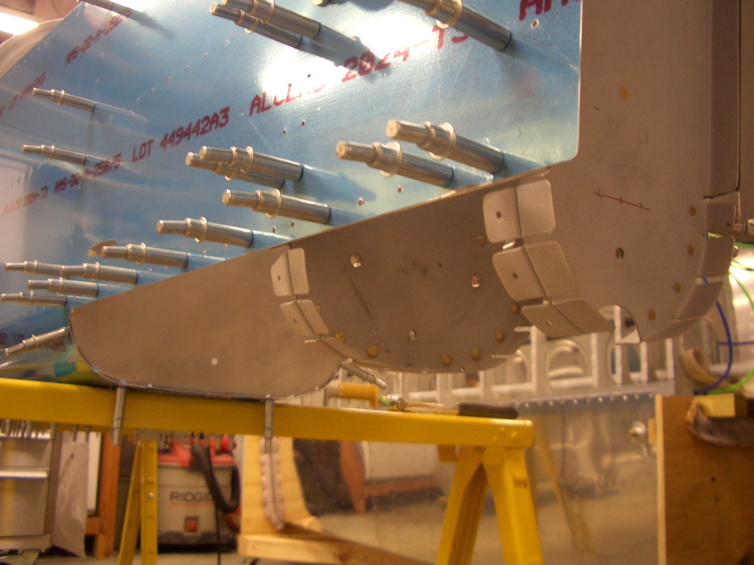
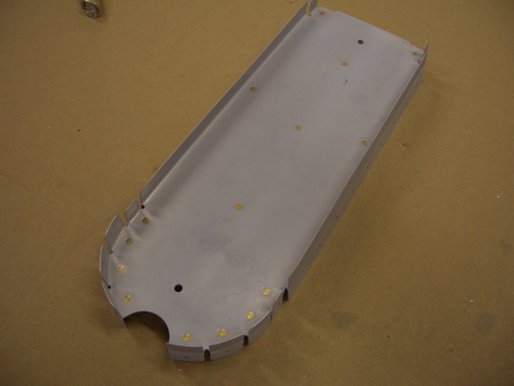
The upper seat adjustment pieces can also be riveted on now.  I used some rattle can primer on these so that I can easily remove it later when I’m ready for final paint.

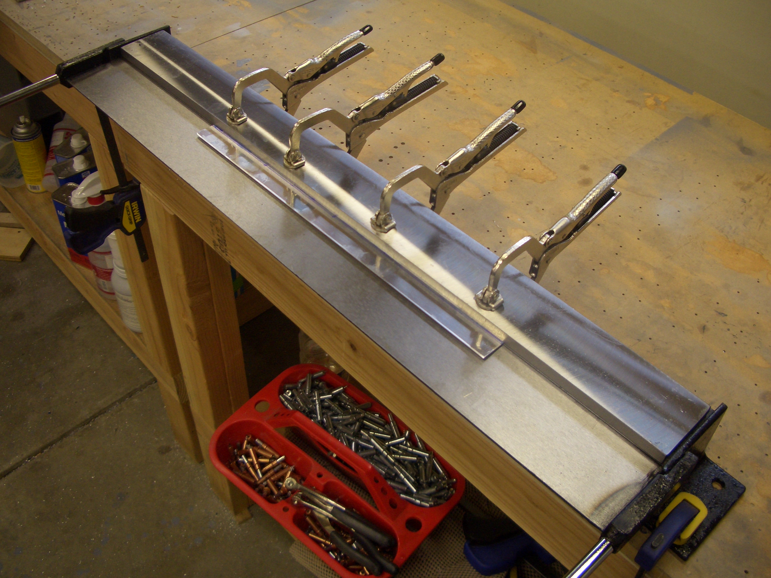
The rear bulkheads are primed with epoxy primer and just need a few rivets each to join the two halves together.

The F-706 bulkhead is riveted along the bottom, but the top is left clecoed since it is riveted in conjunction with a top skin rib.

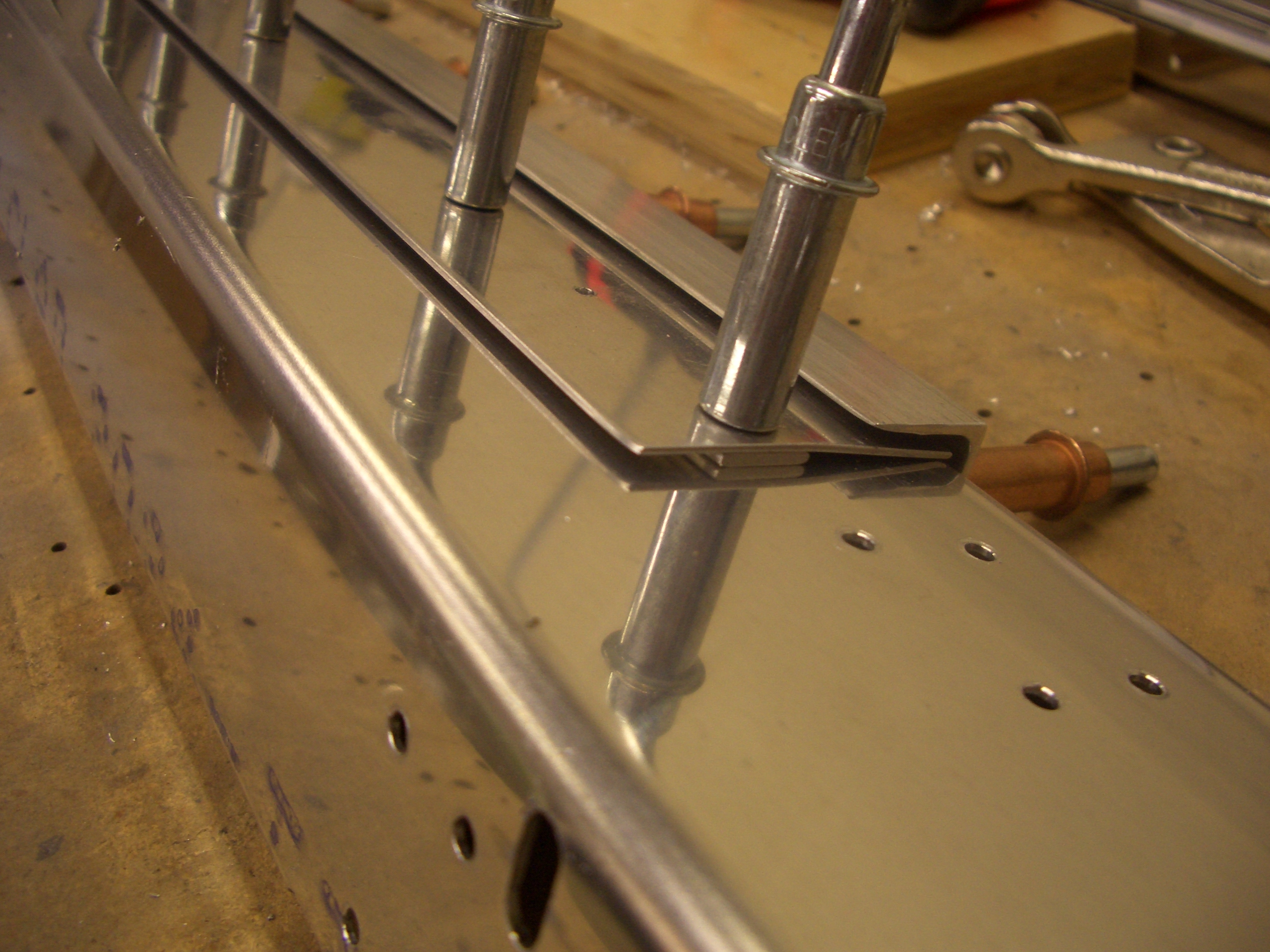
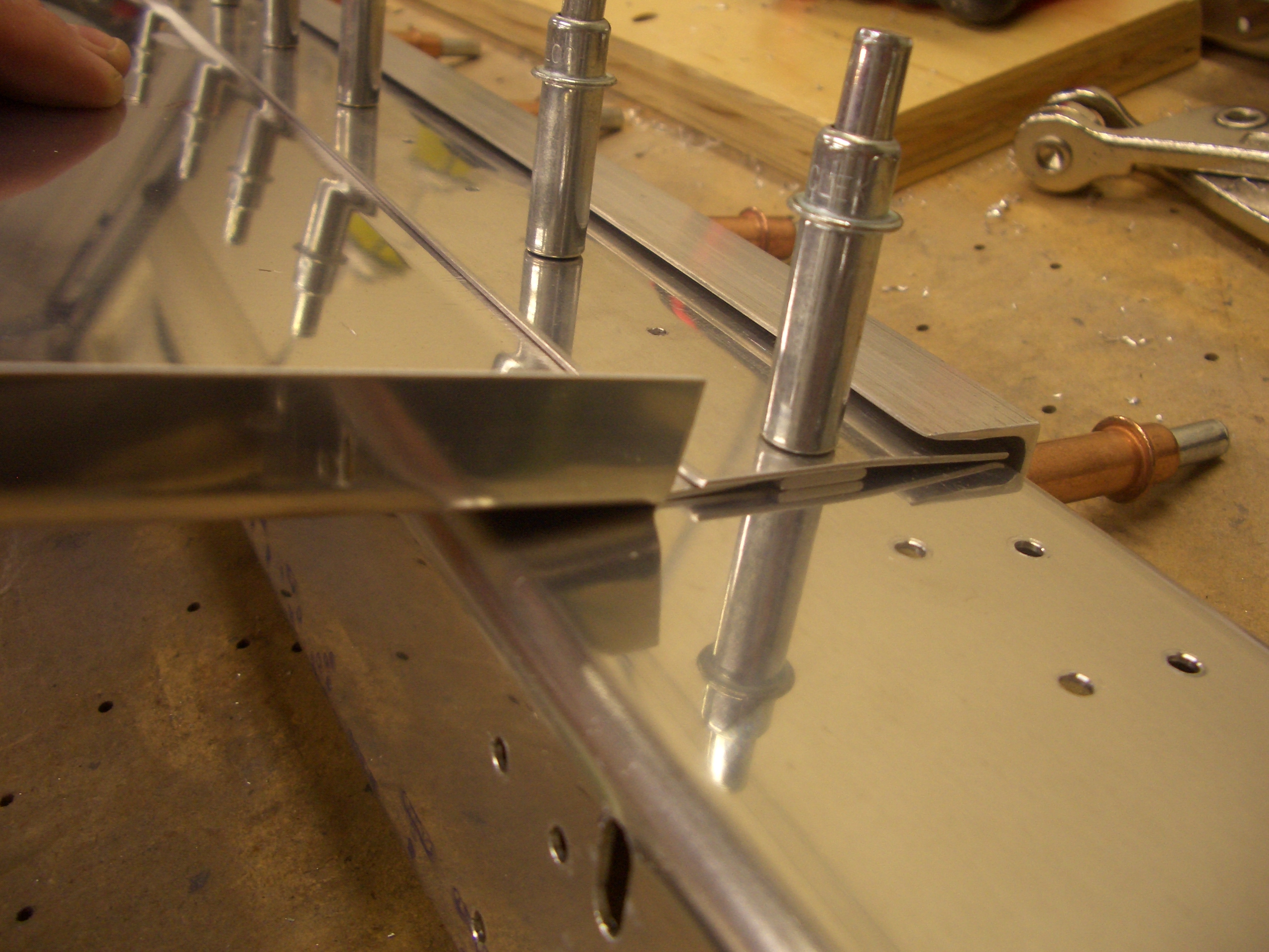
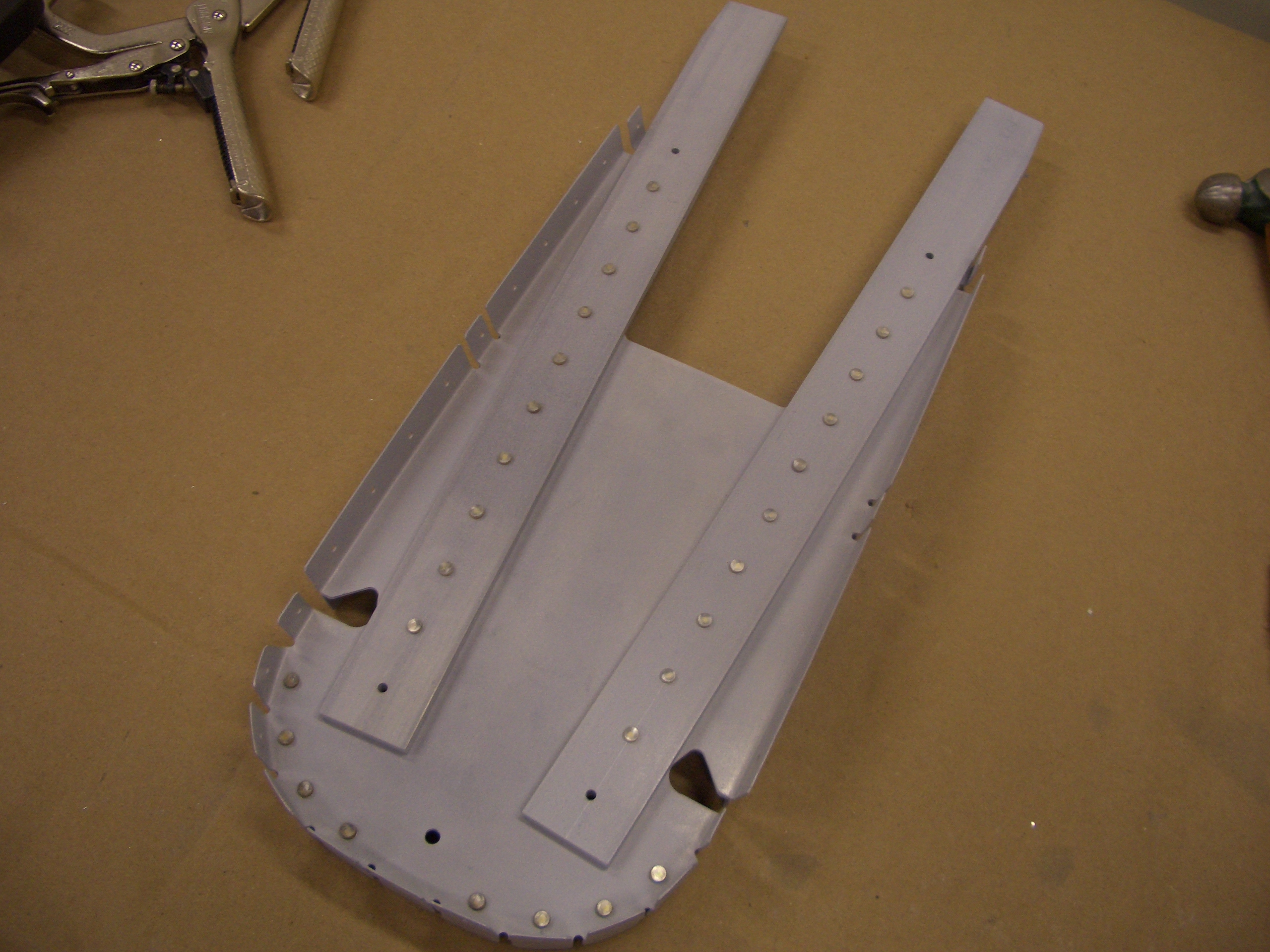
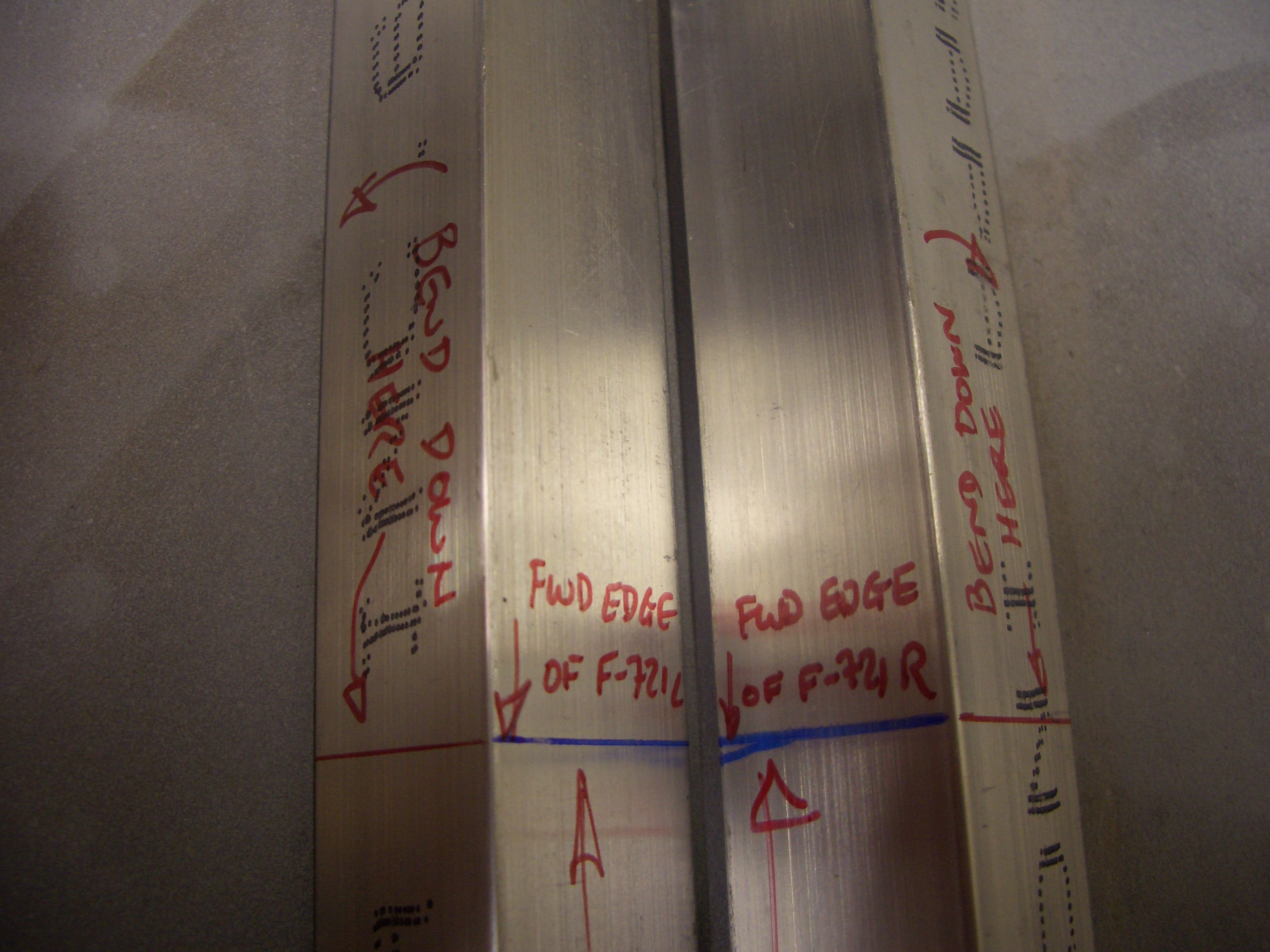
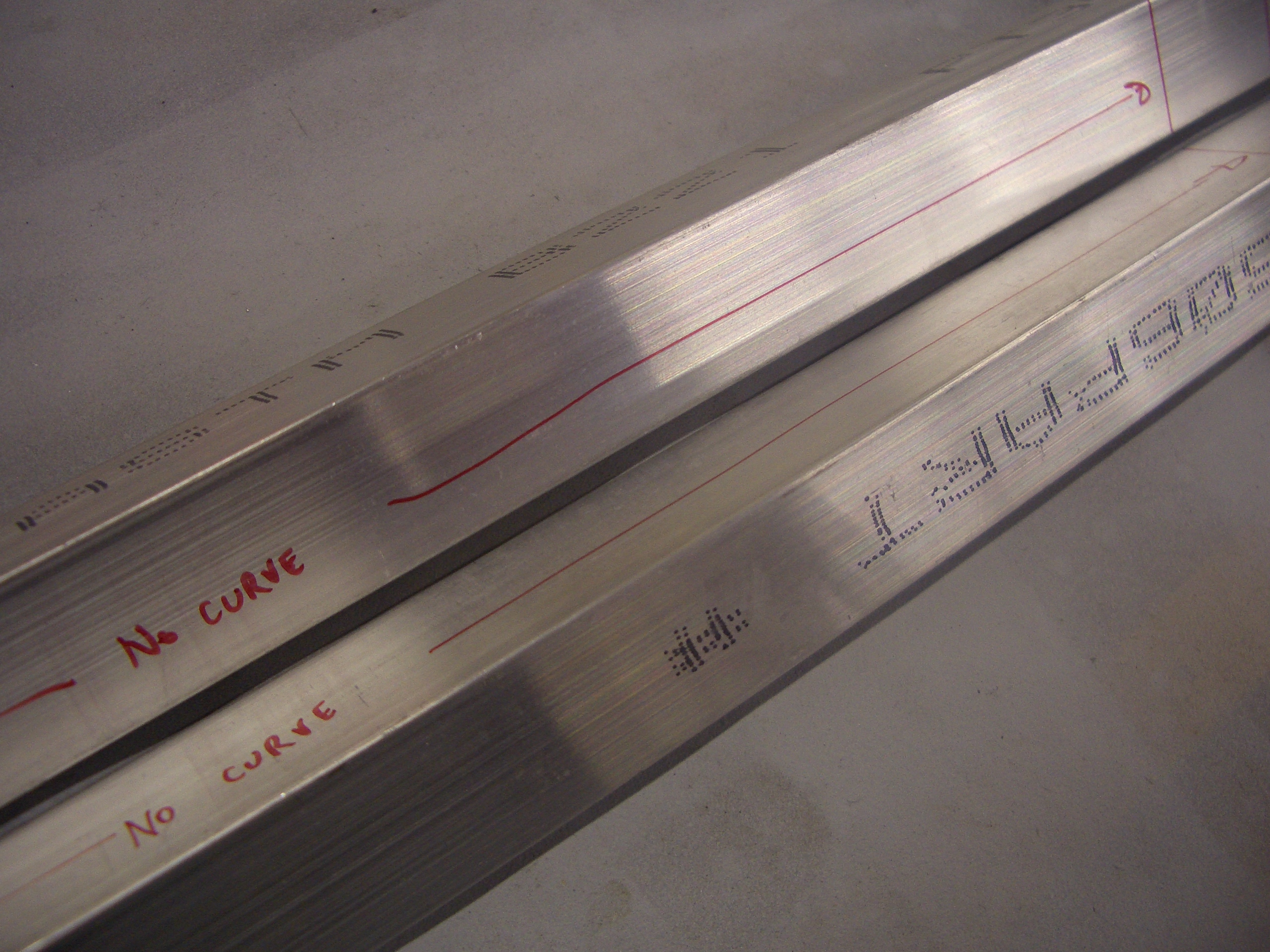
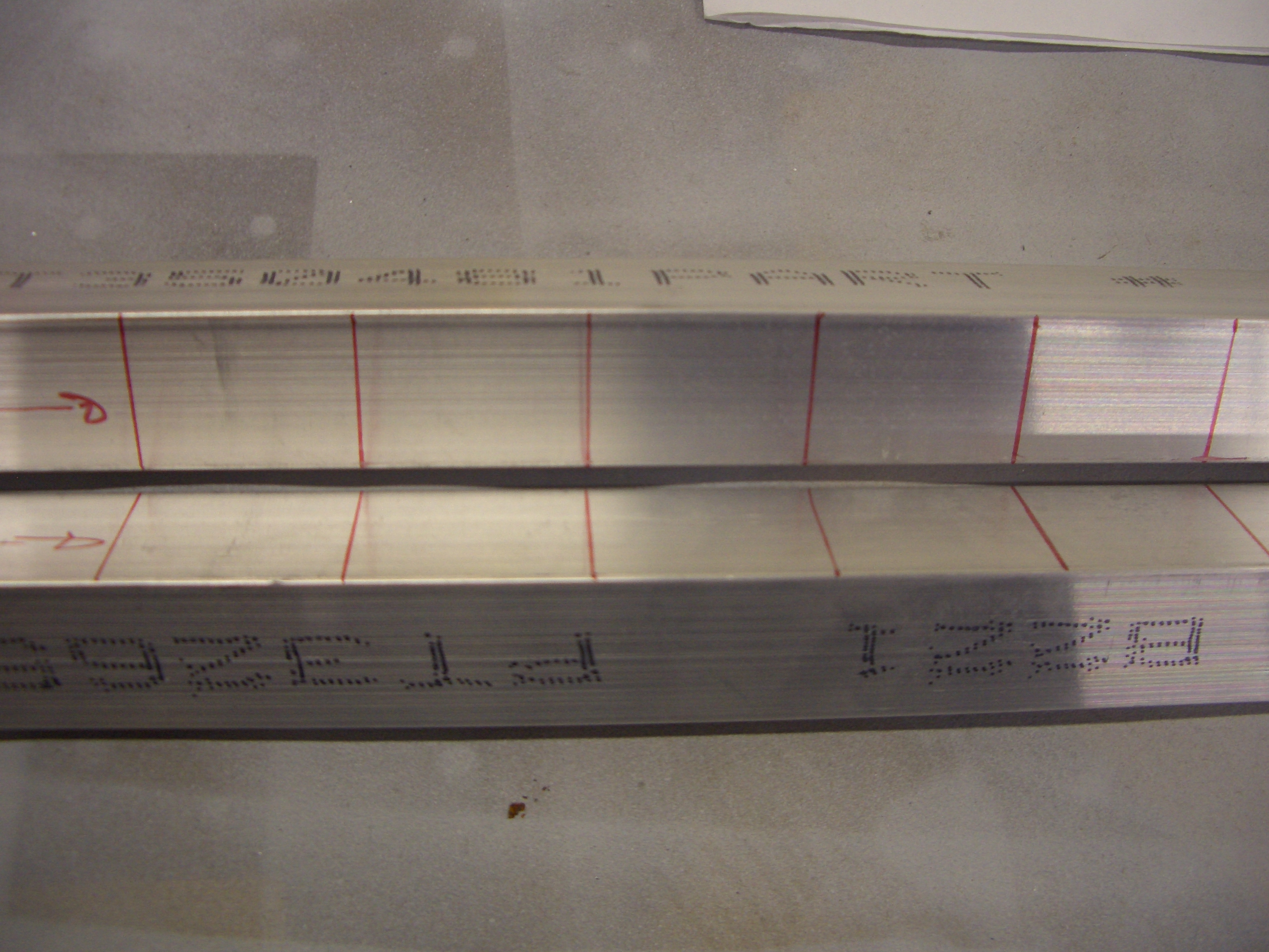
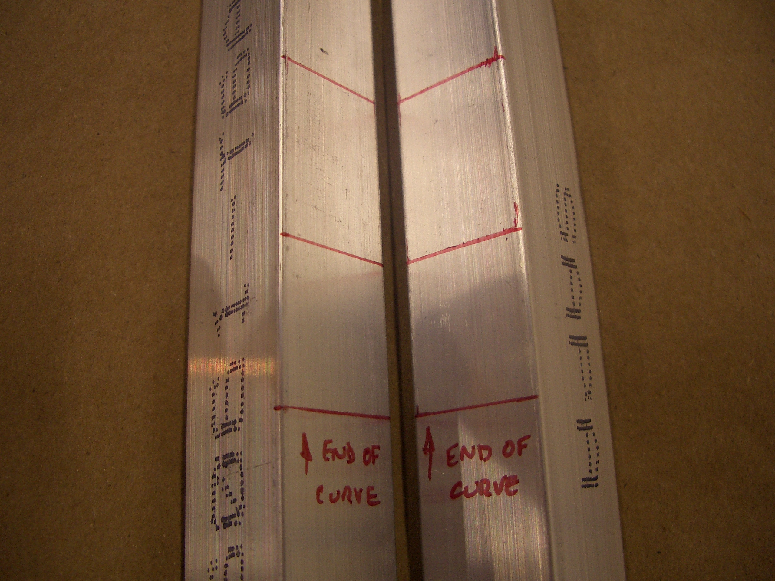
The F-711 bulkhead is riveted through the bars and around the lower curved section.  The upper and lower hole in each bar is left unriveted for now.

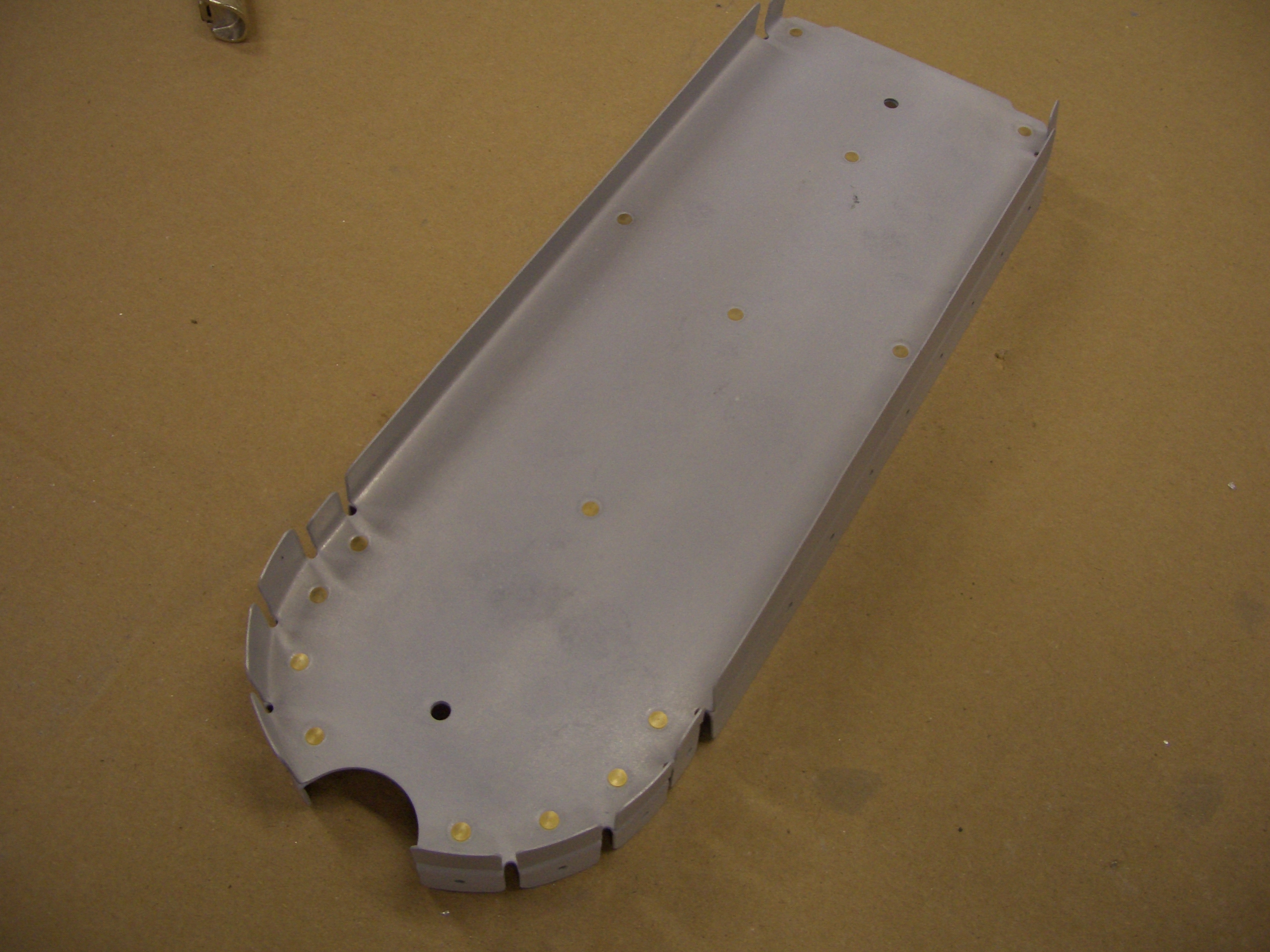
The F-712 bulkhead is riveted together using flush rivets on the aft side since the vertical stabilizer rear spar attaches here.

The F-728 and F-729 ribs that support the elevator bellcrank are attached and everything except for F-728 is riveted in place.

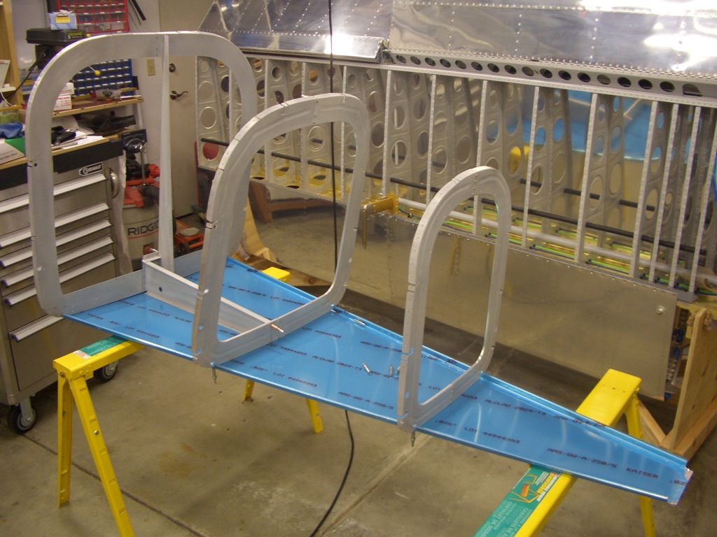
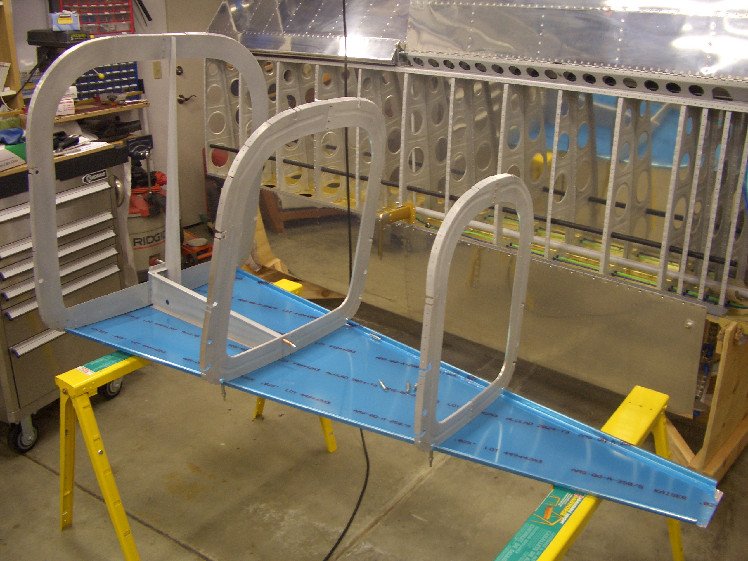
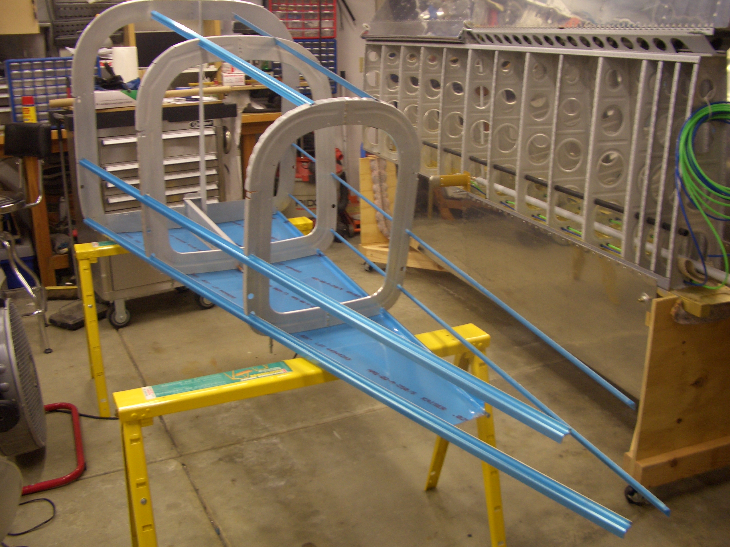
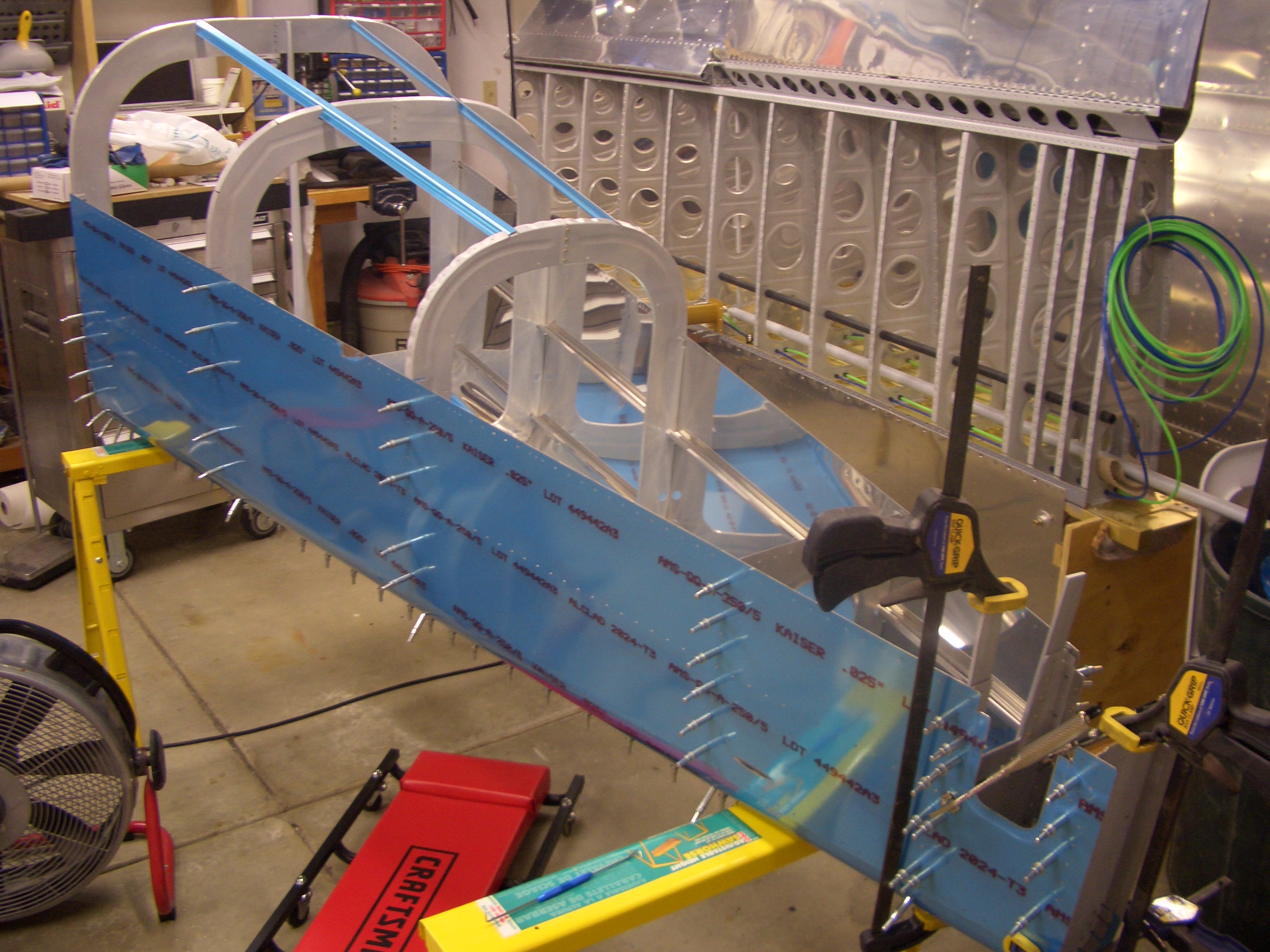
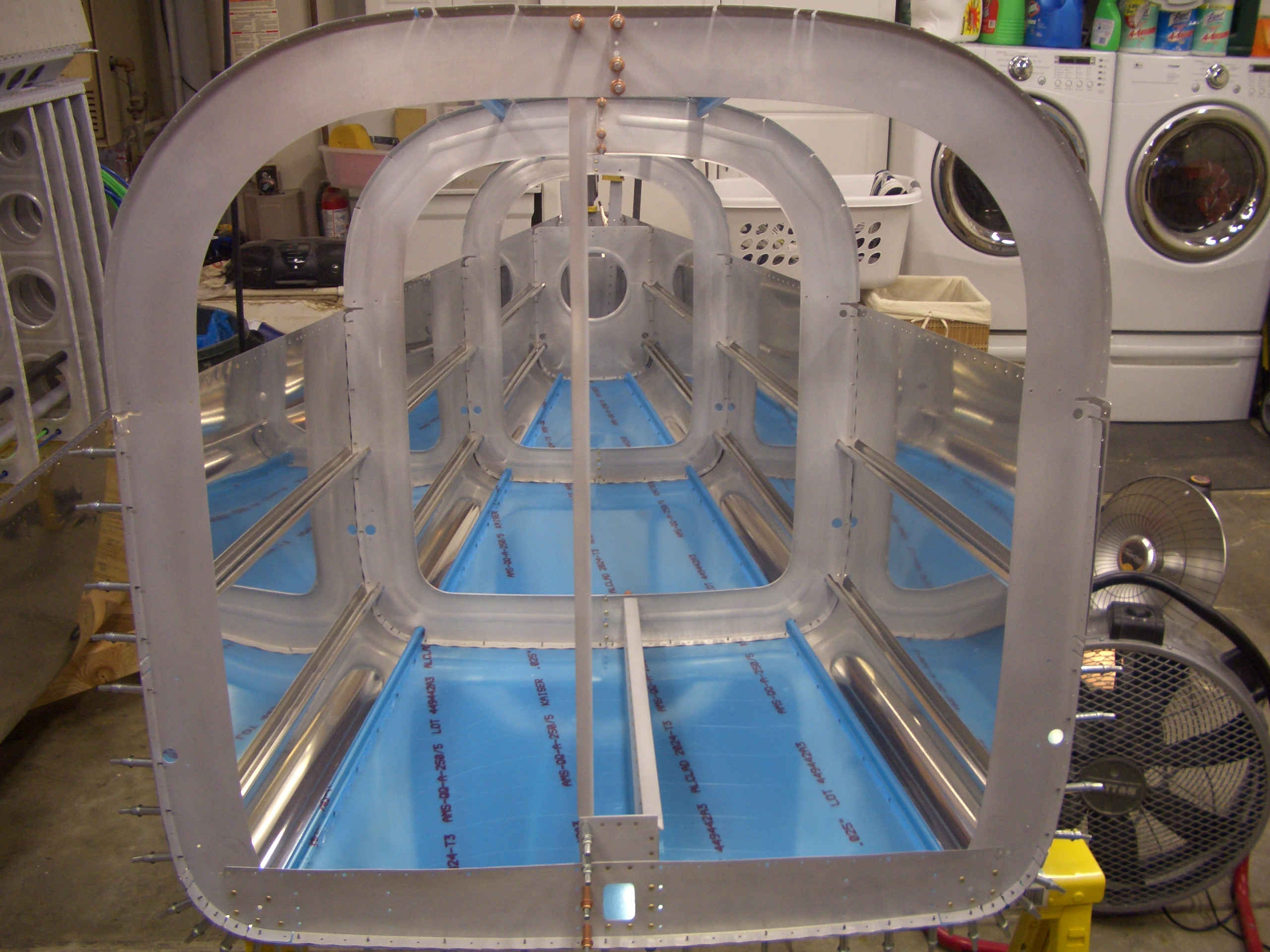
For fun, I clecoed the F-706, F-707 and F-708 bulkheads to the bottom skin to see how everything fits together.  The hole alignment is pretty poor.  The bulkheads will definitely need some fluting before everything aligns.

Started Longerons

I started working on the longerons tonight.  First up is to cut them to length.  This is a critical cut because replacing these 15′ long angles would be very expensive (both in material cost and in shipping).  These need to be cut to precisely 173 7/16″.  Since the ends of tape measures can have some slop in them, a trick to get more precise measurements is to position the tape measure at the 1″ mark.  You do have to be sure to add 1″ to your measurement to account for this though.

These suckers are long.  They barely fit across my garage widthwise because of the stuff I have lining both walls.

I used my cutoff saw to cut these about 1/8″ long and then filed them to the correct length.

The aft ends of the longerons need some material removed.  I misread the plans at first that called for a 1/8″ radius and drilled a 1/8″ hole (1/16″ radius).  I fortunately had drilled the hole far enough away from the lines that I could file the radius to be 1/8″ and still not cross the lines (though it doesn’t look like it from this picture because of the burr around the hole).

Here are both ends cut and polished.

Next up is to lay out for the bends.  These lines define the forward end of the F-721 side rails and the point at which the longerons bend downward to meet up with the firewall.

The longerons are straight for the next 10+ inches or so, then curve inward to define the shape of the fuselage.

I placed marks every inch or so to help with the alignment during bending.

This is the rear end of the curve.  The longerons are straight from this point back to the tail.  It’s nearly midnight, so I’ll get started on the bending tomorrow.

Started Bending Longerons

I started bending the longerons tonight.  The instructions specify that they be clamped in a vise, bent a little to put some preload, then hit with a rubber mallet to bend it slightly.  Move the longeron down an inch or so and repeat.  The problem is that any bend you add in one axis creates an inadvertent bend in the other axis as well as a twist.  You then need to clamp the other leg of the angle in the vise and remove the inadvertent bend and use a crescent wrench to remove the twist.  Unfortunately, that removes some of the intentional bend.  It’s a very iterative process.  Van’s specifies that the bend needs to be accurate to within 1/16″, but I’m shooting for no more than 1/32″.

I’ve heard several builders recommend that you spread the bending over a number of small sessions instead of trying to do it all at once since it can be quite frustrating.  I spent about 30 minutes tonight getting an initial bend into each of the longerons.  This is within an inch or so of the template, so there is a lot more tweaking to do, but it’s a start.

Worked on Left Longeron

I started tonight by making a template (shown in the middle here).  I glued the bending template from the RV-7A page to a piece of 1/4″ MDF; cut it out and sanded to the line.  I then spent about an hour fine tuning the bend on the left longeron.

Here is the template sitting on the left longeron.  As you can see, the far end (rear end) still needs a little fine tuning, but the rest of the bend is within 1/32″ or so and the longeron is pretty close to flat and zero twist.  A lot of builders complain that bending the longerons are really frustrating (and Van’s instructions describe it as maddening), but I haven’t found the process too bad at all.  If you take your time and make gradual bends, it’s pretty straightforward.

Worked on Tailcone

The tailcone has six stringers that must be cut to length.  The ends also need some shaping, but fitting them to the tailcone now will allow me to shape the ends to fit the bulkheads precisely.

Next up, I fit the tailwheel spring mount between the last two bulkheads.  This will eventually be bolted to both of them.  These are both double bulkheads, and they’re riveted to both the side and bottom skins, the side stringers and the longerons.  Needless to say, this will be a phenomenally strong part of the airplane.

This skin needs an arched section removed to allow the tailwheel spring mount to stick through.  The plans provide a template for the shape of this.  I traced it onto a sheet of paper and transferred it to the tail skin.  It was pretty close, but required a little further sanding right at the rear edge of the mount.

I then clecoed the tail skin to the bottom skin and slid the stringers into place.  I’ll trim the stringers tomorrow and then the side skins can be clecoed on.

Assembled Tailcone

I went out this morning before work and drilled the tailwheel spring mount to the F-711.  It took quite a while to ensure that the mount was centered, square, and the tailwheel was exactly vertical.

F-712 gets a couple of keeper rivets to hold the mount in place until the bolt holes can be drilled in conjunction with the vertical stabilizer rear spar.

Unfortunately, one of the holes came out slightly under the recommended edge distance of 1.5D (12/32″ in this case).  I need to run this by Van’s and see if they think this is an issue.

Update: Ken Scott at Van’s said not to worry about 1/32″, especially in steel.  “Build on” as they say…

I clecoed the tailcone together.  Getting the stringers in gets a little tough once all of the bulkheads are in place, but I eventually got it.  The ends of the lower four stringers need notches cut in each end to clear the bulkheads.

Here’s a shot looking down the tailcone from the other end.  The vertical rib connecting the top an bottom of the closest bulkhead as well as the horizontal rib that connect the closest two bulkheads are supposed to be off center.

The holes in the tail skin don’t even come close to lining up with the holes in the side skin.  I need to do a little research on this to see how to get these to align.  I can’t just pry them into alignment since there is a stringer right on the other side of these holes that would prevent inserting a cleco through the hole after aligning.

Fit Tail Skin

Like I mentioned yesterday, the holes in the tail skin didn’t come close to aligning to the side skins.  I couldn’t pry the skins into alignment and hold them with clecos because there is a stringer right behind the row of rivets along the bottom of the side skin and the stringers don’t have any holes in them.  The fix turned out to be relatively simple.  Remove the side skin, match drill the lower stringers through the holes that will be shared with the tail skin, then cleco the tail skin back on.

Getting the tail skin out without removing all of the bulkheads required removing a fair number of clecos at this end of the fuselage.  Here, I’ve match drilled the lower stringers from F-710 back.

Now the F-779 tail skin can be fit.  Putting in the clecos on the first side was pretty easy, but the second side was pretty tricky.  The fit is really tight in this area, so it takes a fair amount of force to get the holes to align.  I worked my way from the front to the back one hole at a time and eventually got everything aligned nicely.

It’s hard to see here, but I hung a plumb bob through the top tooling hole of F-712 and shimmed the tail until the string bisected the bottom tooling hole.

I then hung a second plumb bob from the upper tooling hole in F-706 and shimmed the front until this was centered in the opening.  It’s too late to start drilling tonight, so I’ll start this tomorrow.

Drilled Tailcone Stringers

Jenn helped me raise the tail so that the plumb bobs would be more accurate and then I reshimmed the tailcone so that there was no twist.  I then drilled every fourth hole down the stringers (the horizontal rows of clecos in this picture).  The tailcone is pretty stiff now though it can still be flexed a little bit until the aft top deck is riveted on.