Installed Right Cap Strip

I riveted the right cap strip in place.  Doing this many pop rivets in a row with a hand pop-riveter is a killer on the hands and forearms.  I really wish I had purchased a pneumatic pop-riveter near the beginning of the project.  There are probably not enough remaining pop rivets left on the plane to justify purchasing one now though.

Here’s a closeup of the forward armrest support.

And here’s the aft armrest support for the right side.  I installed this with solid rivets since I had access to the back side.

Finished Drilling Armrest Reinforcement Angles

I finished drilling and deburring the reinforcement angles to the armrests.  Rivets will be spaced on roughly 1″ intervals on the top and side of the angles.

Here’s the angle that will tuck up under the armrest.  I just need to countersink these holes and dimple the armrests and these will be ready to rivet.

Finished Armrest Reinforcement Angles

I countersunk the reinforcement angles and dimpled the armrests.  After edge finishing the armrests, I primed and riveted the parts together.

Here’s a closeup of how tightly the angle fits against the radius of the armrest flange.  I was a little worried that the 0.063″ angle wouldn’t be stiff enough since there was quite a bit of flex when these were just clecoed on.  After riveting these, these are very stiff.  I’m really glad I didn’t go with the 0.125″ angle since that would have added a fair amount of weight.

Replaced Flap Position Sensor Wiring and Worked on Air Vent Bracket

Since I had some extra trim servo cable, I replaced the three wires from the VP-X to the flap position sensor.  I’m trying to keep all wires color coded where possible and these were three wires that didn’t match up with the colors on the sensor.

Now the only wires that need to go up into the flap housing are the two flap motor power wires and the trim cable.

I also worked a bit on the air vent brackets.  I ended up just cutting these off straight across instead of stepping down.  I had Classic Aero Designs ship me the side panels so that I can cut them to fit snugly around these brackets since they’ll be shorter than stock.

Replaced Andair Fuel Pump

Andair recently posted that they had updated their fuel pump design and offered a free upgrade for anyone that had purchased one of the older designs.  Mine arrived today and I quickly installed it.  The controller is now integrated, so that leaves an empty spot next to the pump on the mounting bracket.  I don’t think I’ll mount anything here though.

Worked on Instrument Panel and Air Vents

I fabricated the additional clips that attach the instrument panel to the forward canopy supports.

Here’s another shot from behind the instrument panel showing where these clips attach.  You can also see that I’ve finished the left air vent support bracket and drilled it to the side skin.

Here’s the front side.

I only used the top three holes to attach the bracket since these vents are smaller than the Van’s stock plastic vents.  I’ll fill the bottom holes with an extra rivet.

Here you can see how I ensured the air vent brackets were coplanar before drilling the brackets to the side skins.

Finished Sealing Cowl and Riveted ELT Shelf

I got up early this morning and finished sealing the inside of the lower cowl.  It doesn’t look like applying tinted epoxy is going to work very well.  The coats of epoxy are so thin that they’re translucent.  It would take so many coats to make an opaque white layer that it would be pretty heavy.  I’m going to end up just painting this white like most builders do.  The epoxy and filler still did a great job sealing the surface to keep oil from soaking into the fiberglass though.

My buddy Andre stopped by mid-morning and helped me finish riveting in the ELT shelf.  Afterward, I reinstalled the ELT.  We also riveted in the transponder antenna doubler that I fabricated and then I installed the antenna cable.

Installed Control Sticks and Started Aileron Trim

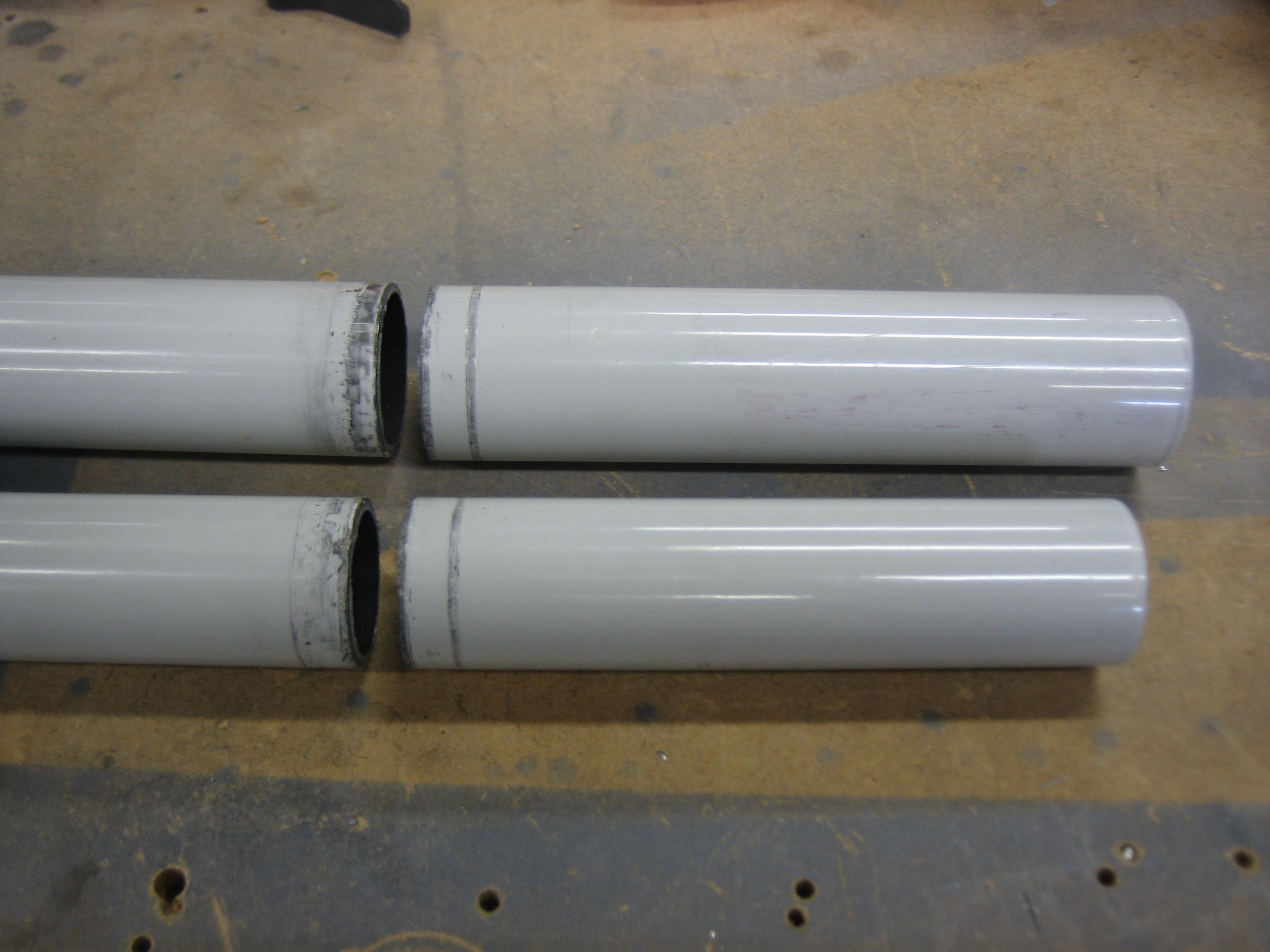
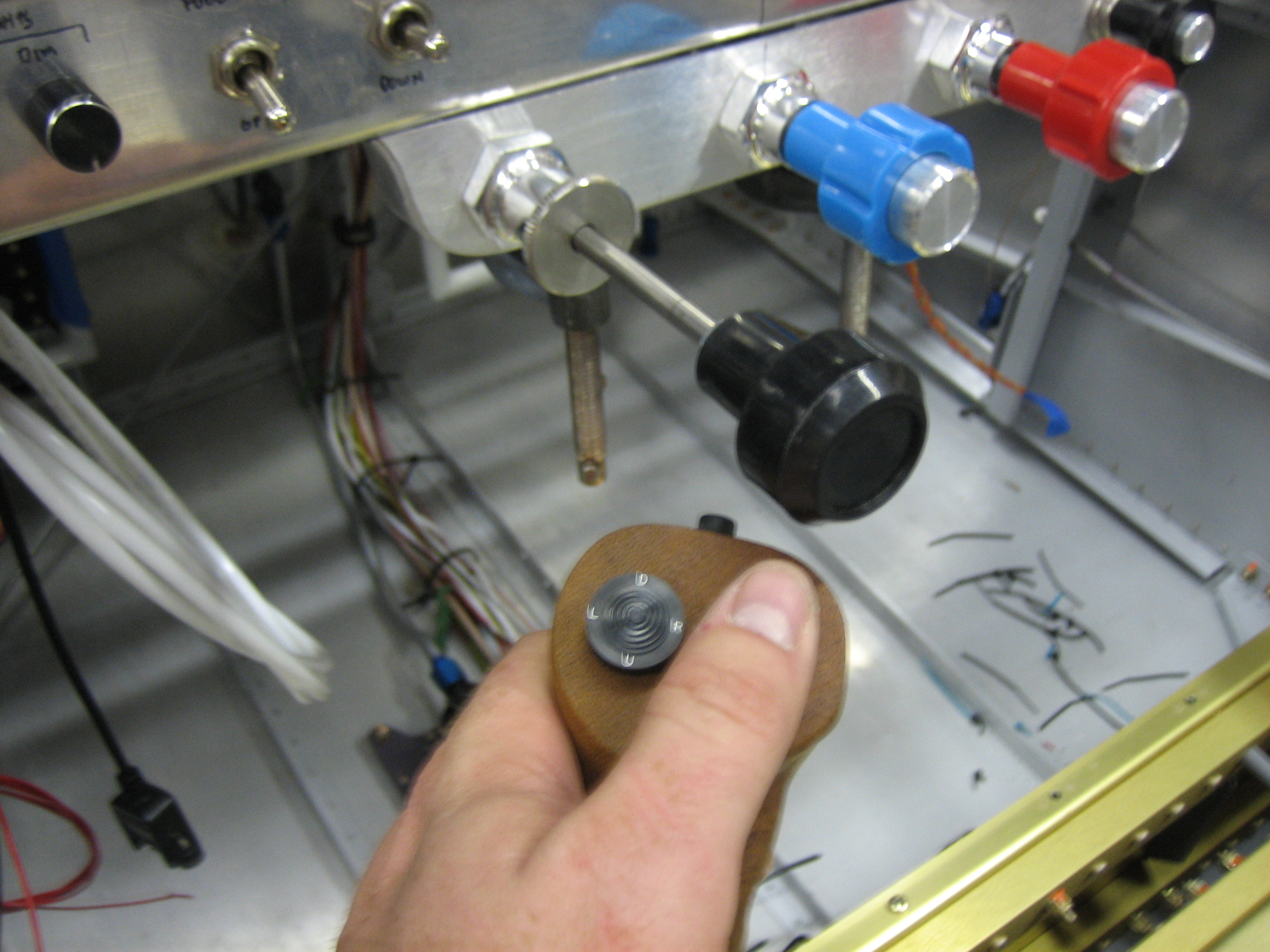
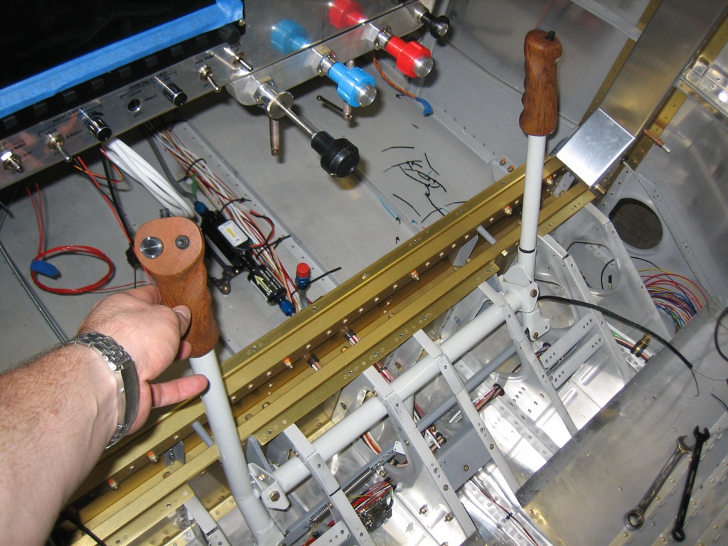
With the engine controls in their final location, I marked both sticks and cut them off.  I’m using the teak grips, so they extend the sticks a couple of inches or so.  For reference, I cut 4 1/4″ off the pilot’s stick and 3 11/16″ off of the co-pilot’s stick.  This puts the bottom of the grips (and therefore the hand) the same distance from the pivot point for either stick.

I needed to cut this much off to ensure the grip clears the throttle when at idle.  This gives me a comfortable clearance even with my finger on top of the grip.  It might be a little tight if my hand is resting on the throttle at the same time, but I don’t want to cut off any more than I need to.

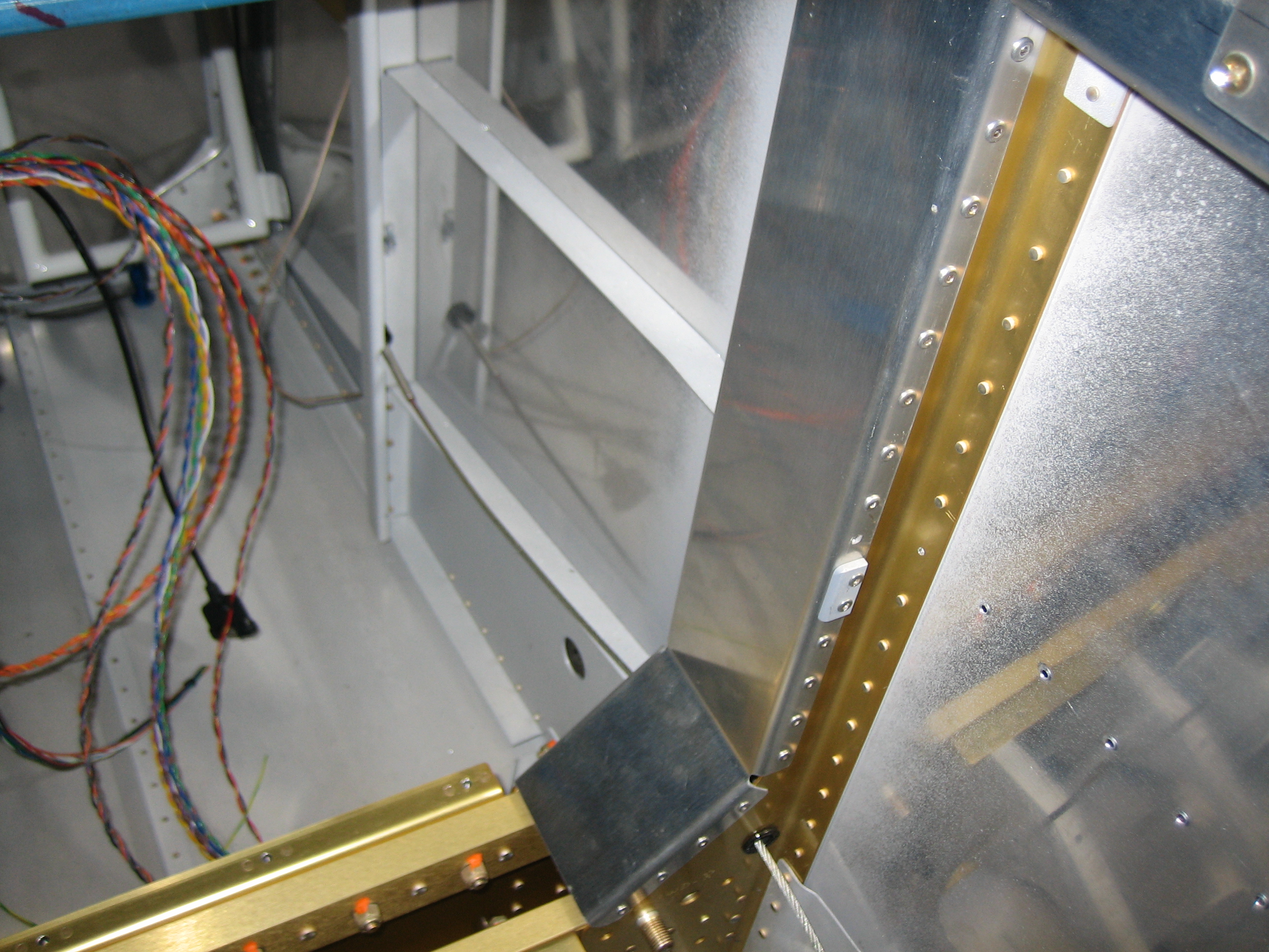
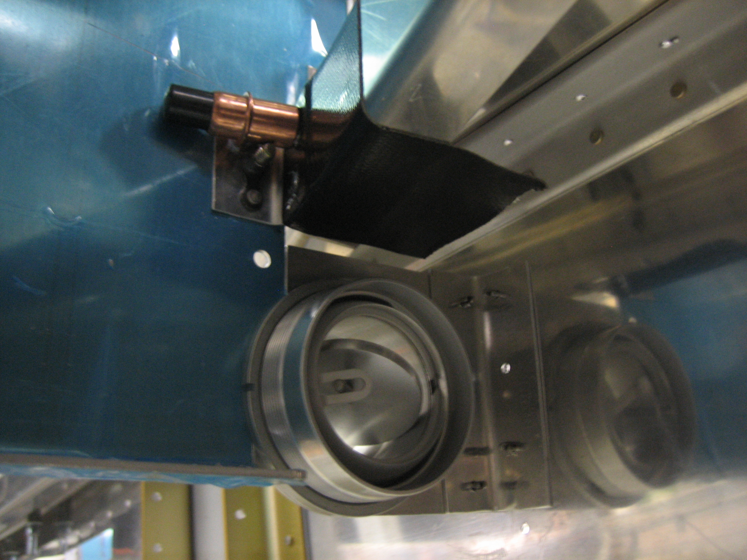
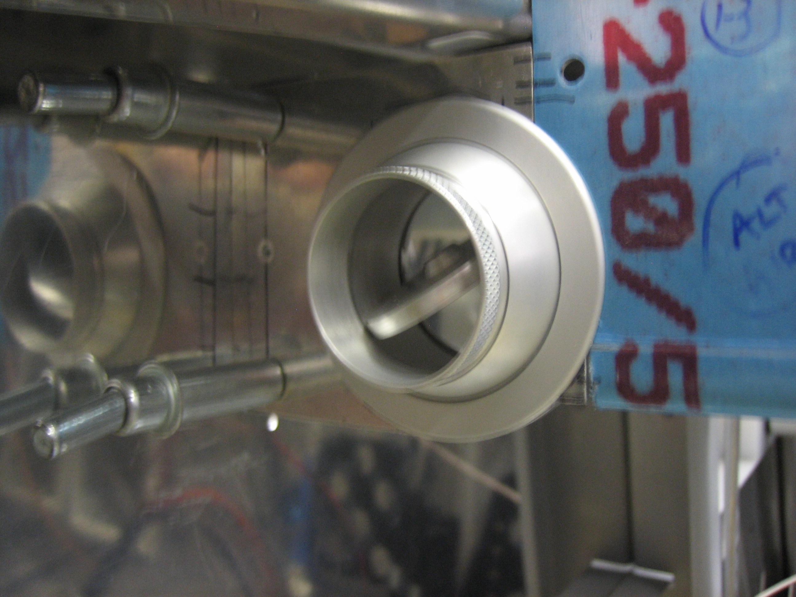
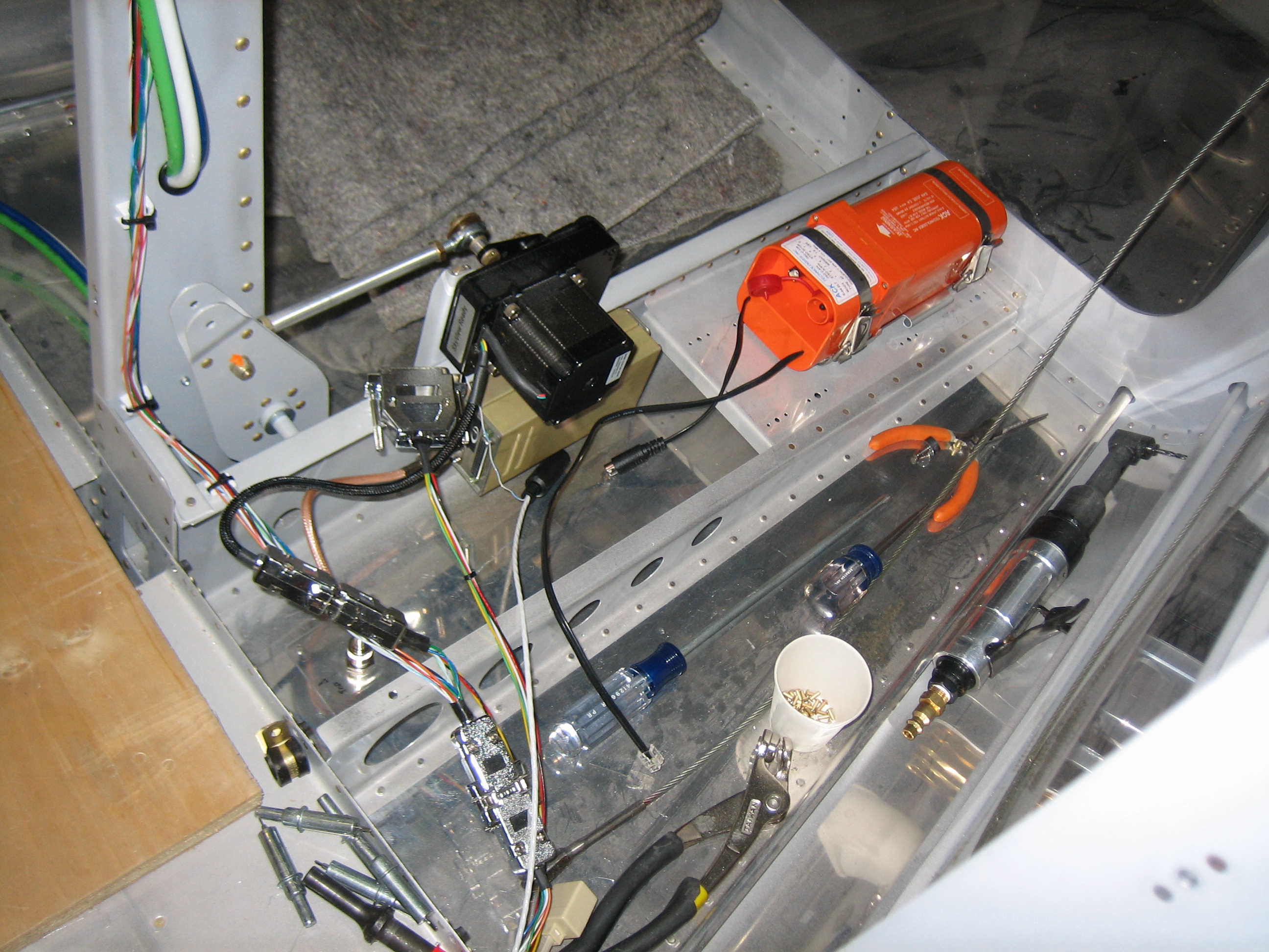
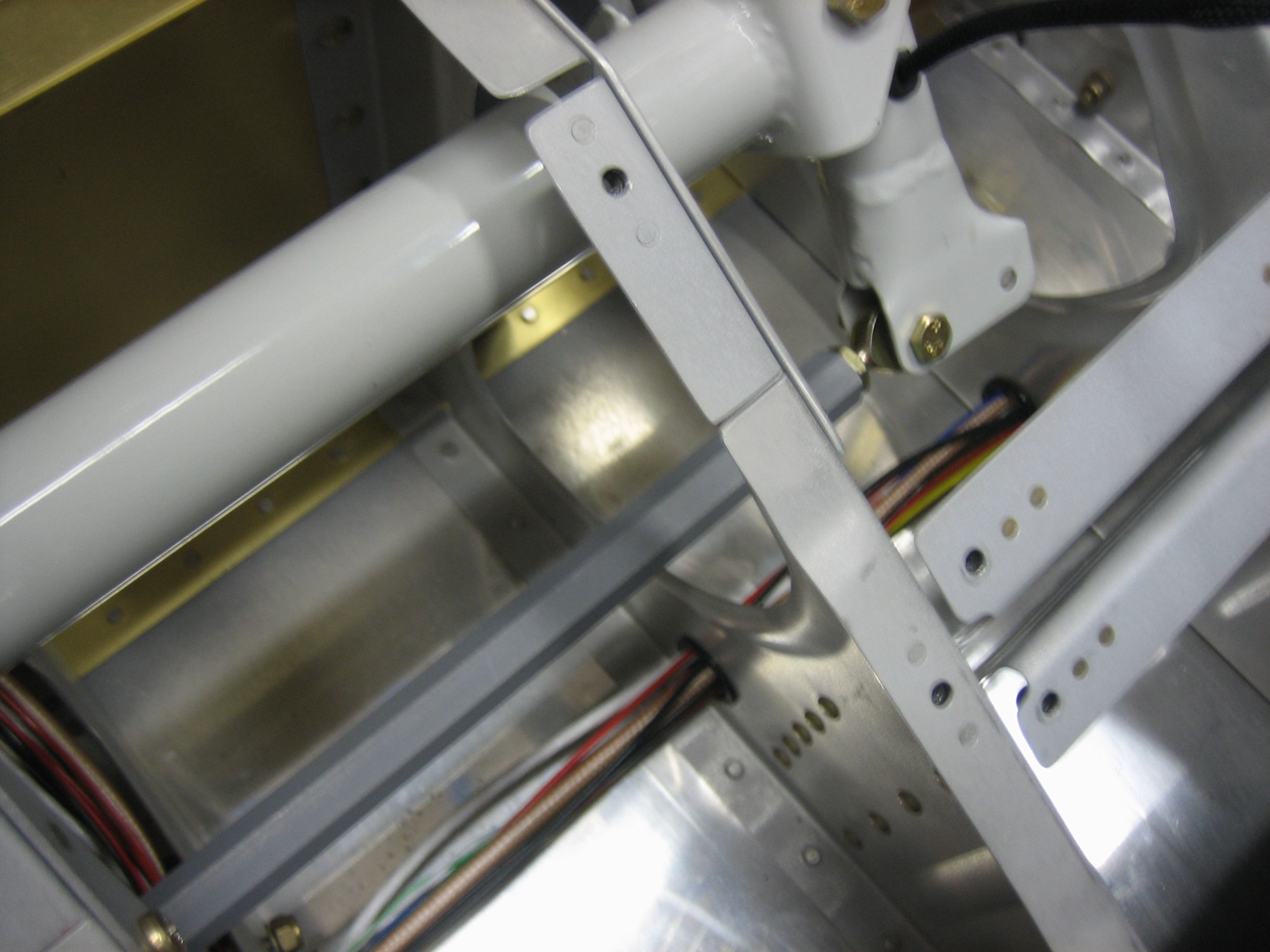
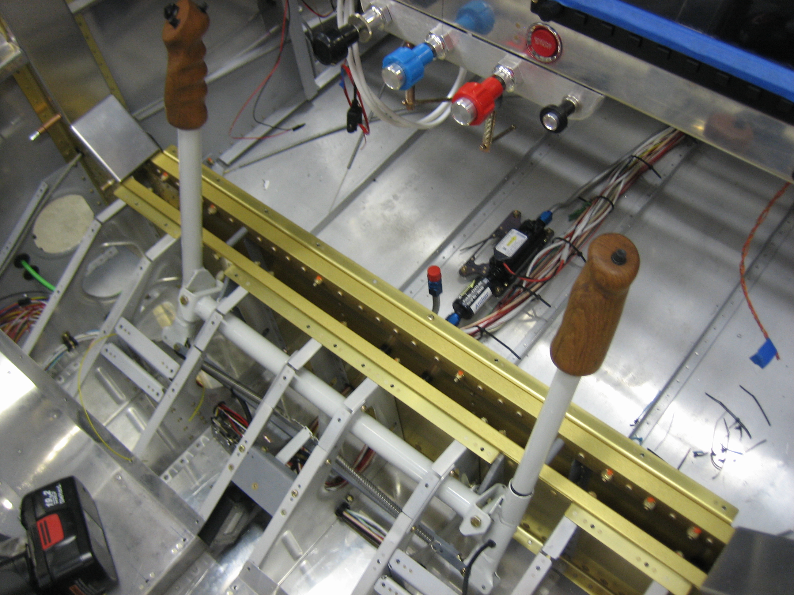
I installed both sticks and the push-rod that connects them.

The pushrod transfers the aileron control between the sticks and between the wings.  I did forget to install the aileron trim clips the first time I installed the pushrod.

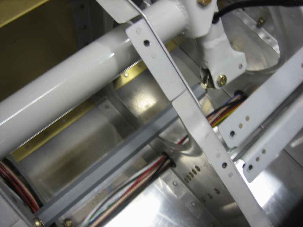
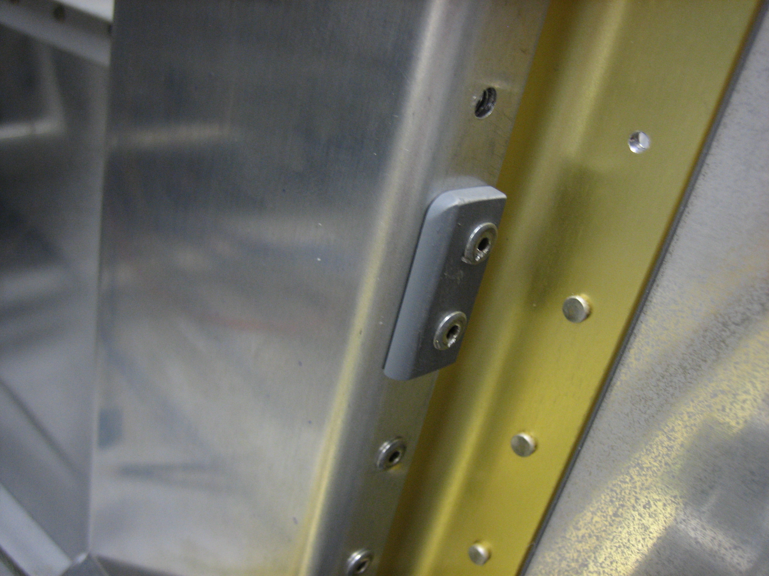
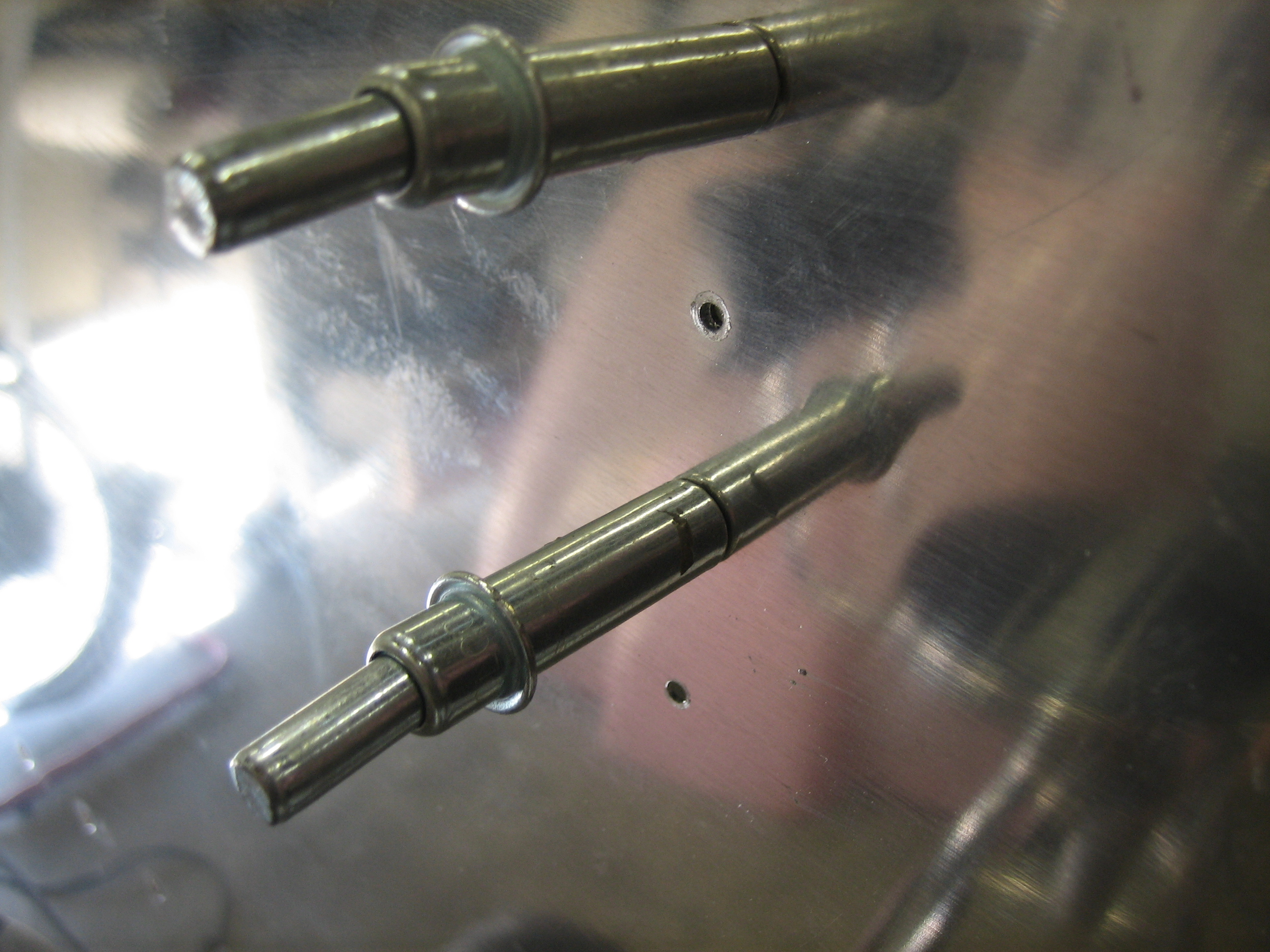
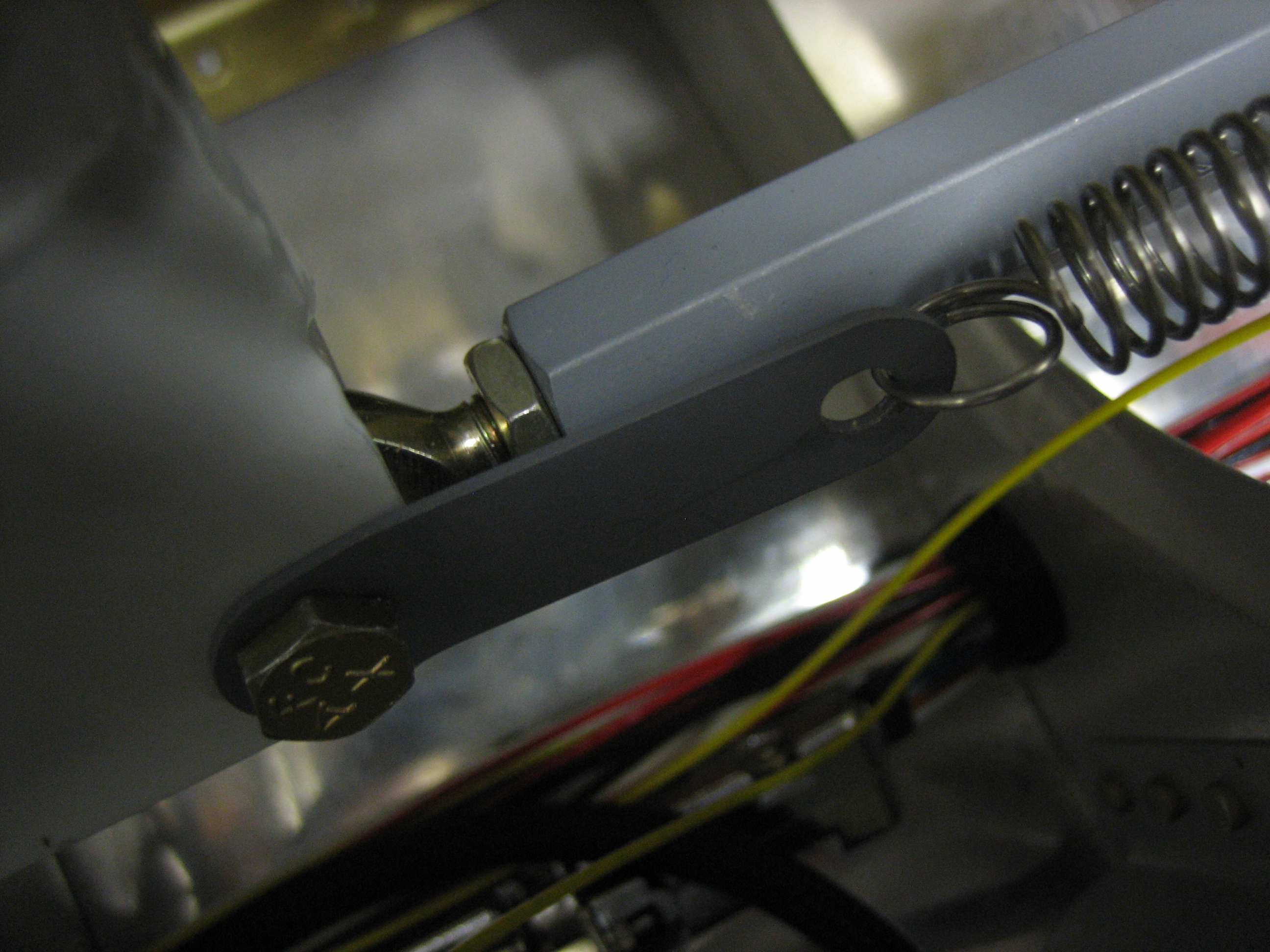
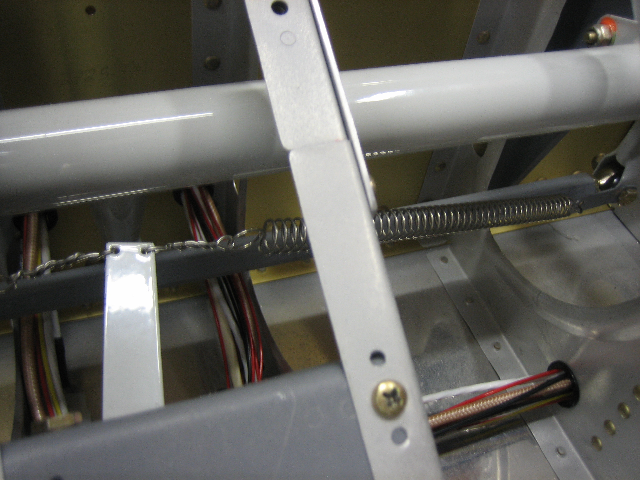
Here’s where the clip should be installed.  When the ailerons are in the neutral position, the clip points at the end of the trim servo arm.  The clip is bent out away from the pushrod just enough that the trim spring doesn’t touch the pushrod.

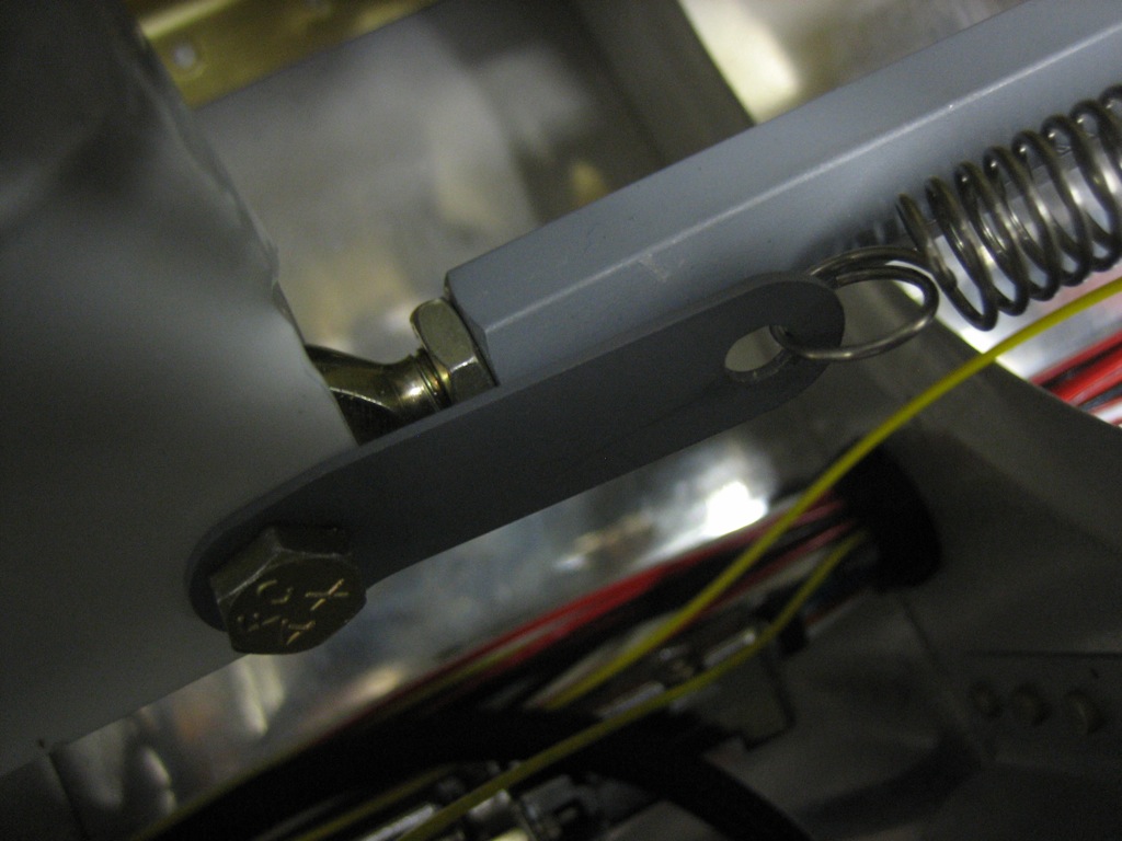
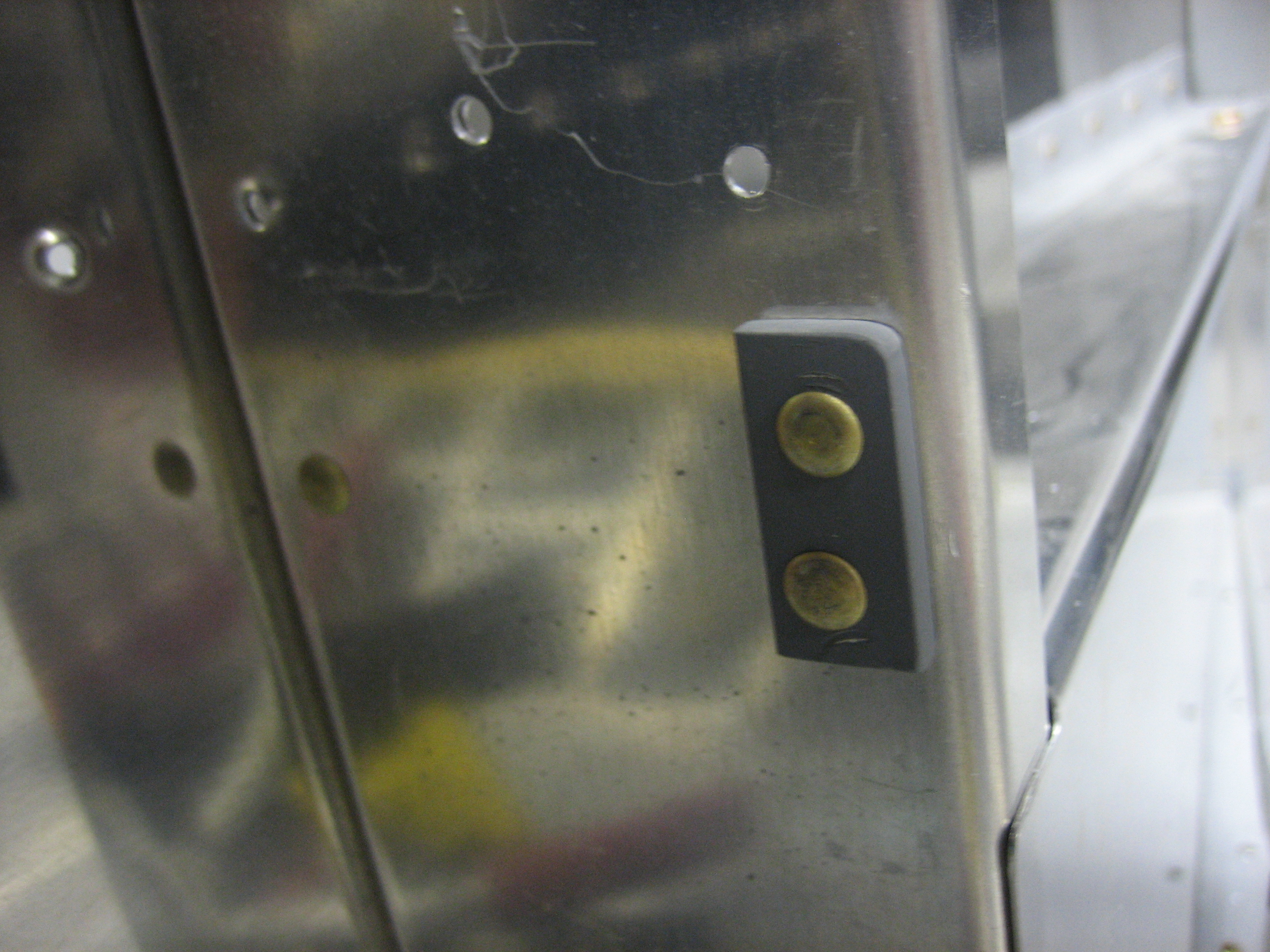
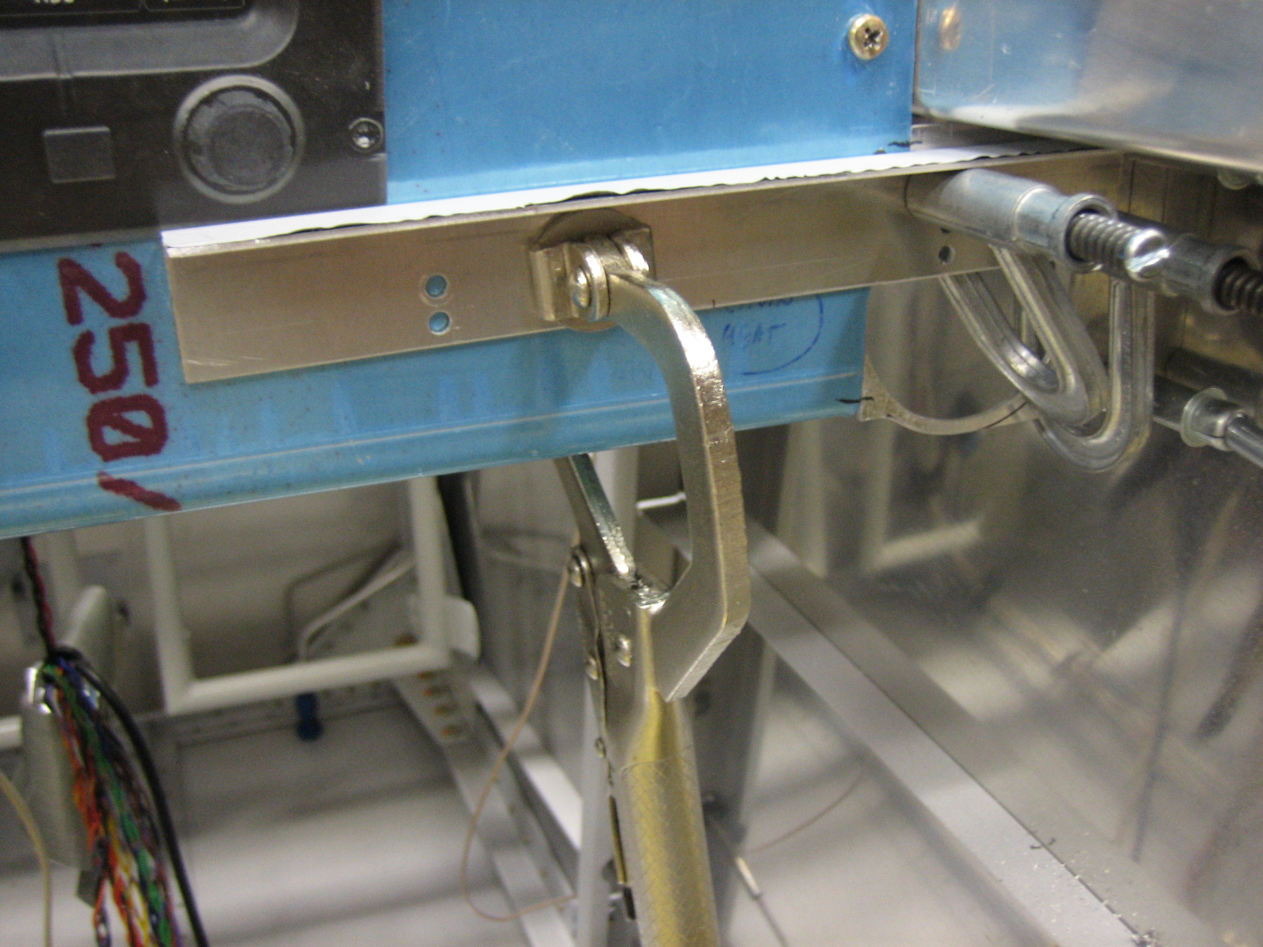
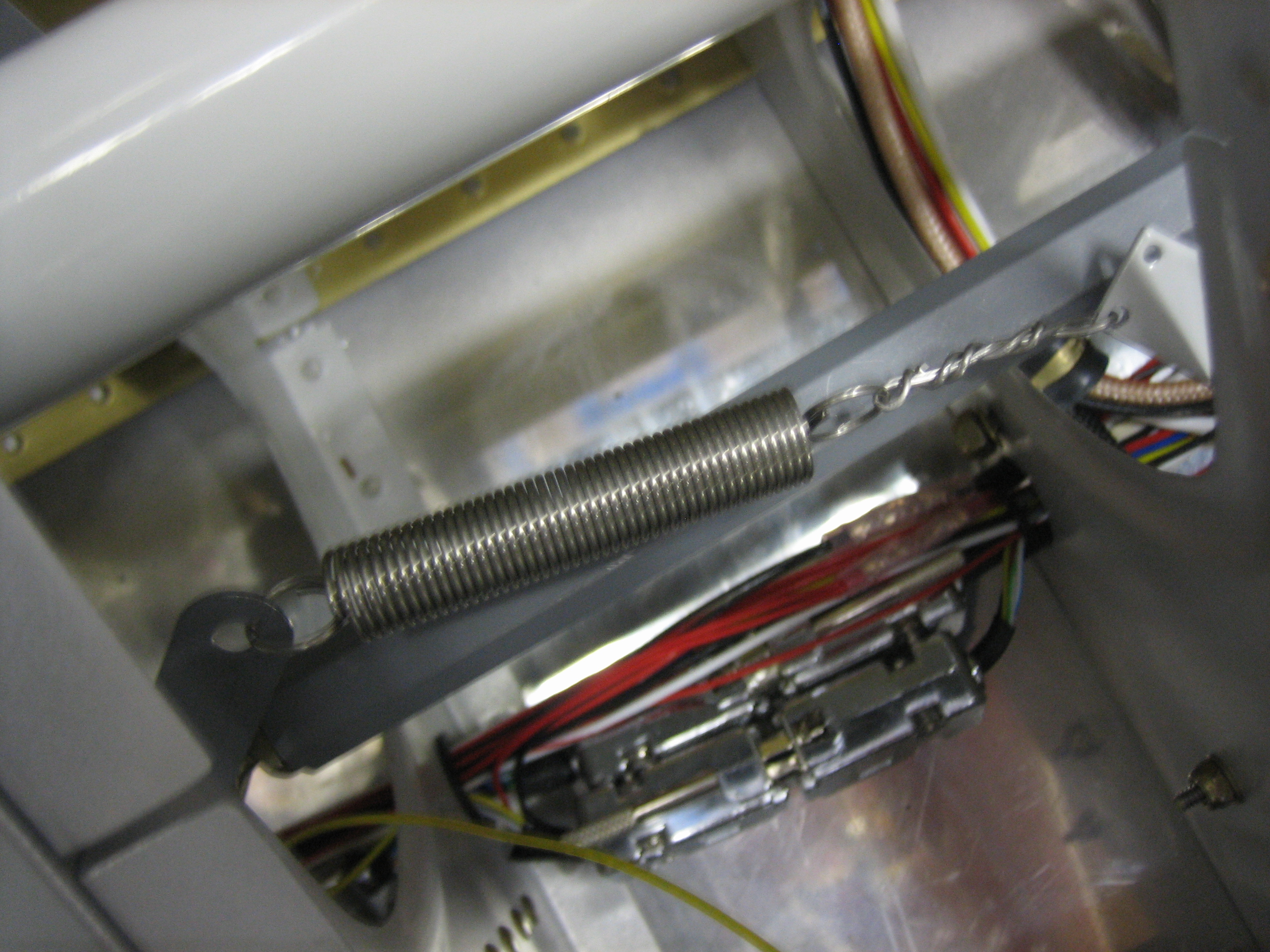
When the stick is in the full forward and left position, the spring is attached to the trim servo arm so that the spring is very slightly extended.  This prevents the spring from ever going slack regardless of the position of the controls.  There will be another spring tying the co-pilot’s stick to the other hole in the trim servo arm.

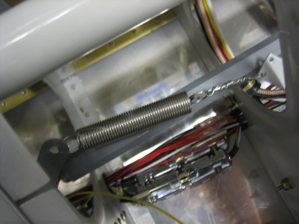
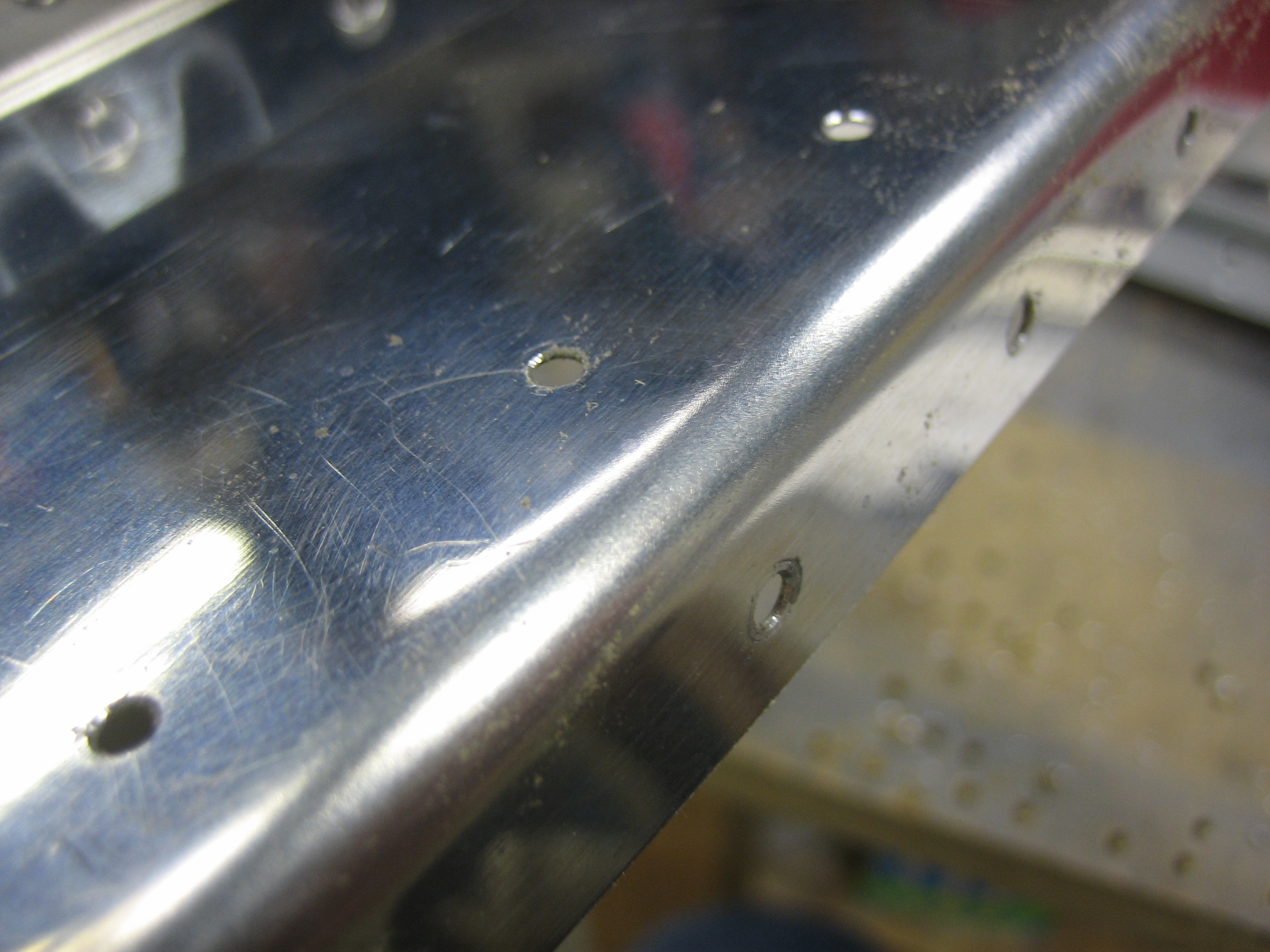
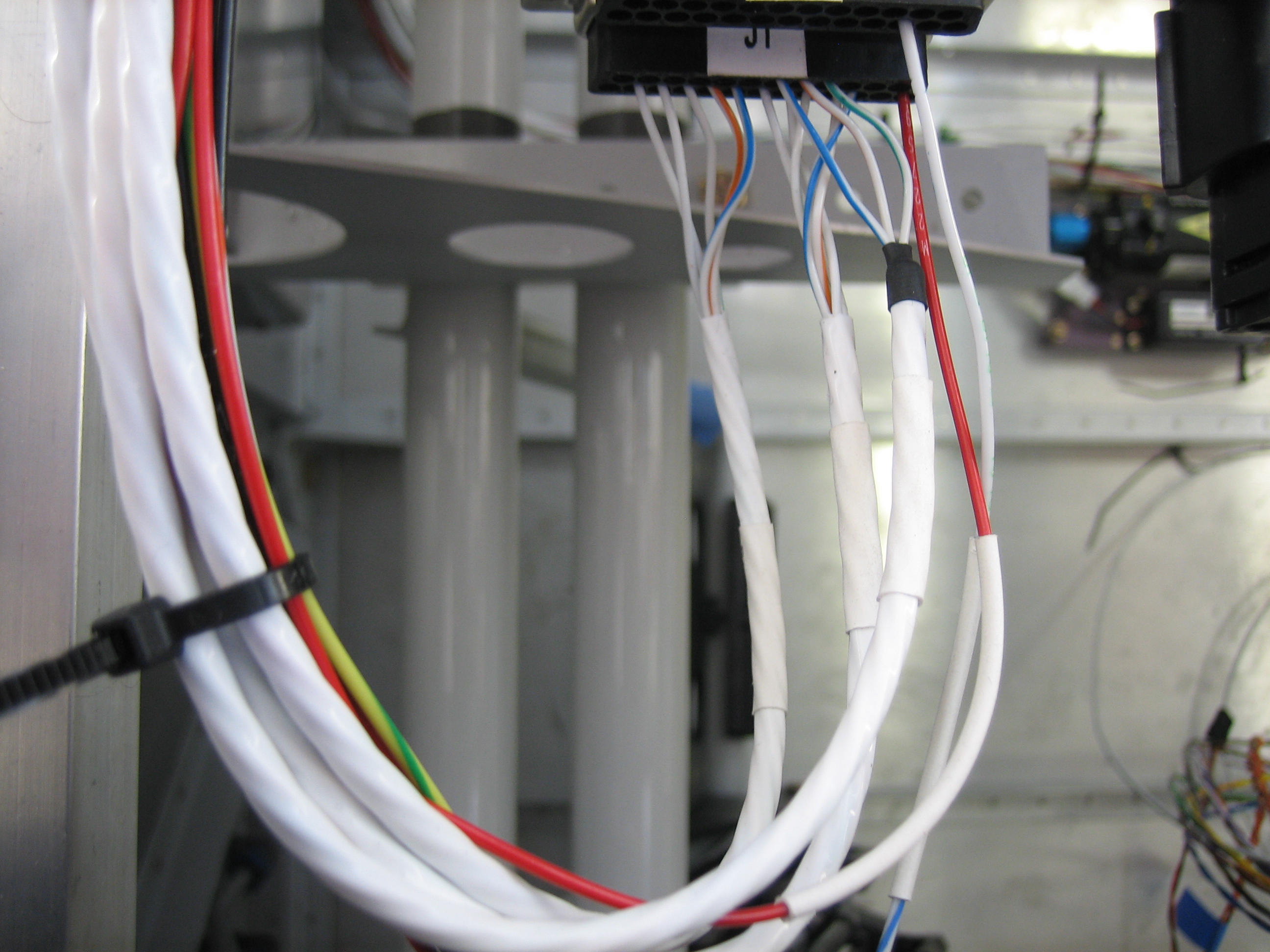
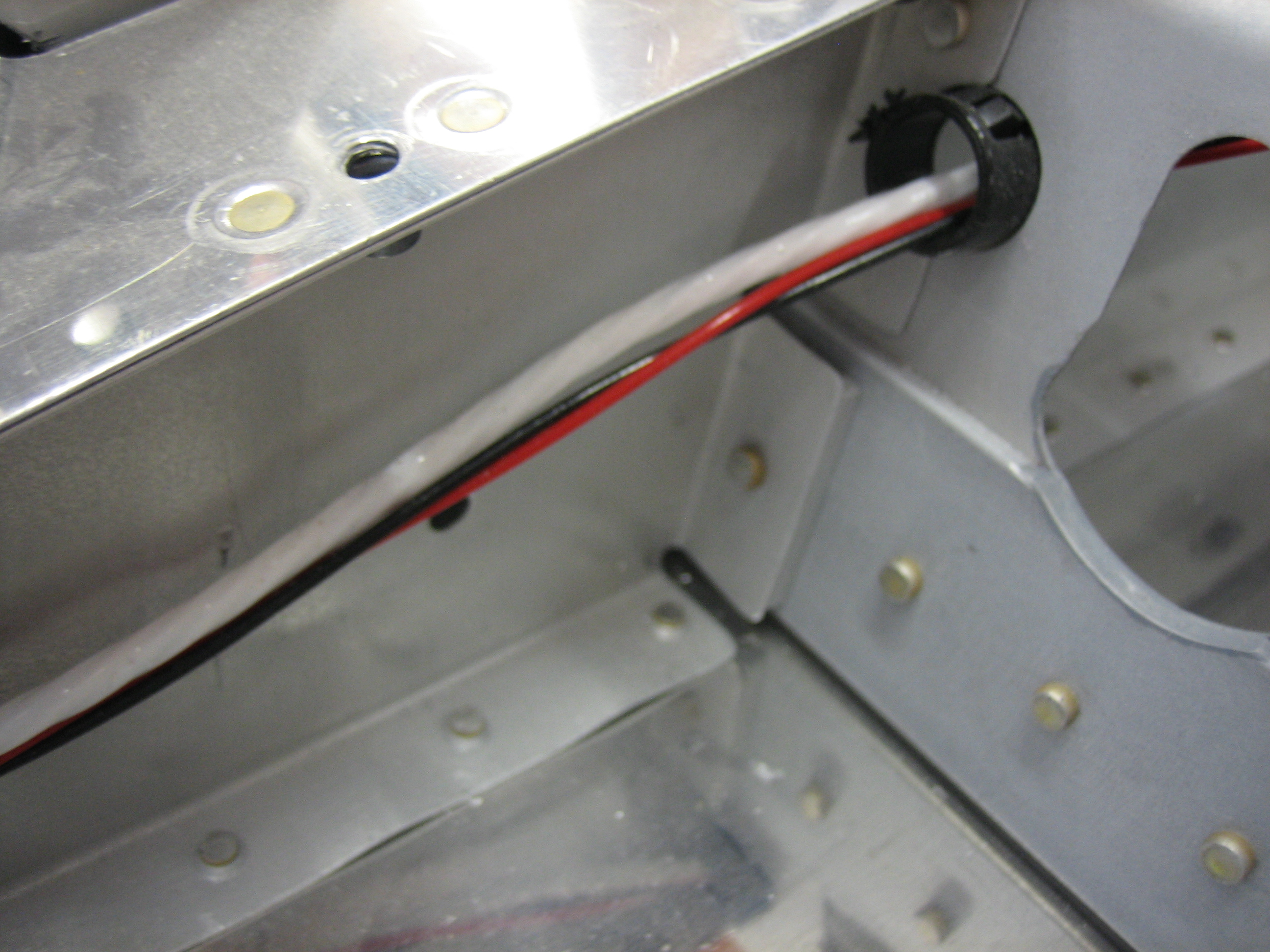
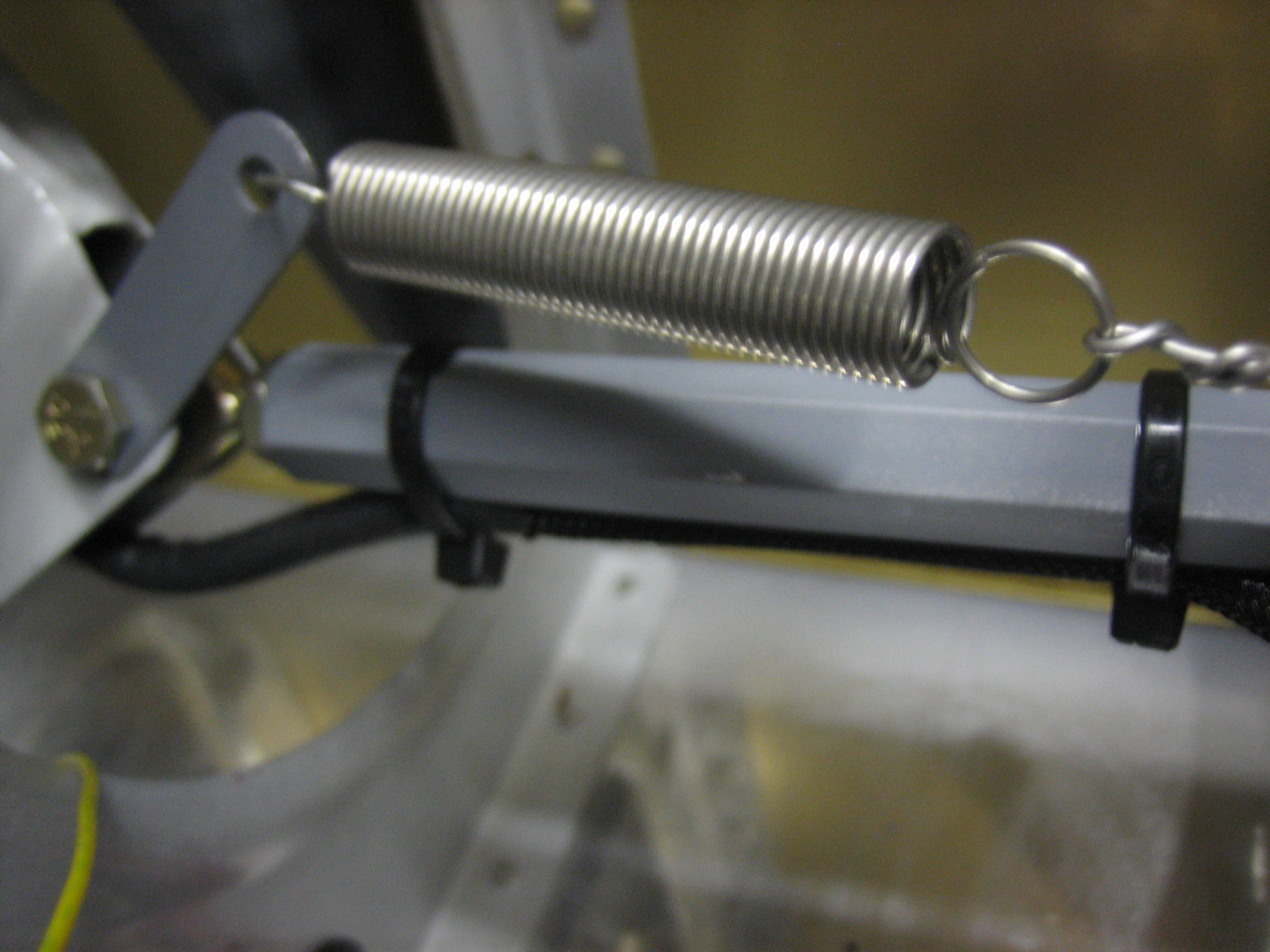
The bundle of wires from the pilot’s stick exits through the bottom (between the bearings) and is tied to the connecting pushrod in a couple of spots to prevent interference with the trim spring and the adjacent rib.  The bay just inboard of the stick will provide room for the wire bundle to flex as the stick is moved.

Finished Aileron Trim and Started Wiring Seat Heaters

I finished the aileron trim by installing the right clip and attaching the spring between the clip and the servo arm with some 0.041″ safety wire.

I adjusted the length of the safety wire so that the sticks naturally rest vertically when the servo arm is in the neutral position.  I ran the trim to both ends and moved the sticks in all directions to ensure that nothing could snag or interfere with the sticks.  I had to adjust the bend in the servo arm slightly to keep the safety wire from interfering with the rib just to the right of center.

Next up, I installed the dimmers for the seat heaters.  The control cable to the right is for the cabin heat, so all of the heat controls are located together.

I prepped the wires and attached them to the dimmers.  It’s too late to run these wires tonight, so I’ll finish these off tomorrow.