Started Cabin Frame

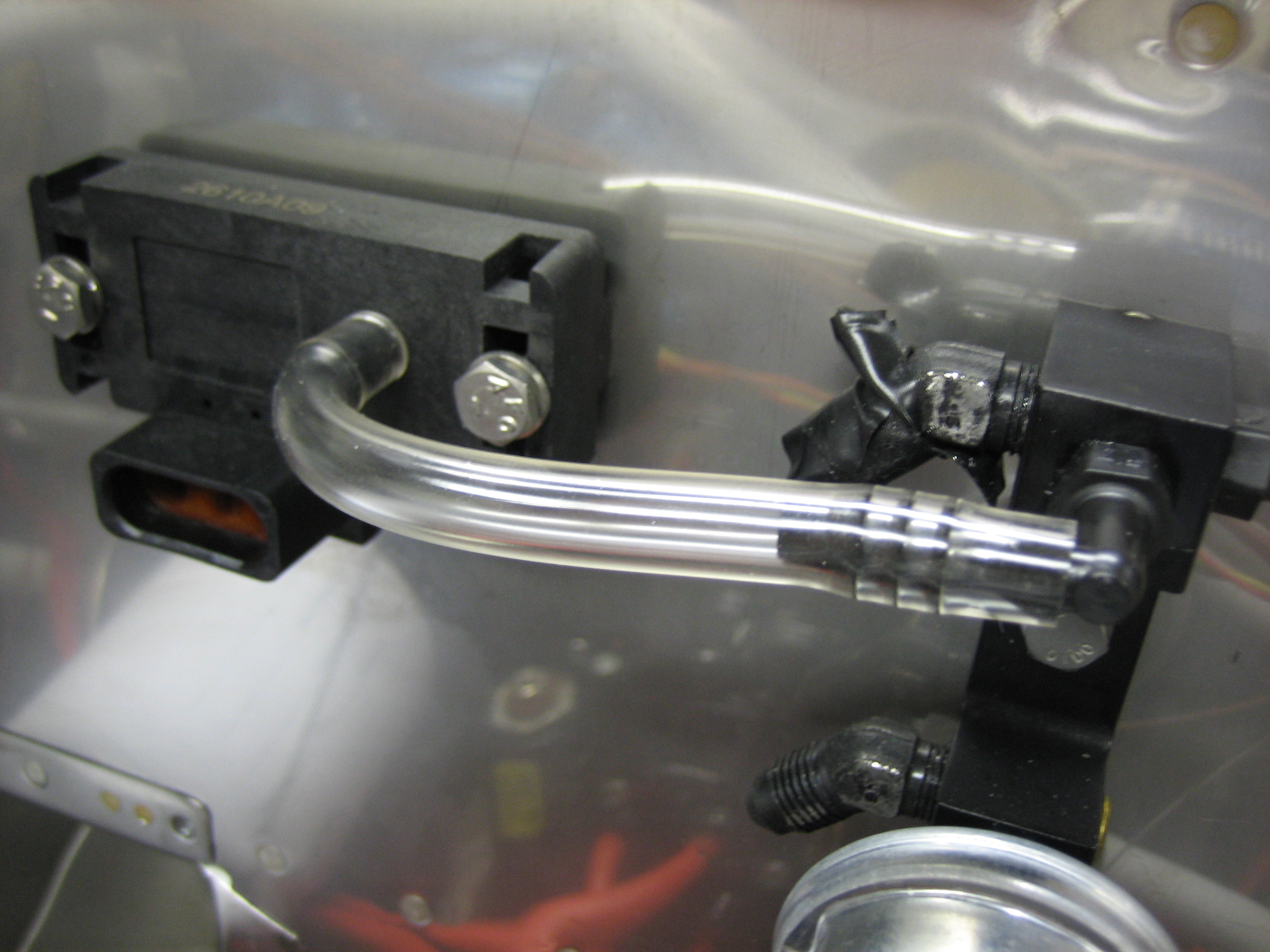
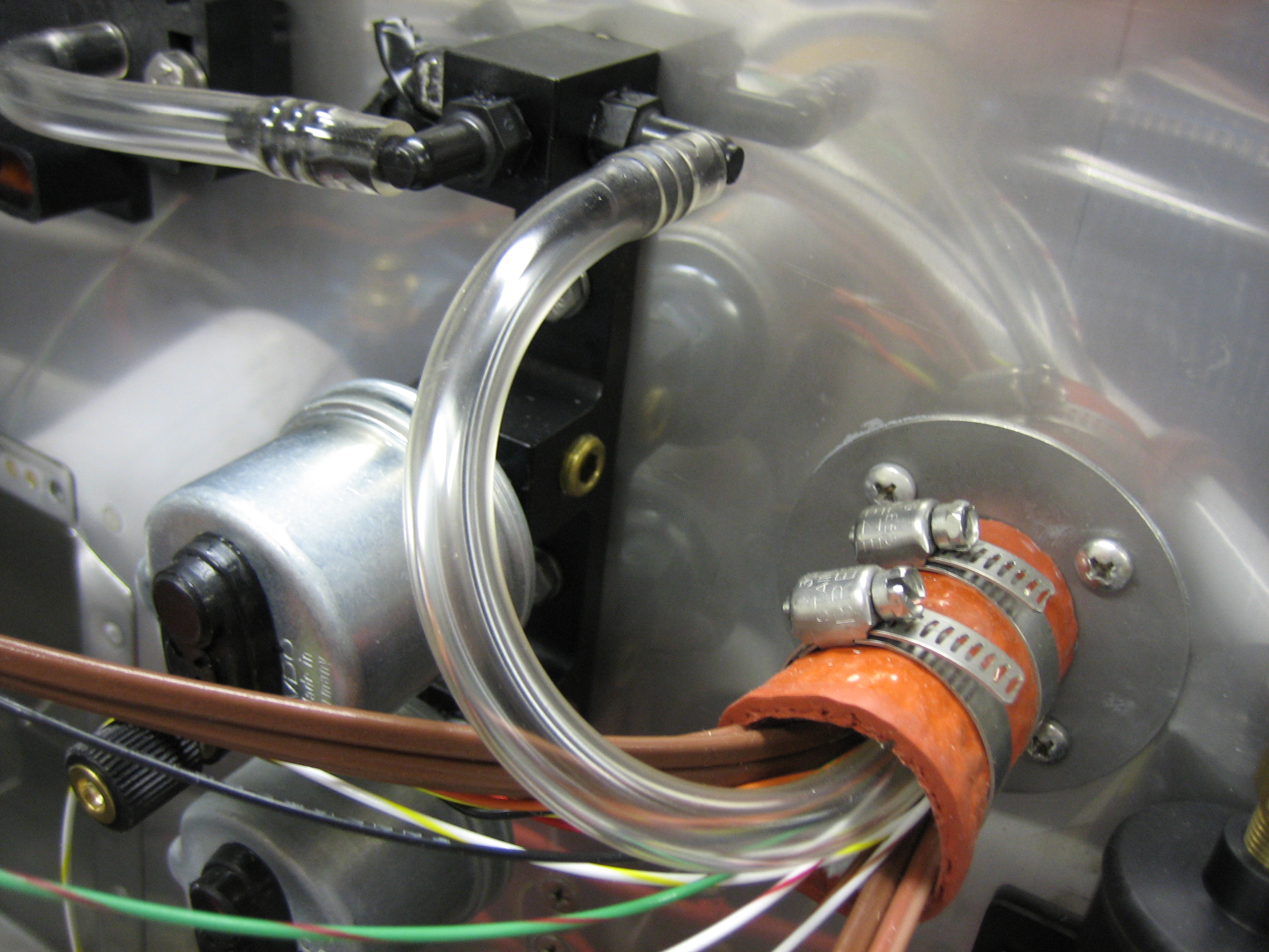
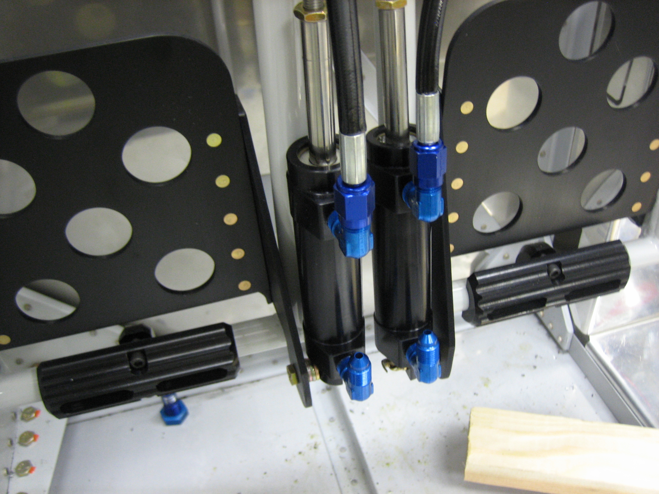
I called Bonaco this morning and put in an order for a few hoses.  I ordered a short hose that will run from the fuel bulkhead on the firewall to the inlet of the engine driven pump.  I also ordered the hose that run from the outlet of the engine driven pump to the fuel servo.  This hose needed 45º fittings on each end with 270º clocking.  We’ll see soon if I measured correctly.  I also picked up the hoses that run from the brake fluid reservoir down to the master cylinders.  Since all of my other brake components are black, I had Brett do these in black as well.  Finally, I ordered the brake lines that go from the bulkhead fittings on the firewall down to the wheel cylinders.  Van’s plans call for rigid lines from the bulkheads down to the wheel cylinders with generous service loops inside the wheel pants to allow for flex and vibration.  This is a notorious source of cracking though due to flex in the aluminum line.  Since aluminum doesn’t have a fatigue limit, even minor flexing will eventually result in failure.  Even the MIL-PRF-83282D brake fluid (which is a huge improvement over the old MIL-H-5606 fluid) is flammable, so a brake line failure can really ruin your day.  Some people run rigid tubing down the leg and transition to flex line near the wheel cylinder, but the whole gear leg flexes when on the ground, so this really doesn’t eliminate the line flex.

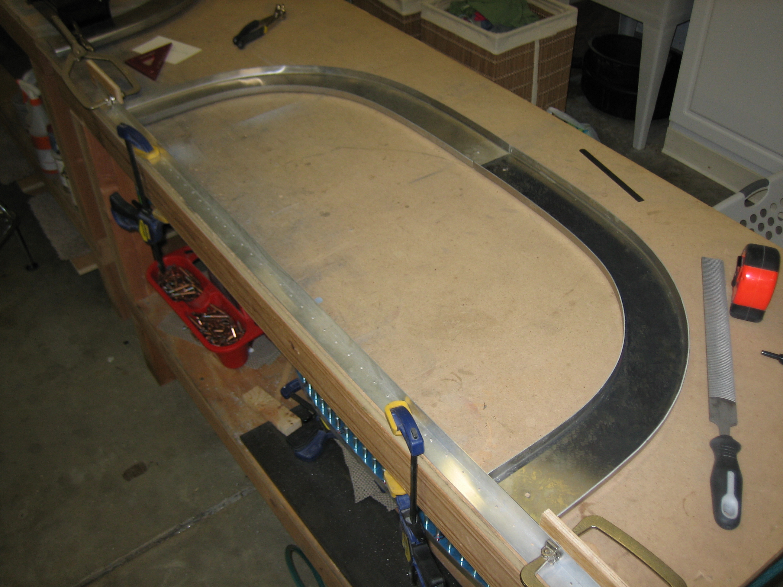
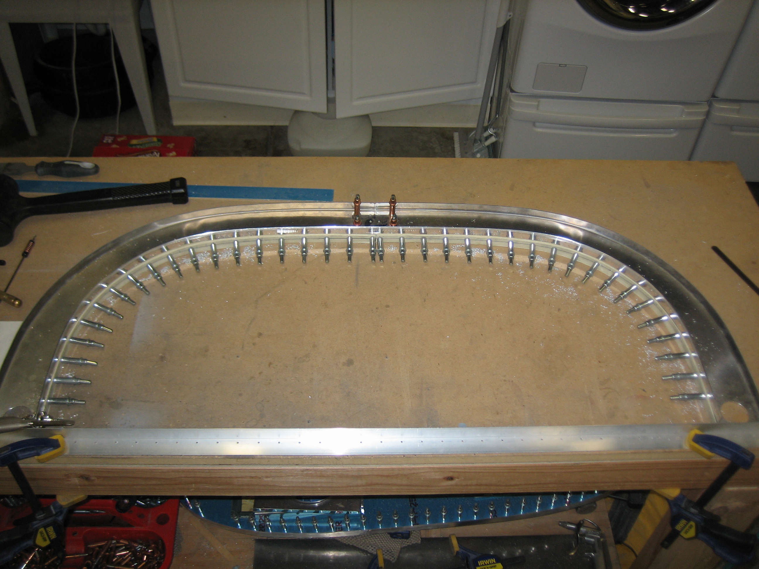
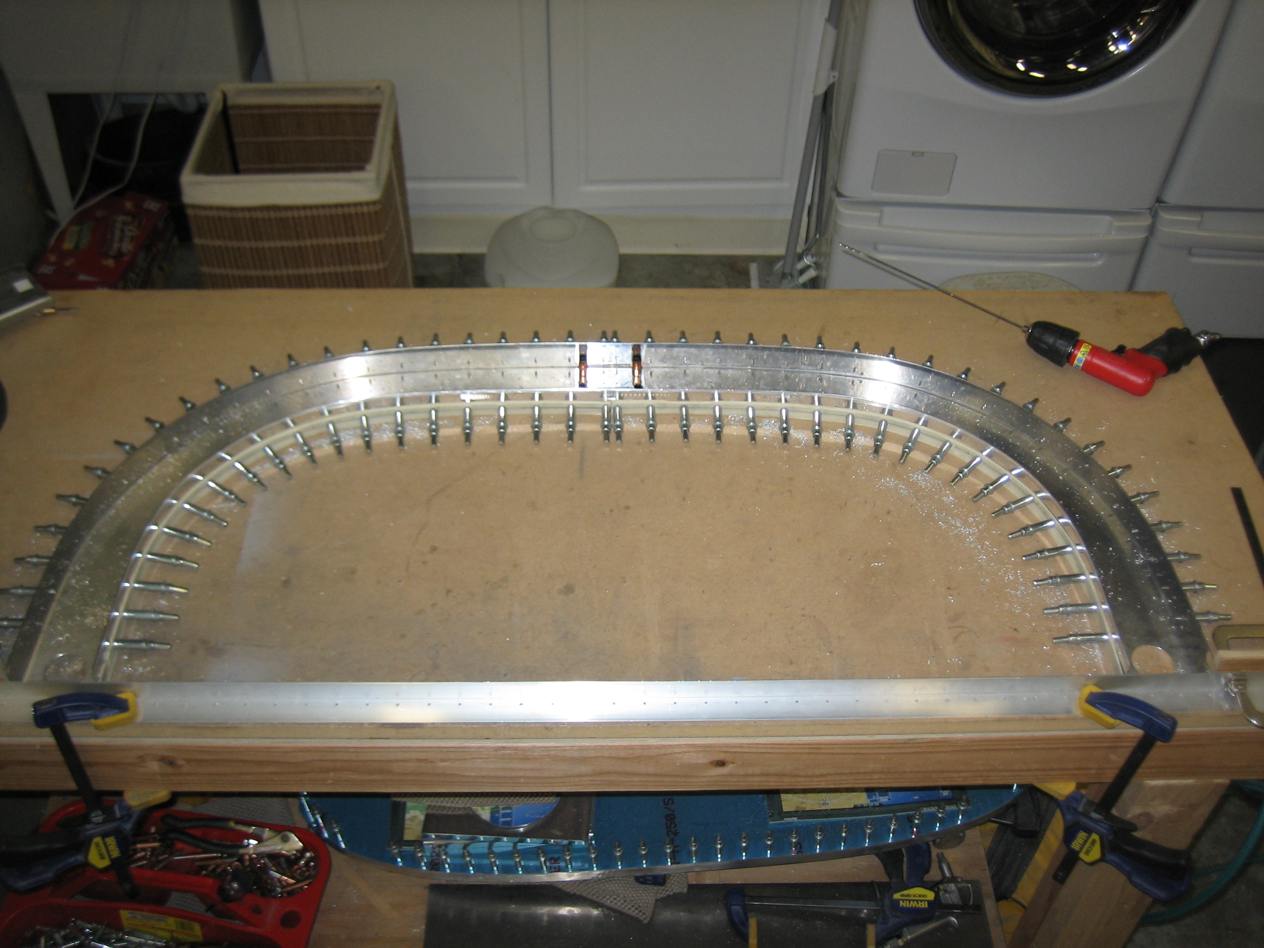
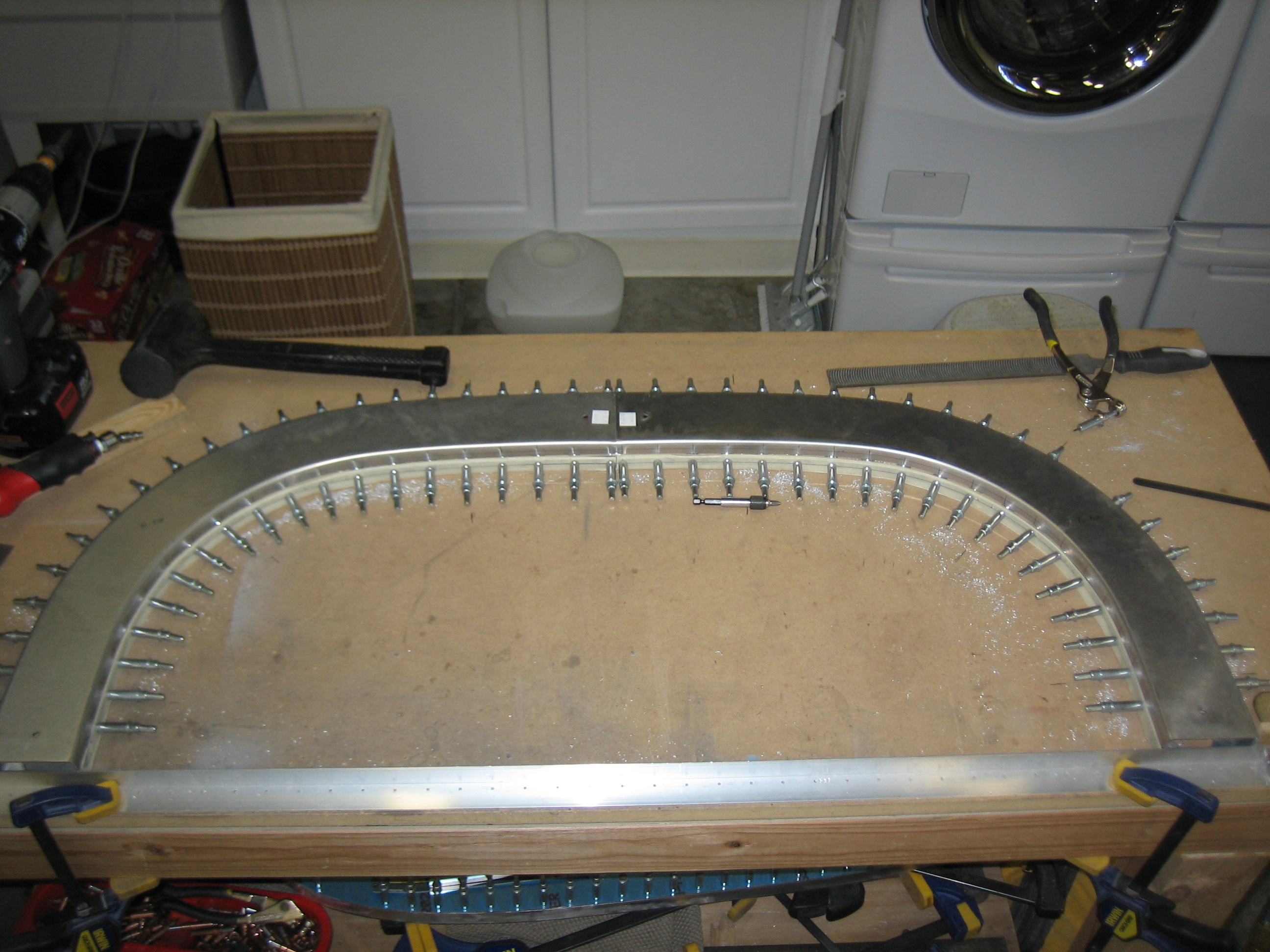
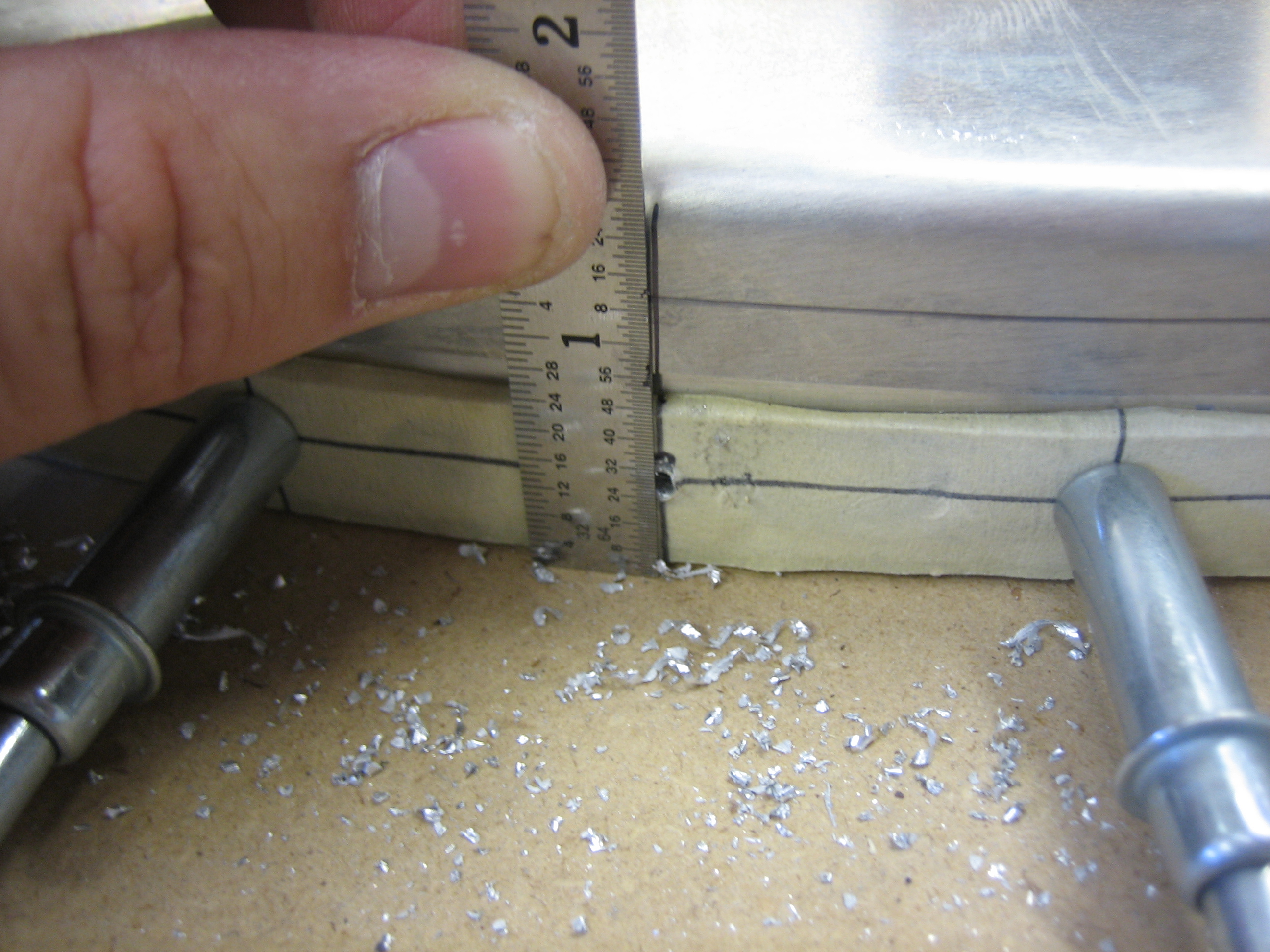
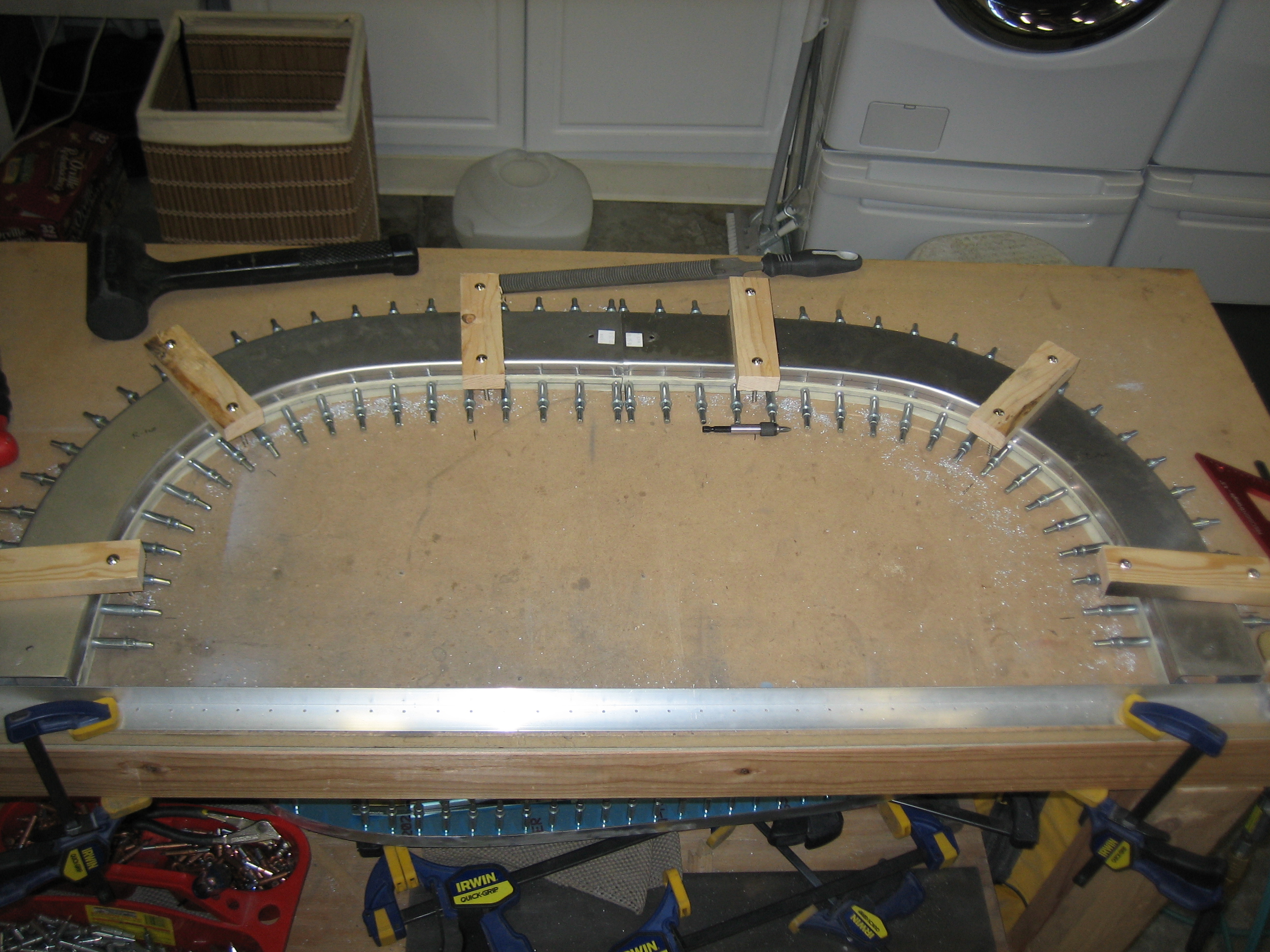
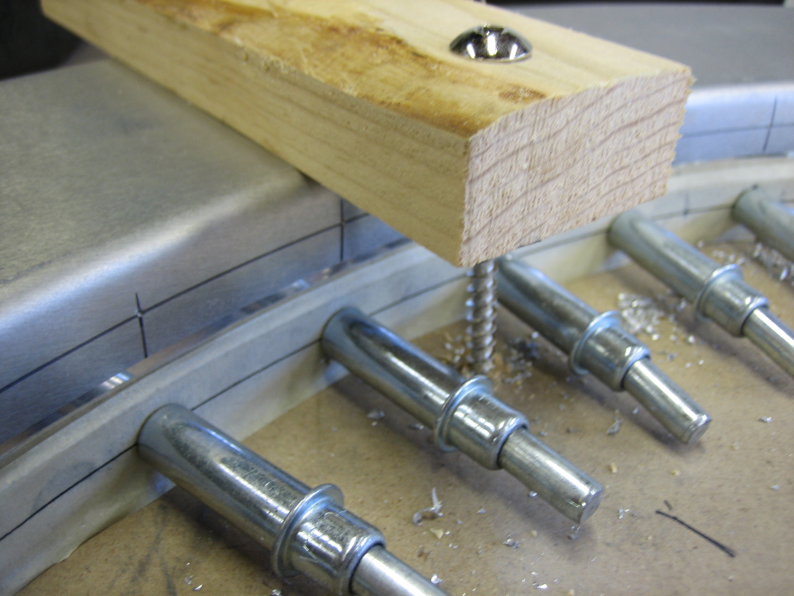
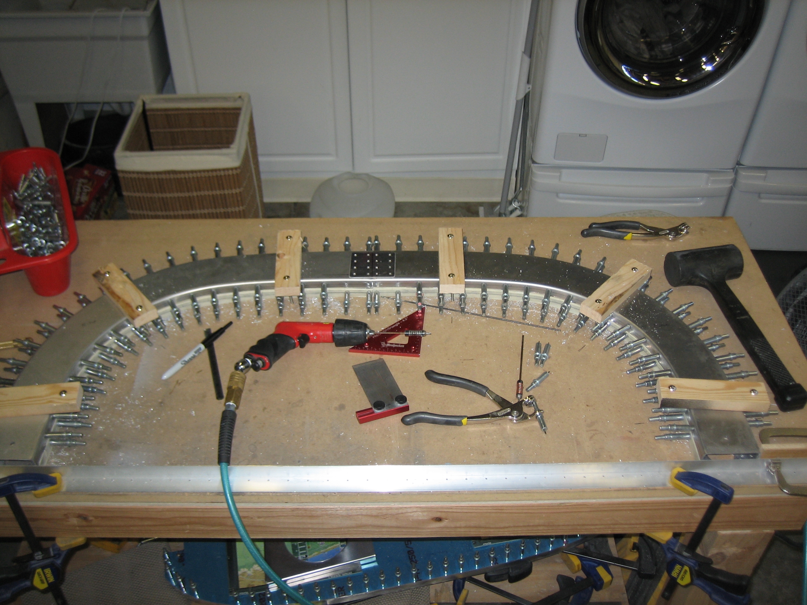
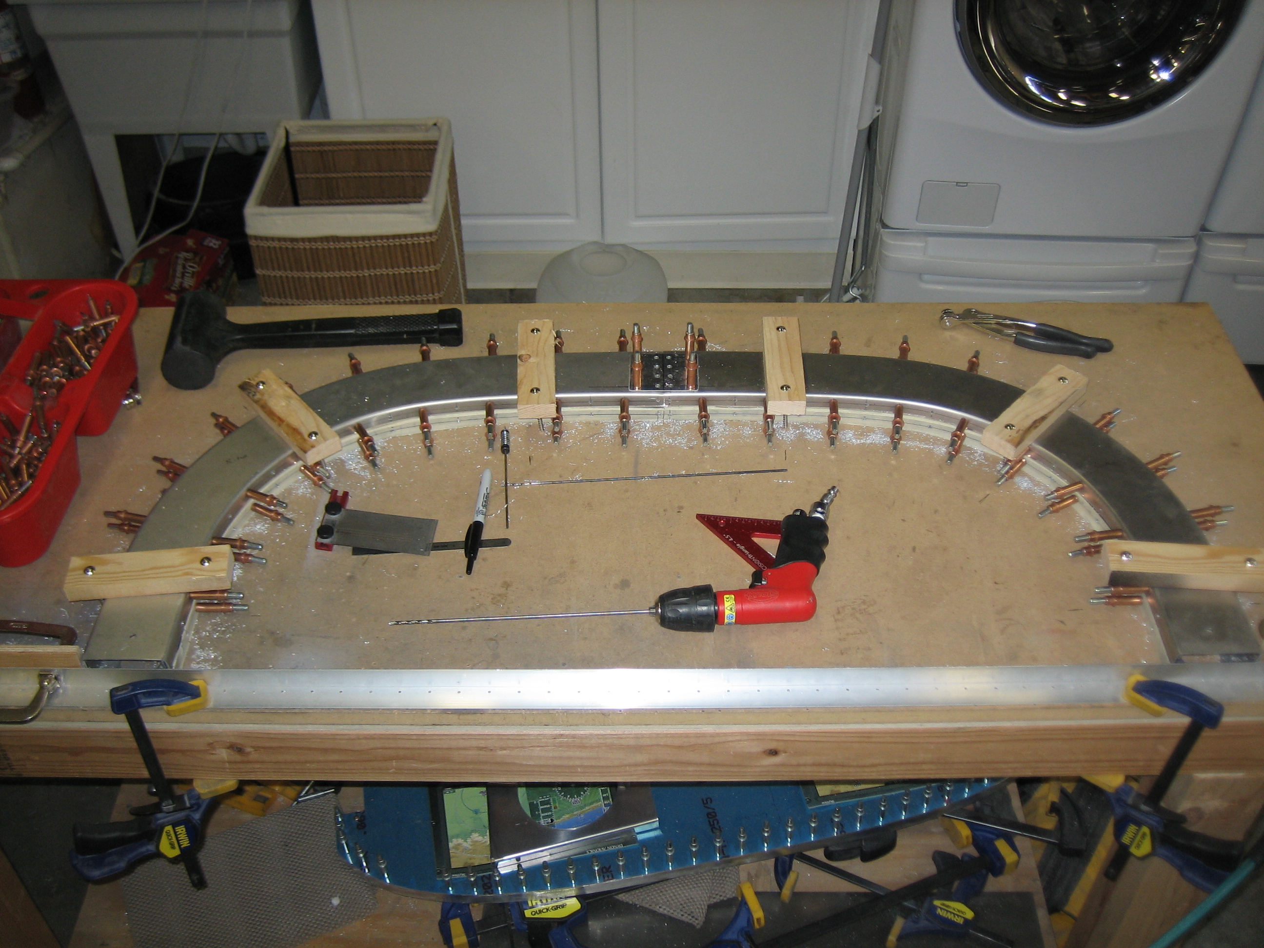
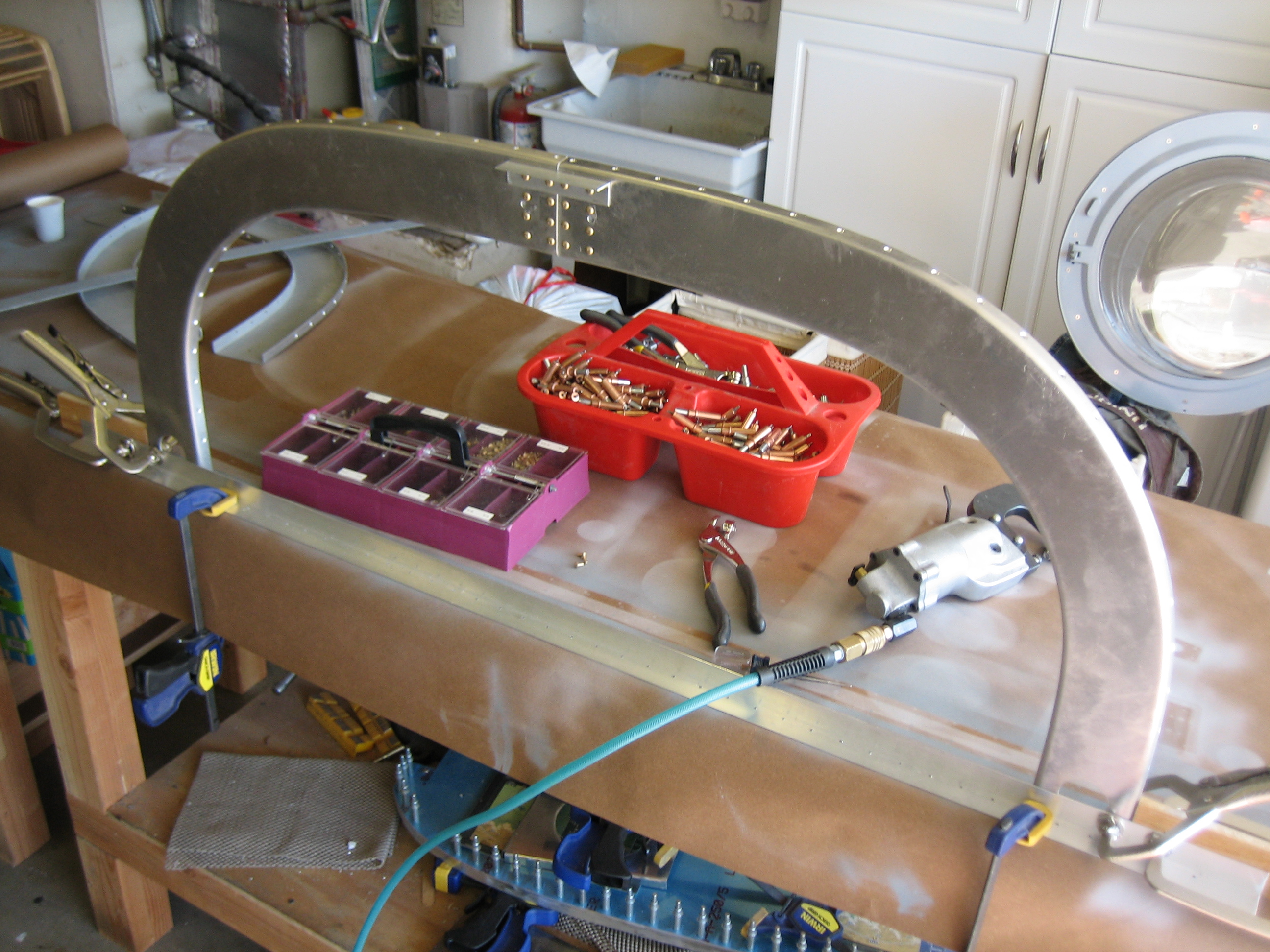
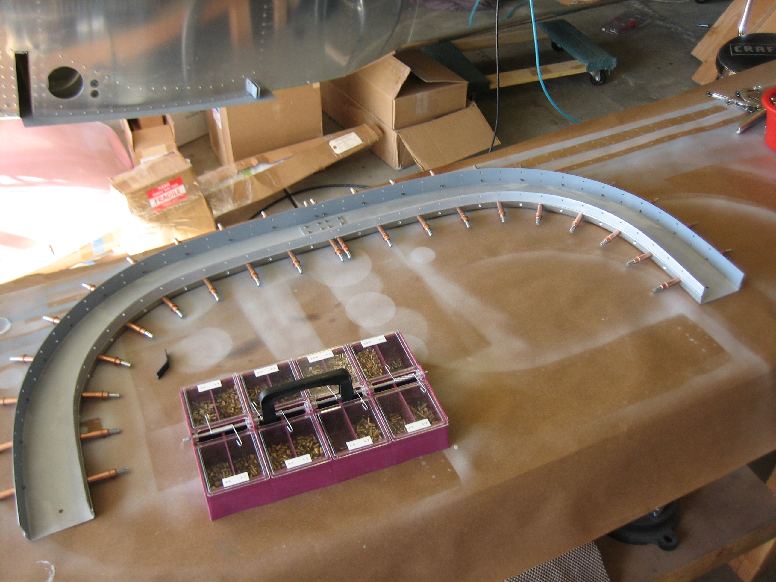
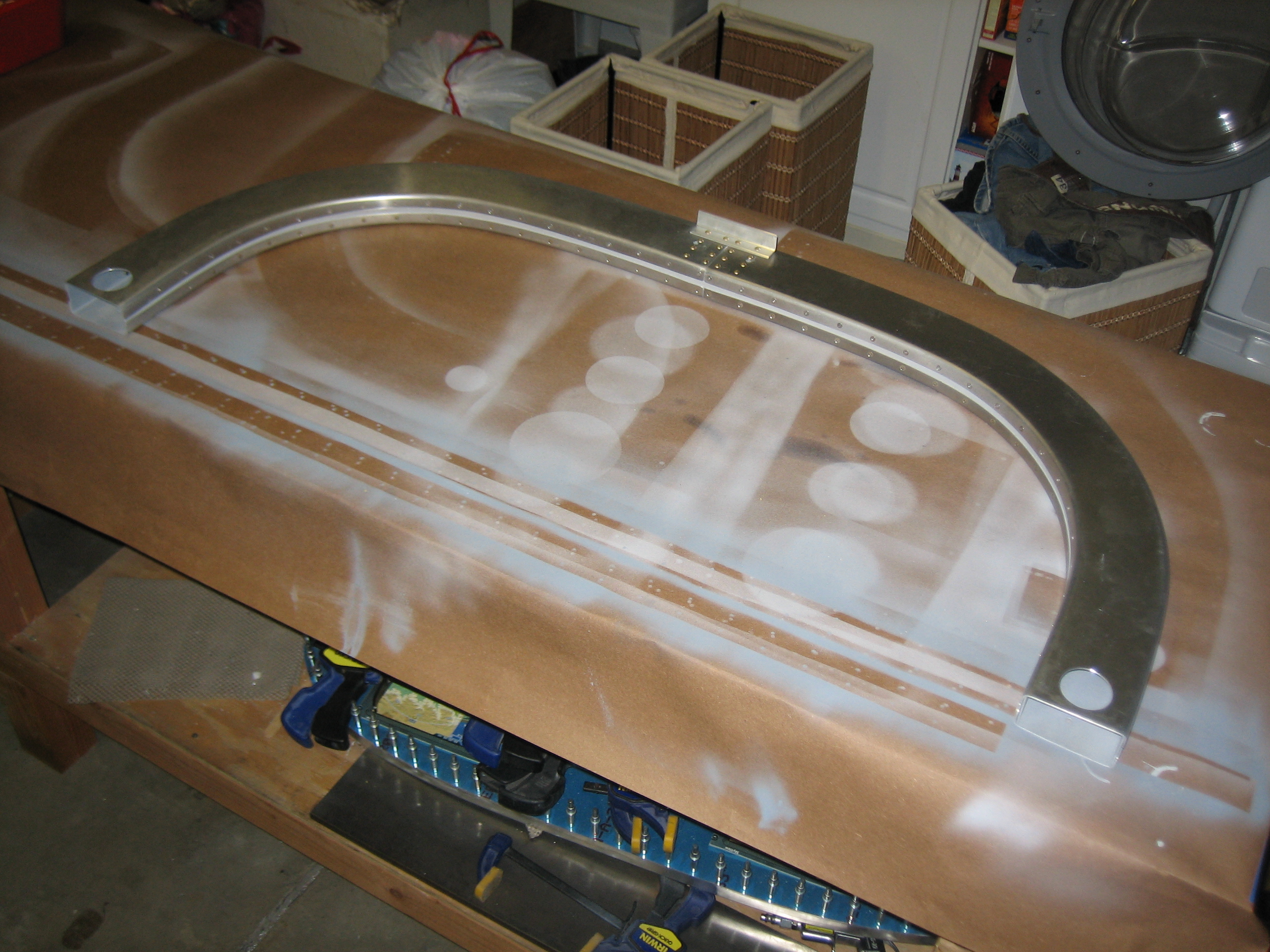
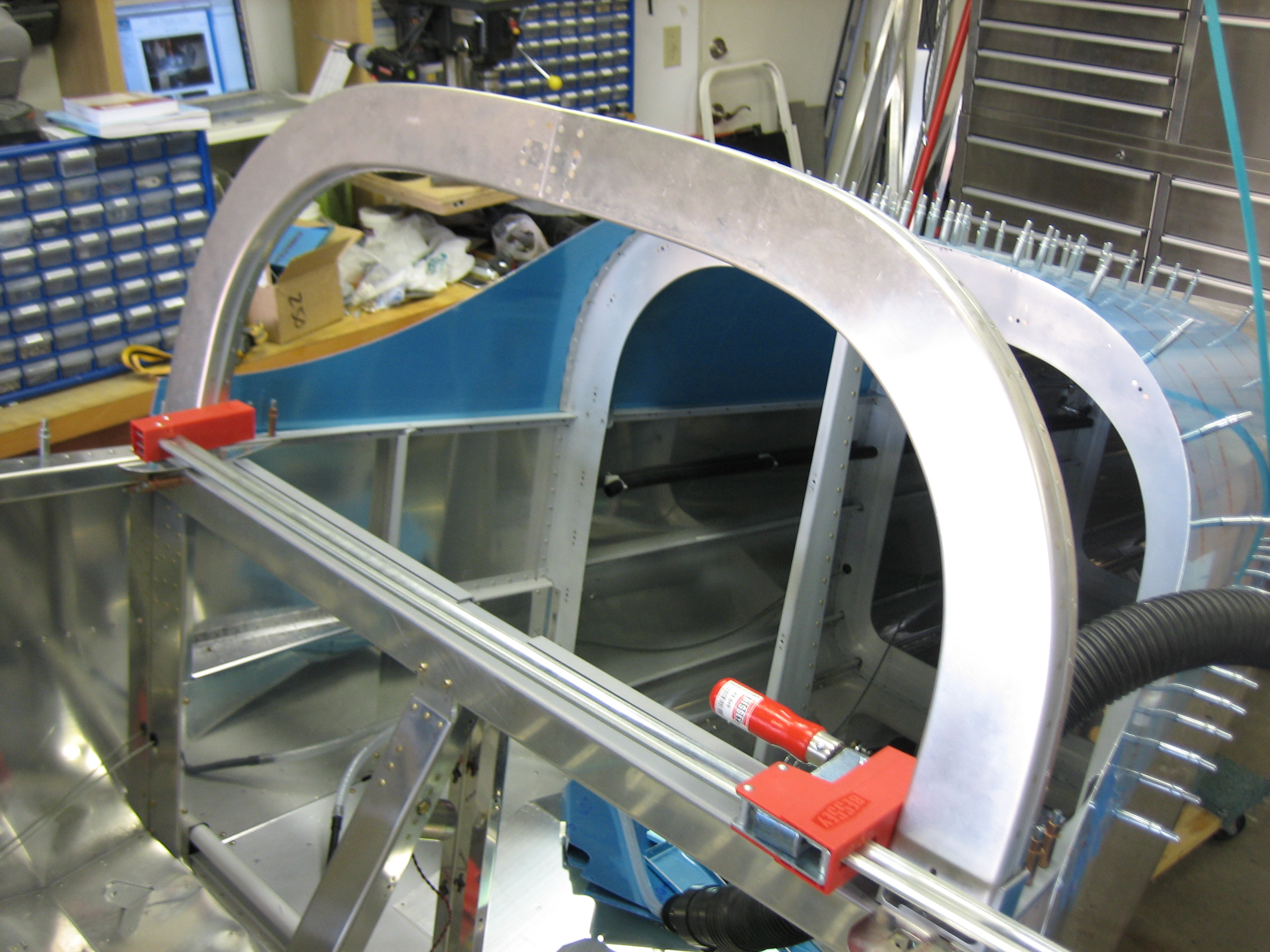
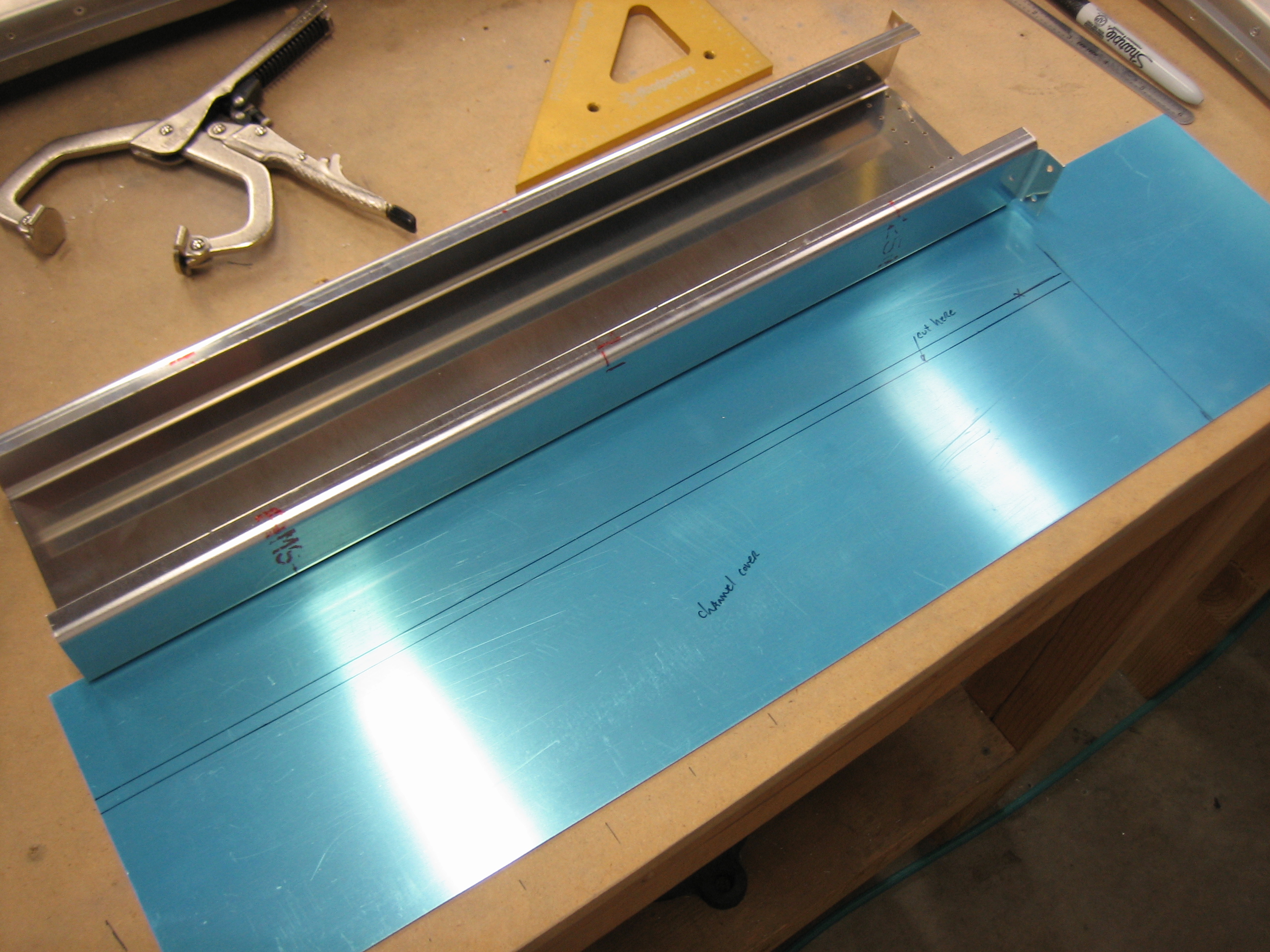
Since I’m waiting on an order from Aircraft Spruce for new 5052 brake lines, I decided to get started on the cabin frame.  I clamped a straight edge to the bench and then clamped wooden blocks to the vertical legs to define the overall width of the frame.

The center seam was pretty close, but I touched it up with the vixen file to get the edges perfectly aligned.

The bottom edges were not even close to parallel with the guide angle, so I marked and trimmed them flush.

Here is the result.  It looks like there is a shadow here, but that’s just the black line I drew parallel with the guide angle.

The canopy frame is about 1/16″ taller than the plans specify, but I’m going to leave this.  In fact, I’ll likely try to cheat the canopy up another 1/4″ or more in final fitting.  This will directly translate to more headroom in the plane which I’ve heard is a problem for someone my size.

Last up tonight, I drilled the 1.5″ holes in the bottom end of the aft members the roll bar.  This is to allow access to the bolts that hold the cabin frame down to the seat back support.


Manifold Pressure Lines, Cabin Frame Joint

An order from Aircraft Spruce showed up today with some 1/4″ ID tygon tubing.  I cut a short piece to connect one outlet of the pressure transducer manifold port to the Dynon manifold pressure sensor.

I used the remaining tubing to connect to the other outlet and ran this through the firewall passthrough.  Inside the fuselage, I’ll transition from 1/4″ ID tubing to 1/8″ ID tubing for the connection to the Lightspeed electronic ignition.

Finally, I fabricated the splice plates for the cabin frame halves.  The pieces that Vans provided for this were not square.  The two short edges were not perpendicular to the long edges.  I laid the holes out square though since the rivets will be seen on the outside of the cabin frame.

Worked on Cabin Frame

I rounded over the edges of the canopy frame joint strips.  These join the front and back halves of the cabin frame.  The radius is necessary so that the halves can be pulled tightly together.

I also put a strip of masking tape around the inside edge and marked for the lowest hole.  I’ll use a rivet fan to lay out holes along this strip and then use it to drill the holes evenly along the inside edge of the canopy frame.

Started Drilling Cabin Frame

I didn’t have much time to work on the plane today, but I did manage to get the inner cabin frame joint strip drilled to the aft channel.  I’m only drilling these out to #40 now, but they’ll get drilled out to #30 once everything is fit.

Finished Drilling Aft Cabin Frame Channel

My buddy Andre came over today to help me rivet the aft top skin.  I got the honors of crawling into the tailcone to buck these rivets.  I’m a pretty big guy (6’4″ and 235 lbs), so this was a pretty tight fit and I was pretty uncomfortable by the end.  After knocking out all of the riveting, I also torqued and sealed the shoulder harness attach strap bolts.  I didn’t want to have to climb back in here again if I could help it.

Here’s the finished product. The forward row of holes (where the clecos are still present) is left open since the forward skin also attaches here.

Later in the evening after everyone else had gone to bed, I drilled the outer cabin frame joint strip drilled to the aft channel.  I need to make some spacers to temporarily fit between the forward and aft channels to ensure proper spacing.

Finished Drilling Cabin Frame

I fit the forward channels and filed the ends to ensure the center seam was tight.

I then transferred the lower hole locations to the upper channels.

I then fabricated some spacers out of scrap 2x2s that were sanded down to 1.375″ thick.  Since I’m fabricating the cabin frame flat on my bench, I used some scrap 1x2s and long screws to clamp the cabin frame down tight to the bench.

Here’s a closeup showing how the scrap wood is screwed directly to the bench.  These are positioned directly over the internal spacers.  This keeps the cabin frame thickness exactly 1.5″.

Finally, the top channel was drilled.

I then positioned the forward splice place and match drilled the channels to it.  This will eventually be installed on the inside of the channel.

Now that everything was positioned and drilled, I went back through and enlarged all holes to #30.

While I was doing that, Andre stopped by and fabricated a number of the attach angles.  These are used to attach the cabin frame to the fuselage.

Started Countersinking Cabin Frame

I disassembled and deburred all of the channel holes in the cabin frame.  I then started working on countersinking all of the necessary holes.  These are the ones in the channels that are used to rivet on the splice plates.

I also did all of the outer holes along the forward channels.  These are a little trickier since the curve prevents using the countersink cage to set the depth.  Basically, these all need to be done freehand which makes these holes fairly time consuming.

Installed Master Cylinder Fittings

I received the AN822-3D fittings from Aircraft Spruce today and installed them in the master cylinders.  I then installed the hoses from the brake fluid reservoirs onto the upper fittings.  I searched everywhere for these fittings in black, but could only find them in blue.  I did find AN822-4D fittings in black, but I didn’t want to use 1/4″ lines here if I could avoid it.  I even briefly thought about having some re-anodized in black, but that would be ludicrously expensive and I couldn’t have re-anodized the hose end fittings.  I also replaced the AN816-4D fittings I previously installed in the parking brake with AN816-3D fittings.  Finally, I measured for the final brake hoses from the master cylinders to the parking brake.  I need to put in another order to Bonaco soon for these hoses as well as the manifold pressure hose and possibly the remaining fuel hoses.

Finished Cabin Frame

I finished deburring and countersinking the cabin frame components this morning.  When our two year old went down for her nap, I came back out and primed all of the components and then started assembly.

I’ve seen several builders complain that their cabin frames came out wider or narrower than intended.  I think this is likely due to the slight amount of play in the splice plate rivet holes.  Although the play is tiny at the splice plate (in the middle joining the left and right halves of each channel), the amount of play at the ends of the channel will be much more (easily 1/4″ or more).  To help ensure that this doesn’t happen to me, I clamped the channels back in the sizing jig before squeezing the splice plate rivets.

After the front and back channels are joined with the splice plates, the straps can be clecoed into the forward channel so that solid rivets can be squeezed here.  After all solid rivets are squeezed, the aft channel can be installed and blind rivets can be squeezed.

I didn’t get any more in process pictures, but here’s the completed cabin frame.

Here you can see the solid rivets in the forward channel (lower) and blind rivets in the aft channel (upper).  After everything was riveted, I measure the channel and I was only 1/32″ narrower than the plans called for.  This appears to be more accurate than most people end up with.

Started Mounting Cabin Frame

I started today by fitting the attach angles to the bottom of the cabin frame.  These two angles are clamped to the outer edges of the channels and then drilled to each other.  After these were drilled, I countersunk the bottom face and riveted them together.

To ensure that the angles were mounted in the right position, I clamped some scrap angle to the longerons with some pieces of hinge material underneath to tip the angle back to match the slope of the side skin.

Here you can see that the angle is flush with the skin.

I then used some scrap 0.063″ aluminum (the thickness of the cabin frame channels) to space the attach angles back so that the forward edge of the cabin frame will be flush with the side skin.

I then drilled/reamed the attach angles to the rest of the structure.

I then temporarily installed the cabin frame to see how it fit.  As I measured yesterday, it was slightly narrow, but a small amount of pressure from a clamp could spread it into position.  The attach angles hang over the sides of the longerons.  I marked the overhang and then removed the attach angles to start filing them down.

I took a break from the filing and laid out a cover for the cabin frame channel.  I’m going to be installing a cover on this channel so that I can install a cabin light into it.