Installed Tires and Tubes

My wheels and tires/tubes showed up today.  I’m using the Grove wheels which have a much higher heat energy absorption than the stock wheels and are actually lighter because they’re magnesium.  I also went with the Condor 6 ply tires and Michelin AirStop tubes because both were highly recommended on vansairforce.net.  The tire on the left shows the outside of the wheel.  The one on the right shows the inside with the disc brake.

I also ordered the Grove parking brake.

The wheels came with the brake cylinders and mounting brackets.

Drilled Crotch Strap Mounting Hole and Installed Flap Motor

I have been trying to decide between the Hookers at $410/seat (with the rotary latch) and the Crow at $160/seat for quite some time.  Safety wise, I think they’re comparable, but there are several drawbacks with the Crows.  There are only four colors of webbing to chose from as well as four colors of pads to chose from, none of which match my interior very closely.  Also, the rotary latch is quite thick and I’m worried that it will interfere with the stick.  The Hookers come in 14 colors, with 20 color choices for pads and trim, and the rotary latch is much thinner.  The only drawback is the price.  What finally clinched it for me is that I found out that Classic Aero Designs (who will be making my interior) sells the Hookers and will make matching leather pads using the same material that my seats are made of.  With that decision made, I went ahead and drilled/reamed a 1/4″ hole, 1/2″ below the outer holes in each crotch strap bracket.  I can’t use the stock Van’s hole position because the Hooker brackets are longer than the Van’s brackets.

I also primed and riveted on the inner flap motor mount bracket and bolted the flap motor in place.  This bolt is secured with a cotter pin since you can’t torque it down since that would bind the motor and it needs to pivot on this bolt.  I used some TriFlow lubricant here to keep everything moving smoothly.  This is the same lubricant that I will be using on all of the rod ends throughout the plane.

Installed Seat Belt Cables

I decided to go ahead and install the seat belt cables and partially bolt the bracket in place.  The middle of the three AN3 bolts has been torqued and sealed.  The other two would interfere with side rivets, so they’ll be installed after the top is riveted on.  I also put the AN4 bolt that attaches the cable and torqued/sealed it.

I did this now, because it was trivial to ensure that the cable was aligned with the baggage wall pass through. If I waited to do this after installing the top skin, I’d be climbing back in the tail to tweak the alignment.

Worked on Forward Covers and Fuel Selector

I installed the baffle in the vertical portion of the front cover (just below where the air vents are in the cover).  I didn’t get a picture of it, but it needs to be match drilled and riveted along with a handful of nutplates.

I also installed the fuel selector mounting bracket and cover that ties the bracket and lower cover together.

I was planning on cutting off the angled triangular portion since I’m not using the manual elevator trim.  I noticed however that that would leave a large gap between the fuel selector bracket and the vertical cover.  Instead, I flipped the bracket over and will cut off the triangular flange slightly forward of the bend to cover the gap.

Since the lower portion of the vertical cover has the forward face removed for the fuel pump, I won’t use the lower two #19 holes to tie the two pieces together.  This means I can move the lower cover back to eliminate the gap between the lower cover and the spar forward covers.  I started trying to lay out the holes through the floor stiffeners that attach the lower cover, but the aft holes will also attach the fuel pump mounting bracket, so I want to make sure that it position first.

The Andair fuel selector valve intlets can be installed in any cardinal orientation and are held in place with four stainless steel screws.  I used some fuel lube to lubricate the o-rings, and them installed the inlets facing down.

After installing the stainless steel screws, a punch is used to deform the screw into a recess to prevent it from backing out.

I drilled the fuel selector mounting bracket for the fuel selector by first drilling a 1″ hole inthe middle.  I purchased a large unibit knockoff from Harbor Freight a few weeks ago to make larger holes like this.  Unfortunately, it is a complete piece of shit and took several minutes to enlarge this hole from 7/8″ to 1″.  After drilling the large hole, the valve was positioned and the three outer holes are drilled for the mounting screws.

Finally, K1000-08 nutplates can be installed on the valve and the valve can be installed on the mounting bracket.  I spent a little time trying to bend a 3/8″ fuel line to connect the fuel selector outlet to the fuel pump, but I don’t think I can bend the line according to the plans since the bend radius is tighter than my bender allows.  This probably means that I’ll need to install the fuel pump slightly forward of the specified location.

Fabricated Fuel Line Between Selector and Pump

The plans specify that the aft end of the filter be roughly vertically aligned with the fuel selector outlet.  This requires the fuel line to jog backward before turning forward to enter the fuel filter.  The radius on my tubing bender is to large for this to work and still have room to push the fitting back to create the flare on the end.  Instead, I moved the filter and pump forward about two inches and fabricated a line with a simple 90º bend.  I’m hoping the stock Van’s fuel pump cover will still fit over the pump.  Otherwise, I’ll have to fabricate a custom cover.

Fabricated Fuel Pump Mounting Brackets

I fabricated the mounting brackets as specified on the Andair plans.  I removed a section of the vertical portion of each of the mounting angles since I’ll be running quite a bit of wiring through this bay as well.  This is 1/8″ thick angle, so it’s still far stronger than it needs to be.  I could have probably used 1/16″ thick angle, but this is what the plans specify.

Here is the fuel pump screwed into place on the mounting brackets.  I still need to drill the floor stiffeners to the cover, but I needed to get the brackets in place so that I could drill through the angle clips on each end.  I need to order some MK1000-08 nutplates to use on these clips since regular K1000-08 nutplates are too long.

Drilled Forward Cover

I fabricated a little drilling jig to ensure the holes were a fixed distance off the floor.  After some careful measurements to ensure I’d hit the clips on the ends of the mounting brackets, I drilled the floor stiffeners to the forward cover.

It looks like my measurements were accurate, I hit the center of each of the clips.  I’m waiting on some miniature nutplates from Aircraft Spruce, then these can be riveted permanently.

The forward two holes just go into the cover, so I installed a couple of K1000-08 nutplates there and then reinstalled the cover.

Now that the cover is in its final location, the two upper holes can be match drilled into the firewall recess.

I drilled and countersunk for NAS1097 rivets, but I can’t reach these with a squeezer so I’ll have to shoot these later.

Worked on Forward Fuselage

I got started tonight by filing the edges of the aft canopy decks flush with the side of the fuselage and I finished dimpling all of the holes that attach them to the longerons.

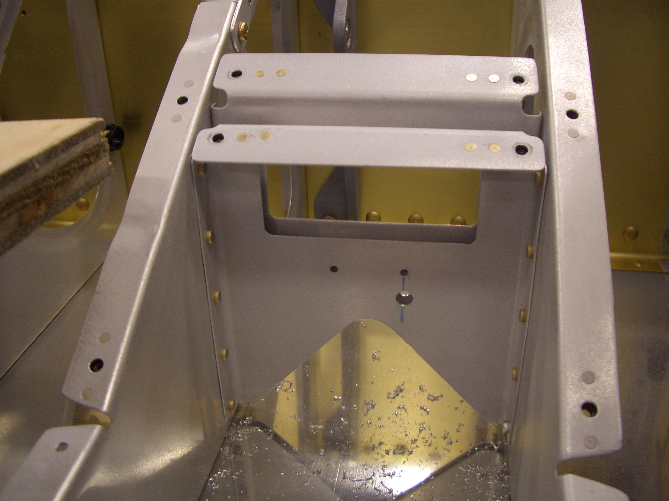
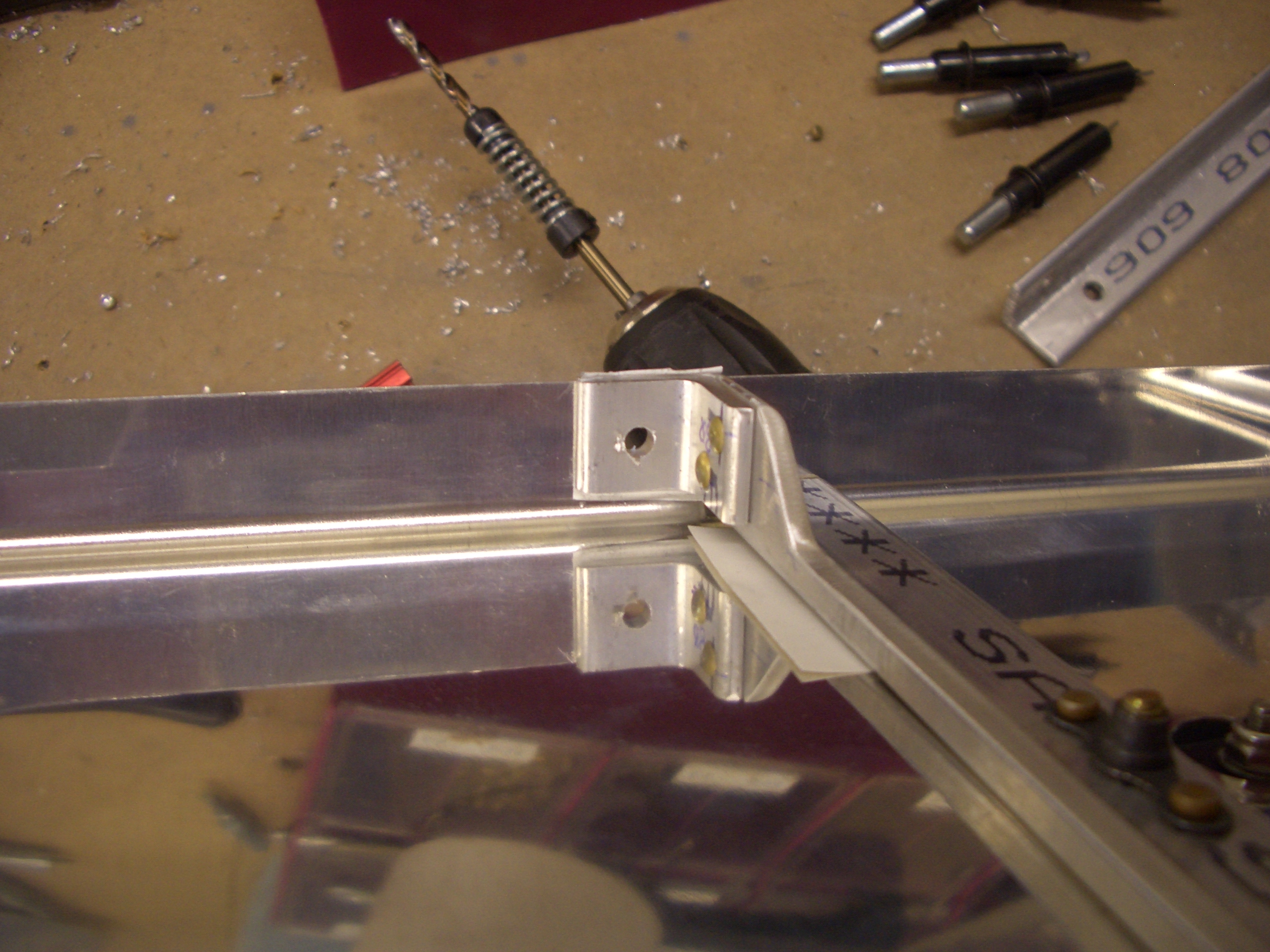
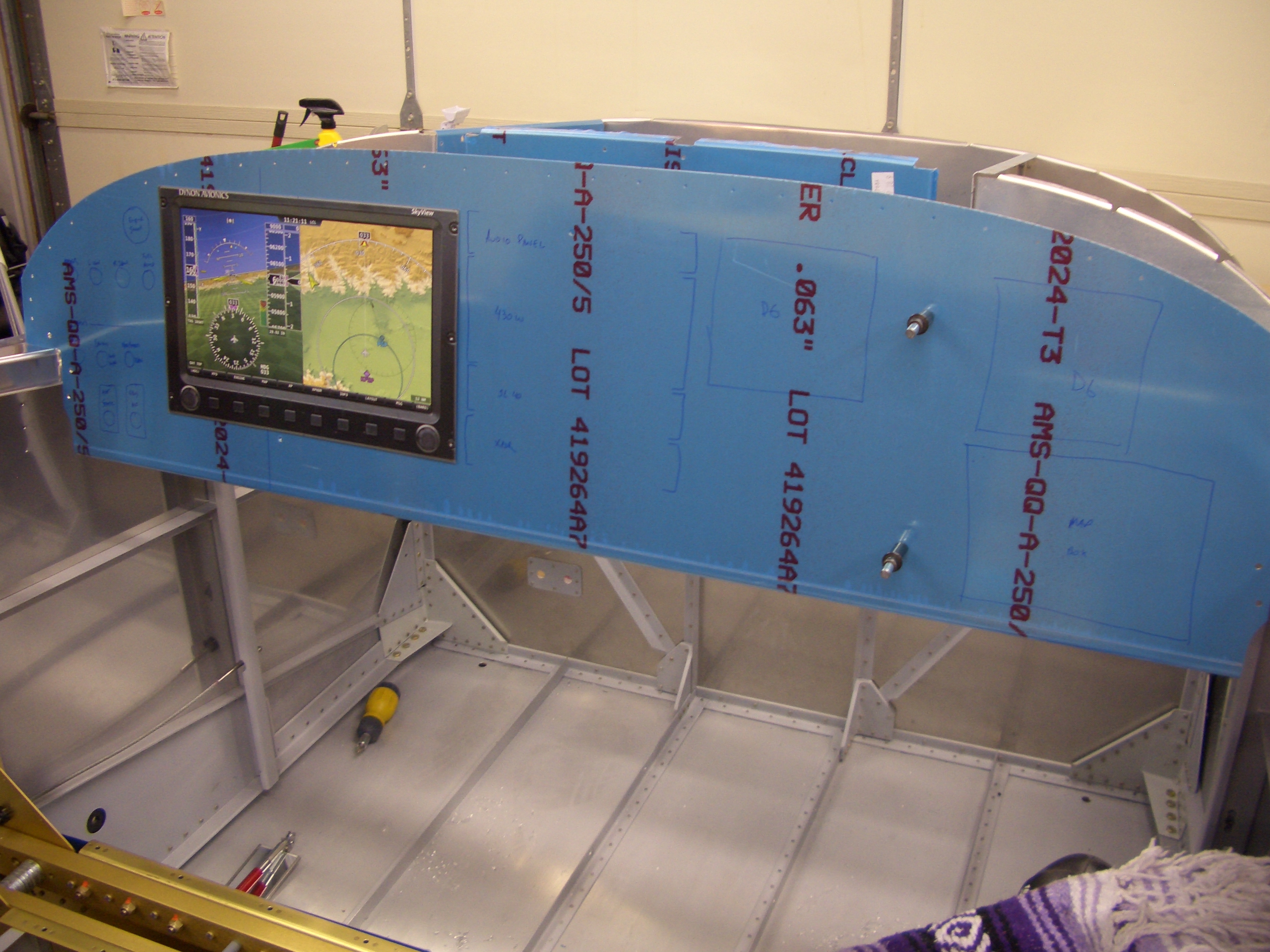
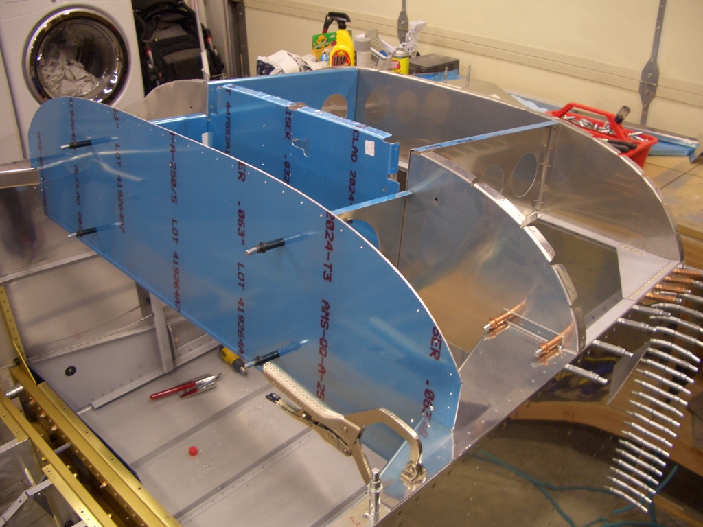
Next, I clecoed the upper forward fuselage structure together.  The left most panel is the instrument panel.  The middle panel is the subpanel, and the firewall is on the right.  There are two large ribs that tie these pieces together as well as a couple of large gusset plates that tie the longerons to the subpanel.

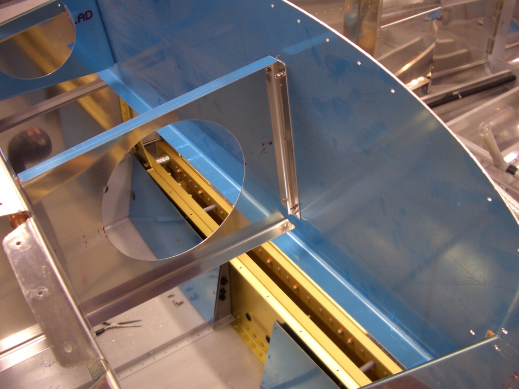
Here is the back side of the instrument panel showing how the rib supports the panel.  Unfortunately, part of this rib will have to be cut away to make room for the SkyView display.

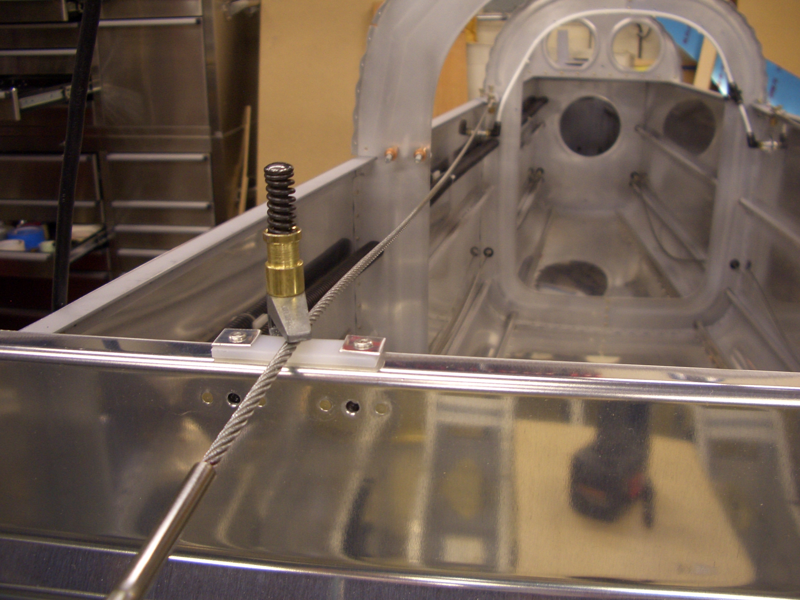
I have been playing with instrument panel layouts in ePanelBuilder, but I was unsure where the centerline of the seat is relative to the panel.  I measured this out and made a couple of marks on the panel.  I then got in the plane and spent a little time toying with layouts.  In this picture, the SkyView display is a little over an inch to the right of the centerline of the pilot’s seat, but I think I like it better there rather than directly in front of me since it provides room on the left of the display for a bank of switches and makes the display easier to reach with my right hand.  There is still plenty of room to the right for the radio stack, a Dynon D6 as a backup PFD, and the map box.

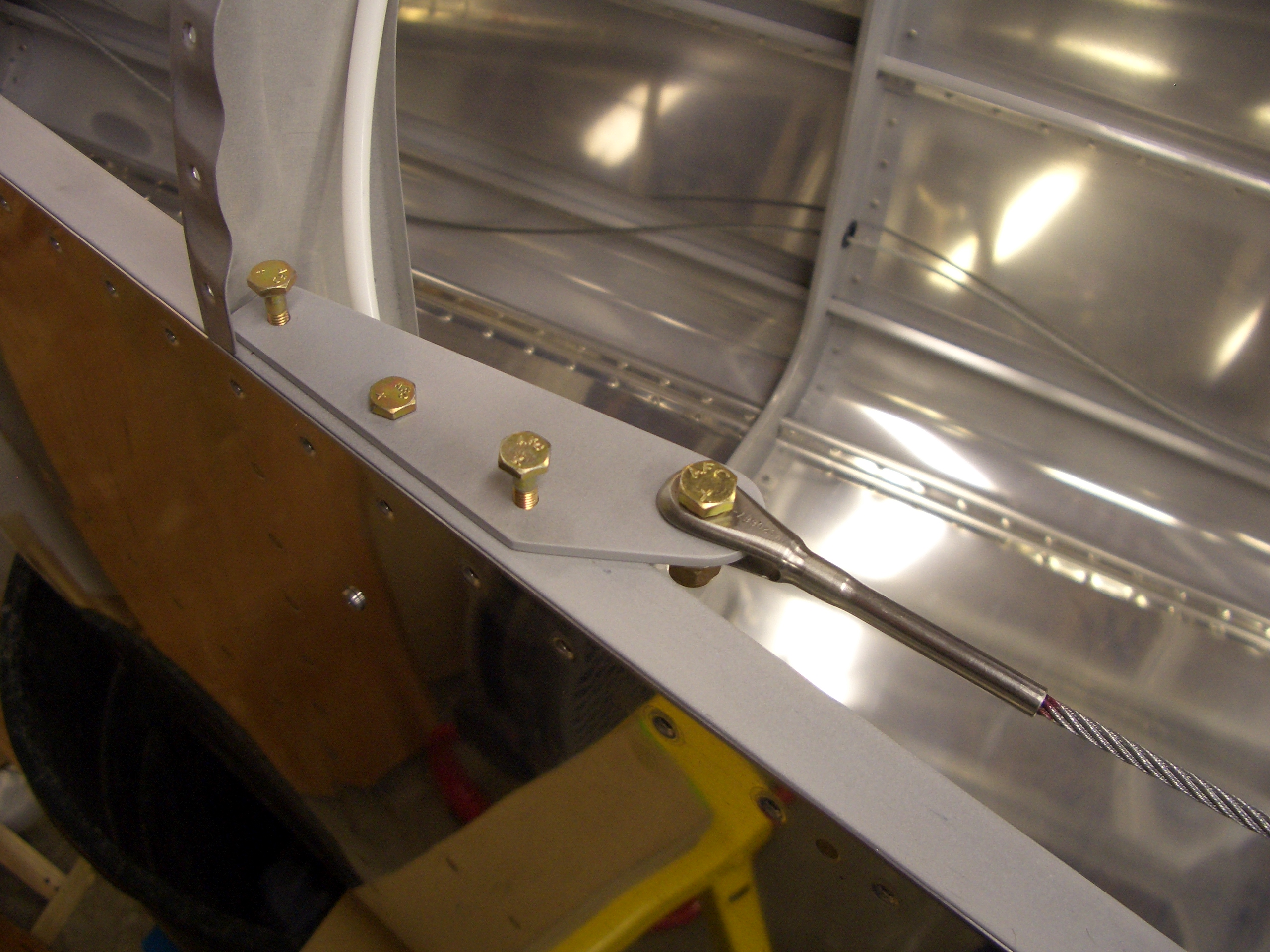
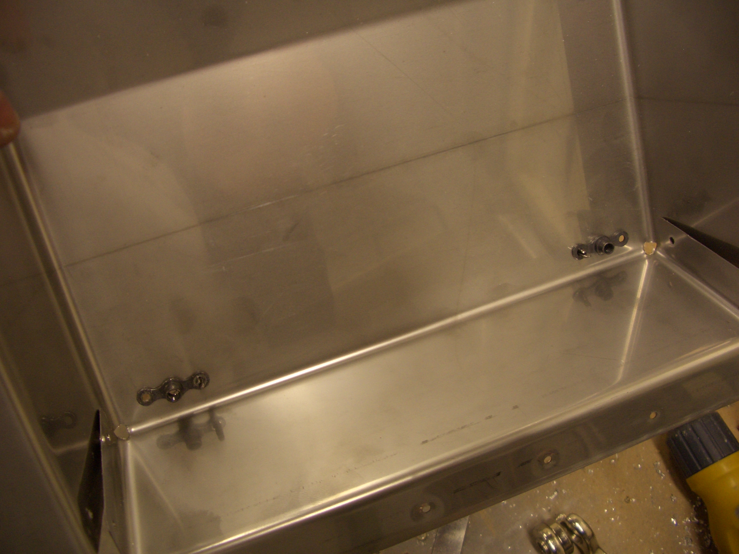
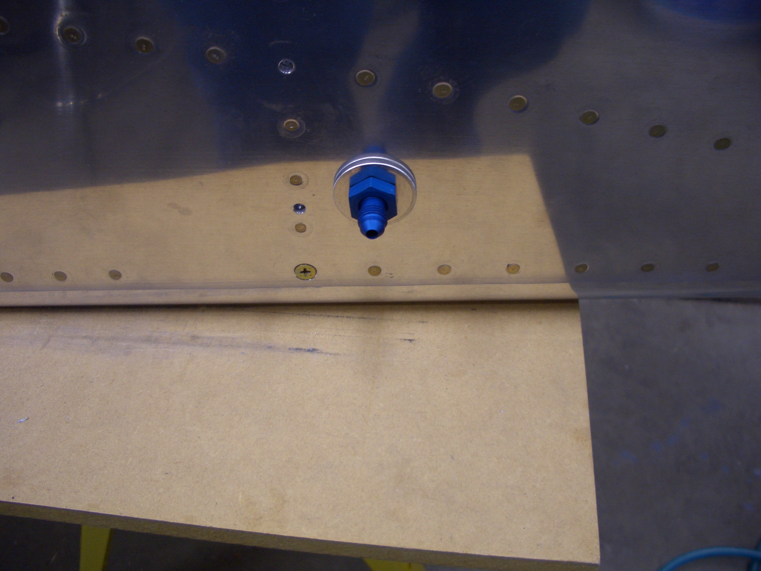
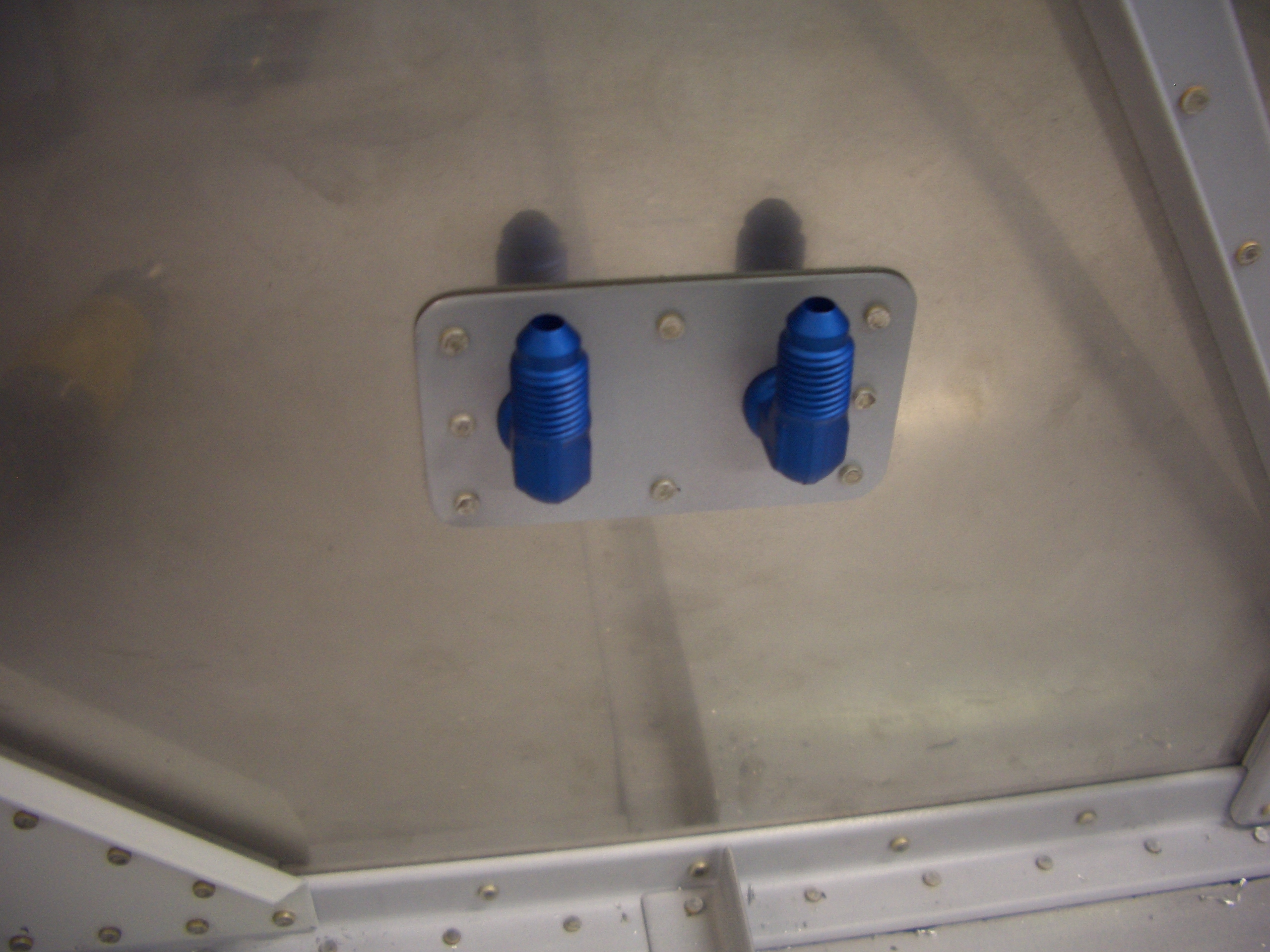
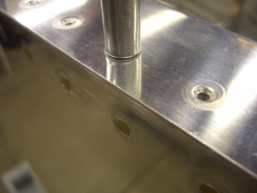
I have no idea why I decided to do this tonight, but I installed the fittings for the fuel tank vent lines into the side of the fuselage and torqued them down.  Here is the outside where the line from the fuel tank will attach.

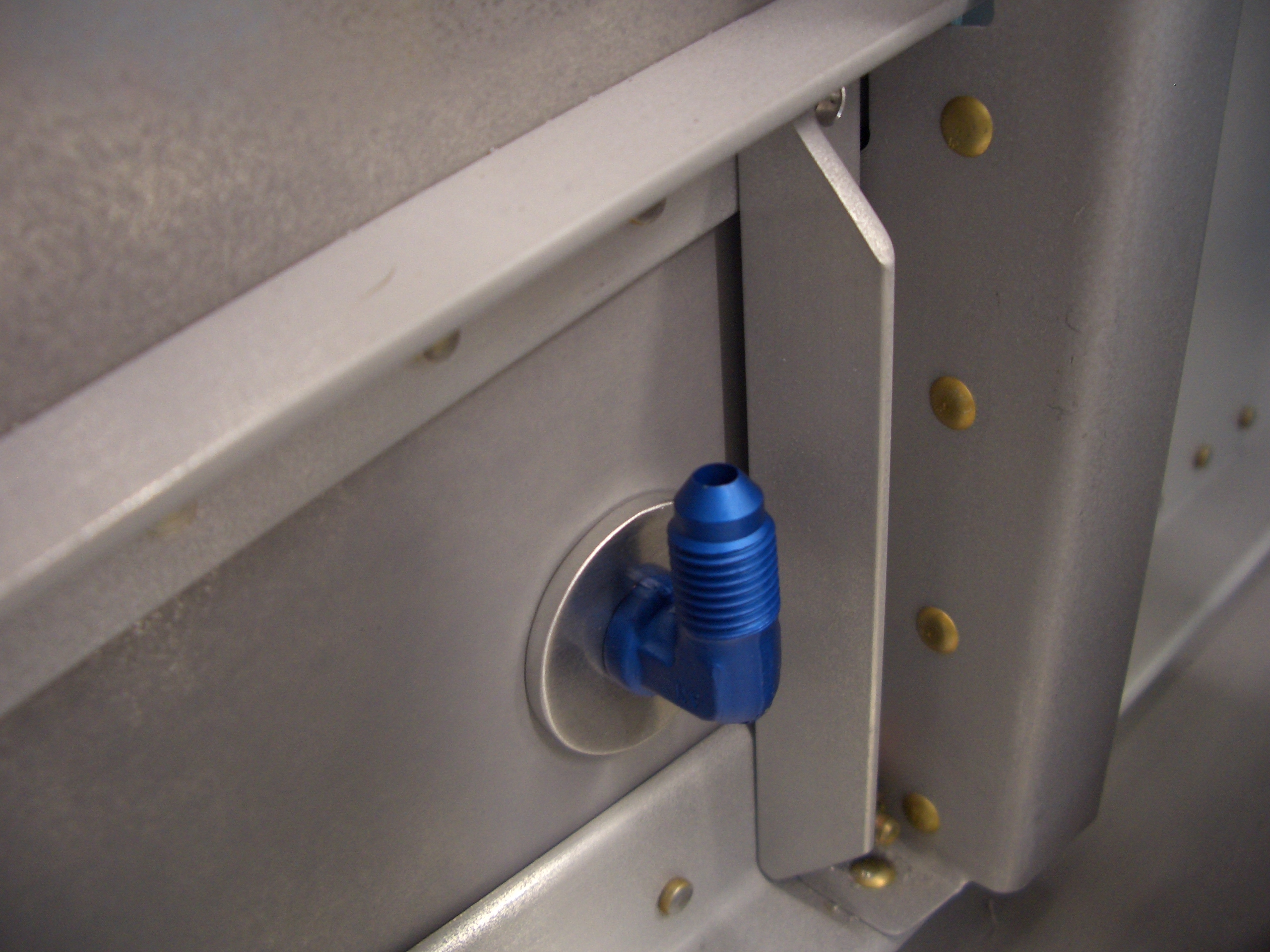
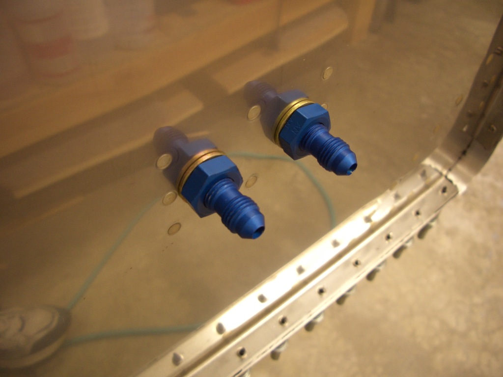
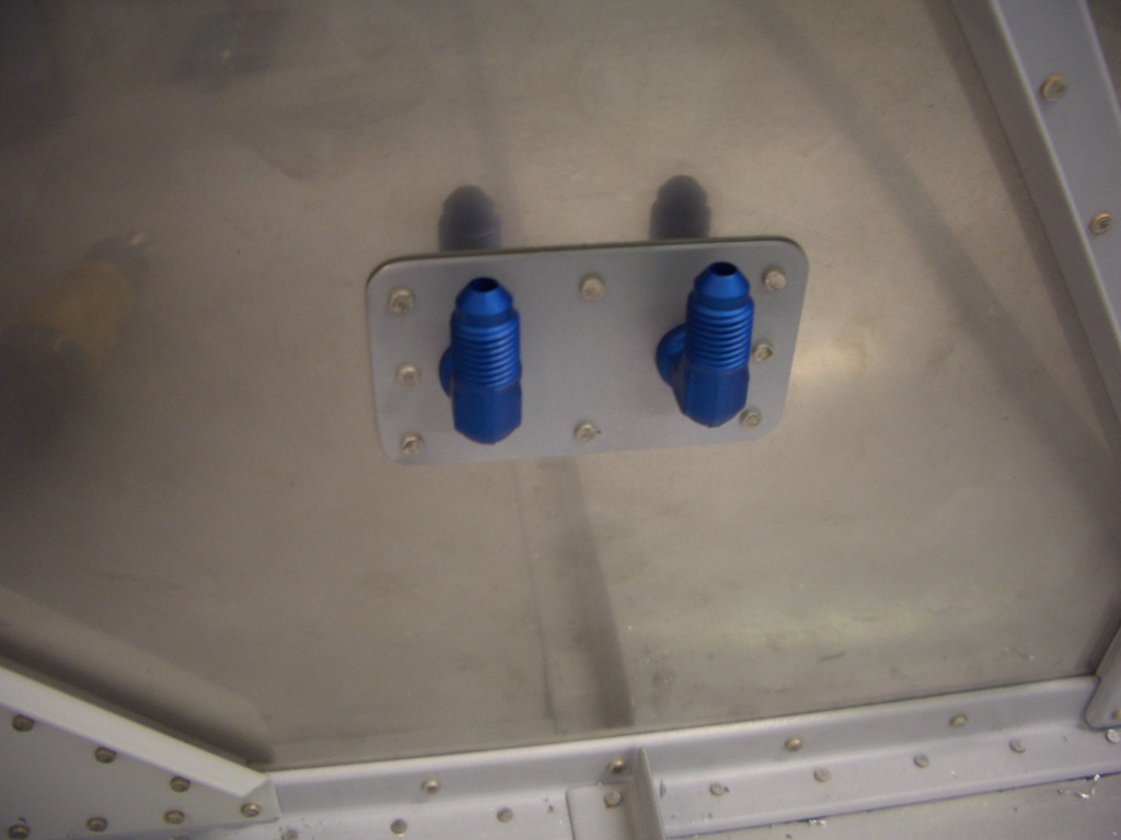
And here is the inside.  A line will attach here and run up to the upper longeron, forward to the firewall and then back down to a fitting in the floor.

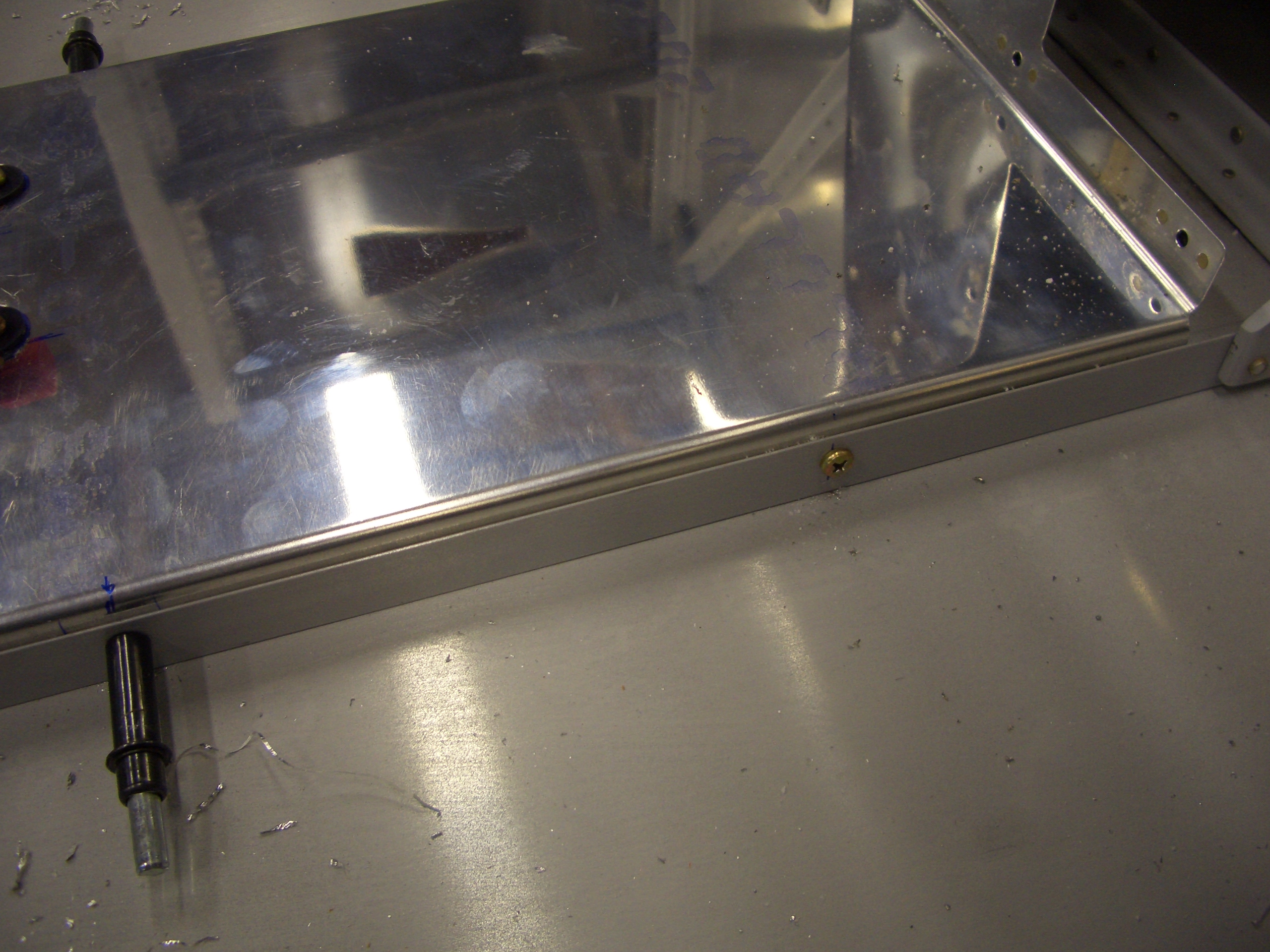
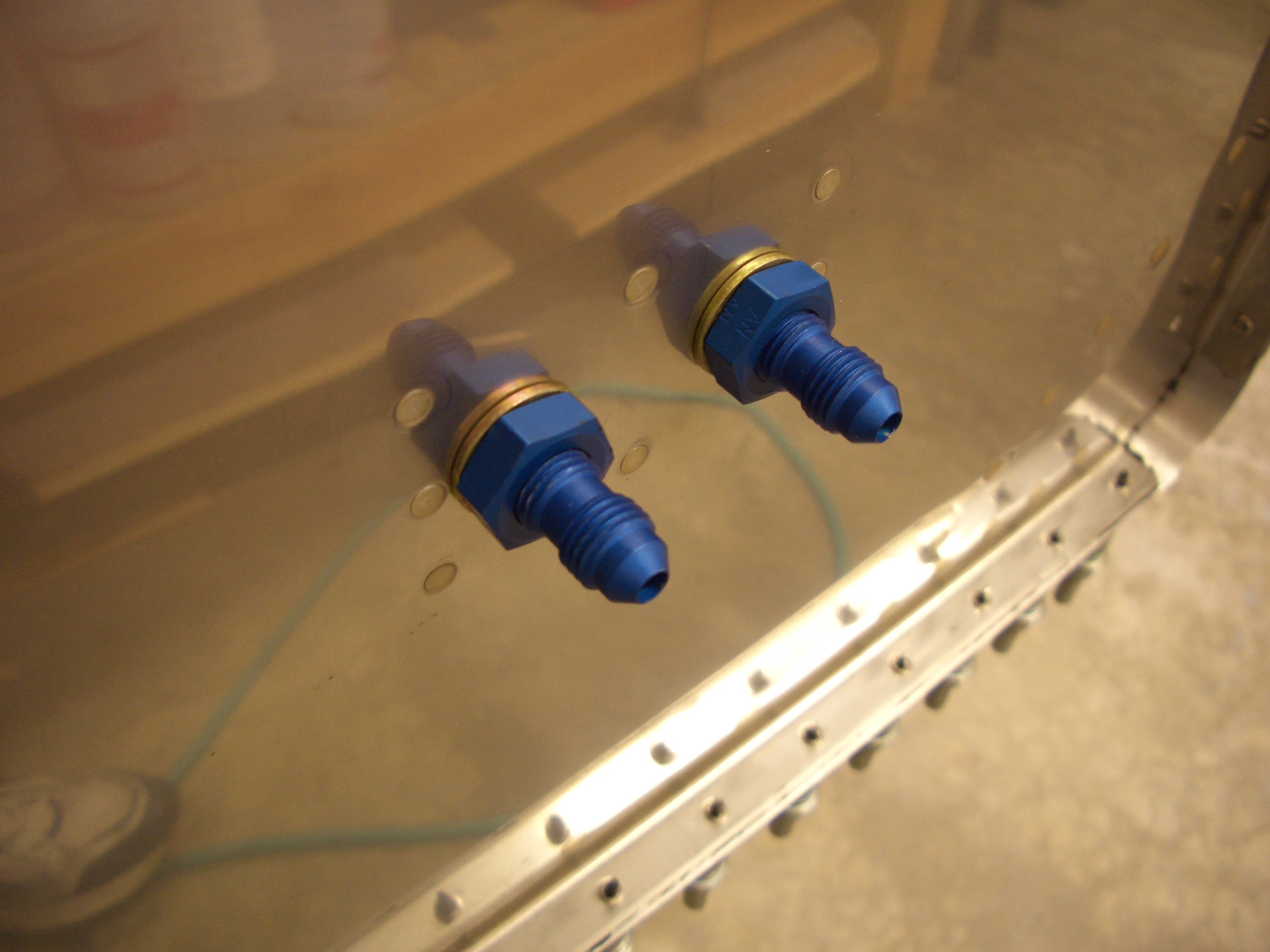
I also installed a couple of the same fittings through the firewall for the brake lines.  Here is the forward side of the firewall.  Lines will attach here and then run down the gear legs to the wheels.

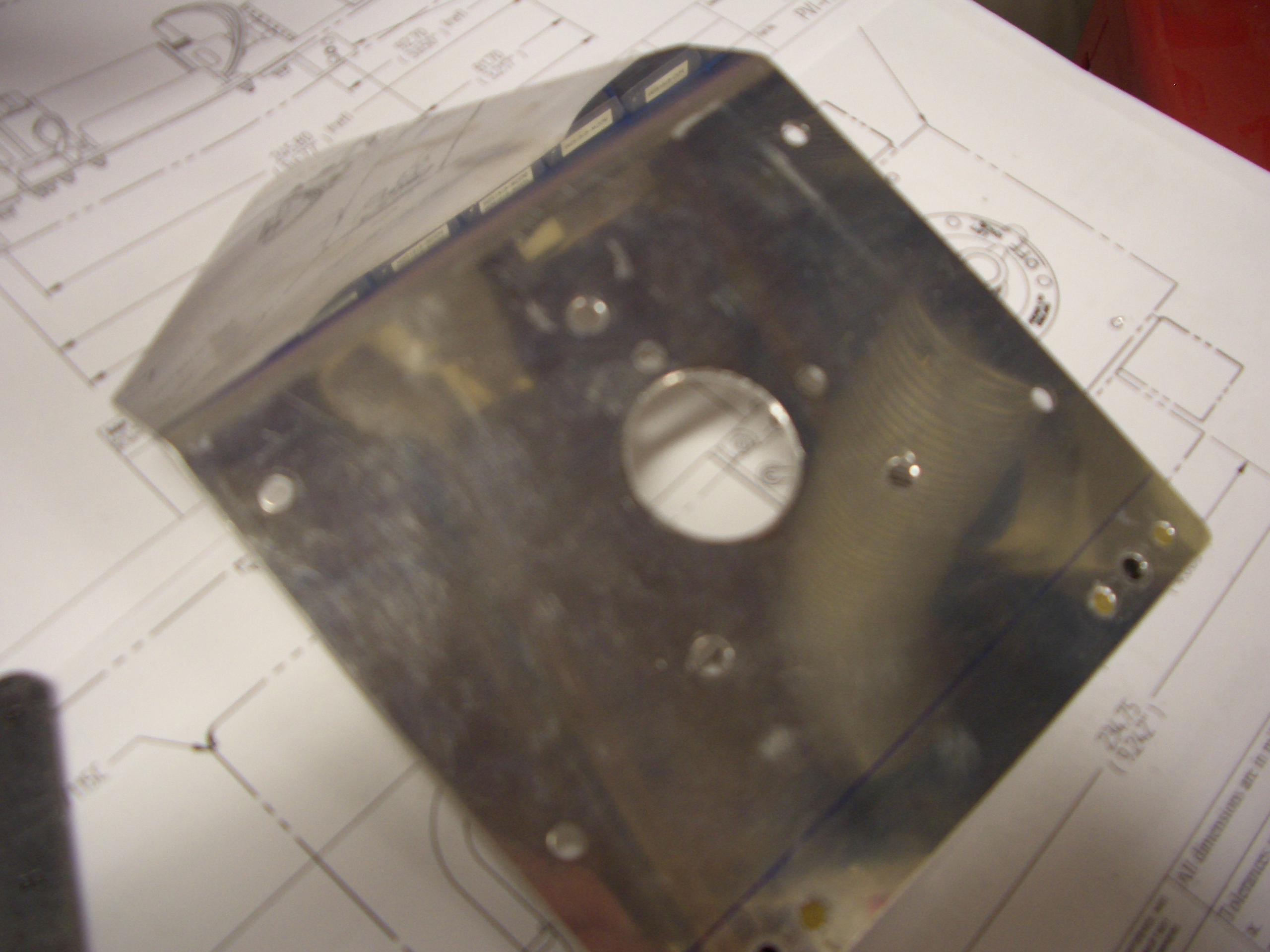
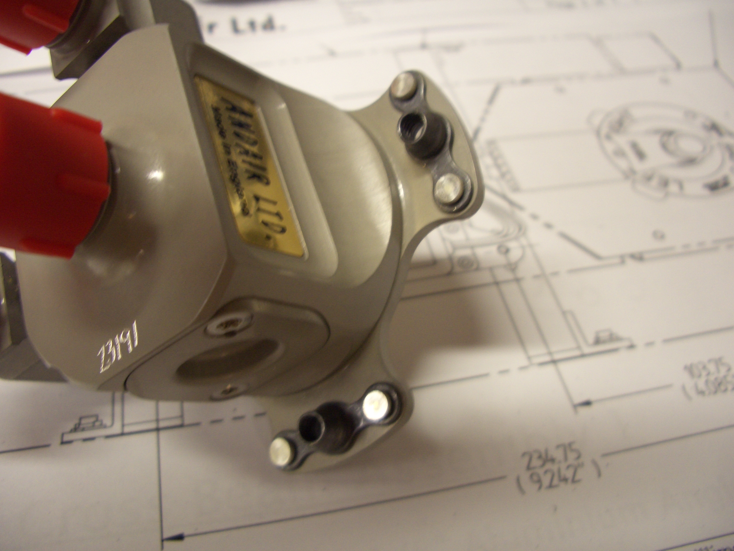
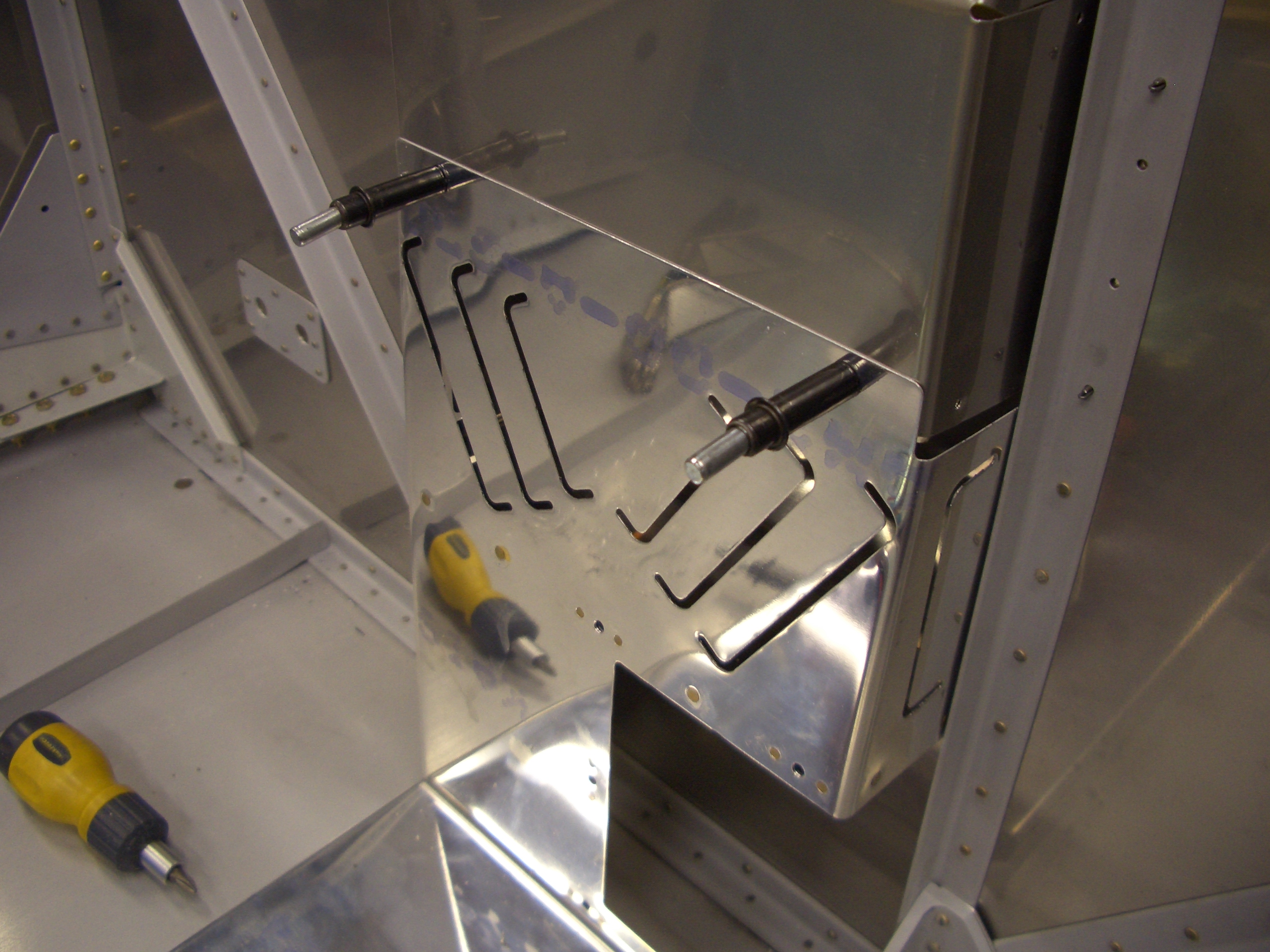
Here is the aft side of the firewall.  These fittings face upward since the parking brake valve will be mounted above this point.

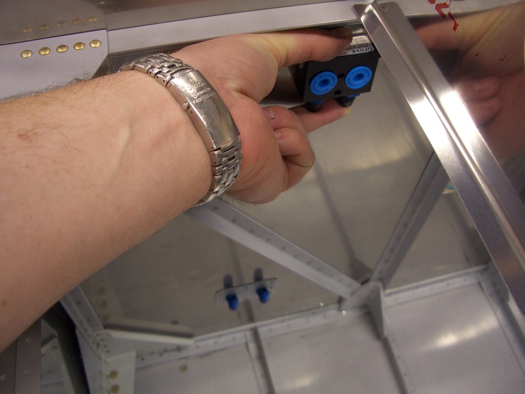
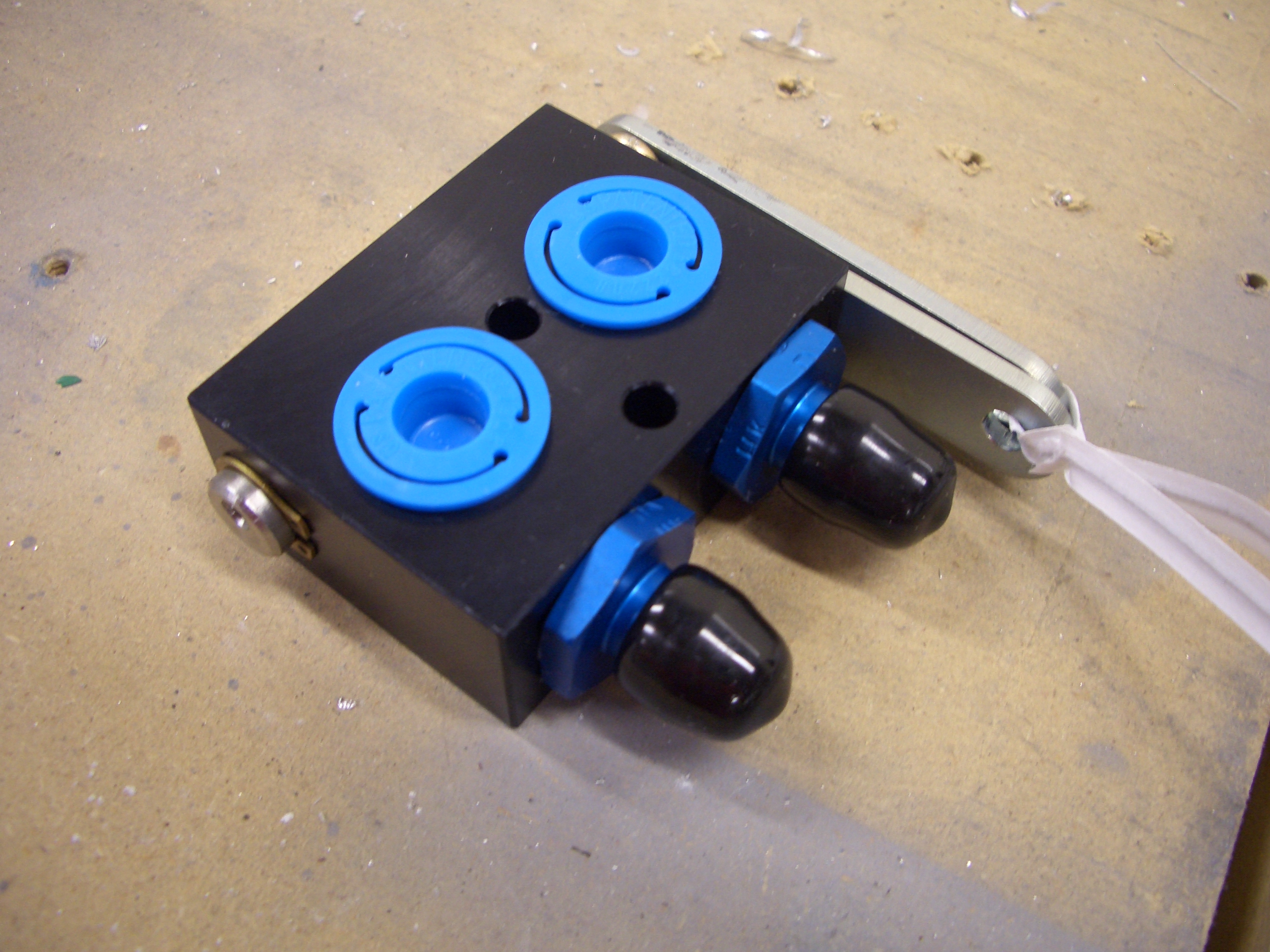
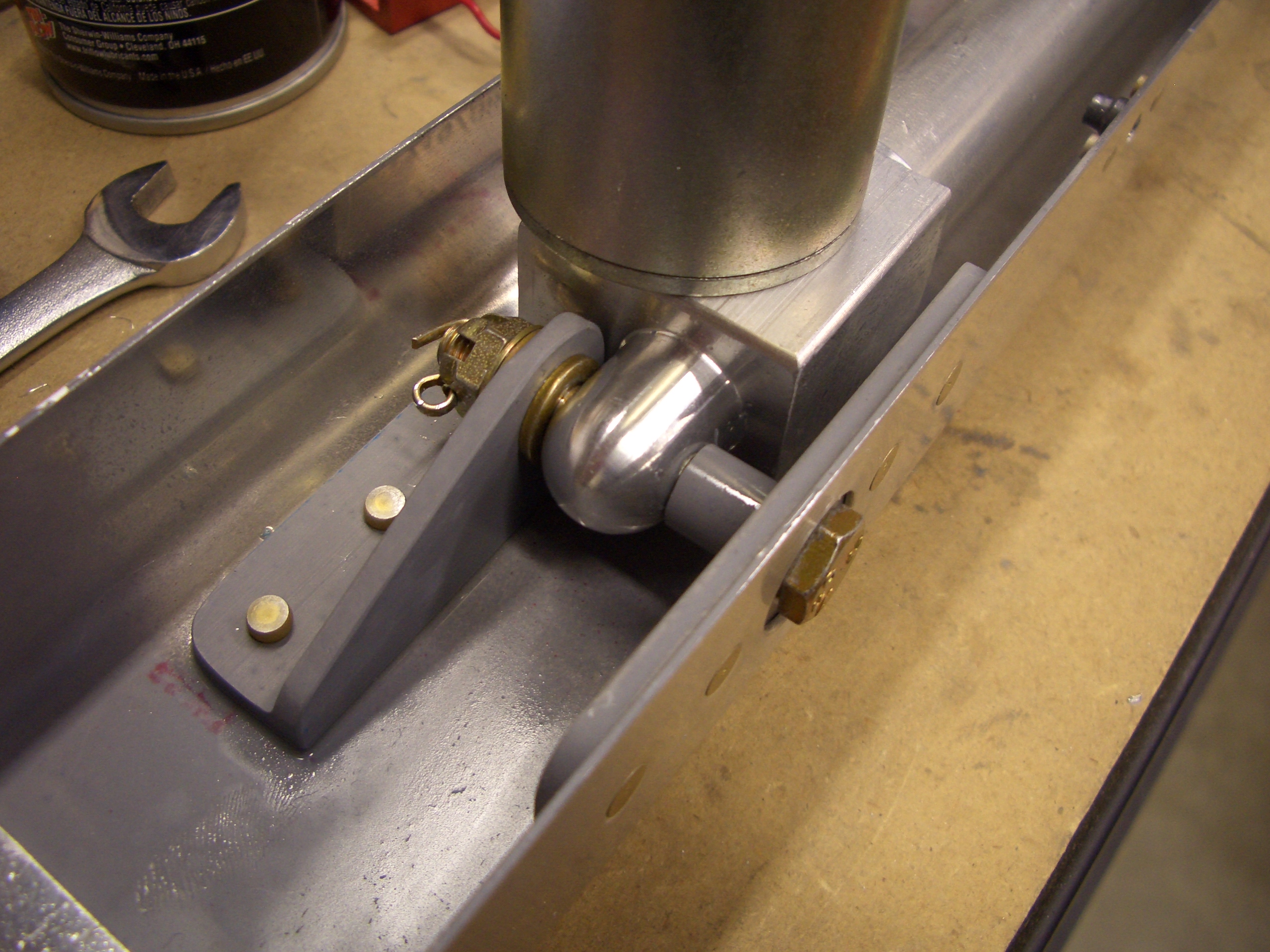
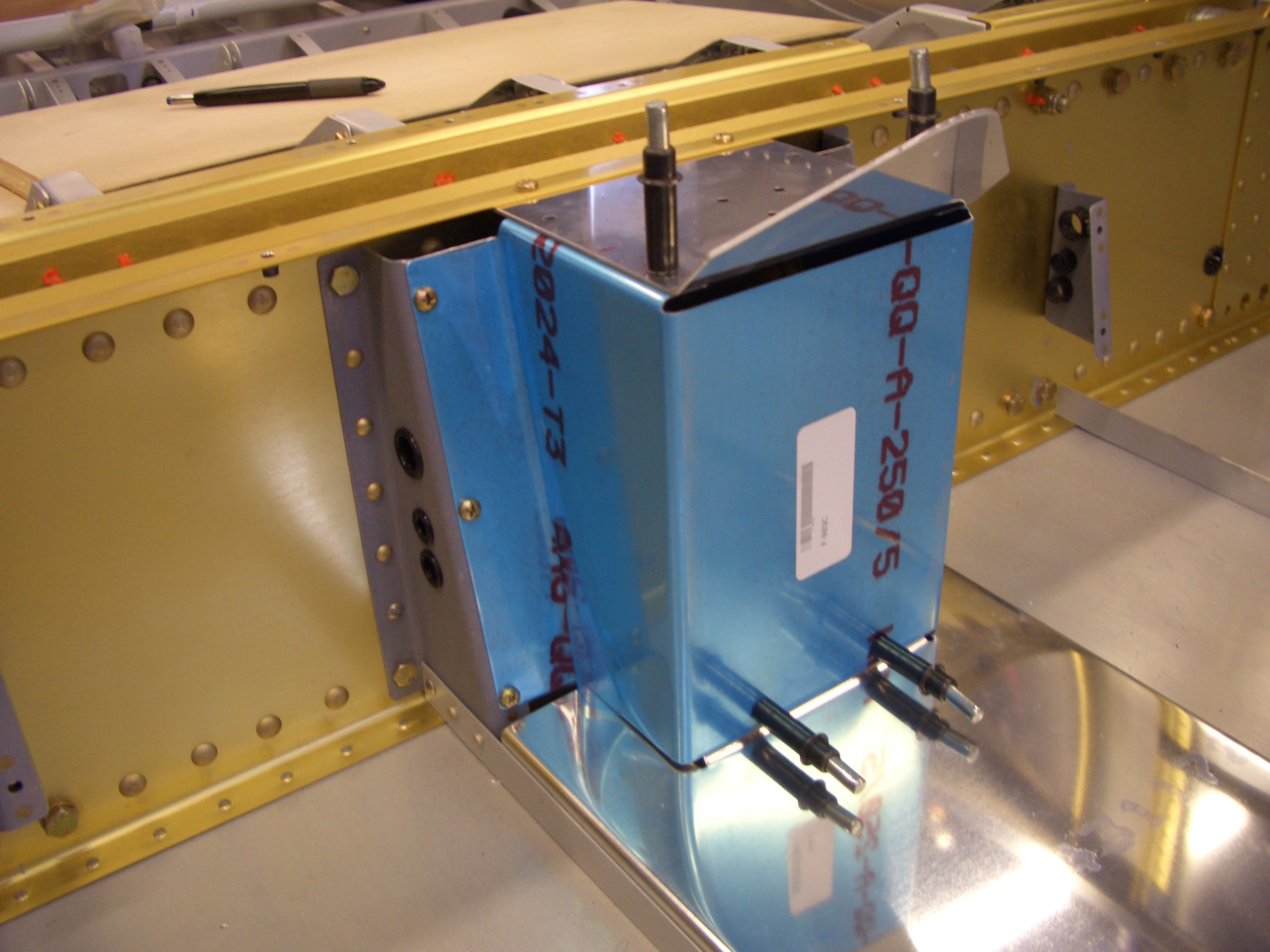
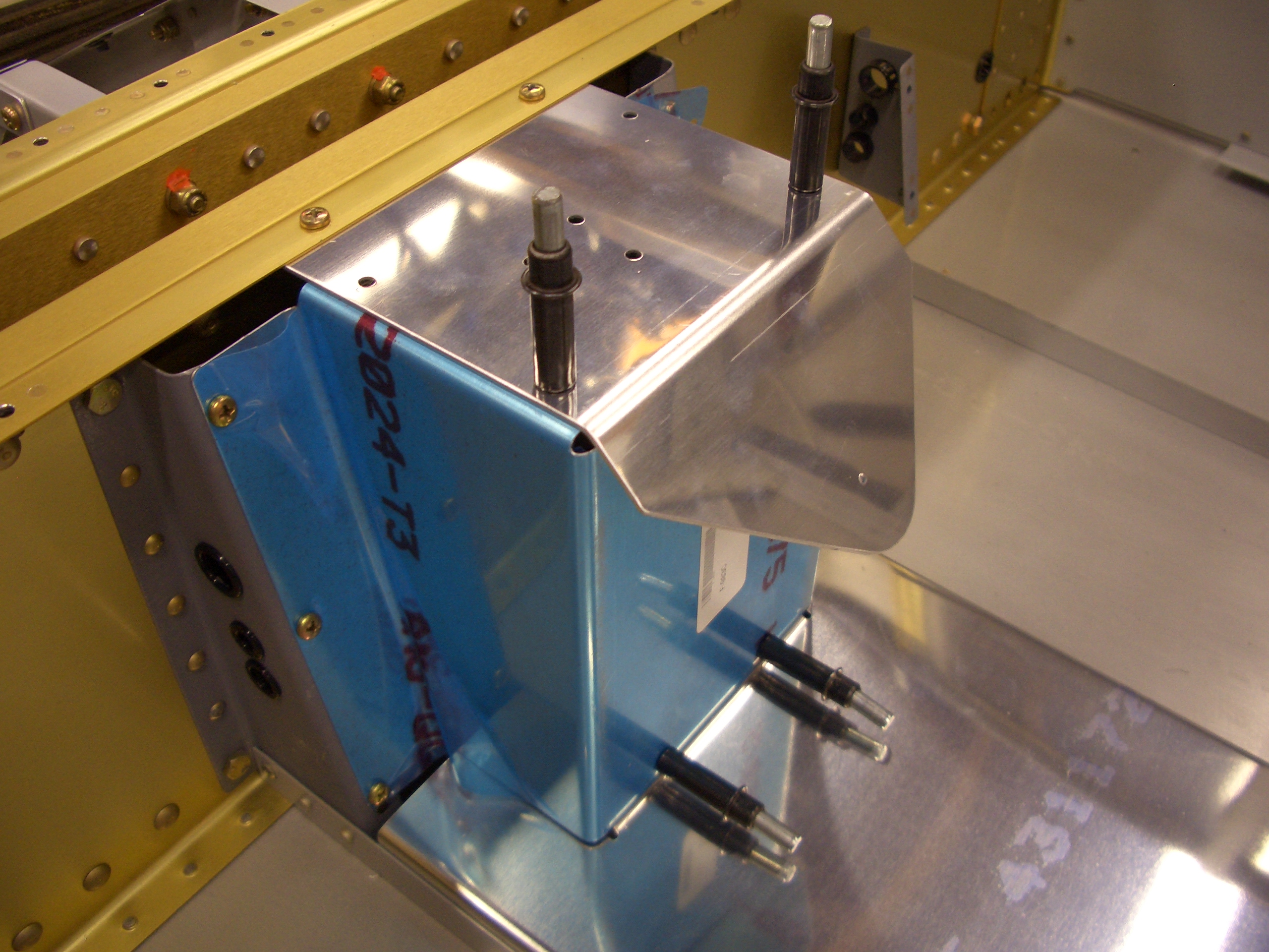
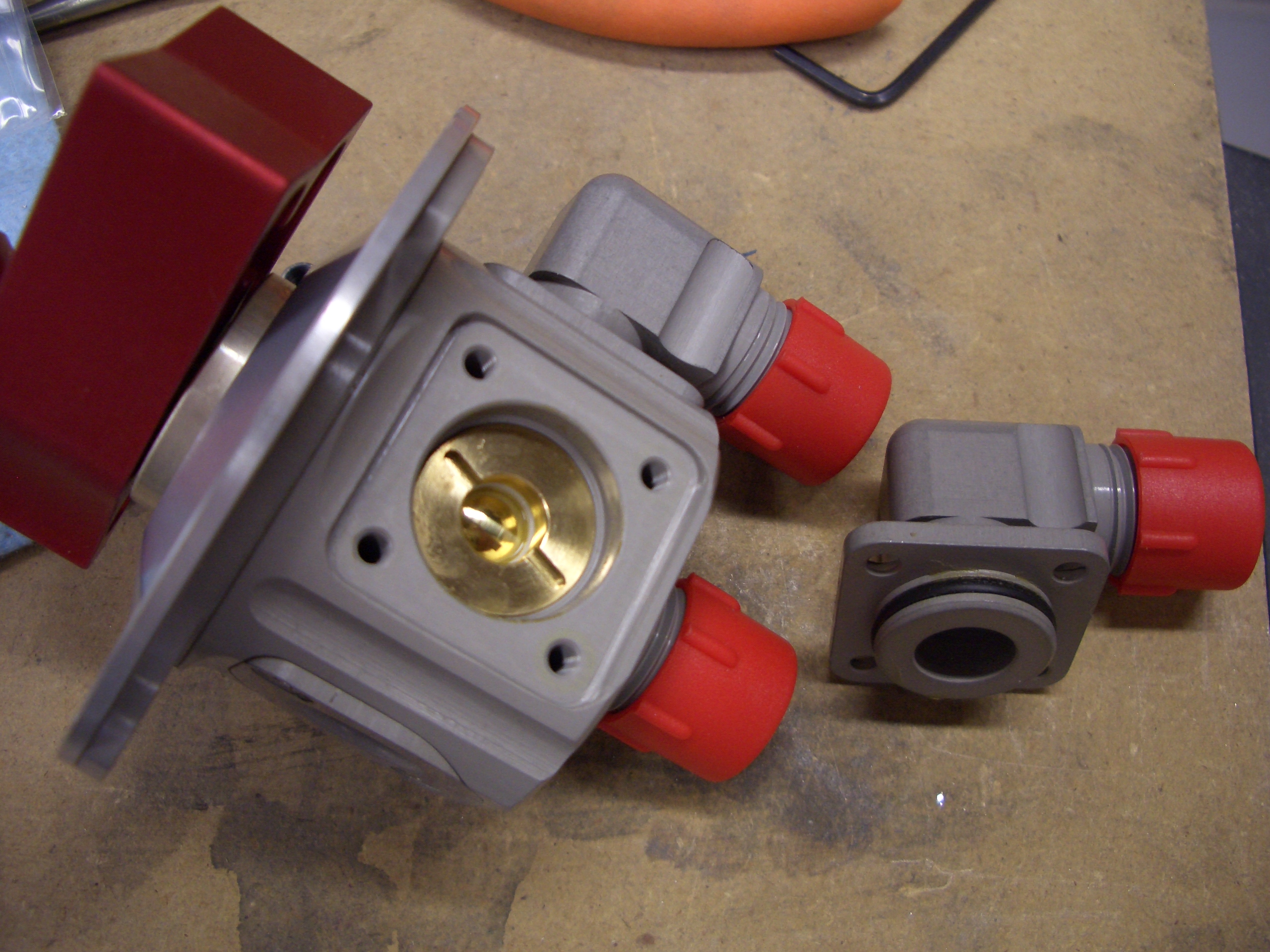
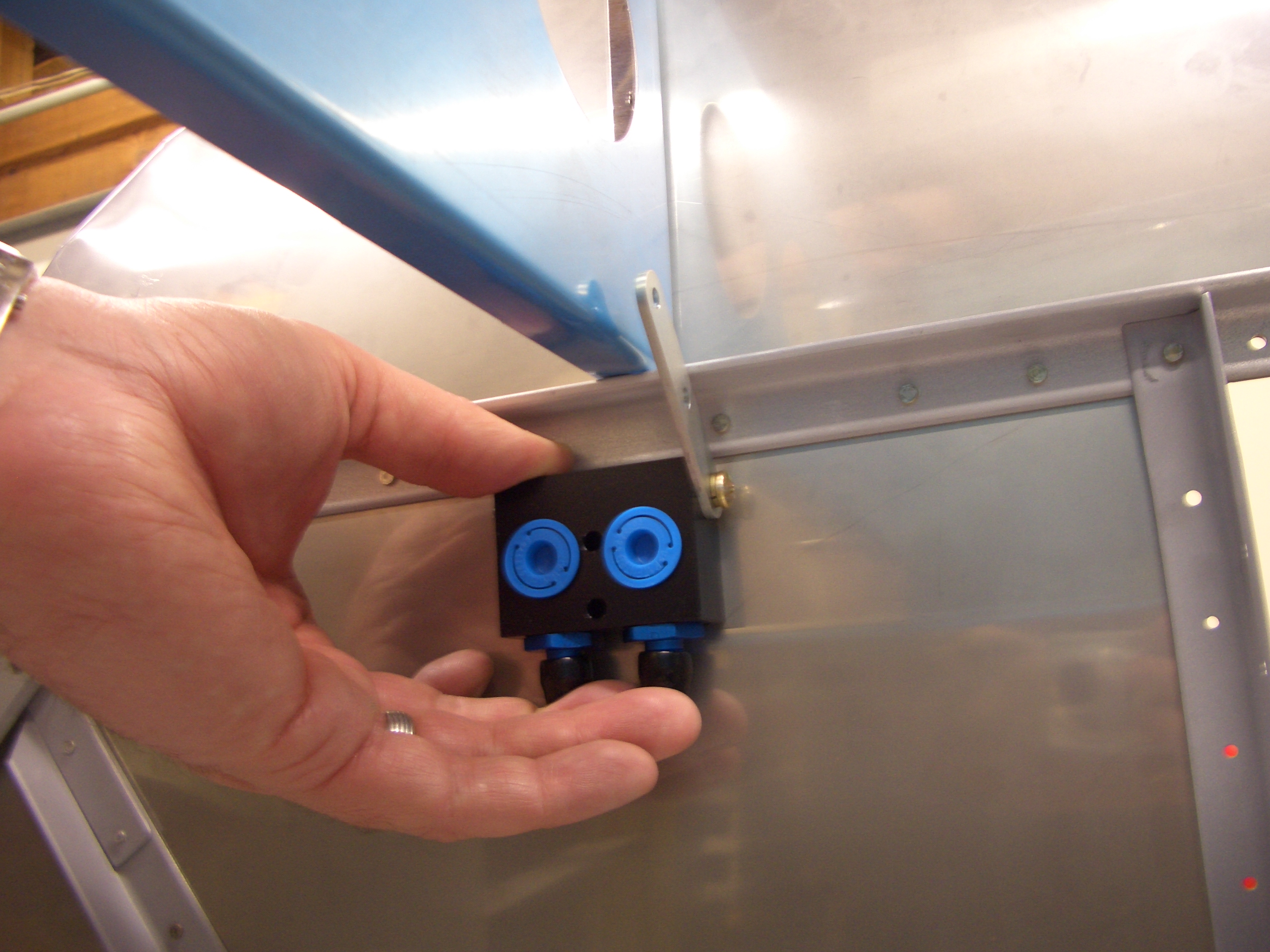
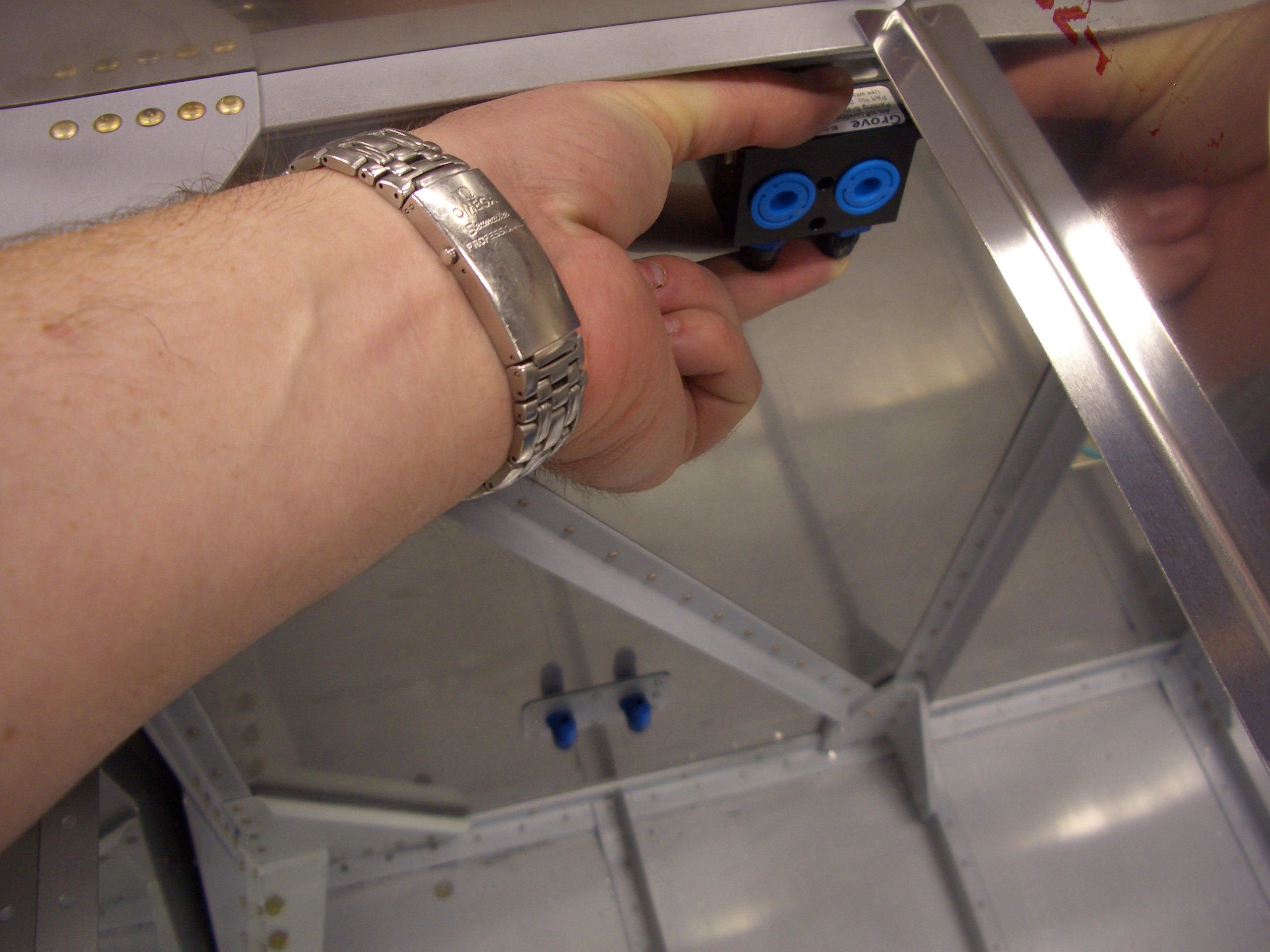
Here is roughly where I’m planning on mounting the parking brake valve.  This gives me a convenient point on the rib above to attach the parking brake cable.  I’m going to hold off installing this for a bit to make sure this mounting point doesn’t interfere with anything of the front of the firewall.

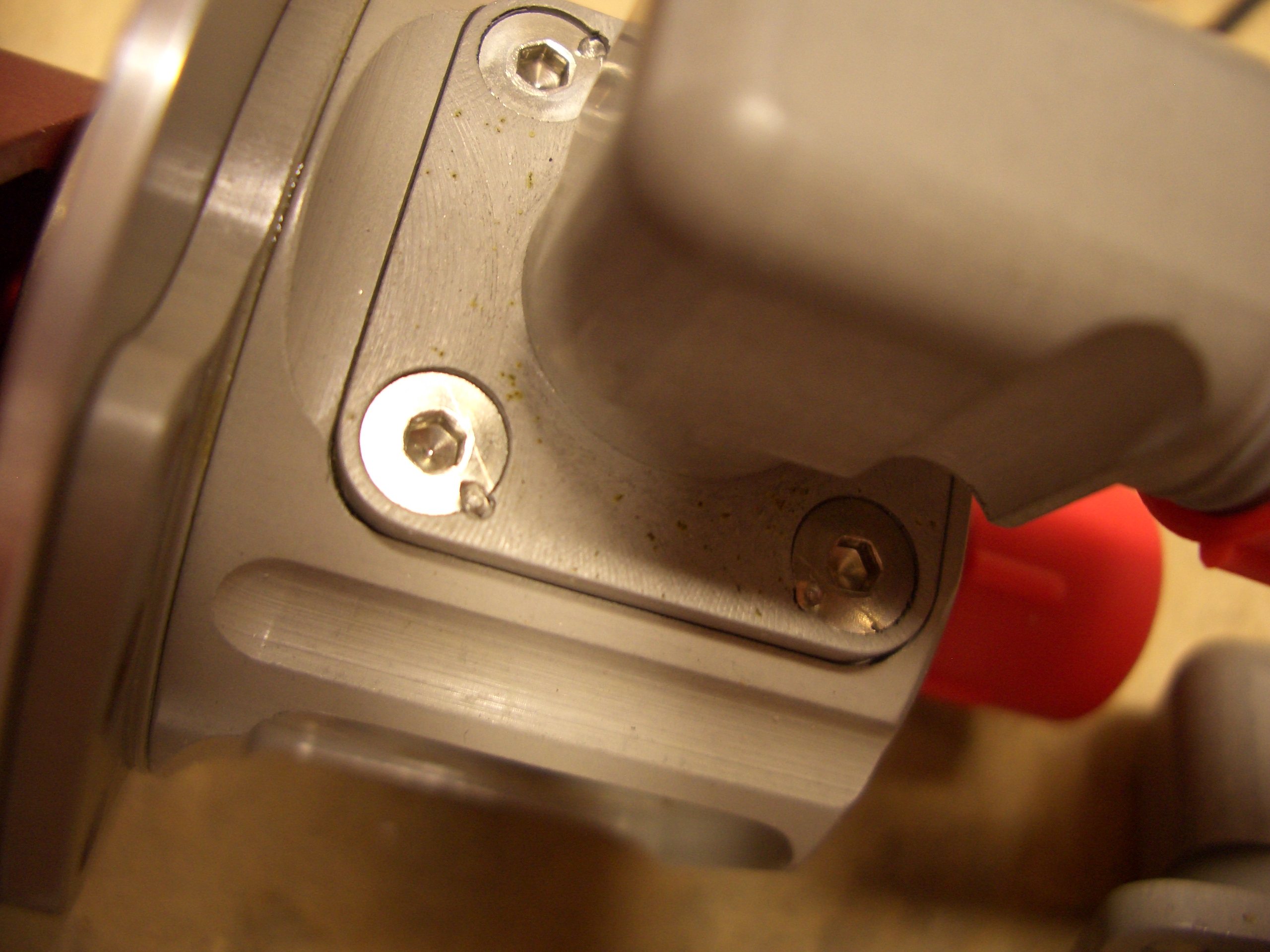
Here you can see that it’s a fairly straight shot from the parking brake to the fittings through the firewall.  I’ll fabricate solid aluminum lines to connect these two.

Forward Fuselage Fabrication and Panel Layout

I got an order from Van’s today that included the fuel pump cover.  This normally sits higher than this because the forward face of this is vertical and the angled face is more steeply sloped upward.  This provides room for the much larger Airflow Performance fuel pump/filter/check valve assembly.  This configuration won’t work for me because I had to move the fuel pump forward almost 2″ to fit the fuel line between the fuel selector and the fuel filter.  This puts the pump outlet far enough forward that there is no room to allow the fuel line on the outlet side room to turn down and drop under the cover.

I reduced the angle of the bends in the cover, which simultaneously drops the height of the cover down as well as pushes the front end forward enough to make room for the fuel line..  I’ll have to fabricate new side covers from some scrap 0.020″ stock, but that’s pretty trivial.

I started fabricating some of the small components for the forward fuselage out of 0.063″ angle stock, but it’s late and this was making a racket.

Instead, I spent a little more time playing with panel layouts in the plane.  The cockpit is small enough that I can reach every part of the instrument panel from the pilots seat without leaning over (I have really long arms though).  This also means that it’s pretty easy to see everything, regardless of where it is on the panel.  I’ve been planning on going with a single 10″ screen Dynon SkyView system, but lately I’ve been considering trying to fit a dual 10″ screen into the panel.  Even with the 10″ screen, using just one screen for PFD, Map, and engine monitoring can get kind of cramped.  I think dual screens would force me to remove the Dynon D6 that I was planning to use as a backup PFD though.  Although I could add a second ADAHRS box, I’d still be relying on a single overall system which worries me a little bit.

Fabricated Instrument Panel Stiffener

The instrument panel has a stiffener that runs along the back side of the top edge.  It’s a piece of 0.063″ angle that’s notched so that it can be bent to follow the curve of the top edge of the panel.  I noticed after taking this picture that the wide flanges near the ends need to be cut off to better help this follow the curve of the panel.  I’ll have to take care of the tomorrow.

Here is a closeup showing the notches and how this allows the stiffener to be bent.

I cut the notches on the band saw and then started filing them smooth.  I was really regretting not buying an air file the last time I was at Harbor Freight, but then I got the bright idea of trying one of my needle files in my jigsaw.  This worked beautifully, and I was able to smooth out the rest of the notches in just a few minutes.