Installed Aft Baggage Side Walls

After vacuuming out all of the metal shavings in the fuselage aft of F-705, I installed the side walls.  These use LP4-3 rivets along the top an AN426AD4-4 rivets along the back.  After I finish modifying the baggage floors for the hatches, they will rivet to the ribs and the lower flange of this panel.

Match Drilled AHRS Mount Kit

I ordered the AHRS mounting kit from Van’s.  This is designed for the Grand Rapids EFIS or the Garmin G900X, but I’m going to adapt it for the Dynon Skyview ADAHRS.  I drilled out two rivets that tied the bottom skins to F-706 and F-707.  These will now additionally tie the rib pictured here.  I then ensured the ribs were parallel and match drilled the skin to the rib.  I then used the digital level to ensure the mounting plate was level laterally and match drilled it to the F-729A rib and F-707 bulkhead.  The mounting plate is tipped aft about 0.5º from the level of the longerons, but this is well within Dynon’s 1º limit.  I can always shim the ADAHRS unit if necessary.

I’m still trying to decide how to mount the ADAHRS unit to the mounting plate.  Dynon calls for nonferrous fasteners, but I haven’t been able to find stainless steel or brass nutplates.  I can reach under the front edge of the mounting plate, but I’d kind of like to install the unit near the aft end of the plate in case I want to install another unit just in front of it.

Update: I ended up not installing the ADAHRS here because it is too close to the pitch servo and this can interfere with the magnetometer.  I decided to use this to mount the ELT instead.

Primed and Riveted Fuselage Components

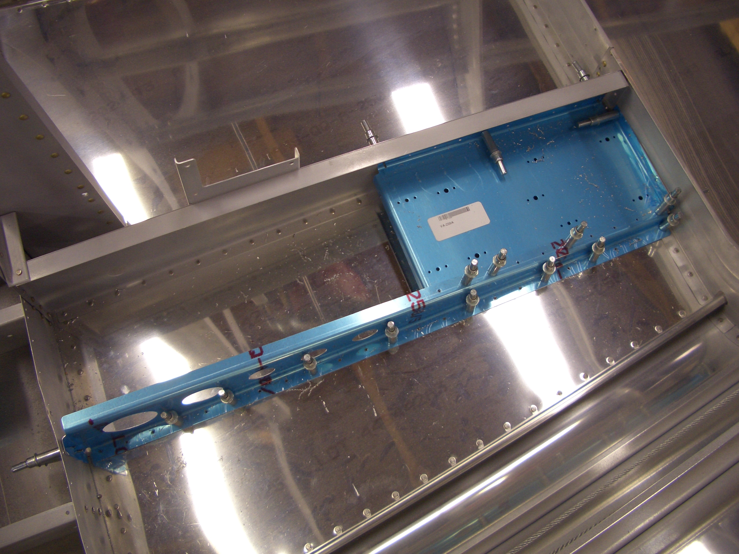
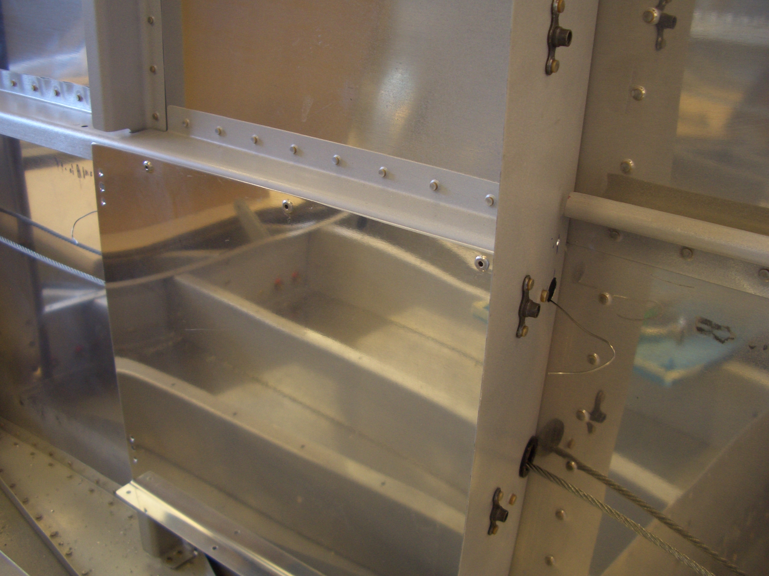
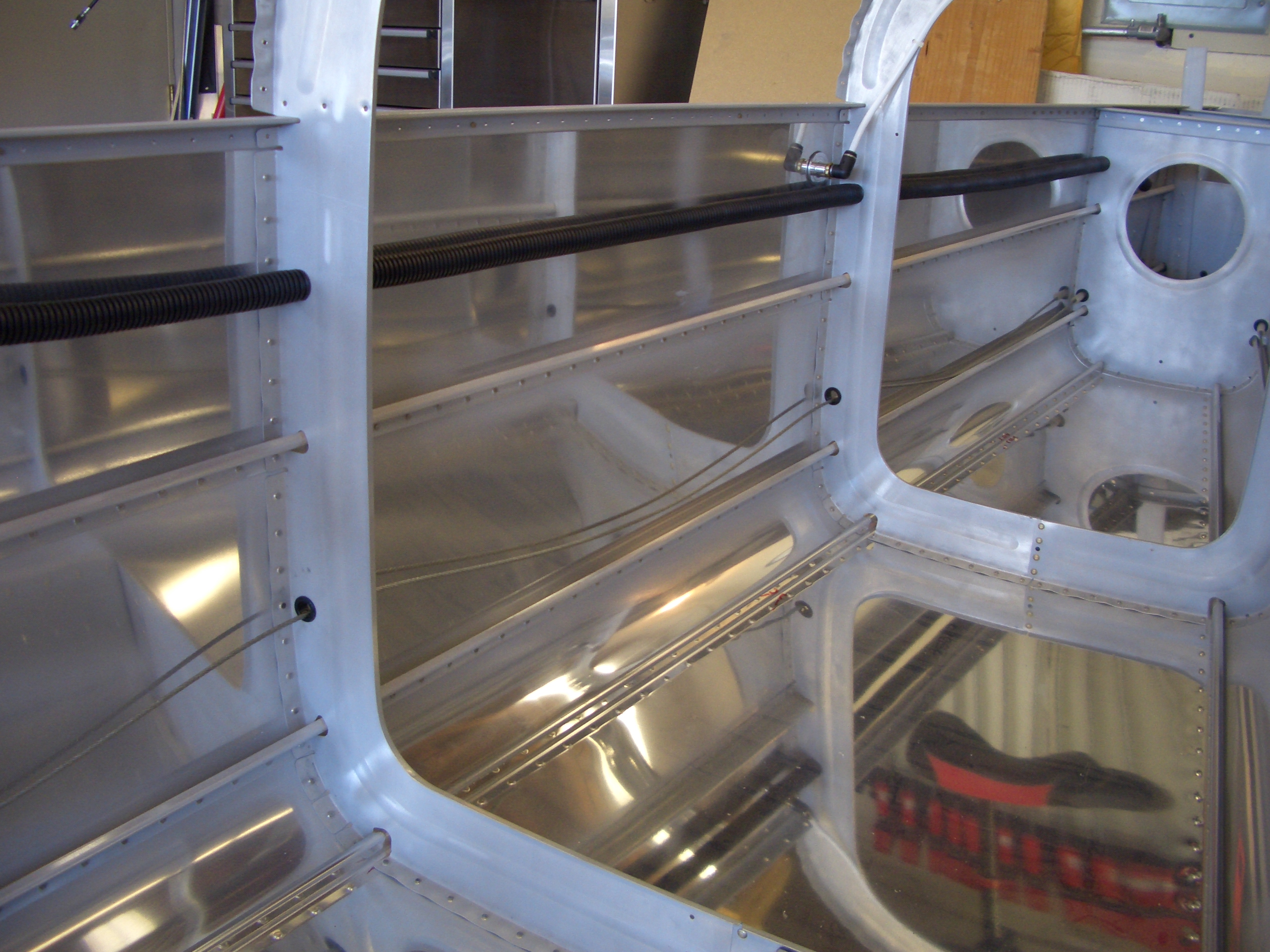
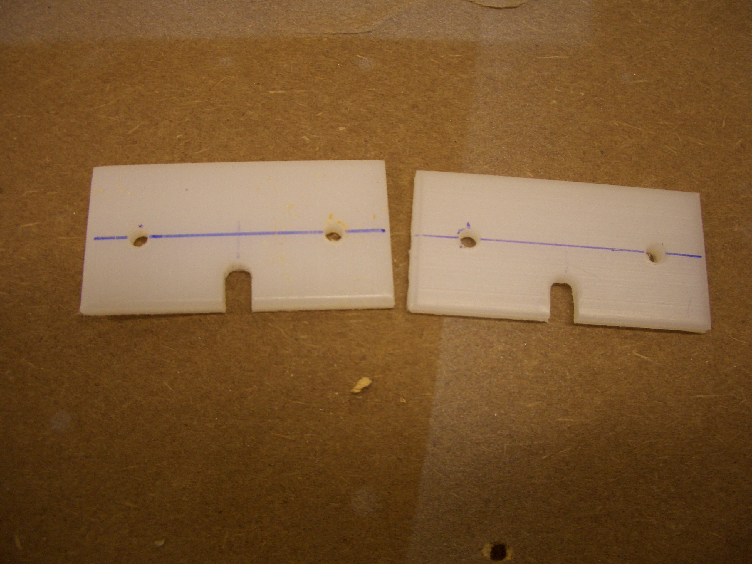
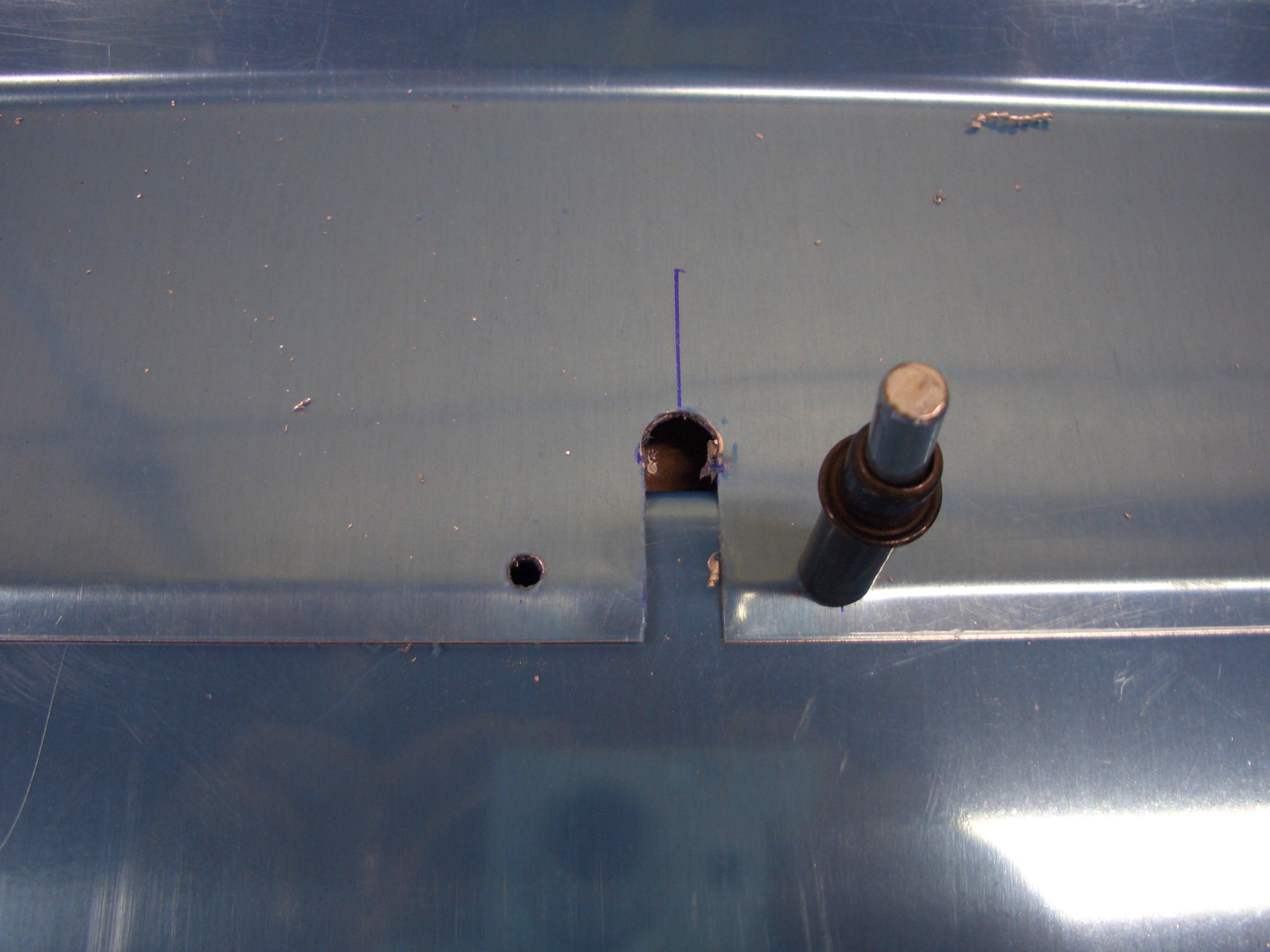
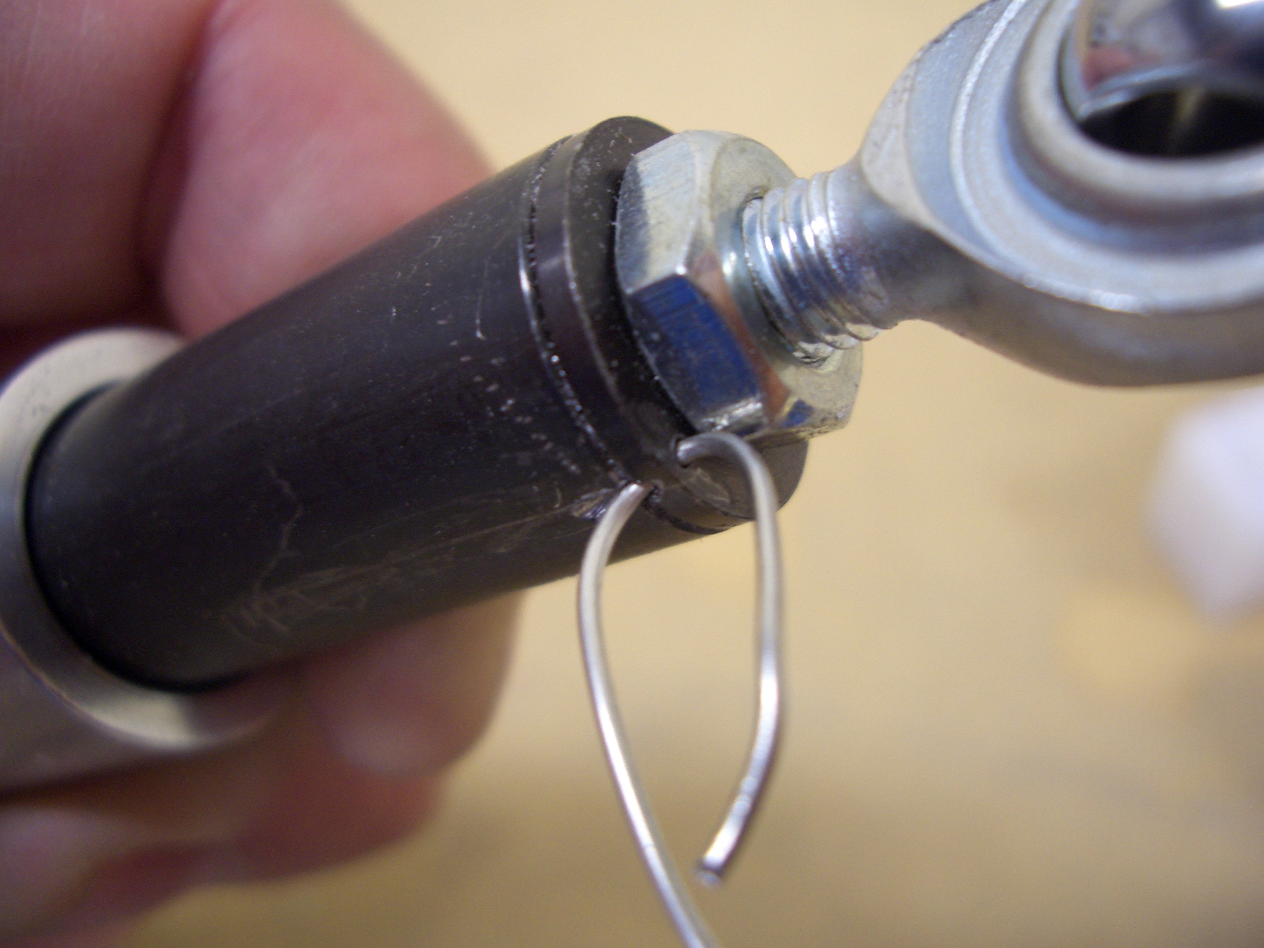
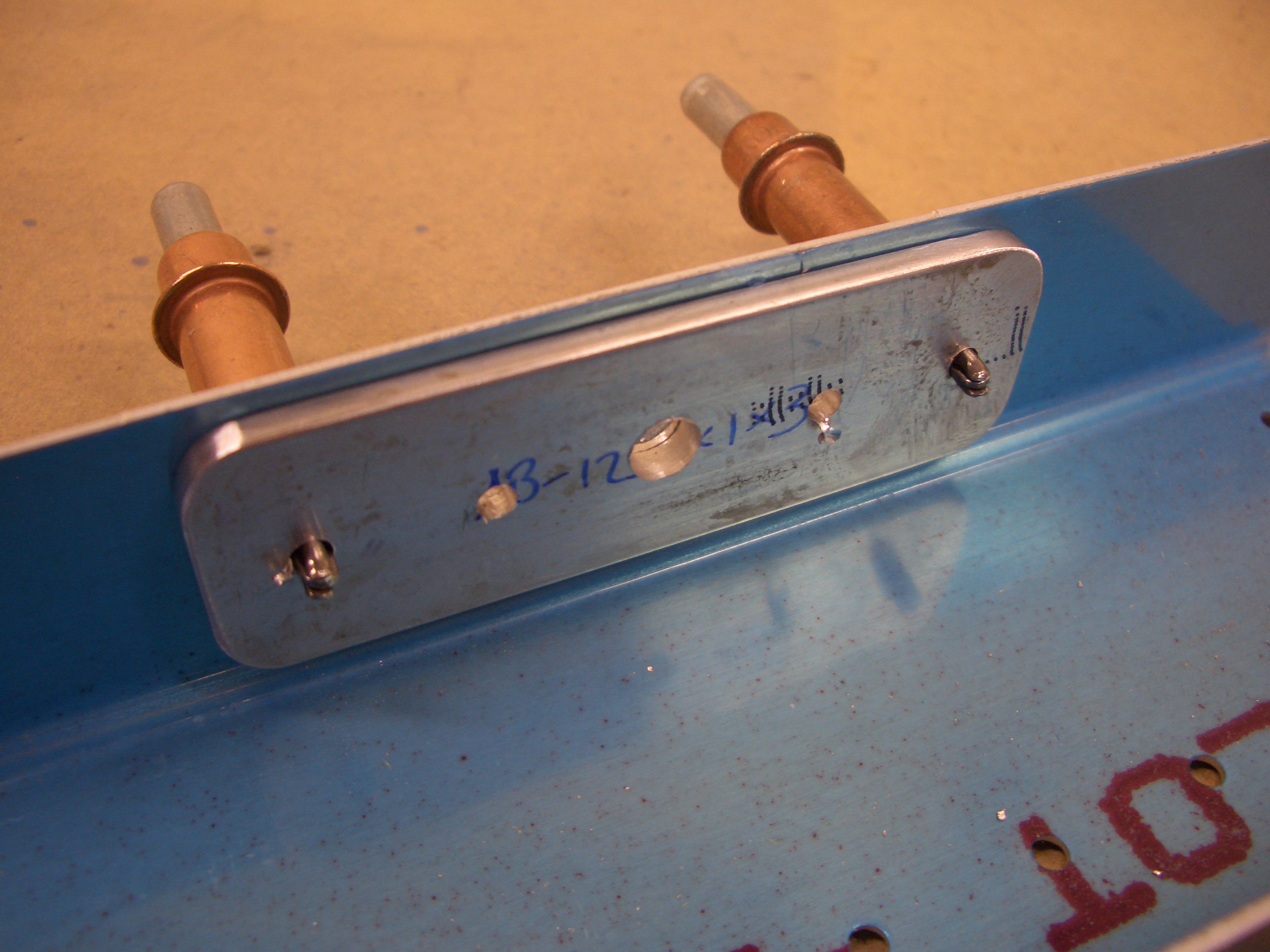
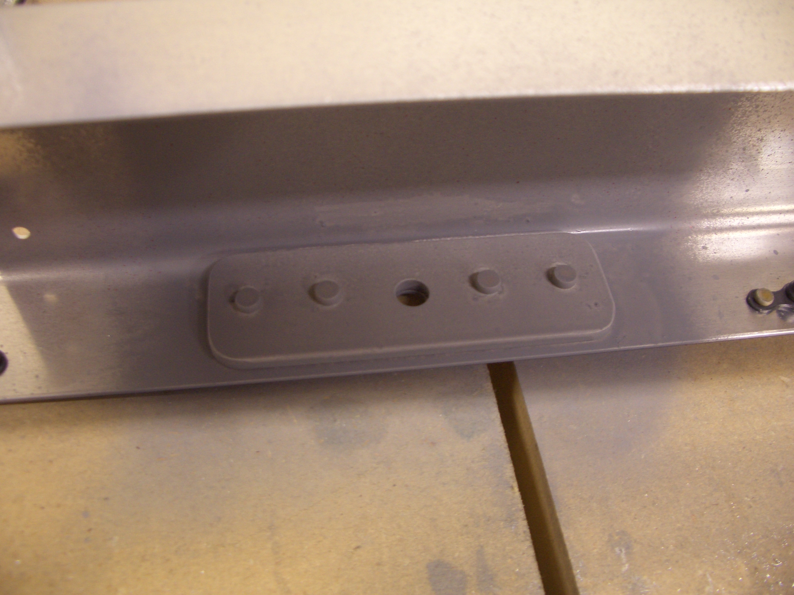
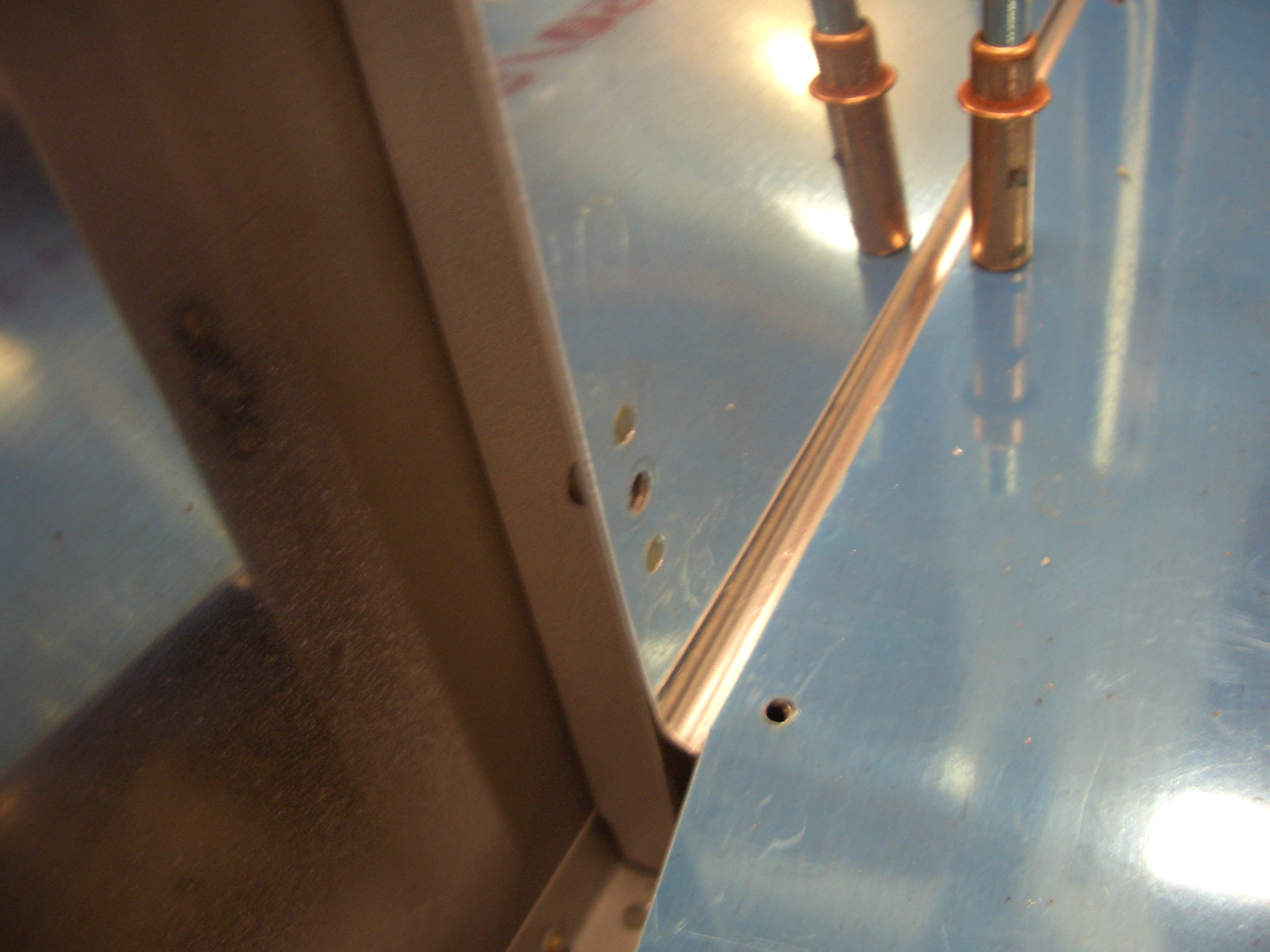
Since I’m going to mount the ELT on the Van’s mounting bracket on the right side wall behind F-706, but put the antenna behind the roll bar, I decided to run the antenna cable behind the baggage sidewall.  I drilled a couple of 3/8″ holes in F-706 and F-724 below F-786B.  The cable will also run behind the flap cover and then come up through F-786B right behind F-705.   I then fished a piece of safety wire through both holes so that I can later pull the coax through. This would have been easier to do before riveting on the side walls, but it wasn’t too bad.

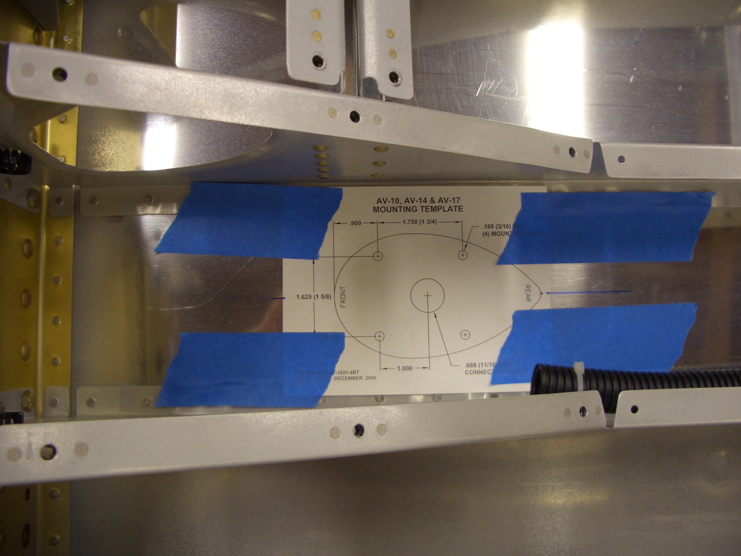
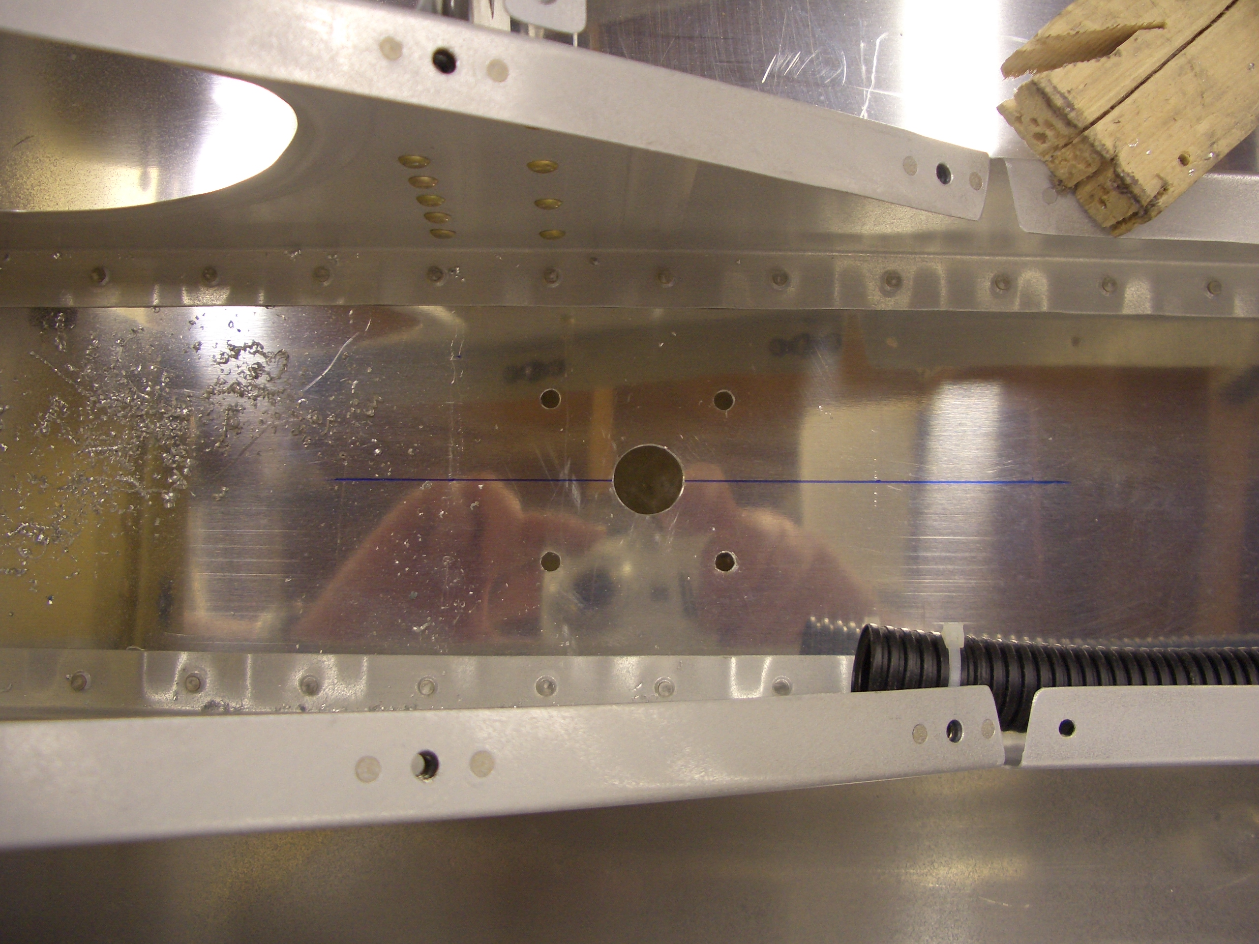
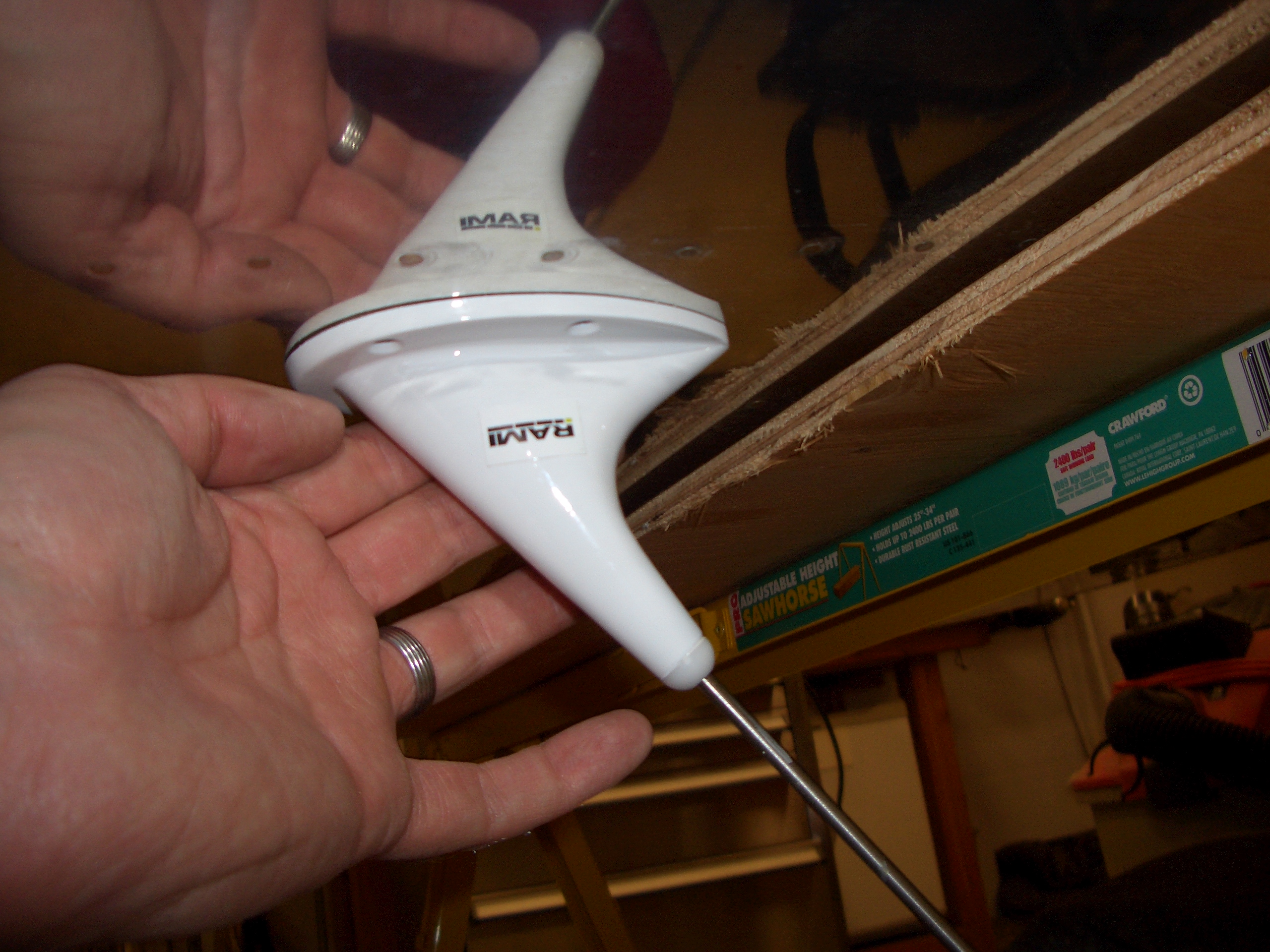
Update: I ended up not mounting the ELT on Van’s mounting bracket and put the antenna under the empennage fairing.

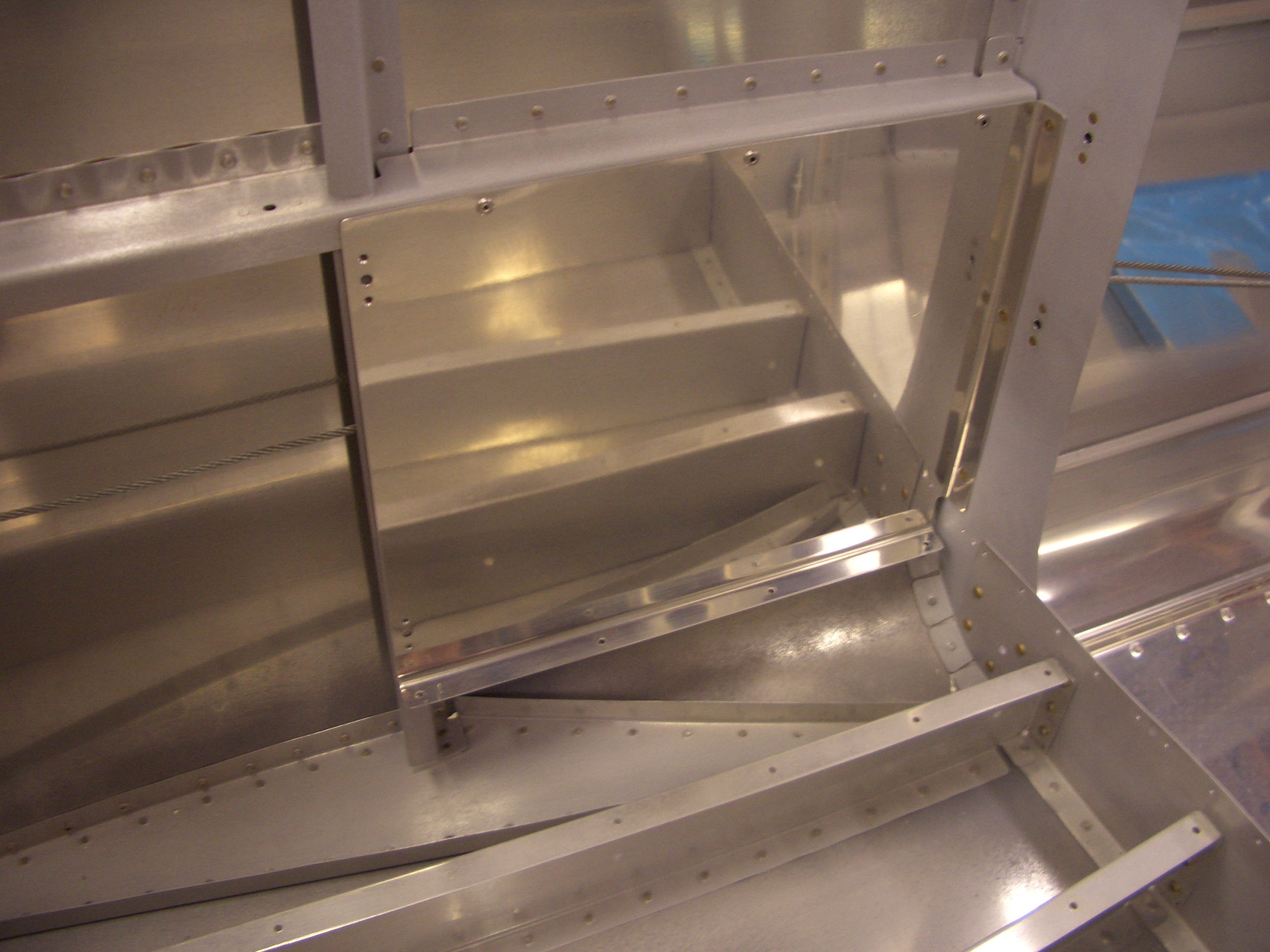
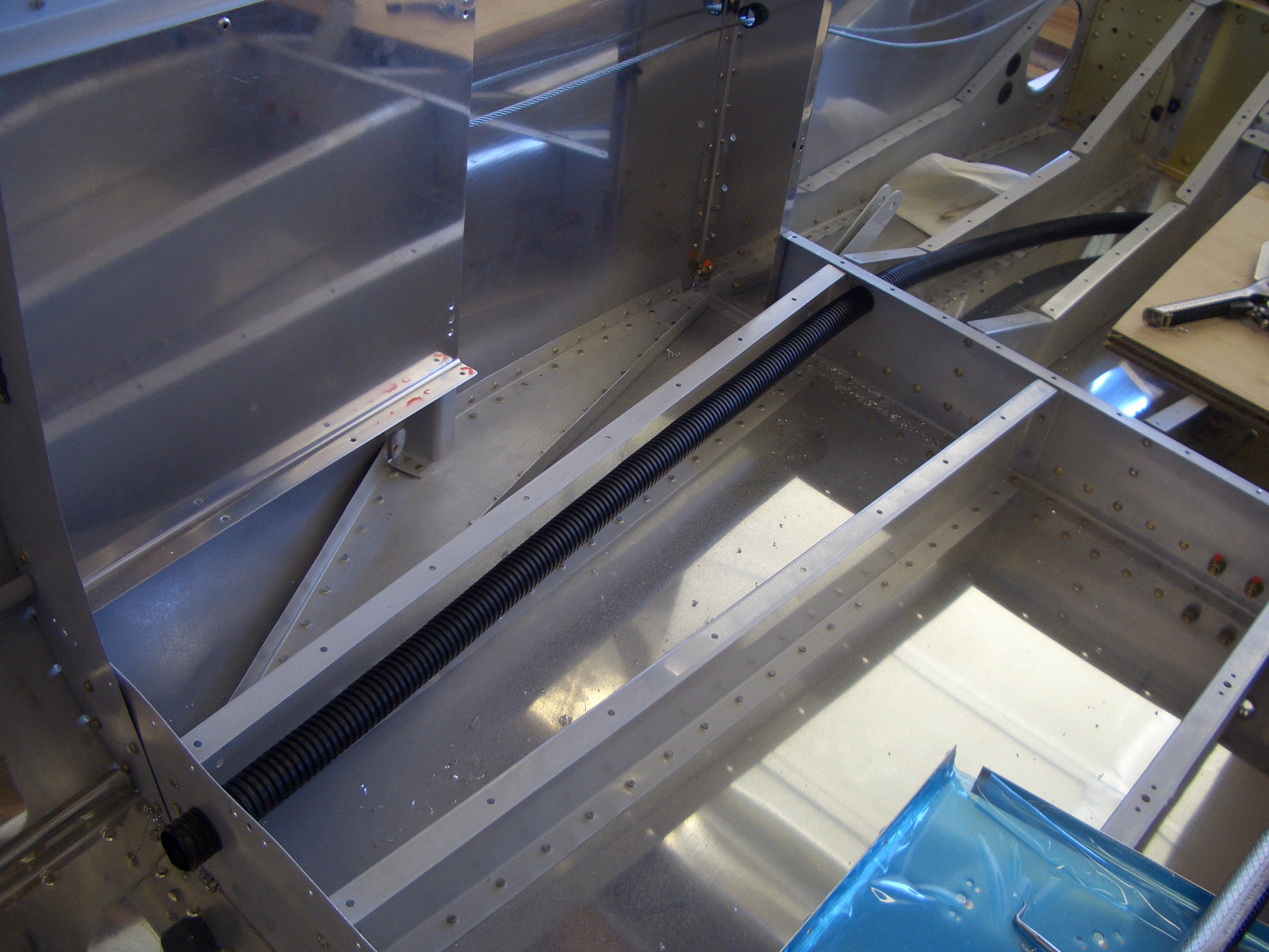
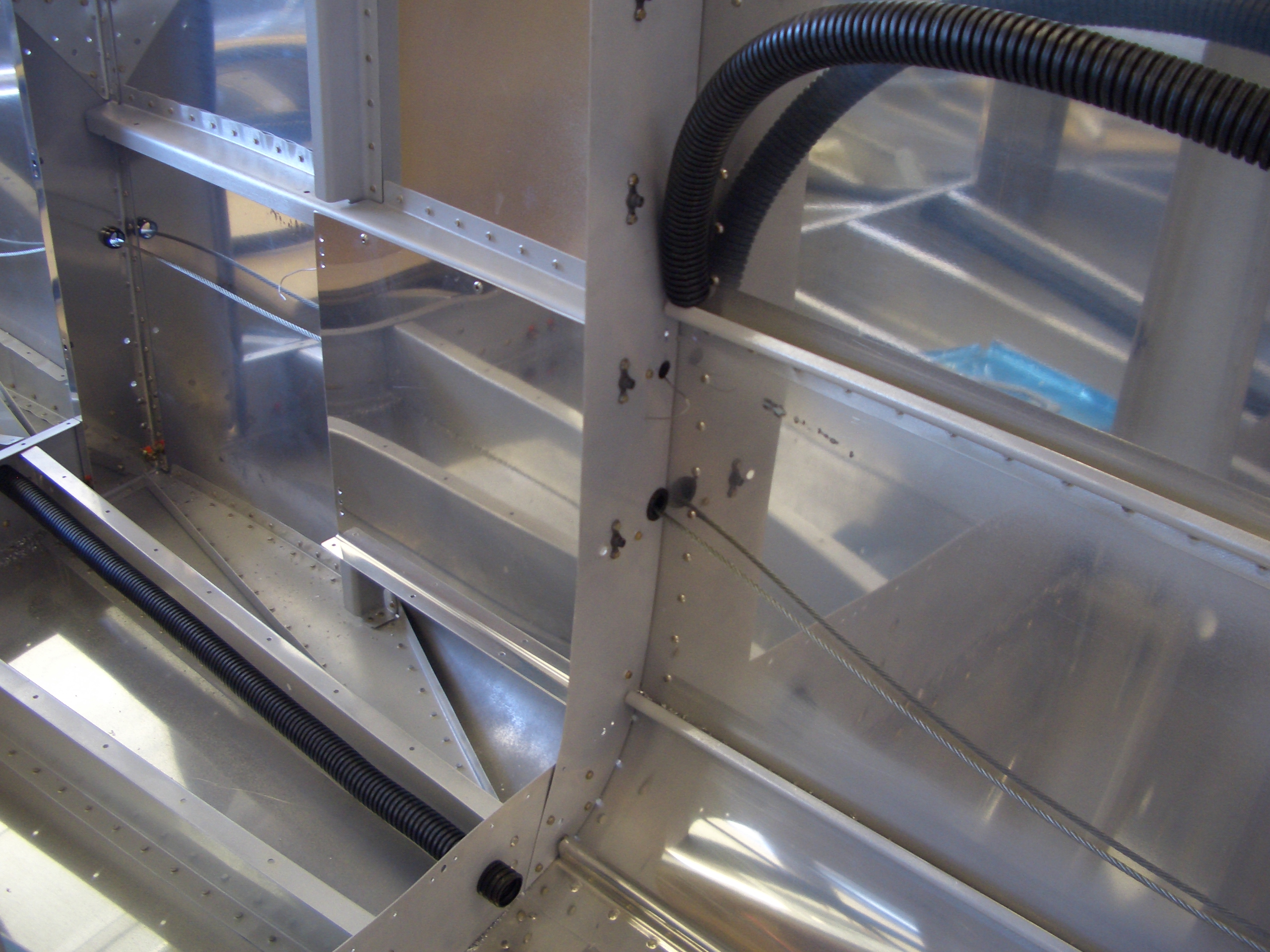
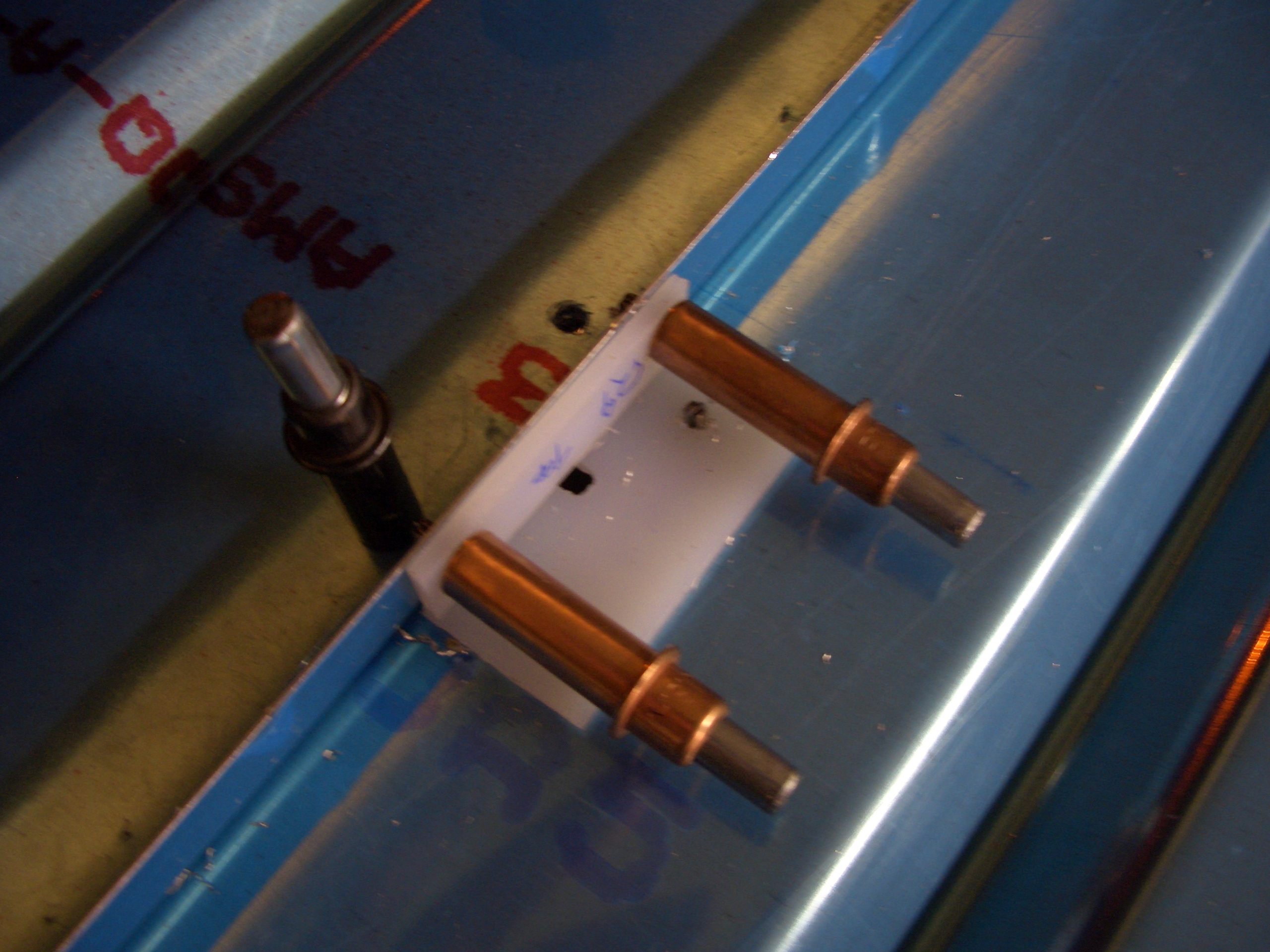
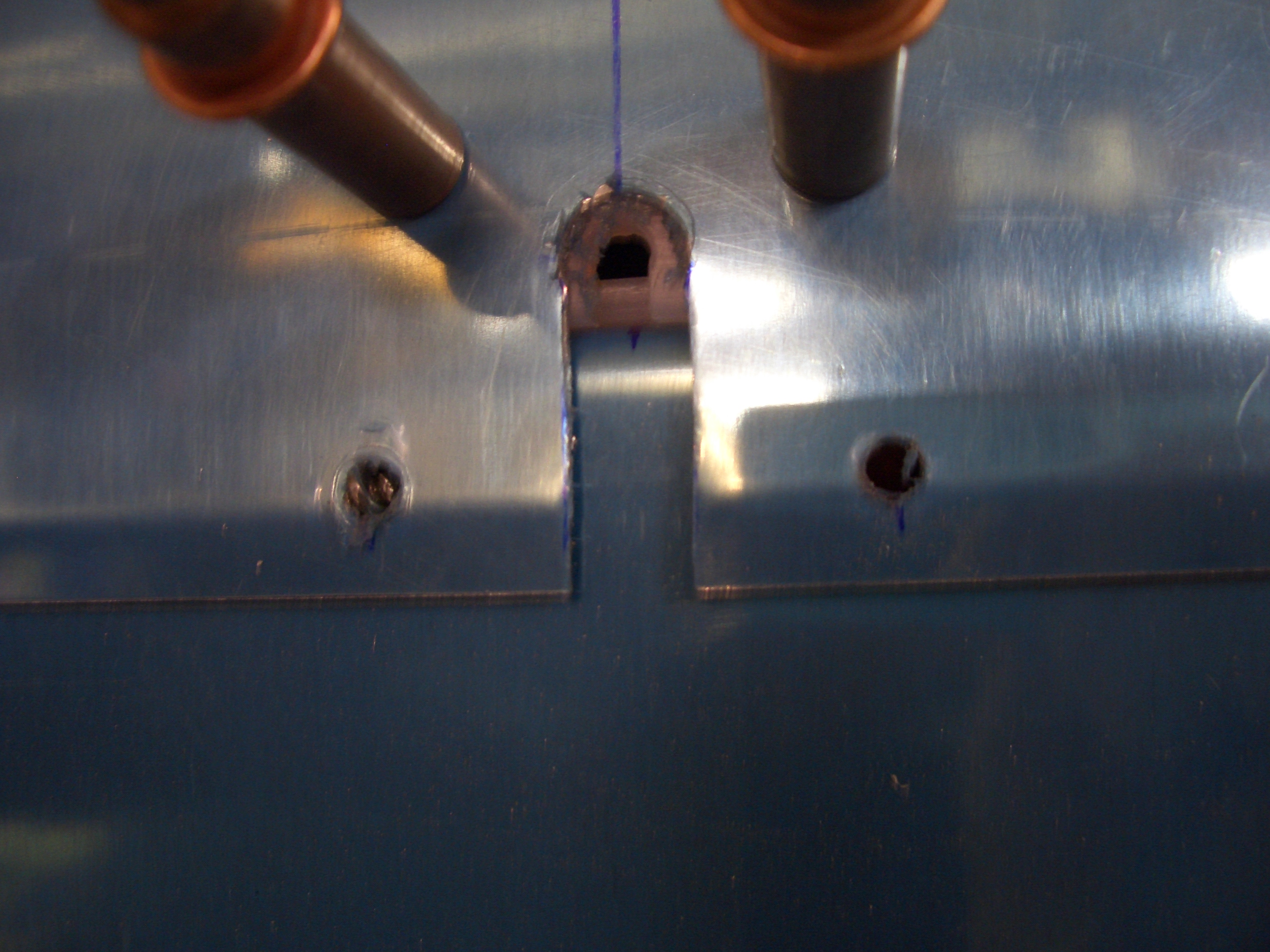
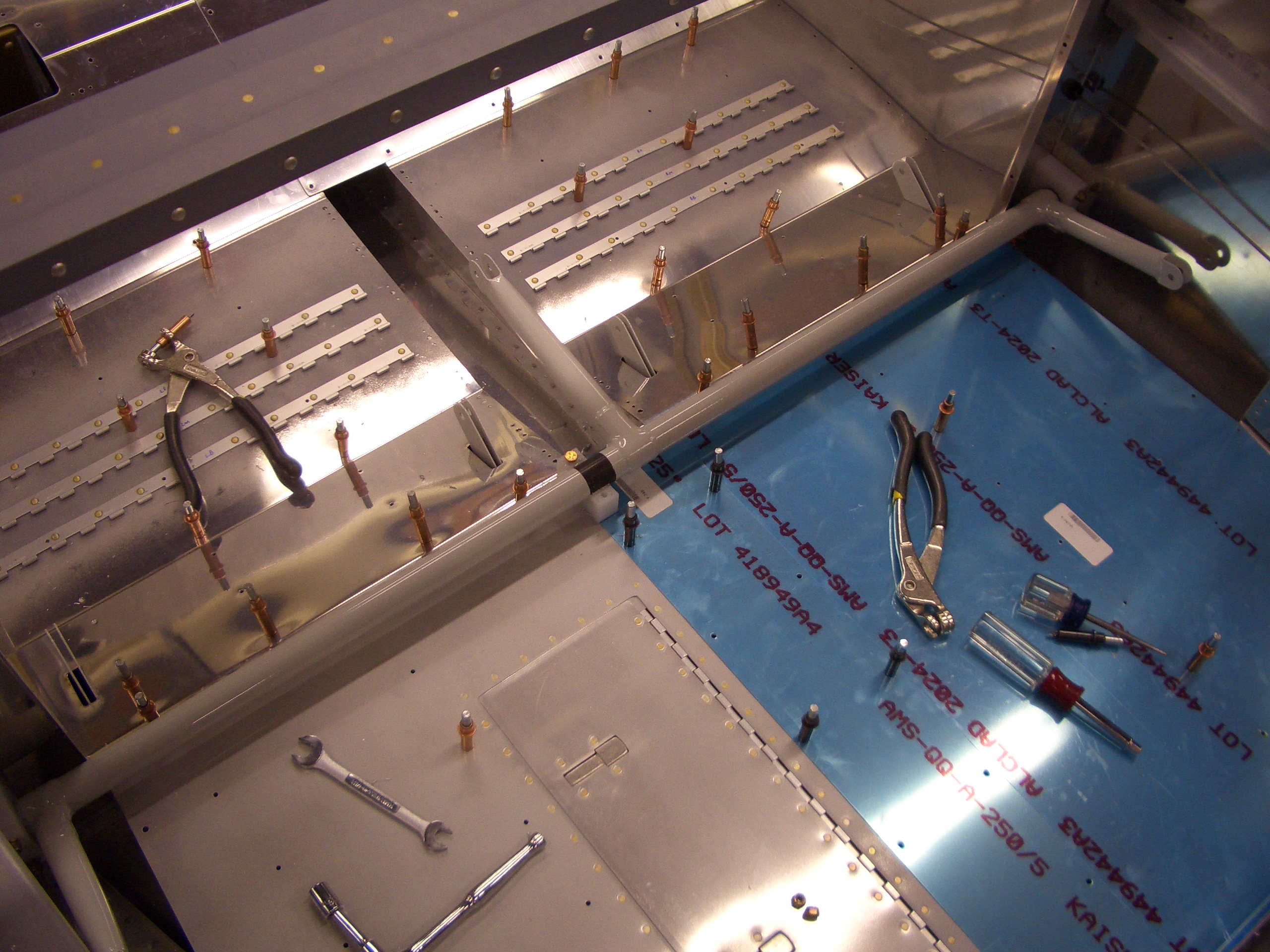
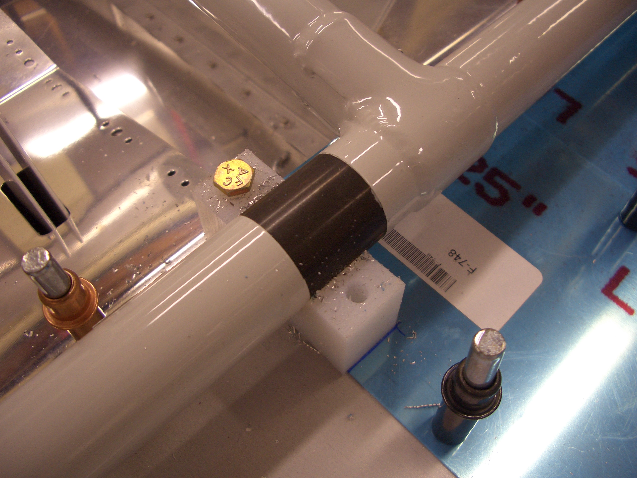
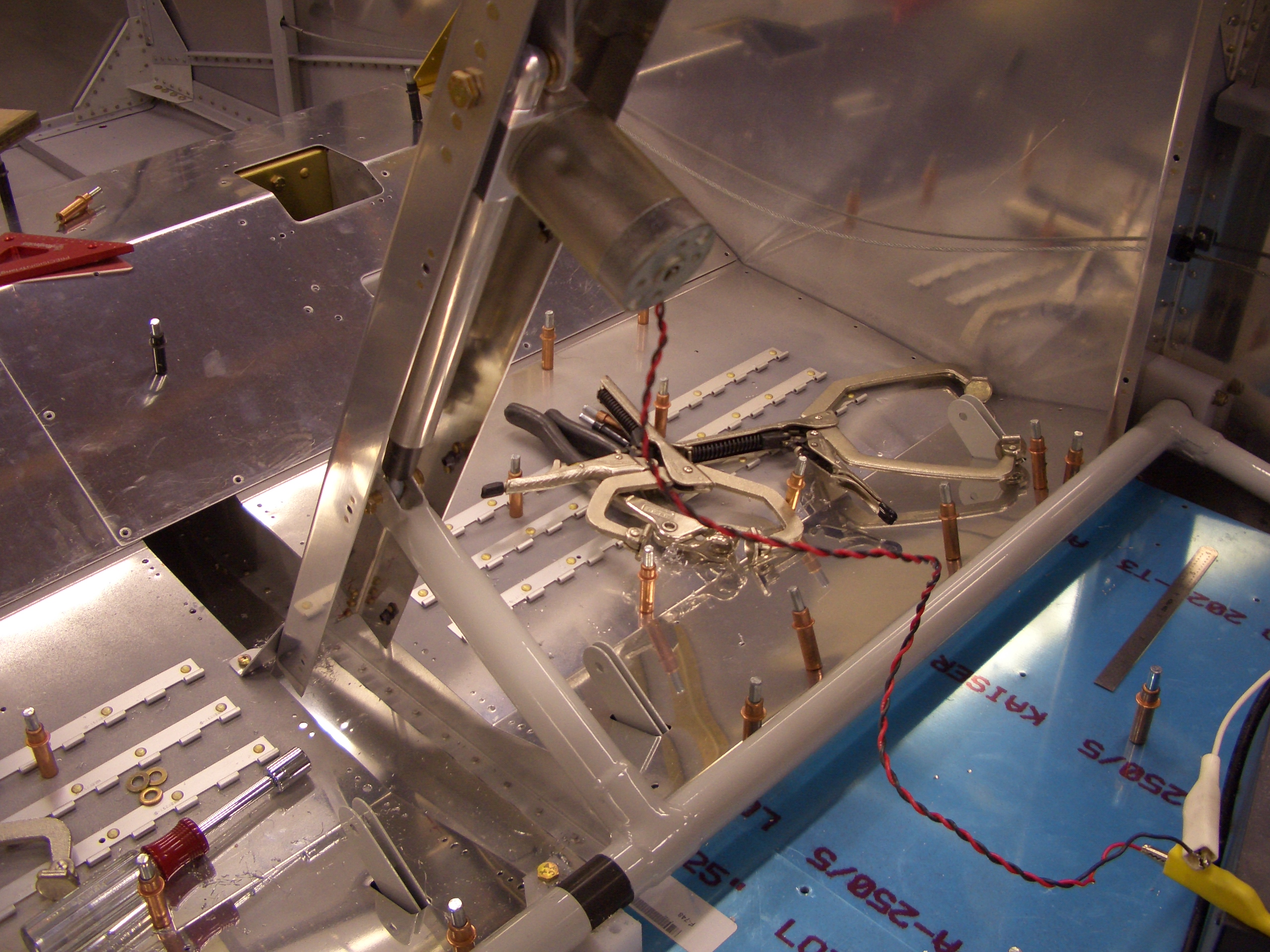
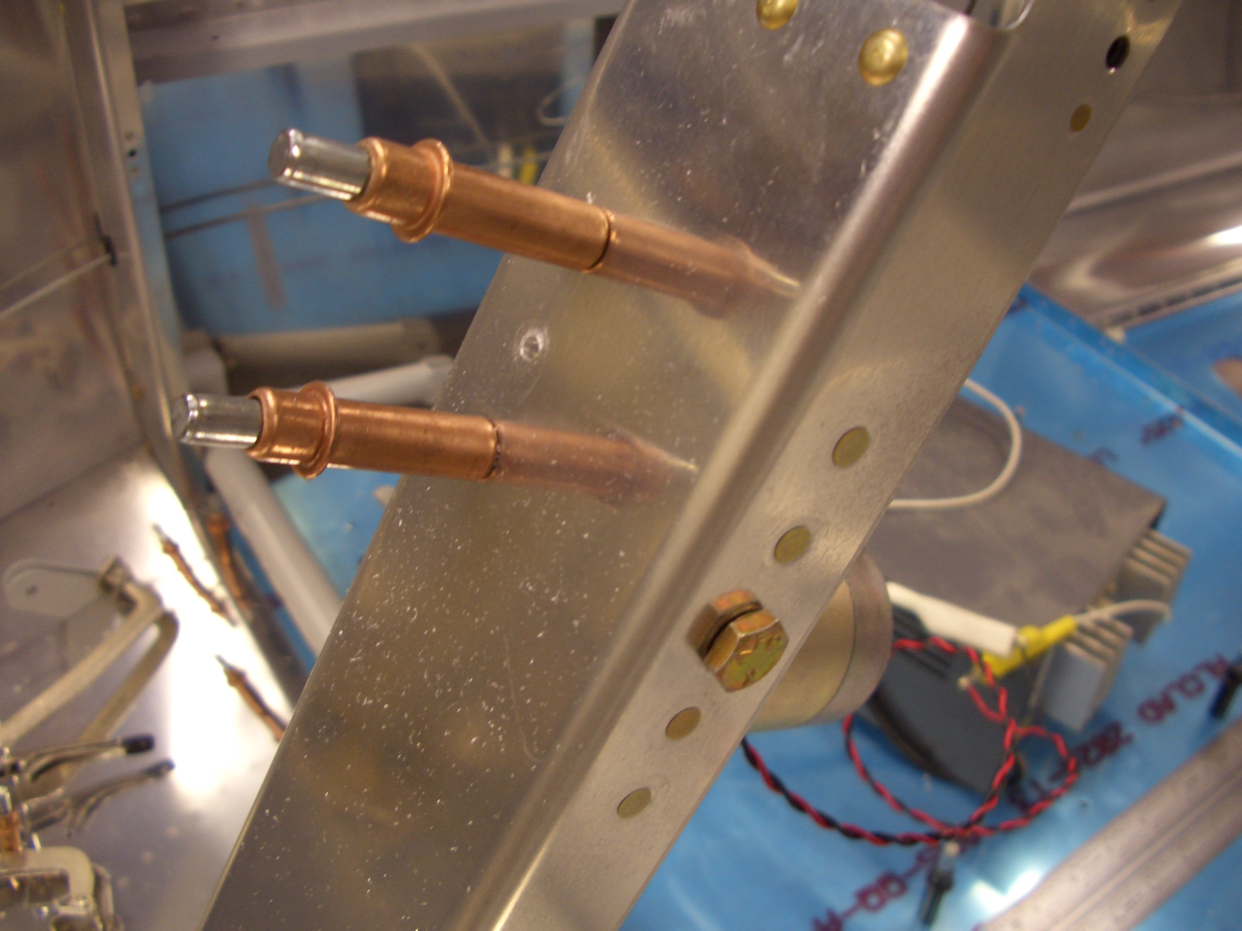
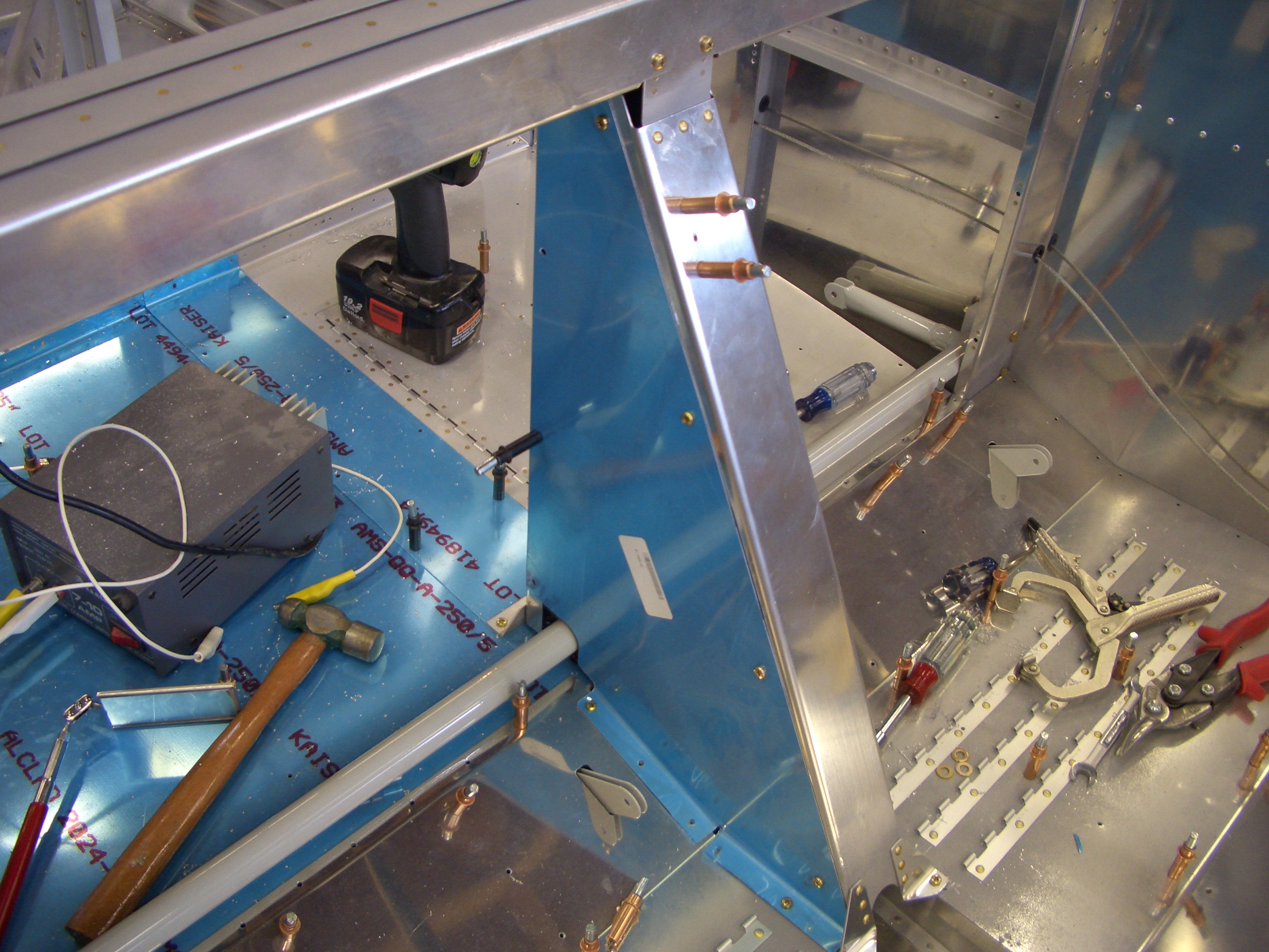
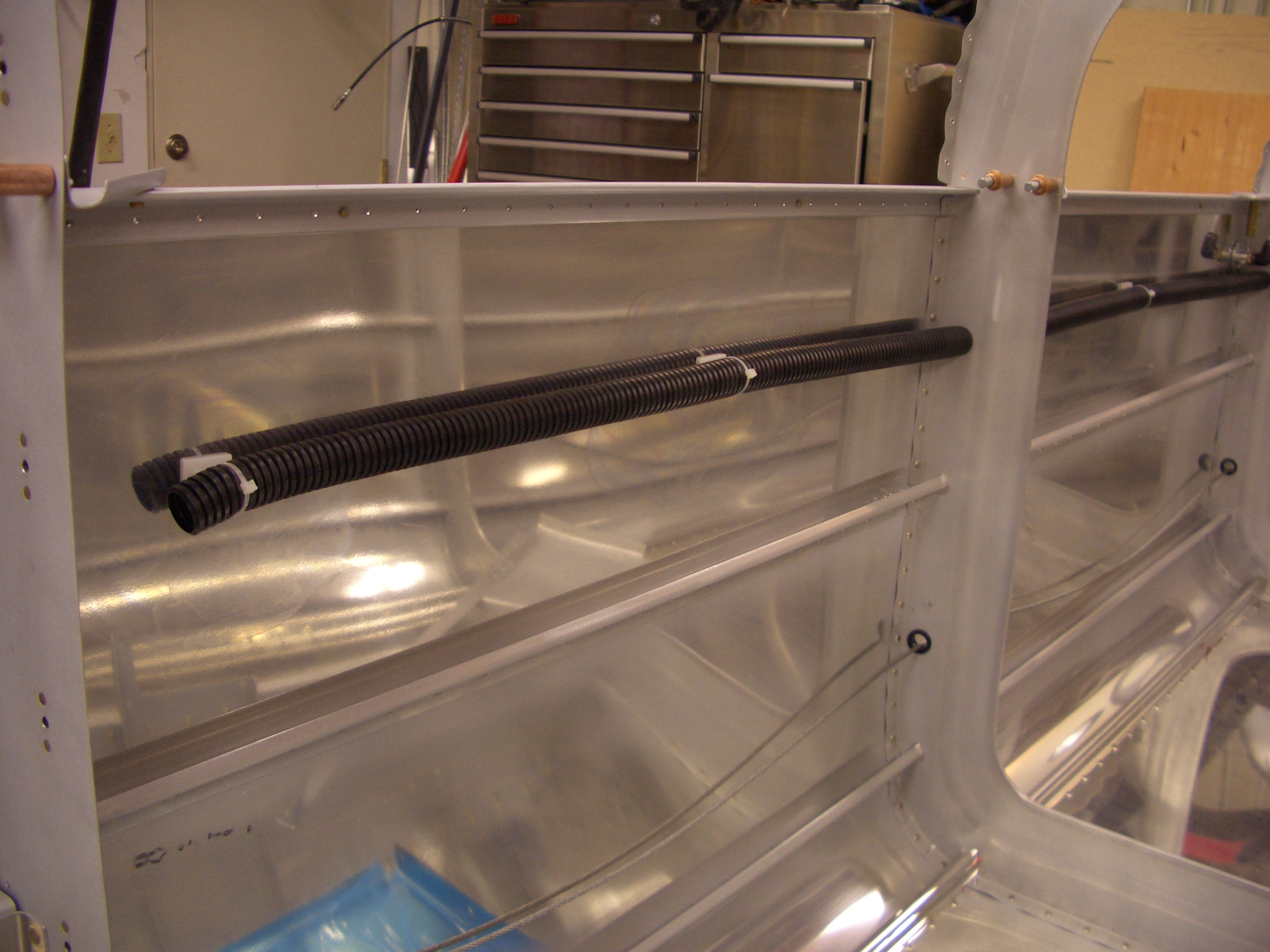
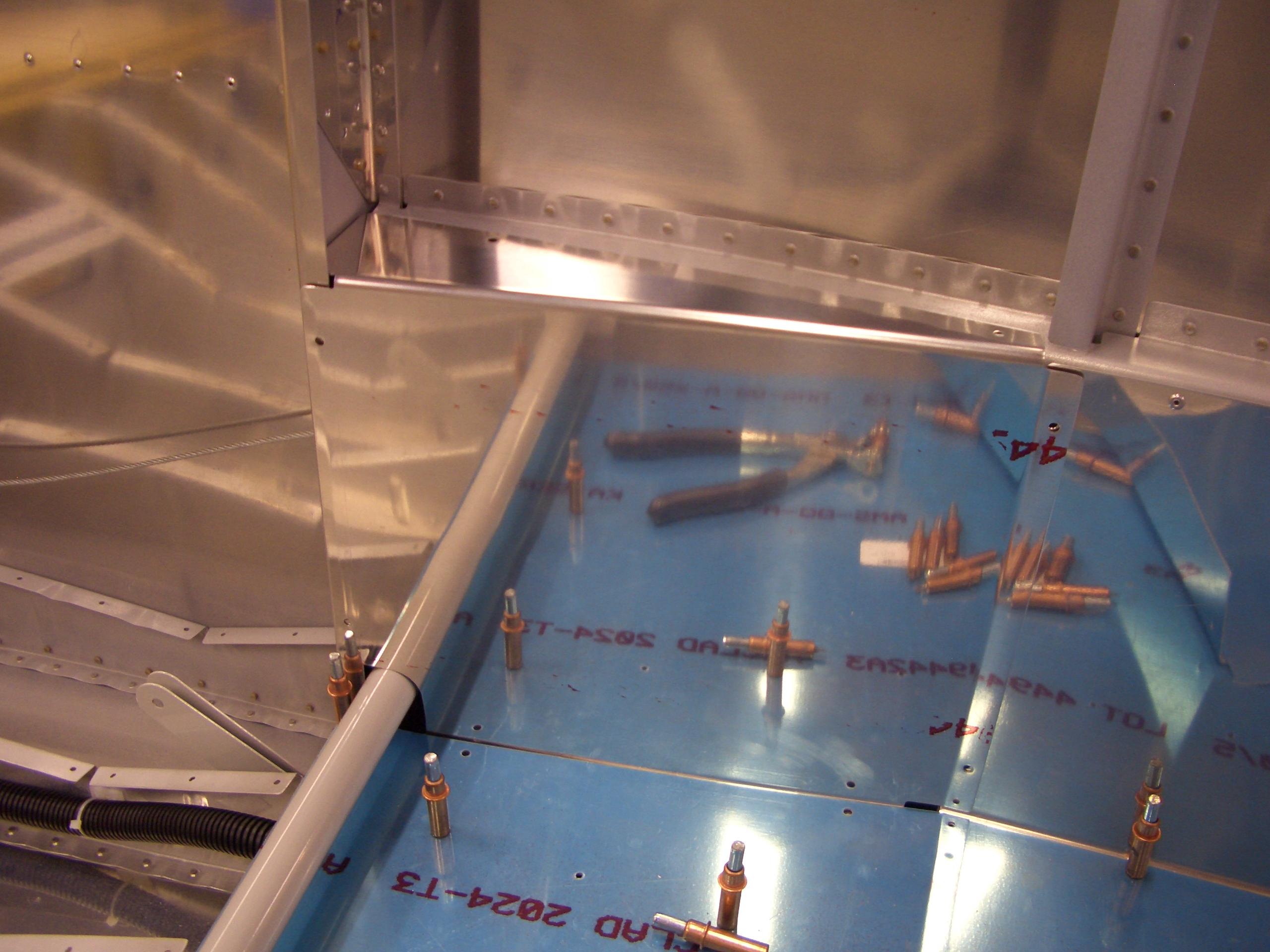
Next up, I drilled 3/4″ holes through F-705A and F-706 on both sides of the fuselage and ran conduit.  I’ll put a zip tie anchor on the rib and cushion the holes with proseal before buttoning this up.

On the right side, the wires will exit the lower conduit and come up the back of F-706 through an adel clamp to keep them away from the rudder cable.  The ELT wires (other than the antenna cable will separate here and go to the ELT bracket.  The trim and tail strobe wires will continue up and enter the conduit shown in the upper right which makes a straight shot to the tail.  I’ve intentionally left this conduit long right now while I determine how to terminate it.

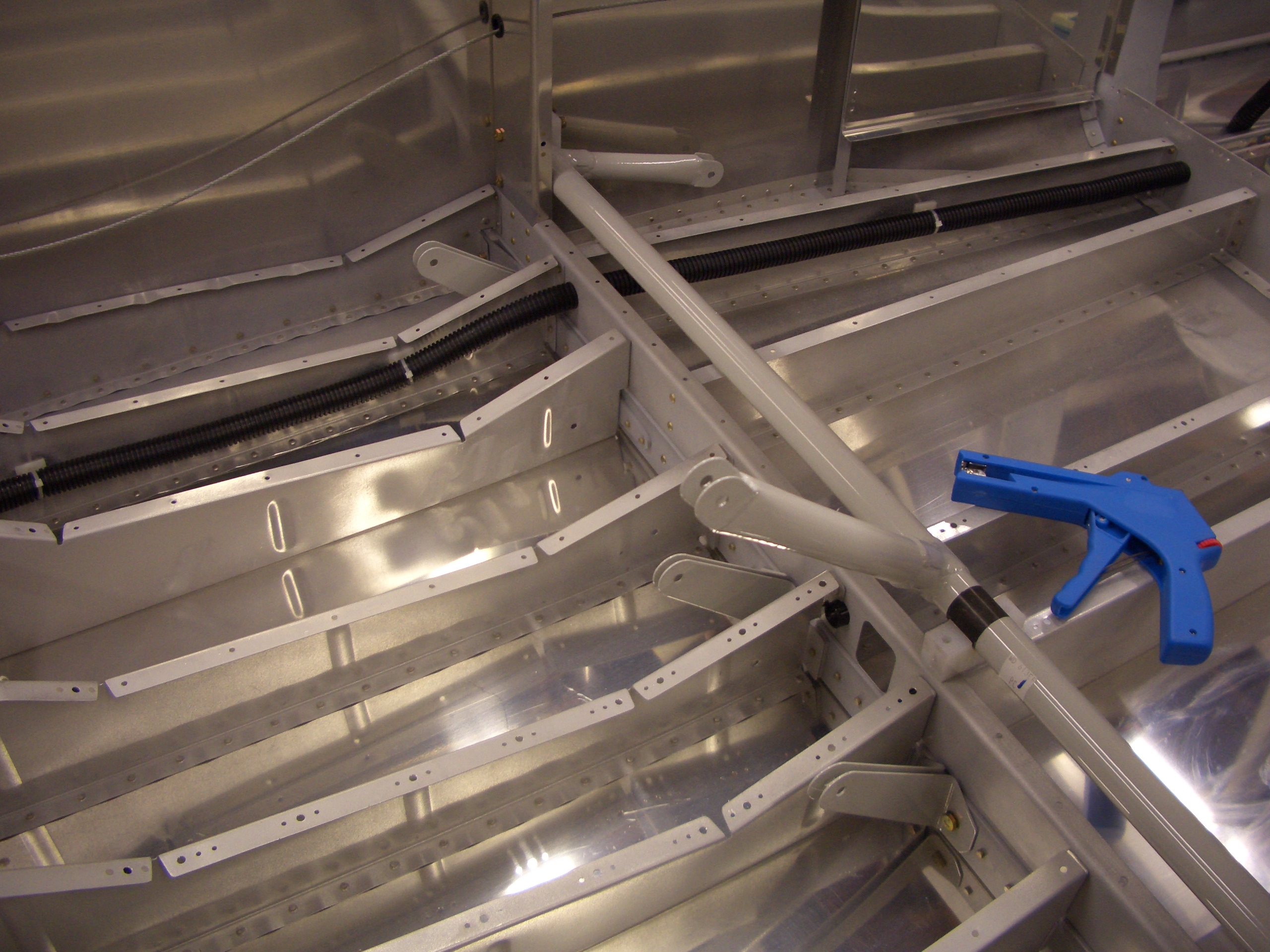
Here you can see that the conduit passes through F-707, F-708, and F-710.  The wire bundle will then separate with the tail strobe wires dropping down to penetrate F-711 and F-712 and into the rudder while the trim servo wires will make their way up and into the elevator.  I put the conduit up high like this to keep it about 2′ from the Dynon Skyview ADAHRS unit.

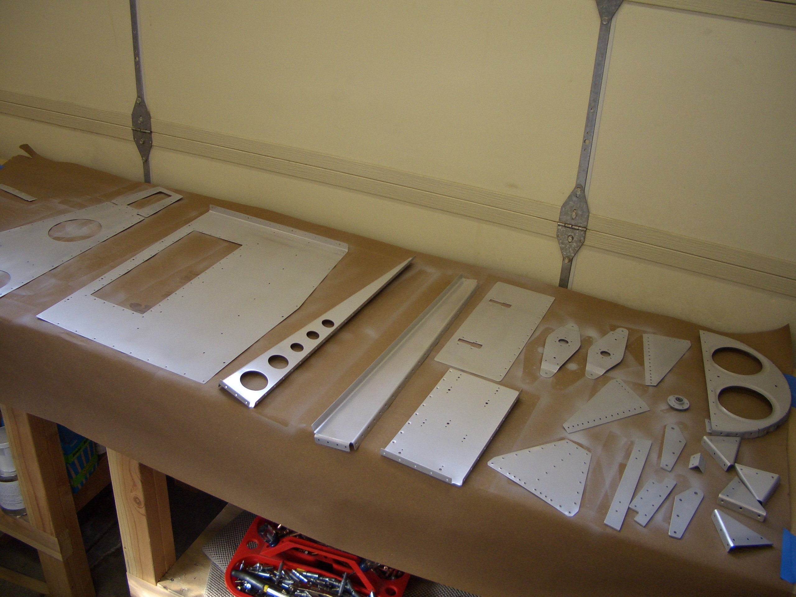
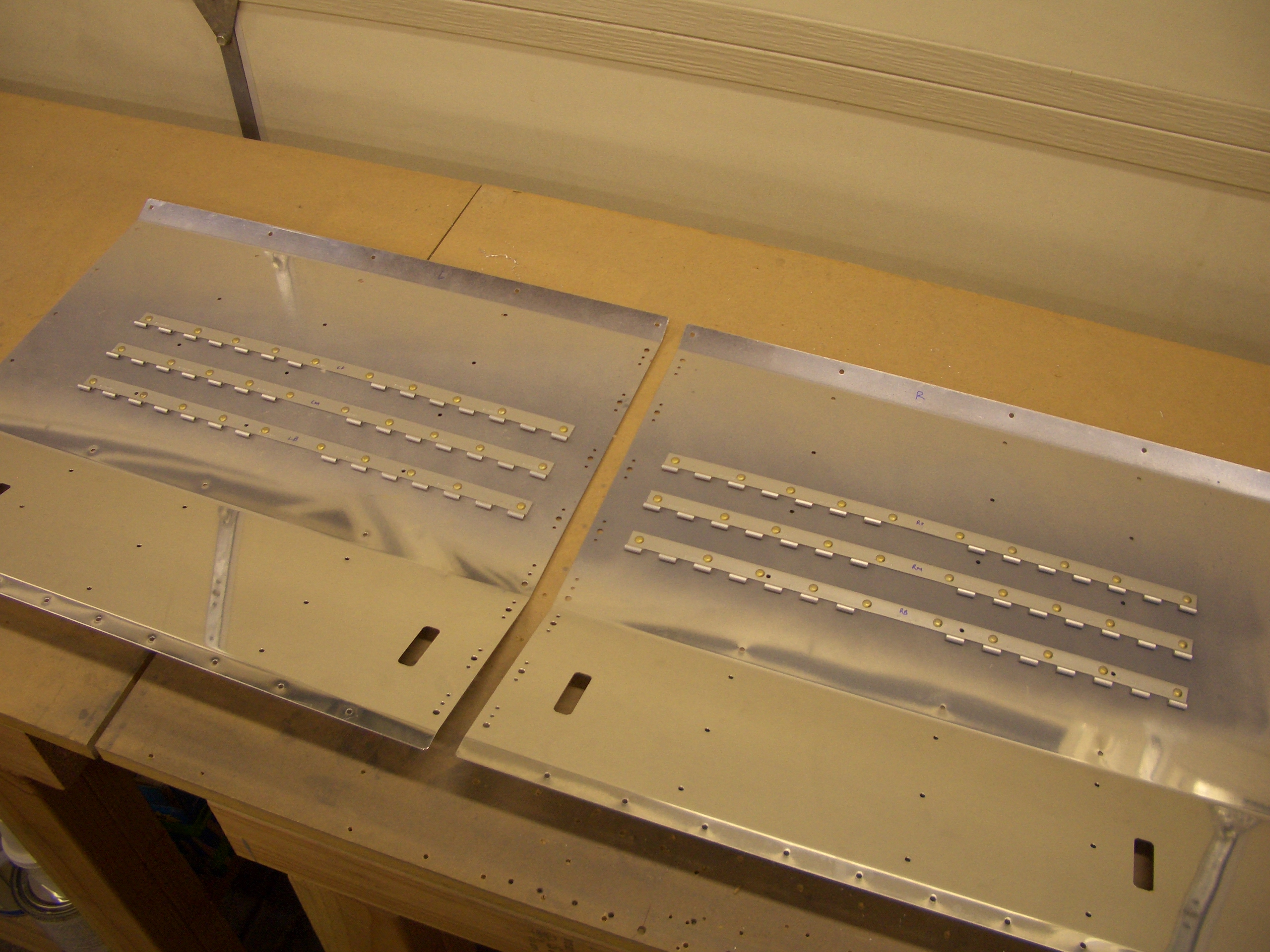
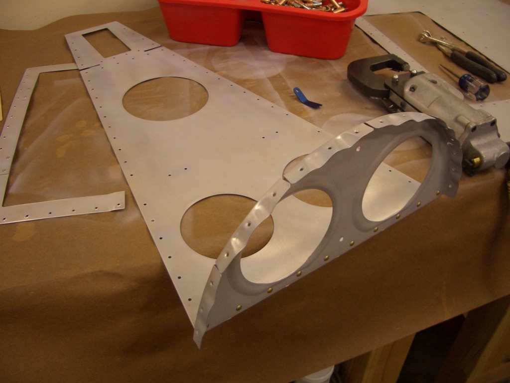
I deburred and primed all of the fuselage components that I’ve finished so far.

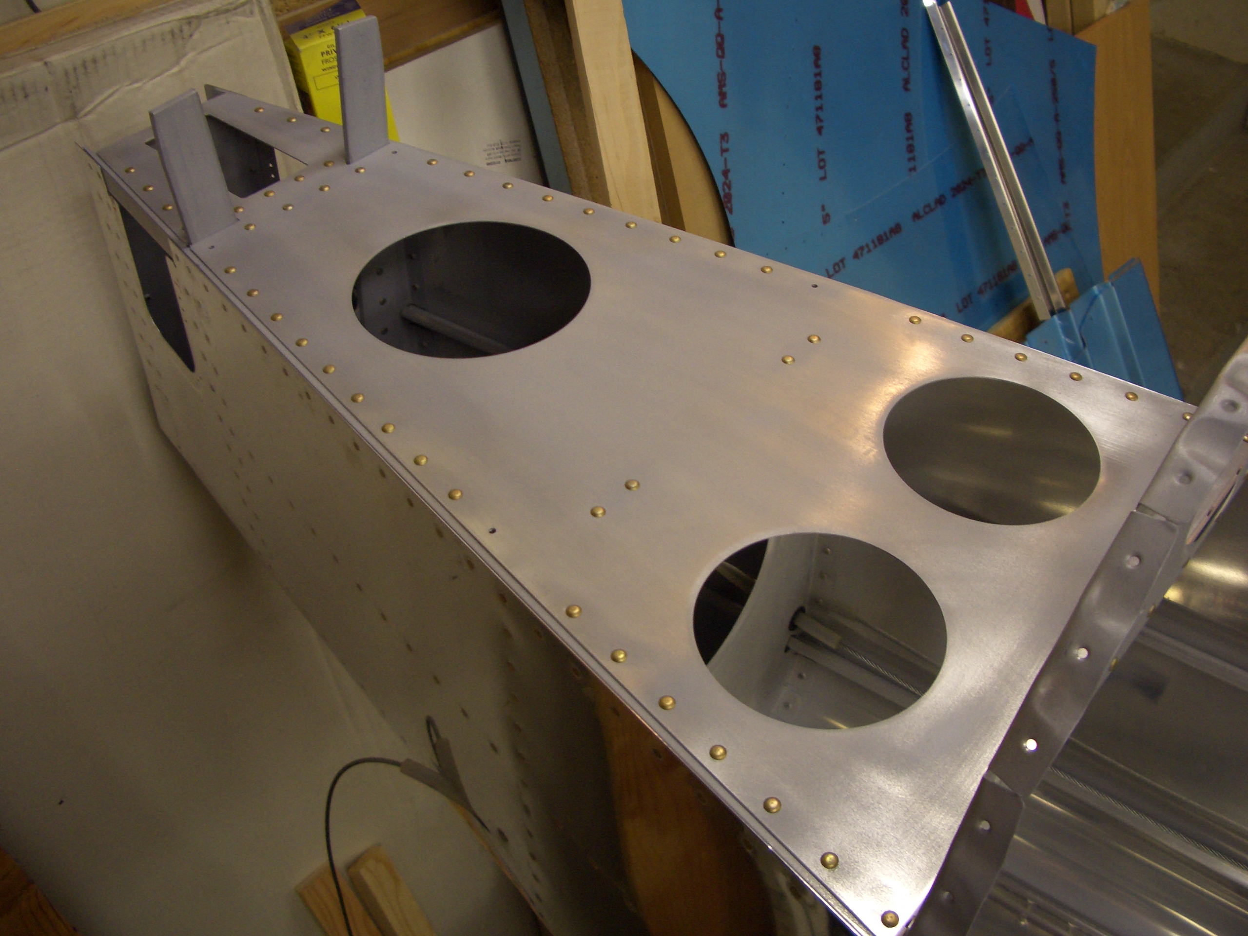
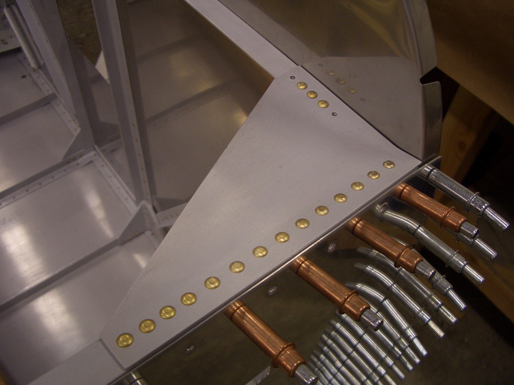
After those were dry, I riveted F-709 to the aft deck.

I then riveted the aft deck to the longerons and F-710/F-711.  There were four rivets that couldn’t be reached with the squeezer, so I’ll have to shoot/buck those.

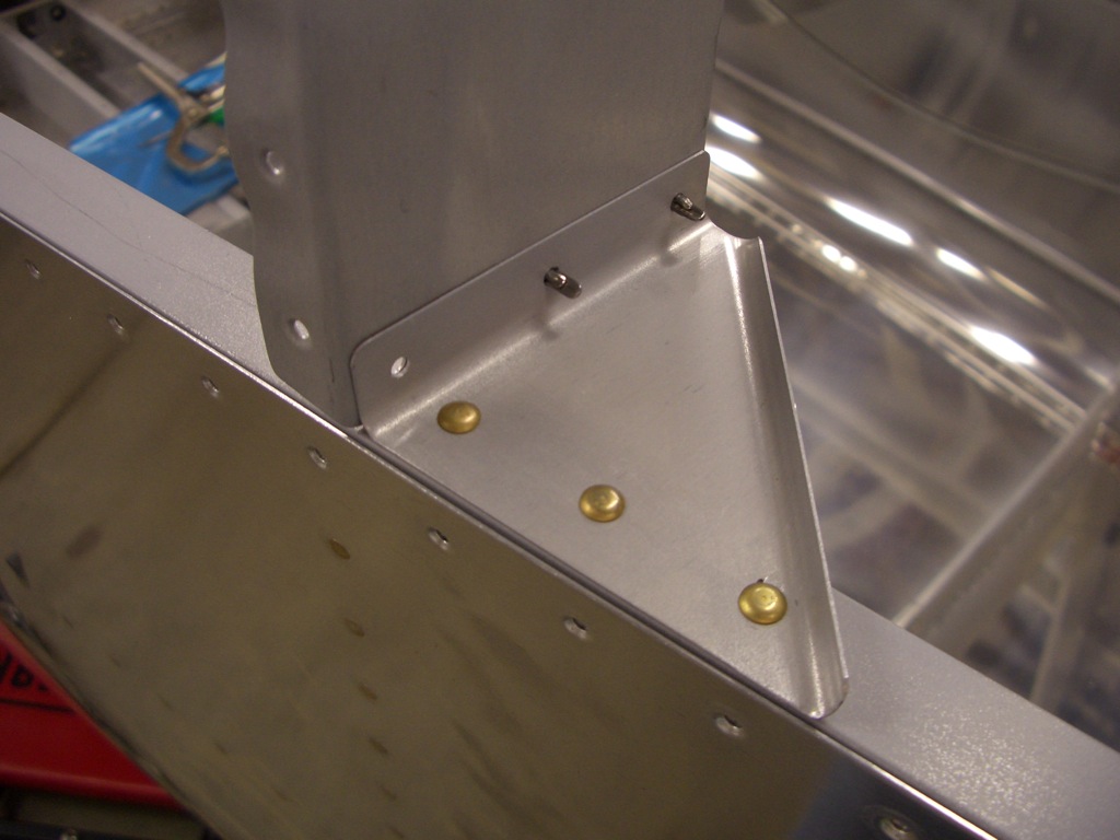
Next up, I riveted the F-695 gussets to the longerons and upper firewall stiffener.  There were two rivets on each side along the firewall stiffener that couldn’t be reached with the squeezer.  I’ll shoot those later.

I then squeezed all of the rivets that tie the bulkhead braces to the longeron.

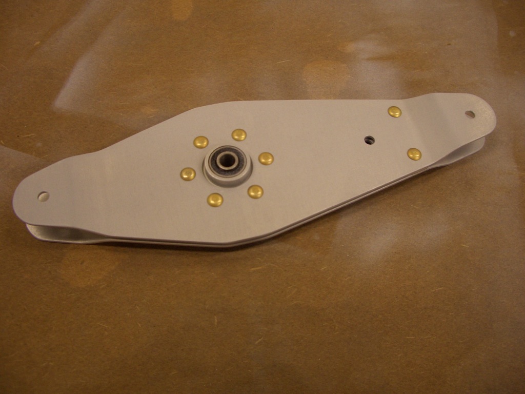
I squeezed all of the rivets that hold together the elevator bellcrank.  I’ll have to slip a washer in between the halves when hooking up the autopilot servo, but that will be easy with the washer wrenches.

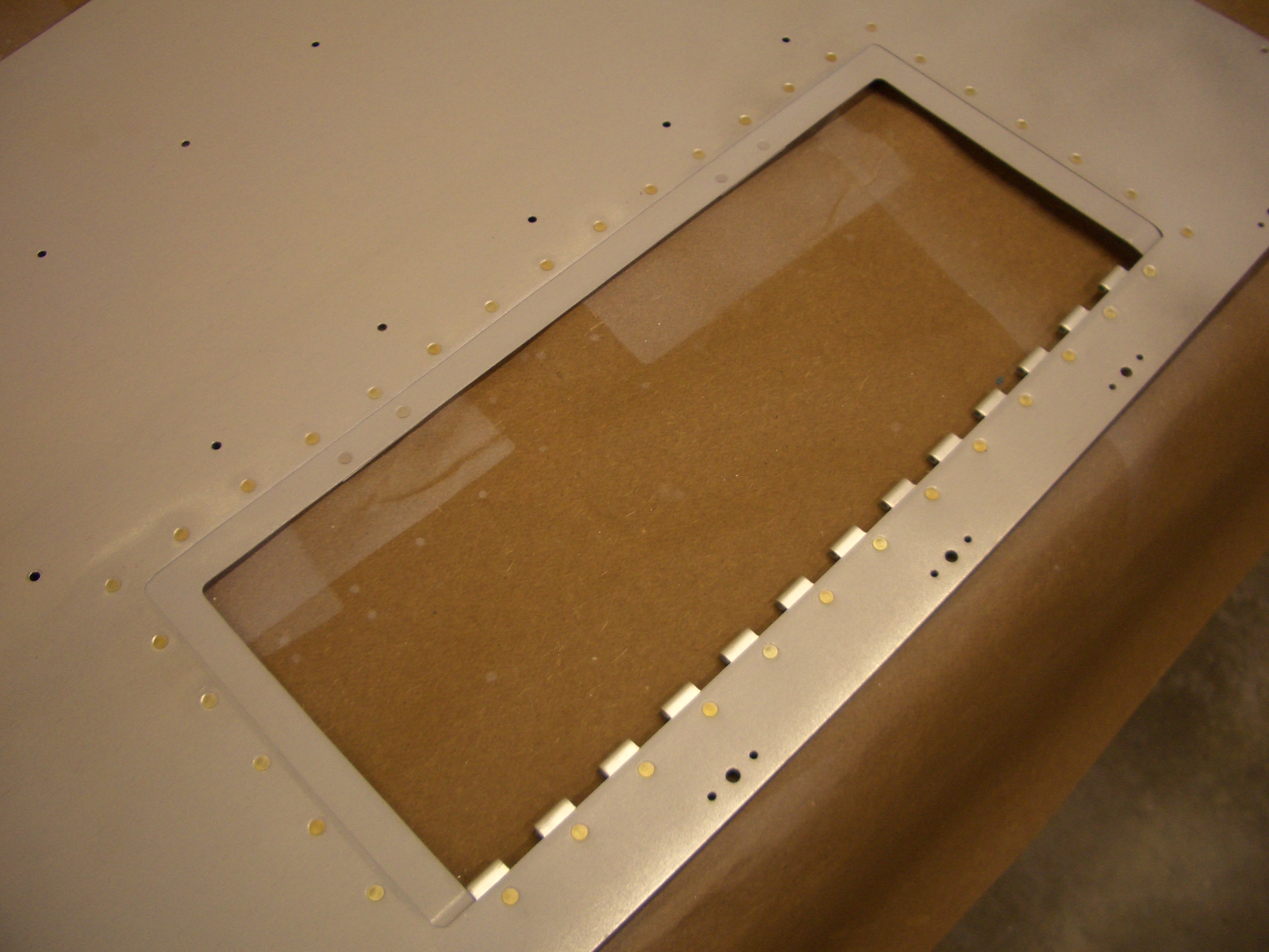
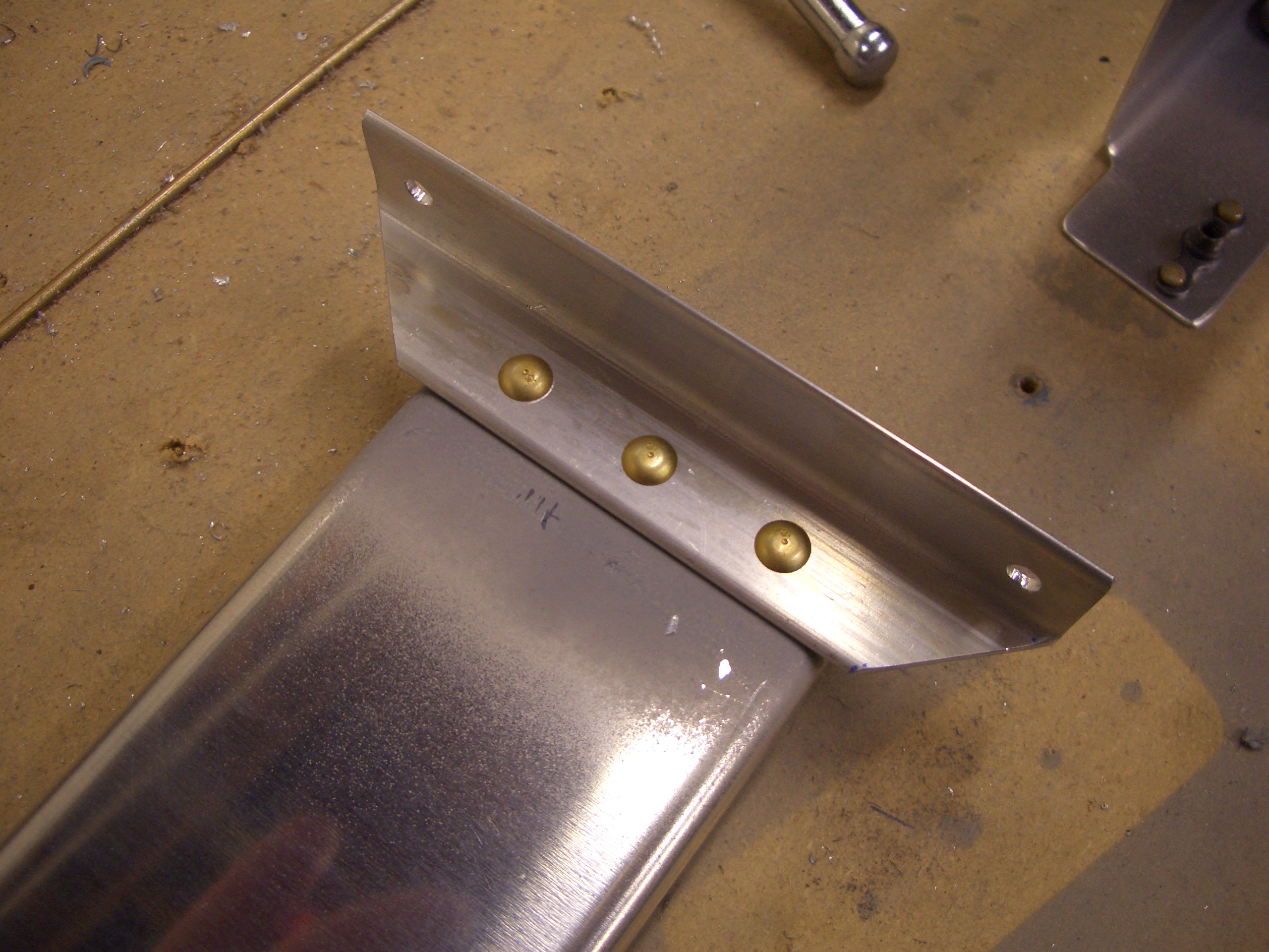
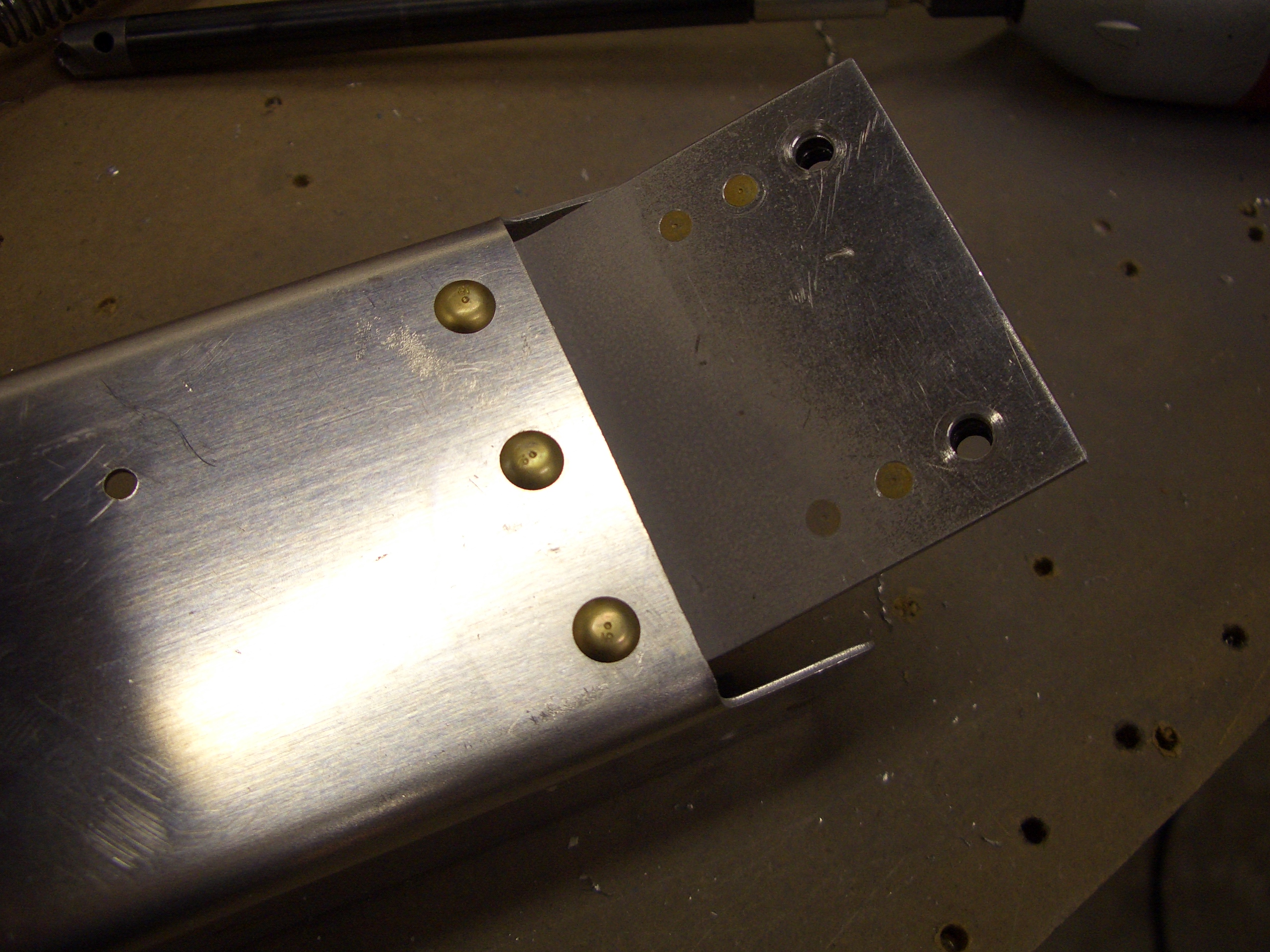
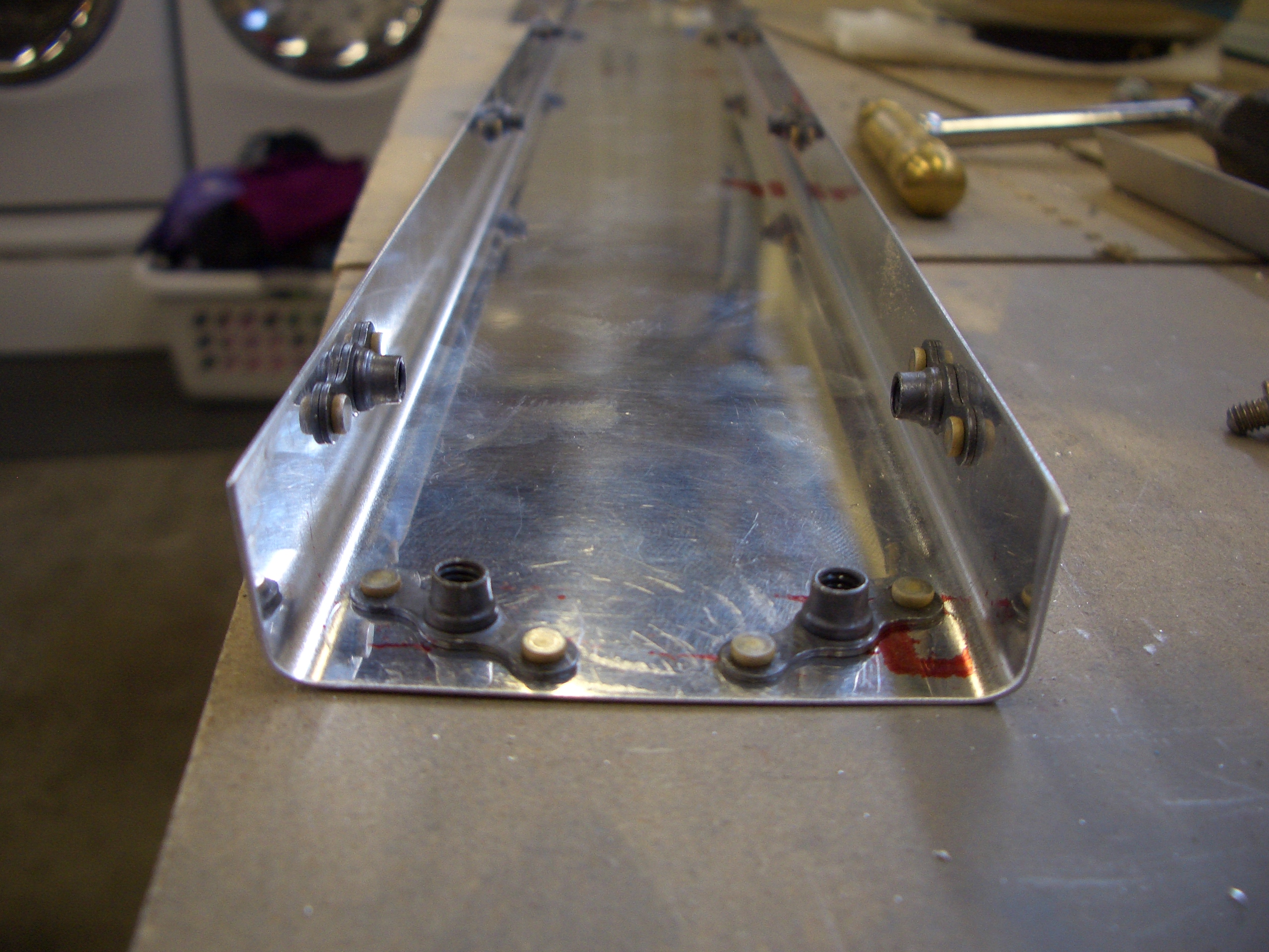
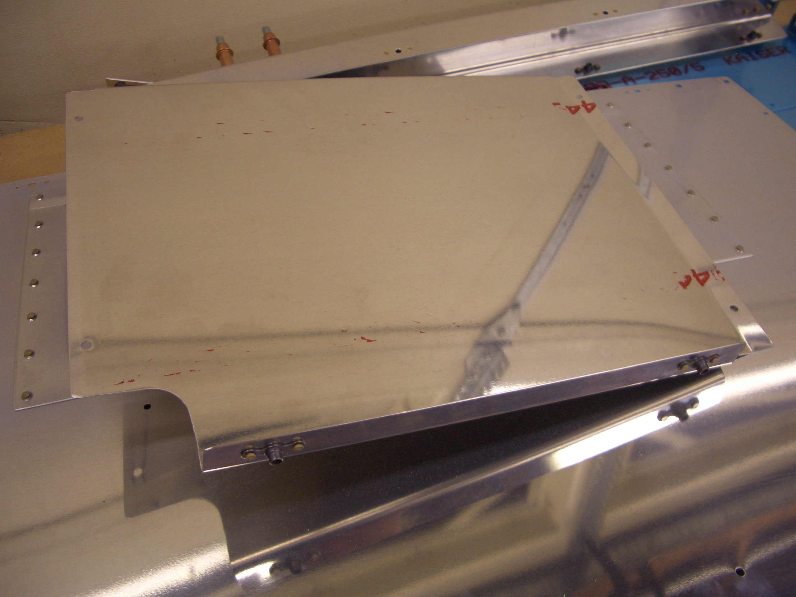
I also assembled the hatch in the left baggage floor.  Here, I’ve riveted the reinforcing ring and hinge to the floor.

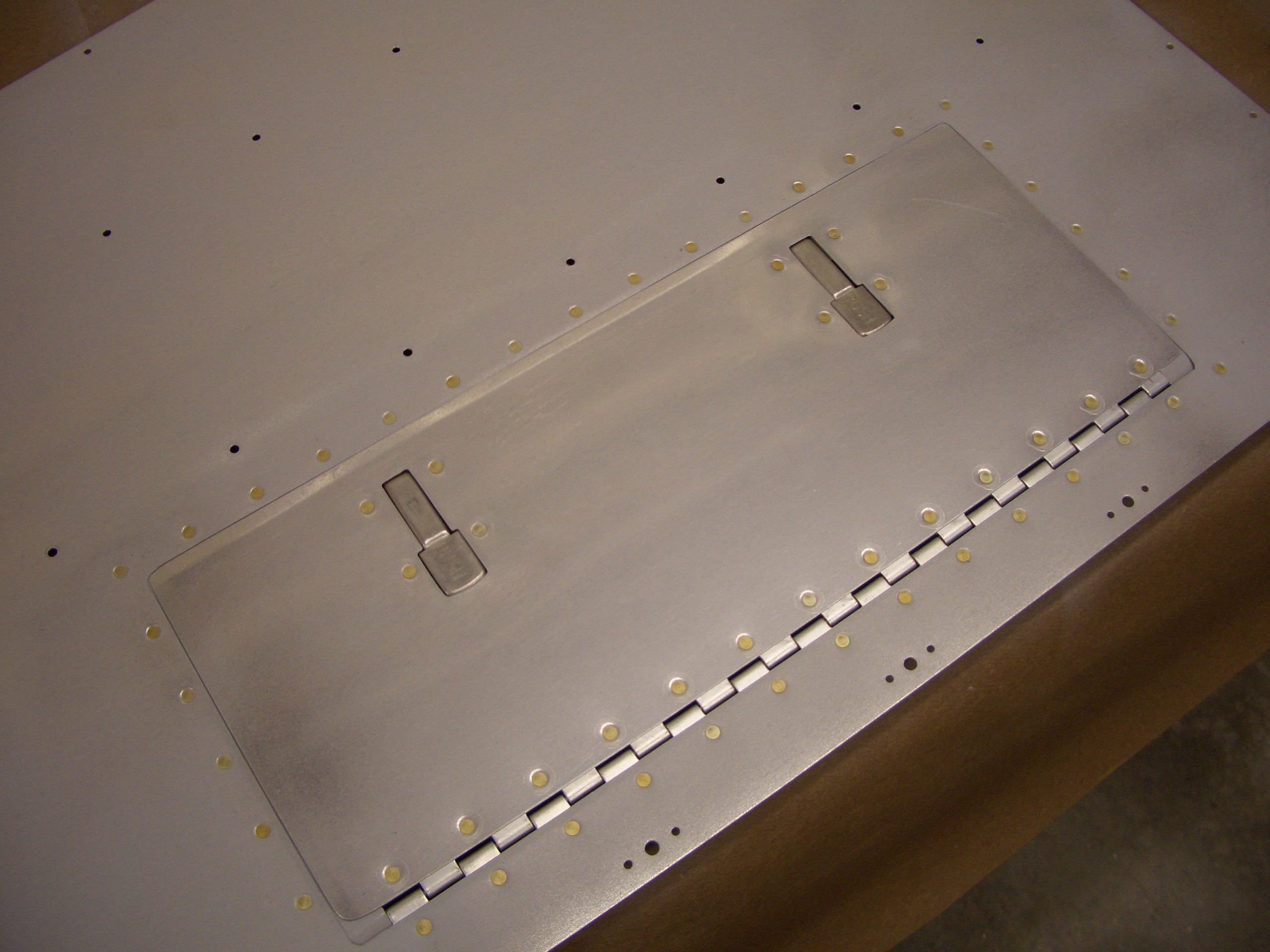
I then riveted the other part of the hinge and the hartwell latches to the hatch.  Here is how it looks closed.  The hatch closes firmly enough against the flange that it shouldn’t rattle in flight.

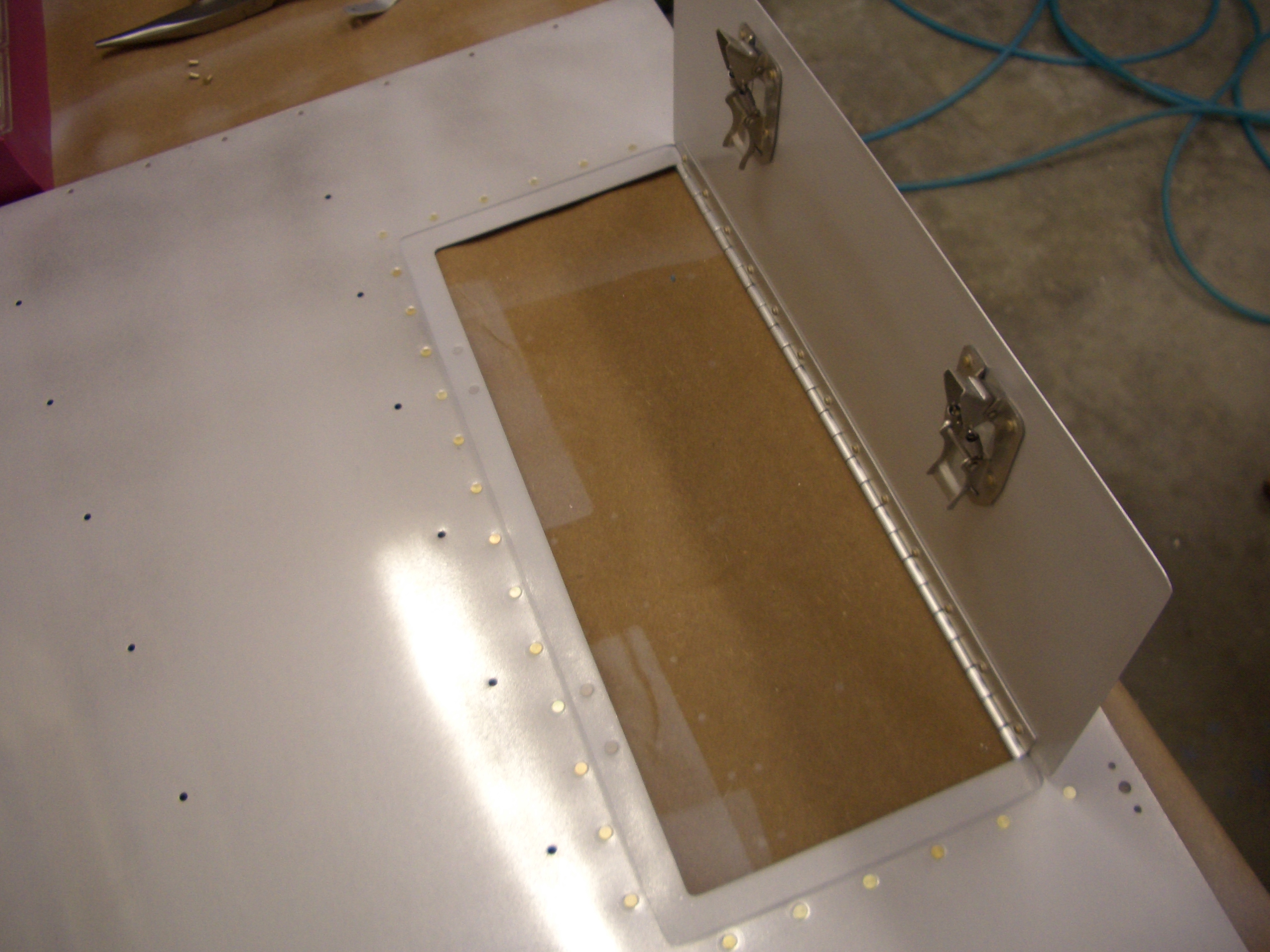
And it opens just enough past vertical that it will stay on its own.  I’m really happy with how this turned out.  This will come in very handy.

Finished Baggage Wall

I positioned and drilled the wear blocks.

Here you can see that the opening in the wear block keeps the stainless steel cable away from the aluminum.

The holes that were match drilled in the lower baggage wall need K1000-08 nutplates installed so that the upper wall can be screwed to the lower wall.

The lower wear block gets blind riveted to the lower wall with a couple of spacers made from 0.040″ AL sheet.  I didn’t take a picture, but the upper wear blocks are riveted to the upper wall in the same fashion.

Attached Seat Bottom Hinges

The seat backs attach to the seat bottoms with sections of P3 hinge material.  There are three pieces of hinge attached to the seat bottom, and one piece attached to the seat back.  That along with the adjustment mechanism at the top gives you a number of choices for the seat position.  First up, I cut eight pieces of hinge material 15.5″ long.

The six hinge pieces that attach to the seat bottom need the center two eyelets removed so that the hinge pins can be inserted from the middle.

The holes were laid out and drilled on one of the pieces according to the plans.  This was then used as a template to drill the other five pieces of hinge.

The hinges were then clamped to the seat bottoms at the position specified by the plans.

The seat bottoms were then match drilled to the hinges.

The aft hinge overlaps several holes that are used to attach the seat bottoms to the seat ribs.  The hinge is back drilled to these holes so that all three pieces can be blind riveted together.

The hinge pieces are then riveted to the seat bottom with AN470AD4-4 rivets (skipping the holes that will also rivet in conjunction with the seat ribs).  I’ve seen a few builders use LP4-3 here, but the plans only specify those for attaching the seat bottoms to the seat ribs.

Started Flaps

The next step in the plans is to fit the forward tunnel cover, but since that sits against the flap cover, I decided I wanted to install the flaps first to ensure the cover fits as well as possible.  First up, I drilled and reamed all three ends of the flap weldment to 1/4″.

The center flap bearing block needs to be notched to fit over the seat pans and cut in half so that it can be installed around the flap weldment.

Van’s published a service bulletin a number of years ago after several people had the jam nut on the flap motor rod end back out and the flap motor disconnected from the flaps.  The plans now specify that the end of the flap motor push tube needs a small hole drilled in it so that it can be safety wired around the bolt that goes through the rod end.  This is actually a pretty hokey way to fix the problem as it subjects the safety wire to repeated flexing which can fatigue it and allow it to break.  There is an alternate approach that another builder came up with described here.  This looks like a much safer approach.

Next up, I installed the flap weldment into the plane so that the center bearing block could be used as a guide to drill the floor and ribs

Here is the lower half of the center bearing after drilling.  I went ahead and drilled through the rear tunnel cover and then marked around the bearing since the tunnel cover must be notched to wrap around the bearing.

The side of the flap support need to be reinforced where the upper end of the flap motor mounts.  I match drilled this to the channel and reamed the center hole out to 1/4″.

Next, I fabricated this little bracket which holes the other end of the flap motor mount bolt.

Installed Flaps Temporarily

The aft flap cover needs a bracket fabricated to attach it to the floor.

The top of the front flap cover needs this little bracket fabricated to tie the cover to the F-705 upper channel.  I’m really glad I have a bending brake; it made bending this just trivial.

The lower end of the front cover needs this attach points riveted.

The front cover also needs a series of nutplates installed down both sides.  These will be used to attach the flap side covers.

I primed and riveted the upper motor mount reinforcing plate to the forward flap cover channel.

I also riveted the lower attach bracket to the aft cover channel.

Here is the plate that I bent on the bending brake earlier.  It’s riveted to forward flap cover and gets a couple of one-leg nutplates for attaching it to the upper F-705 channel.

I installed the forward flap channel into the plane and temporarily bolted the flap motor push rod to the weldment.  I couldn’t help running the motor up and down a bit to watch it work.

After ensuring the inner bolt support was properly aligned, I match drilled it to the channel.  It’s almost 2 a.m., so this is a good stopping point.

Finished Flap Fabrication and Drilled for Com Antenna

After fitting and drilling the rear flap cover, I fit and drilled the side covers.  This totally encloses the flap motor assembly since the seats fit right up against this.

The rear flap cover gets a bunch of nutplates that are used to attach it to the F-705 upper channel and to attach the side covers to it.

After removing everything back down to the ribs, I vacuumed out the shavings and installed some adhesive zip-tie mounts.  I then used zip-ties to support the conduit between the bulkheads.  I finally got a chance to try the zip-tie gun I picked up from Harbor Freight last year.  This thing is great; it automatically tightens the zip-tie to a consistent tension (which is adjustable) and then cuts it off flush so that there is no sharp point sticking out to scratch you.

I also installed some adhesive mounts along the conduit aft of F-706 and trimmed off the front a bit.

Before installing the seat pans, I need to take care of a couple of final things that will be more difficult with them in place.  I’m installing the primary com antenna under the pilot’s seat, one bay outboard of the center bay with the crotch strap.  I drew a centerline on the floor in the bay and then positioned the template far enough aft that the coax can’t interfere with the aileron push tube.

I drilled the holes out to the specified size.

Here is what the antenna will look like installed.  This bay is very narrow, and the antenna mounts with a doubler plate, so I’m not going to add any additional reinforcement.

Fit Forward Baggage Side Covers

I fit the forward baggage side covers, then removed them to install nutplates on the bottom flange,  The baggage floor will screw down to this flange,

Here you can see how the side cover fits.  The bottom flange fits under the baggage floor and the other three side screw down to side bulkheads.  The flap torque tube will stay exposed in the plane, but it rotates in place, so nothing can catch on it.

Now that everything has been match drilled, the nutplates on the aft side covers can be installed.

I got an order from SteinAir the other day which included a bunch of wire I’ll need to start wiring components in the plane.  I ordered about 30′ of RG-400 which is enough to do most if not all of the antennas in the aircraft.  I also purchased an adjustable RG-59 three blade coax stripper off eBay.  After a bunch of test cuts, I managed to get the stripper adjusted for RG-400 so that it perfectly cuts all of the various component of the cable without nicking any wires.  I then installed a male BNC connector on the end to test the crimper I bought.

The crimper I have has interchangeable dies.  I installed the hex dies and crimped the gold plated center pin to the stranded center conductor with the 0.068″ die (RG-58 and RG-400 both have stranded center conductors for use in the high vibration environment of an aircraft compared with the solid center conductor of RG-59 that is typically used in home cable tv systems.  It’s also 50? instead of 75? impedence).  Next, the connector body is pushed onto the pin until it clicks into place.  Finally, the ferrule is slide up tight against the connector body and crimped with the 0.213″ die.