I fabricated the 0.020″ spacers for the hinges that attach the bottom of the cowl to the firewall.
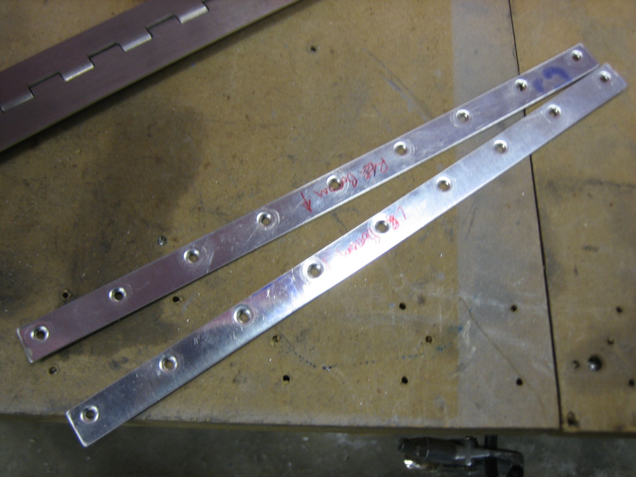

I fabricated the 0.020″ spacers for the hinges that attach the bottom of the cowl to the firewall.
I got an email from Joe Blank at Van’s today. After reviewing my cowl fitting issue further, they now think my cowl is made correctly and that if I trim the aft edge all the way around, I should have enough overlap on the sides to make a straight joint.
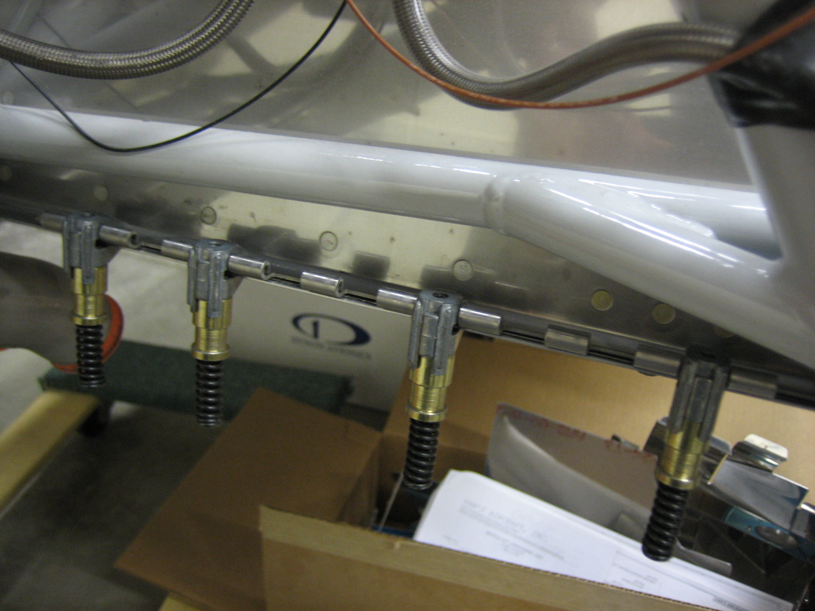
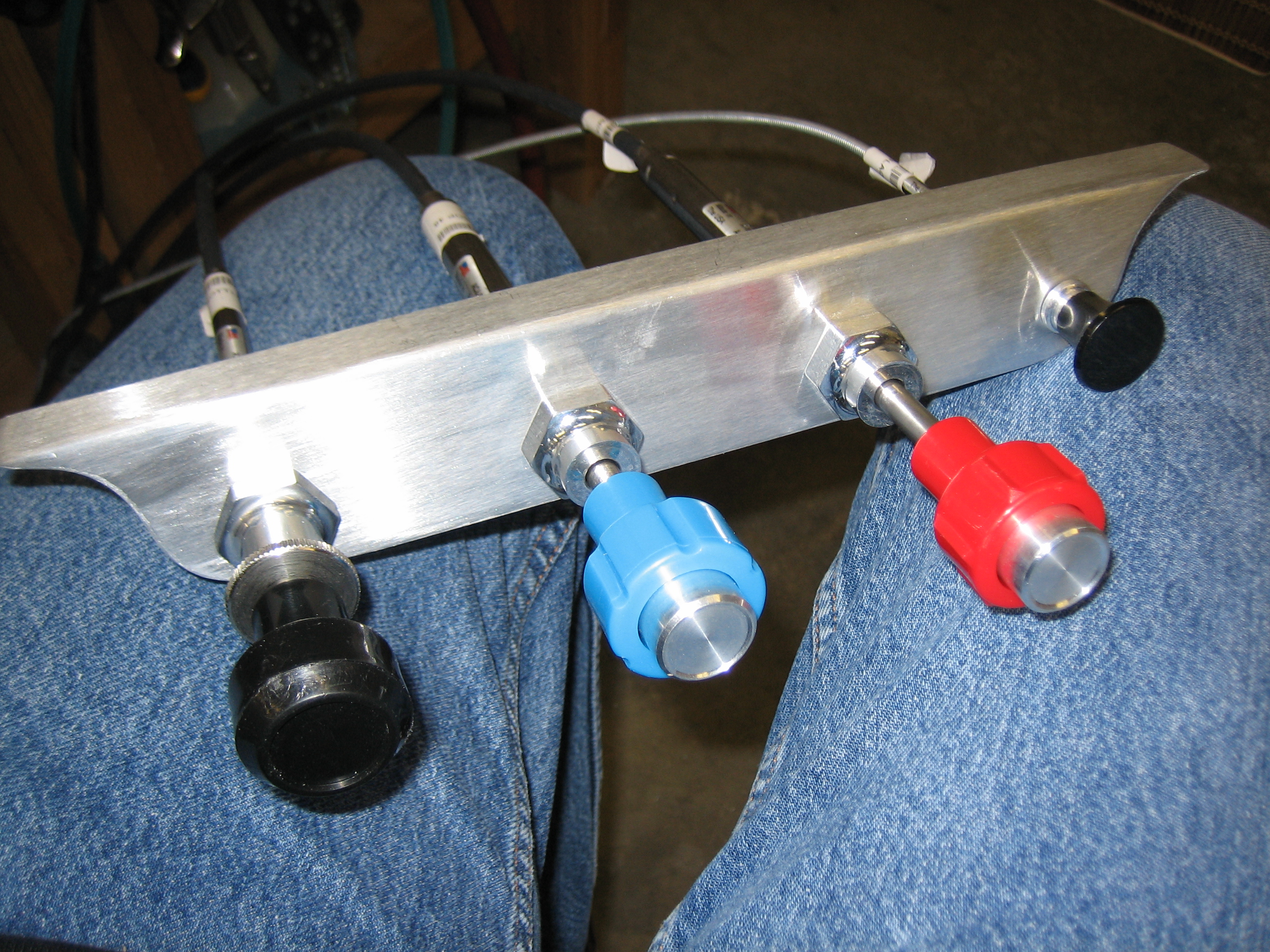
Anyway, tonight’s little project was to determine the mounting position for the control cables. I used the stock bracket that came with the kit to mock up a potential control spacing to see if there were any conflicts before drilling the actual bracket that I bought from Experimental Air. My original goal (and what I mocked up here) was to put the three engine controls in the center, the parking brake on the left and the cabin heat on the right. This resulted in 2″ between the outer knobs and the outboard engine controls and about 2 7/16″ between each of the engine controls. After playing with it for a few minutes, I decided that this was too tight and that the cabin heat knob should be removed from the bracket.
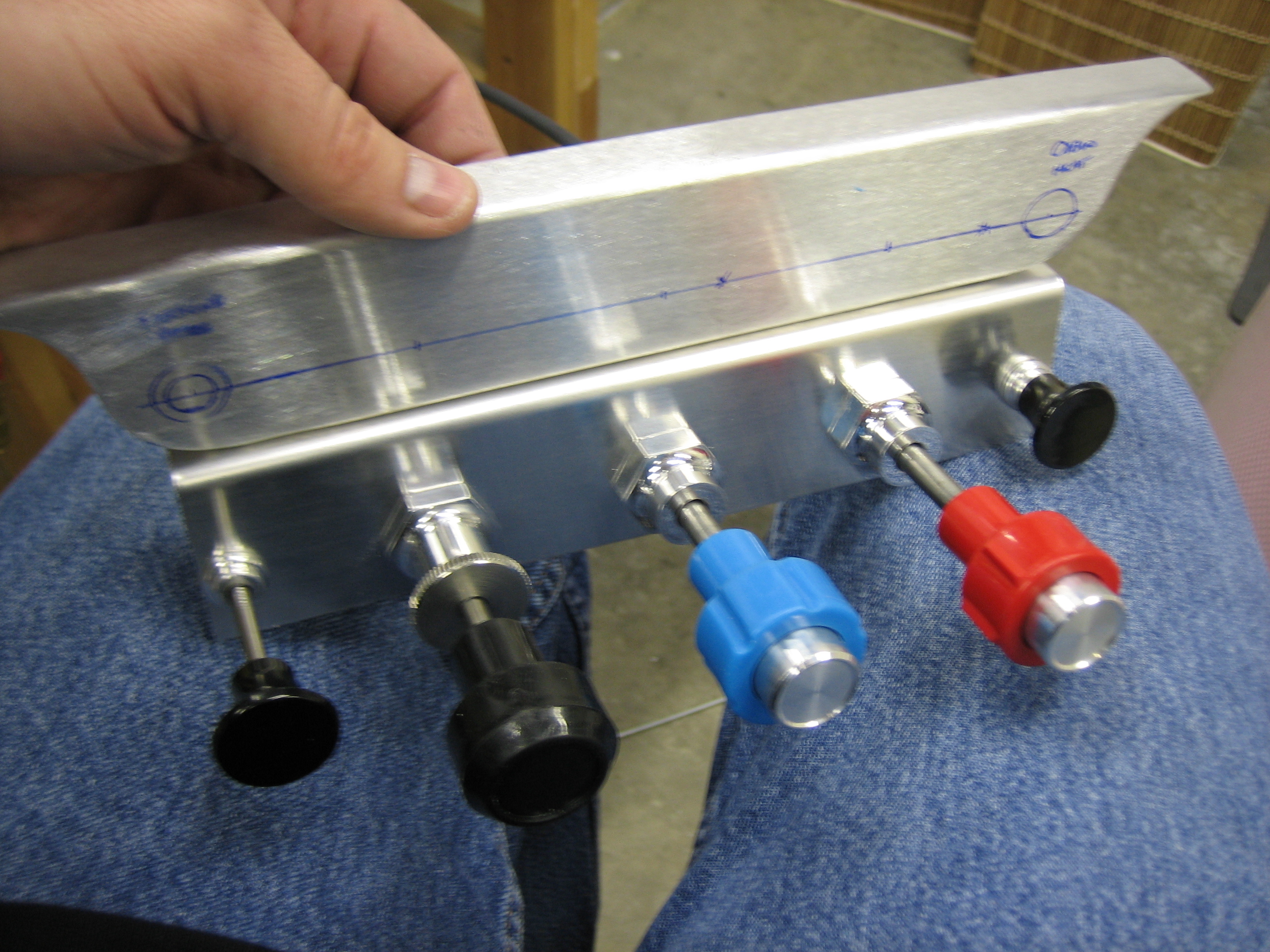
As you can see, I also moved the parking brake knob over to the right side of the bracket so that it’s out of the way. This also has the advantage of bringing the engine controls closer to me. The three engine controls are spaced 3″ apart and the parking brake knob is a hair over 2 1/2″ from the mixture knob. You can also see that I drilled the holes lower than the center of the bracket. They’re 3/4″ up from the bottom edge which leaves plenty of room to provide labels for each of the controls.
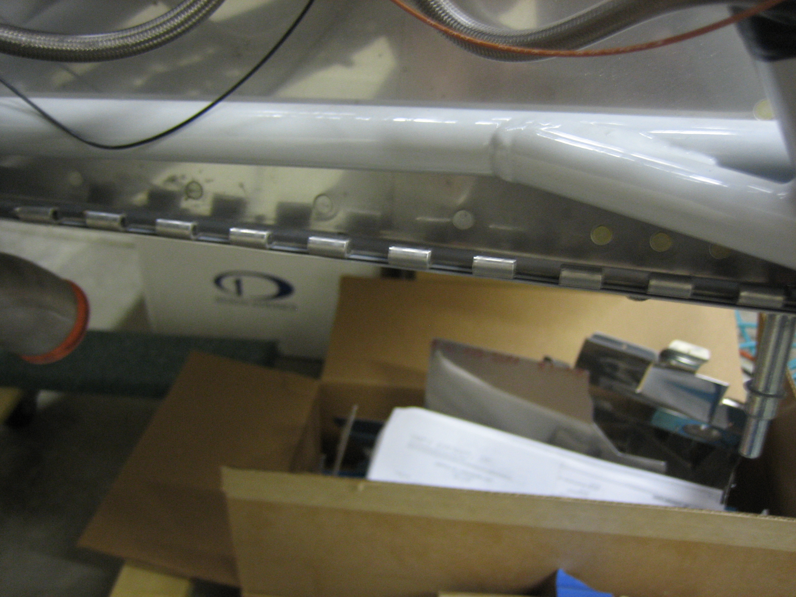
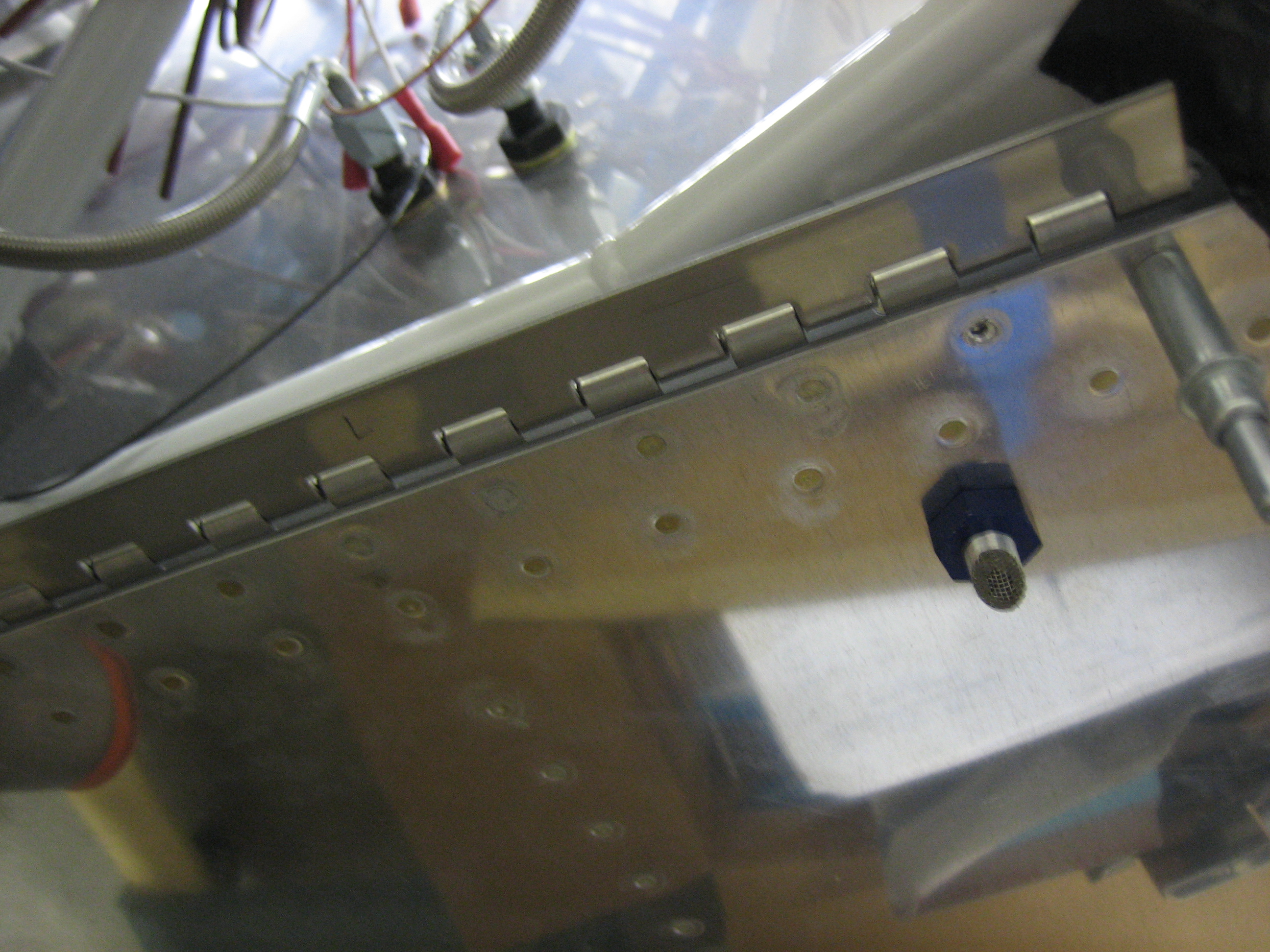
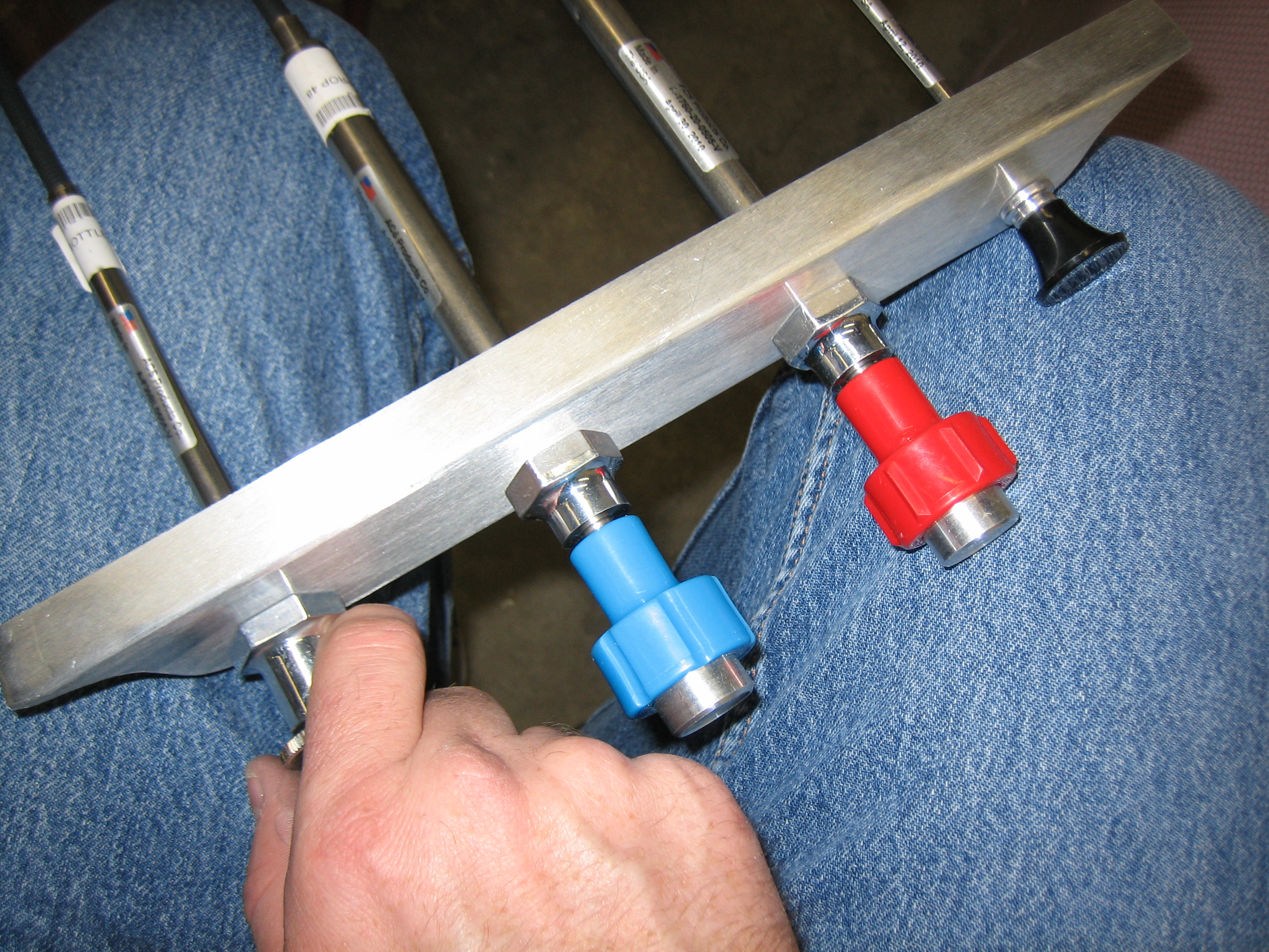
A top view shows that my hand has plenty of room when operating each knob.
I got an order from Aircraft Spruce today with some shielded 22AWG wire. I soldered the inner wire to pin 6 of the lightspeed input connector and the shield to pin 13. I then slipped inner and outer pieces of heat shrink over the wires and shrunk everything in place.
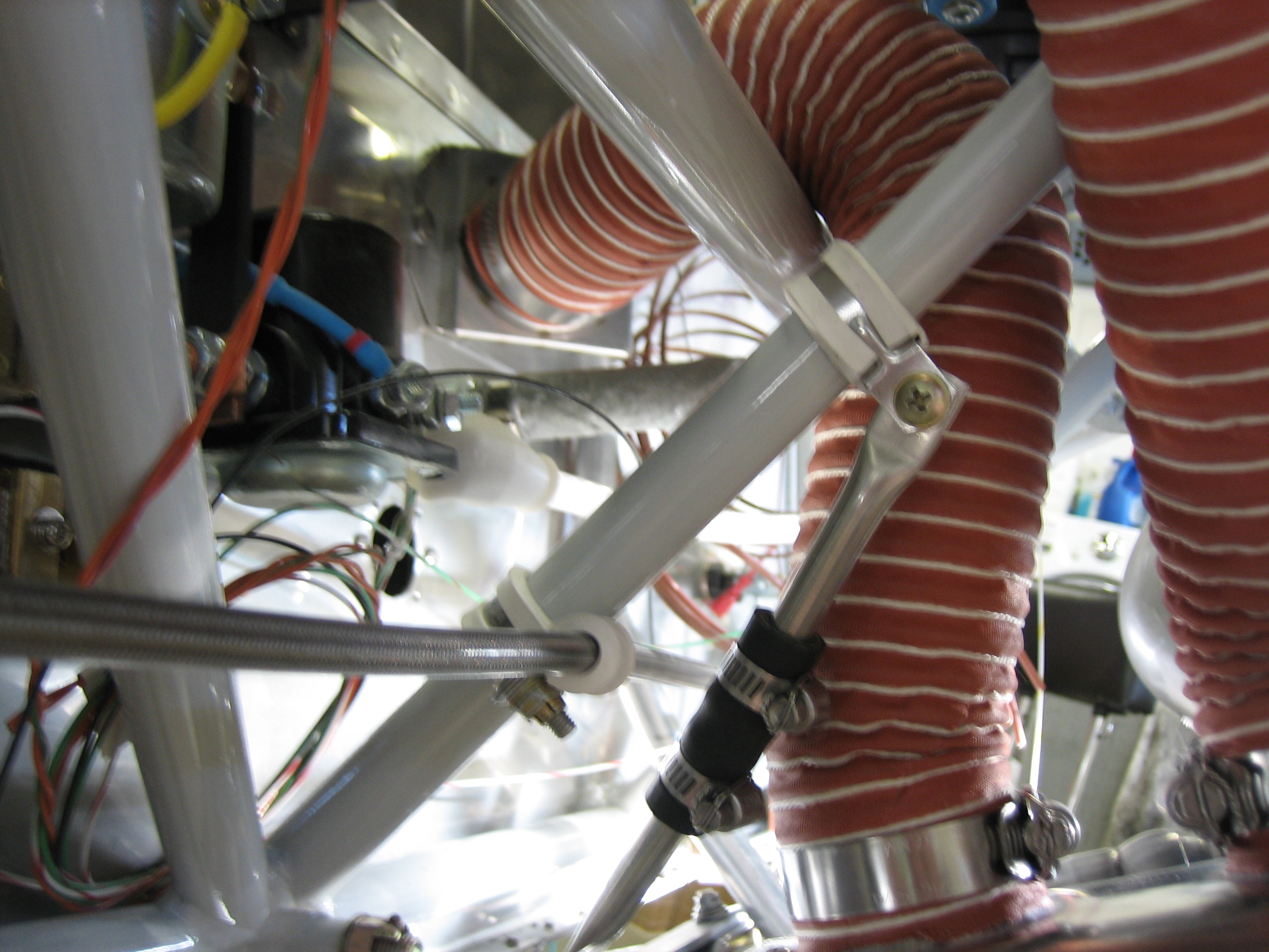
Also in the order was some 2″ scat tube and some 2″ hose clamps. Here is the hose from the output of the heat muff up to the heat box on the firewall.
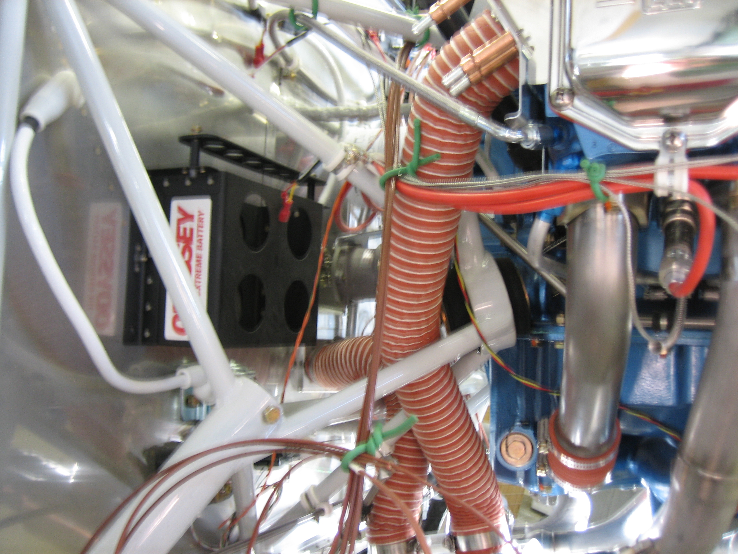
Here is the hose from the back of the baffles down to the heat muff. I’m not sure if I need to secure this at an intermediate point or not; I need to do a little research on that.
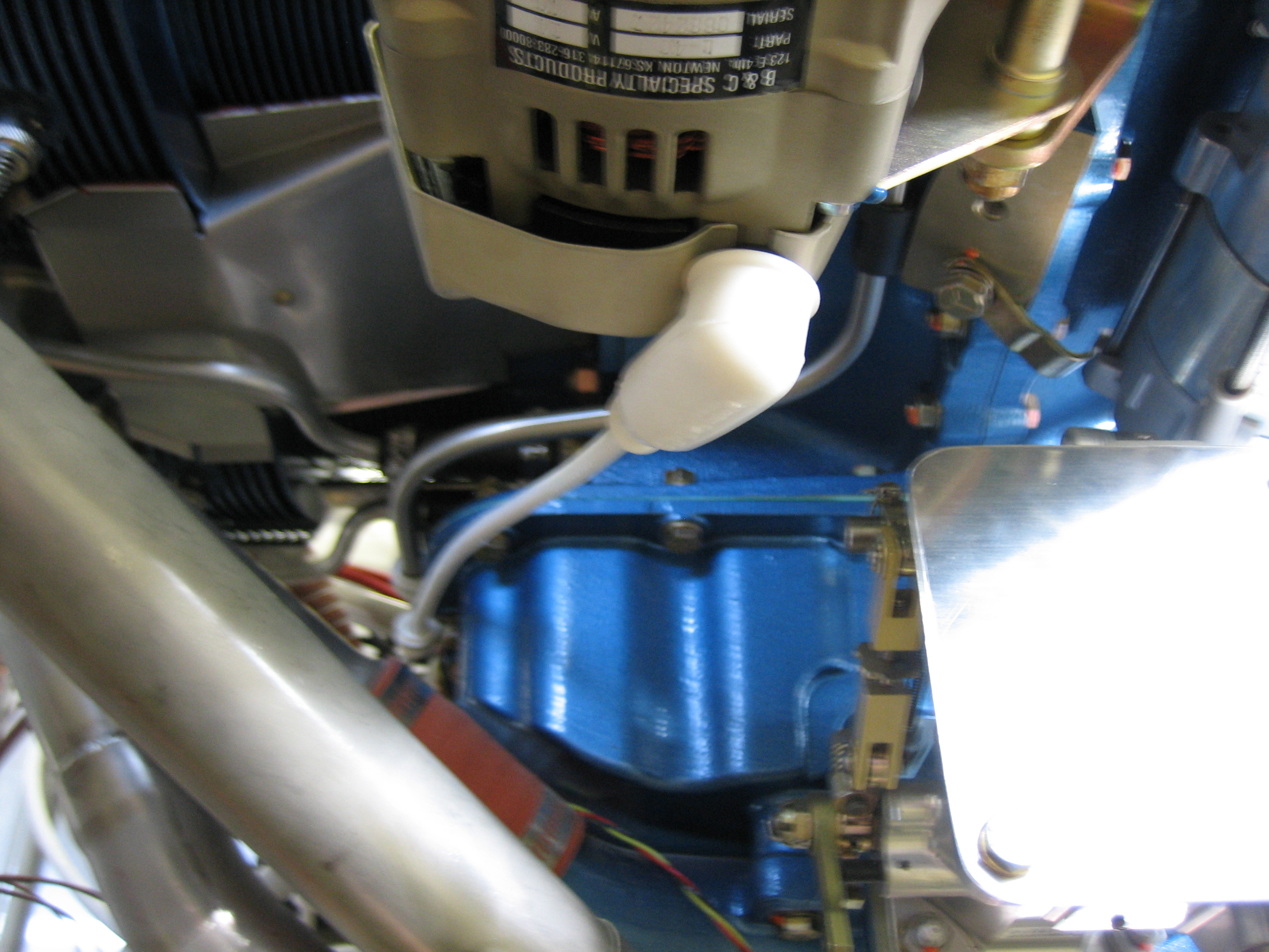
I installed the alternator wire today. This is 6AWG wire which is slightly larger than what is needed for a 40A alternator (8AWG would be fine), but there’s a possibility I may swap this out for a 60A alternator at some point, so I went ahead and ran 6AWG. Here’s the connection at the alternator end. A terminal has been crimped on, then heat shrink over that to act as a strain relief, then a boot over that to keep the hot lead protected.
I anchored the wire to one of the sump bolts where there was already a longer bolt for the prop line.
Here you can see that the line is anchored in two more places before connecting to the shunt.
After finishing up the alternator cable, I resumed work on the canopy side skirts. I pulled the canopy and frame off of the plane and drilled the #27 holes for the #6 screws, then deburred, dimpled, and countersunk all the necessary holes.
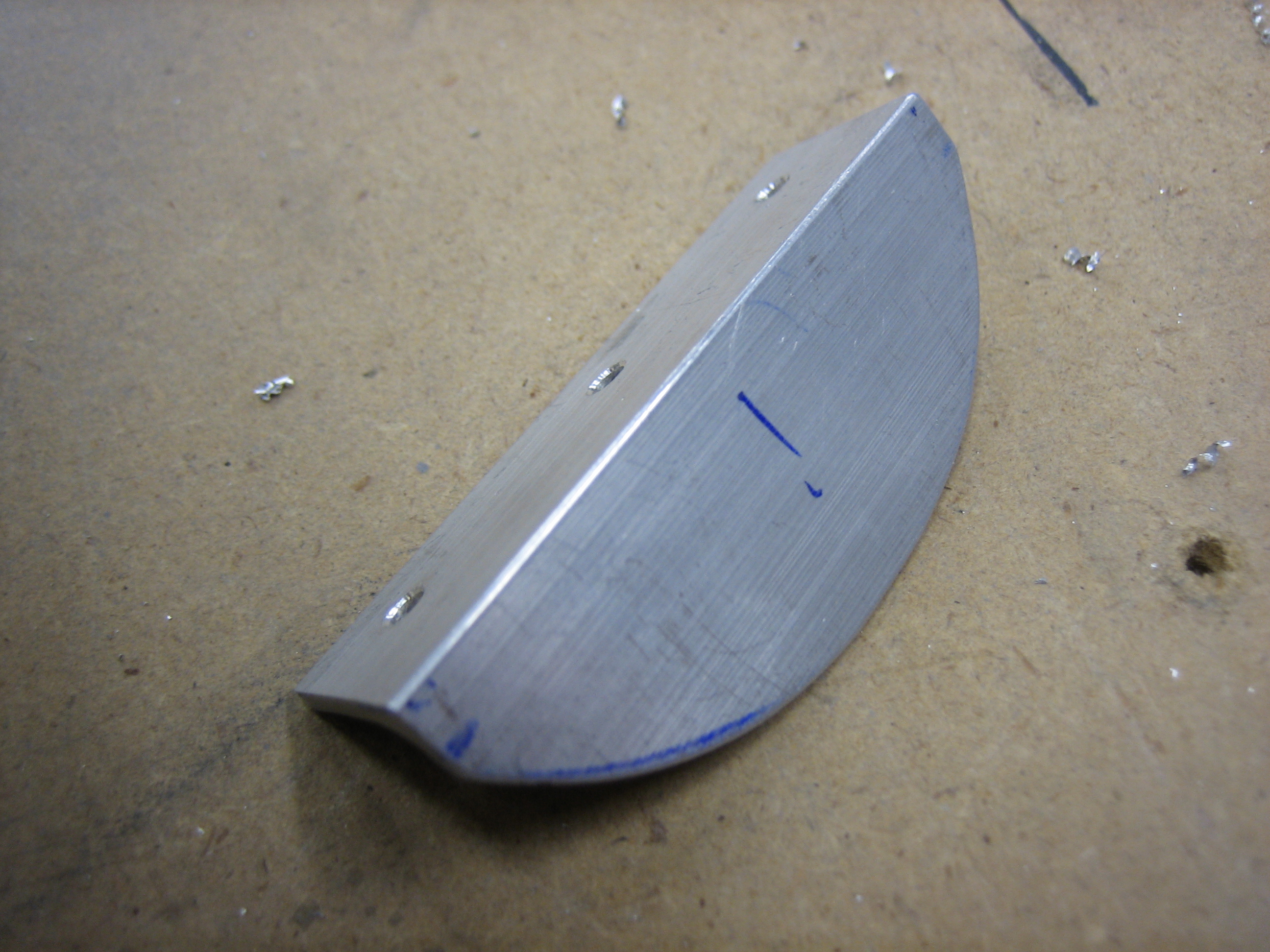
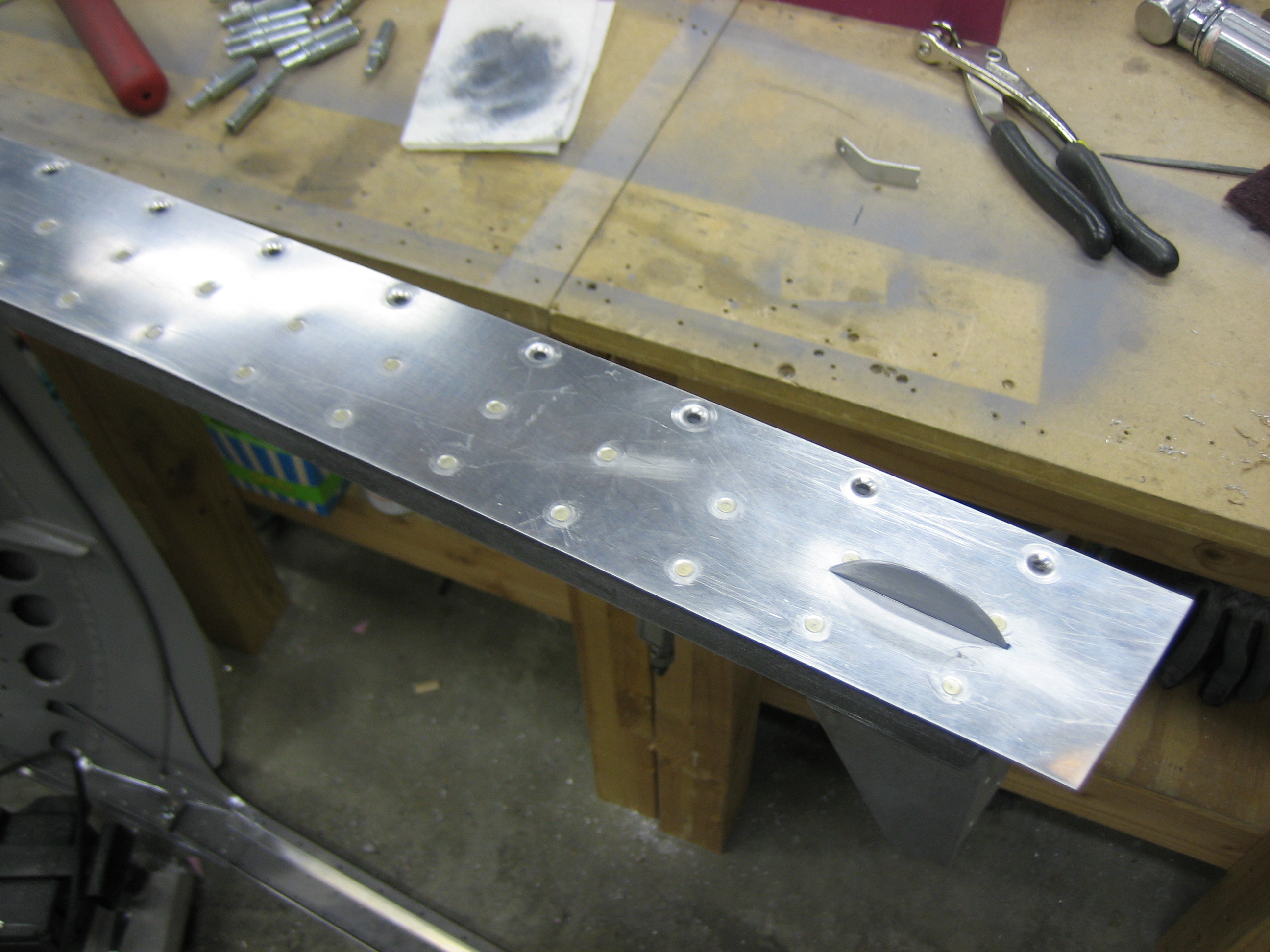
The plans have you fabricate a boring, angular canopy lift handle and then rivet it to the outside of the canopy frame. I thought it looked cheesy, so I’m deviating a bit here. First up is to round the handle nicely instead of just chopping the corners off.
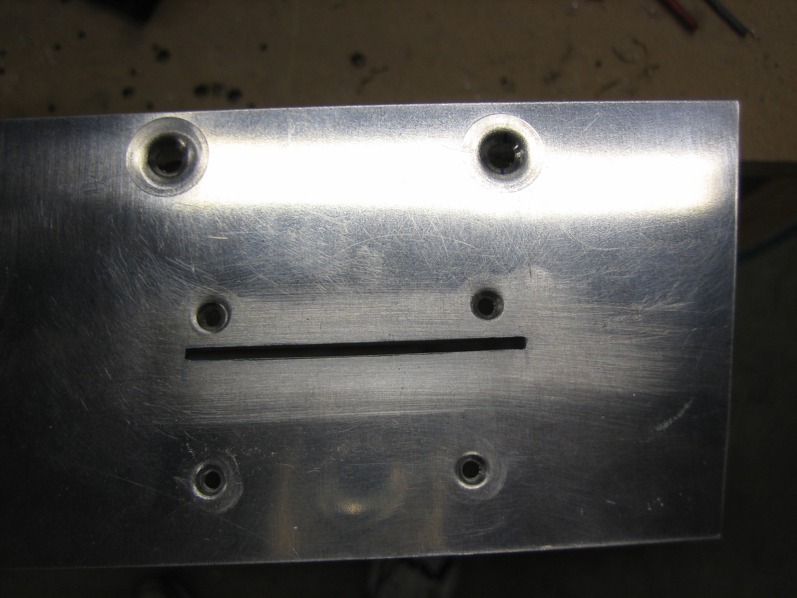
I then cut a slot in the canopy skirt and frame. This will allow me to mount the handle on the inside and only have the horizontal piece be seen from the outside. I made the initial slot with the cutoff wheel in the die grinder and then used needle files to get it perfect.
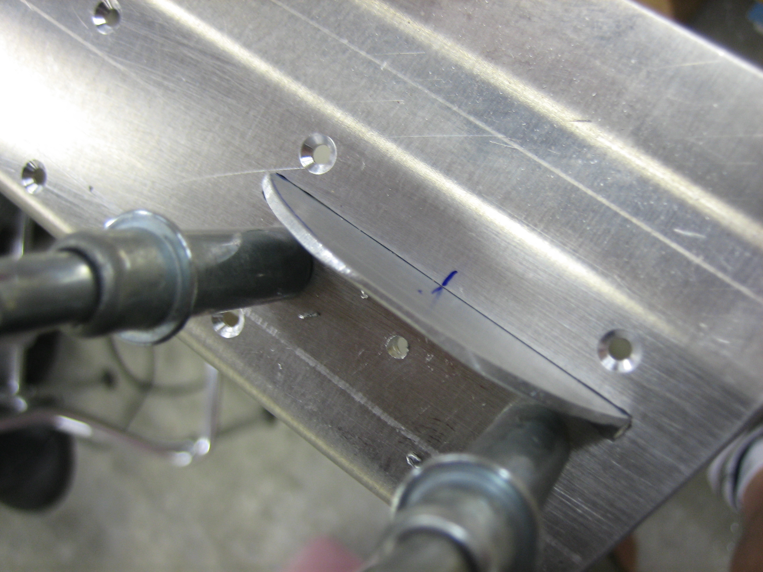
I then clamped the handle to the inside of the canopy frame only.
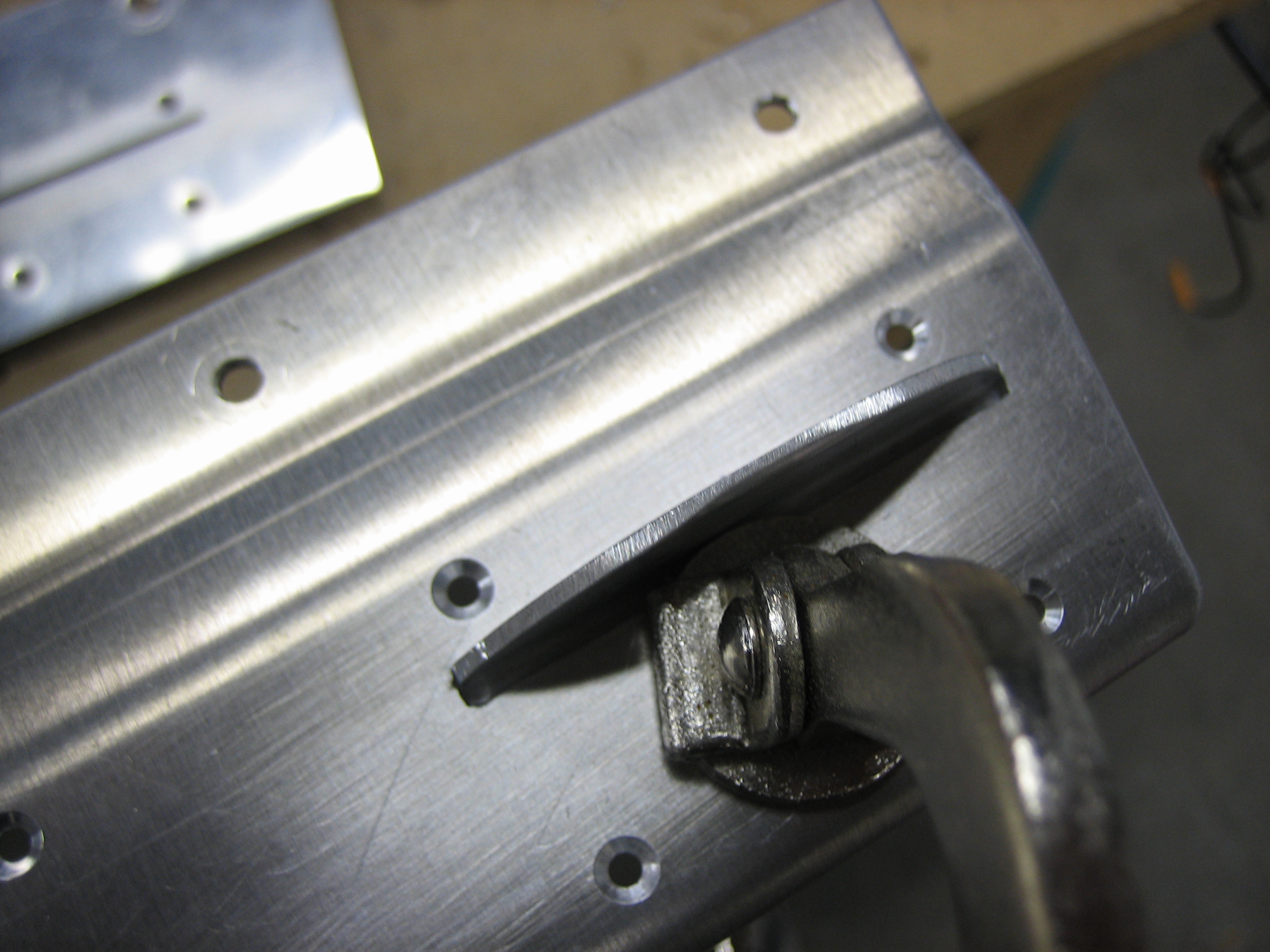
And drilled the frame to the handle.
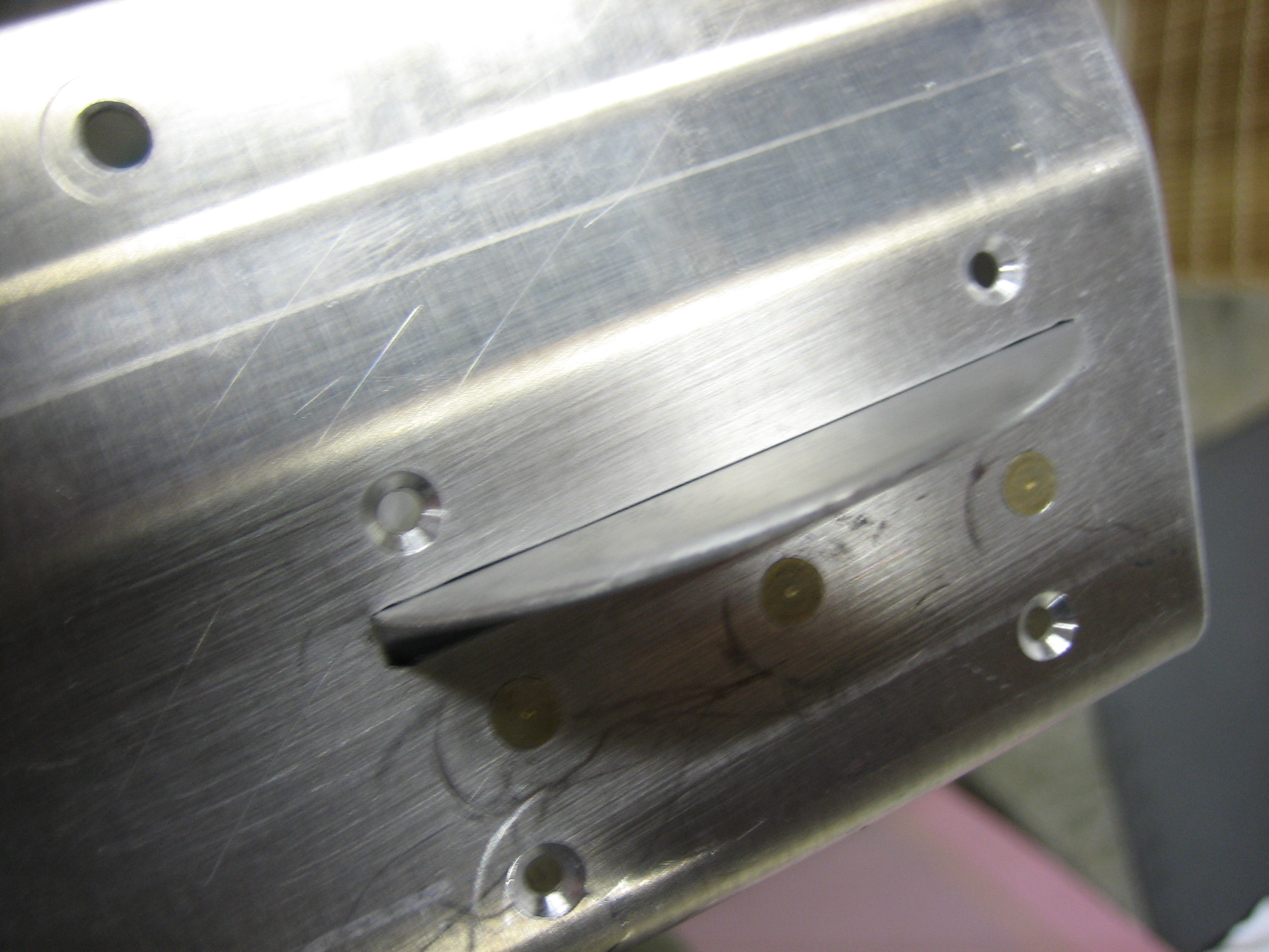
After deburring, countersinking, and priming the mating surfaces, I riveted the handle to the frame only.
Finally, I installed the skirt and riveted it to the frame. This looks so much nicer than the handle specified in the plans and only took about an hour to do. While I was working on the side skirts, I rewatched (mostly just listened to) Evil Dead III: Army of Darkness for about the 20th time. That is such a fucking awesome movie; Bruce Campbell rocks.
I zip-tied the EGT and CHT wires to the ignition wires on both sides. These are just temporary, but I need to get the wires in their final positions so that I can begin cutting things to length.
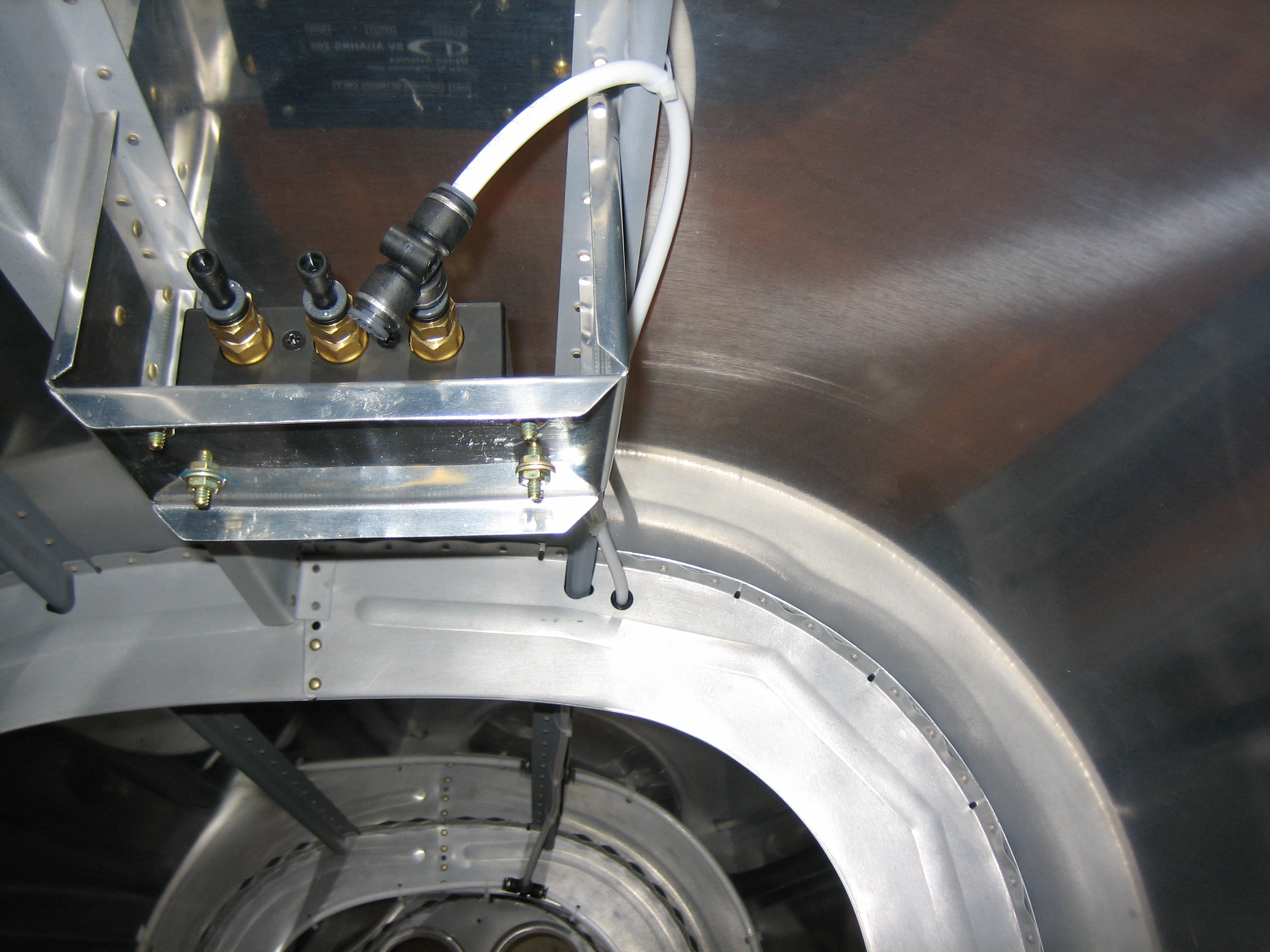
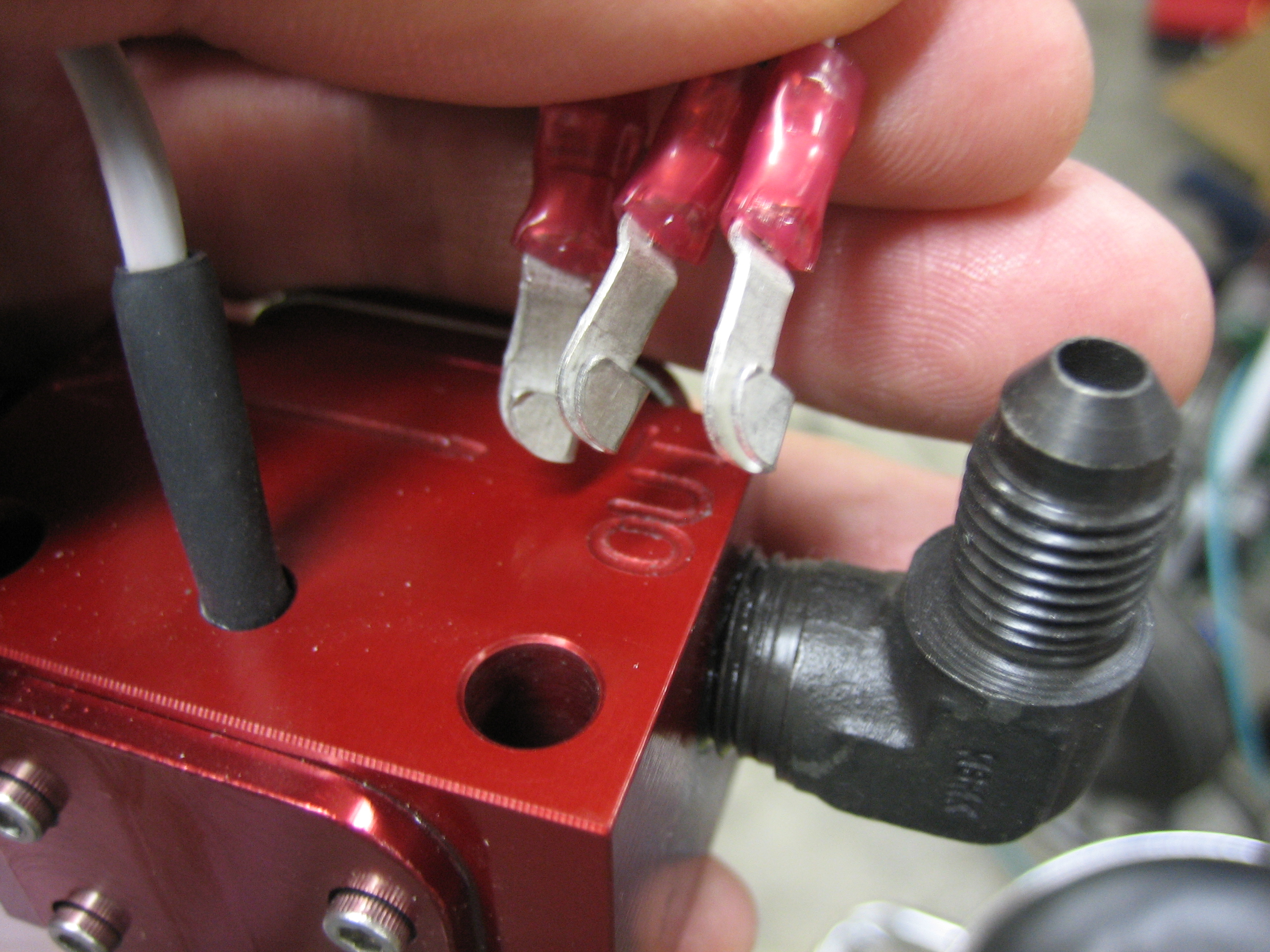
I then installed the 1/4″ nipples into the EI FT-60 (colloquially known as the “red cube”). This will be mounted between the fuel injection servo and the spider and will measure the fuel that’s being delivered to the engine.
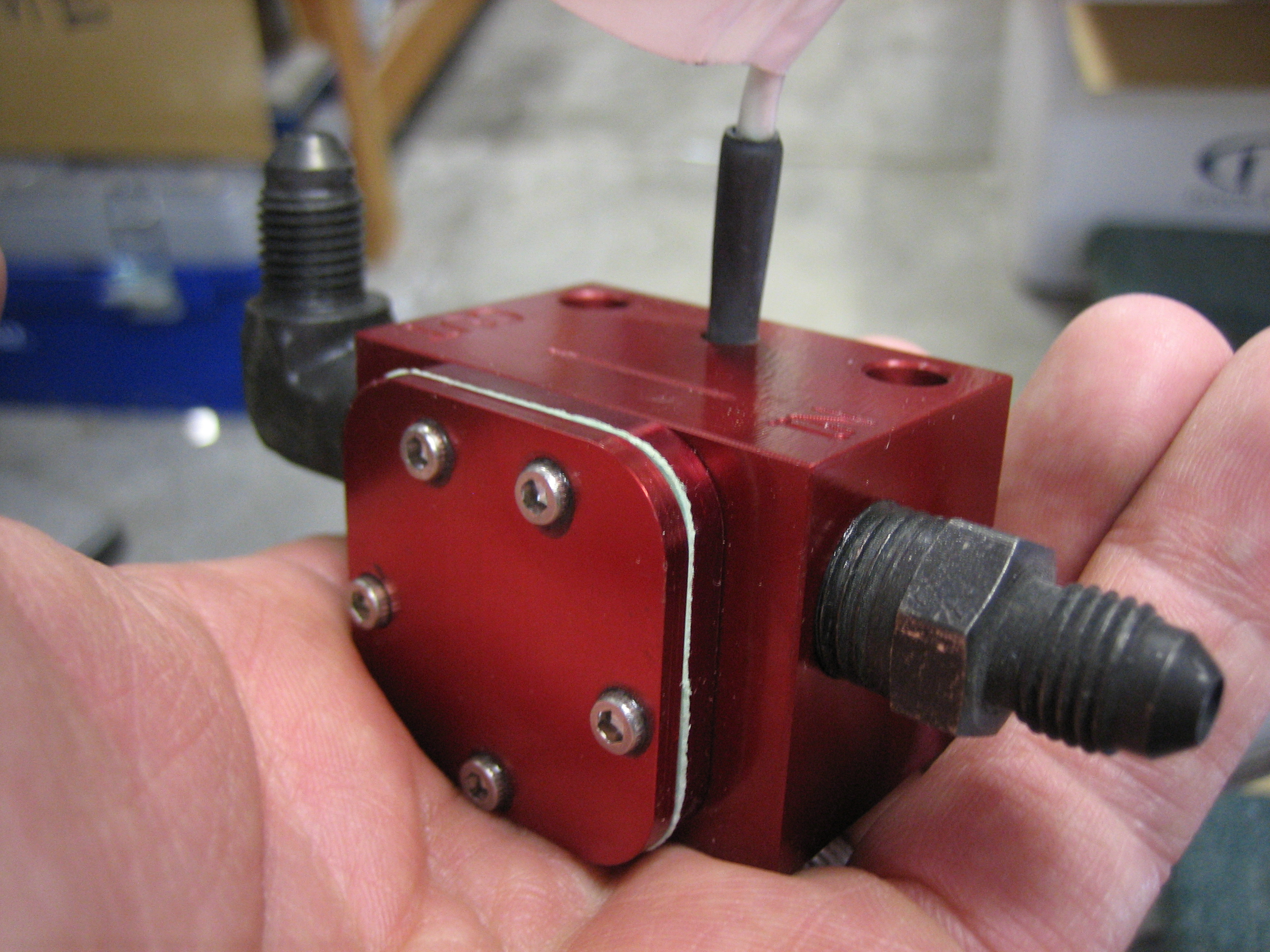
Here’s roughly where it will be installed. I will need a 2 3/4″ hose that connects the fuel servo to the input side of the red cube. Hopefully Bonaco can make one this short.

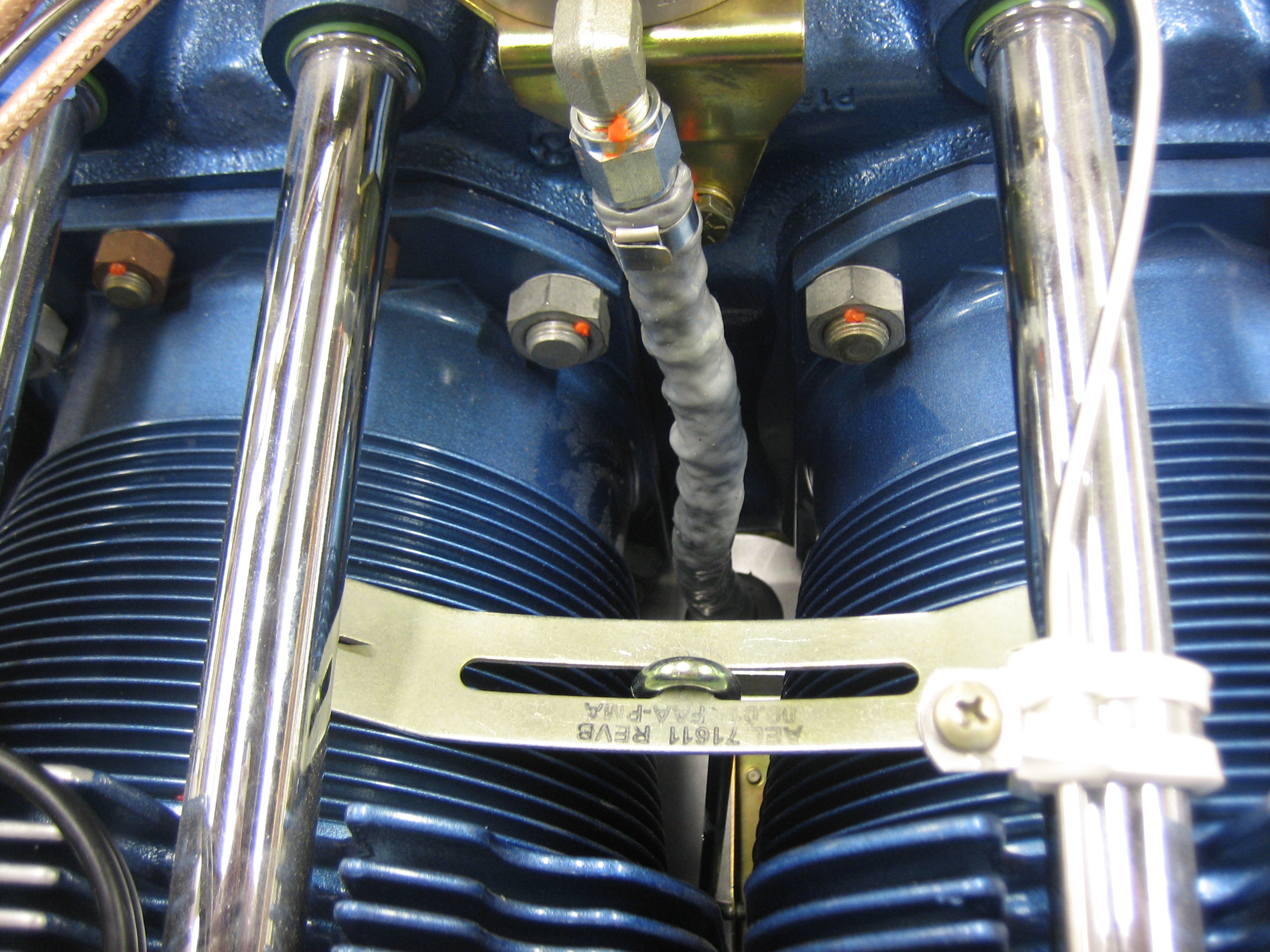
The output side of the cube has a 90º elbow that points directly at the inner end of the right-side inter-cylinder baffle. I’ll drill a hole through there to pass the hose that connects the red cube to the spider.

I also removed, re-lubed, and reinstalled the fitting in the spider so that it points straight down. The shiny area between the cylinders is the inner cylinder baffle where the hole will be drilled.

I removed the right side inter-cylinder baffle so that I could drill the hole.

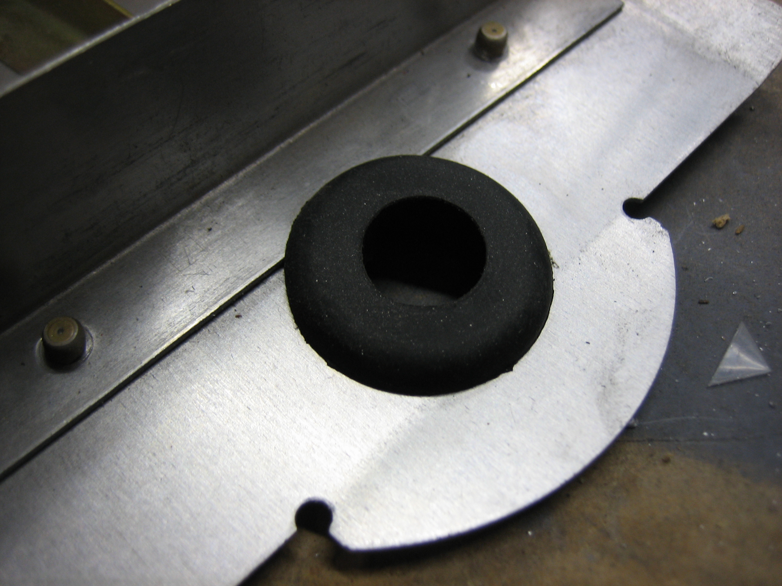
I drilled a 13/16″ hole…
…that will hold a grommet that has a 1/2″ interior hole. That is roughly the outside diameter of a 1/4″ hose with firesleeve. I’ll have to install the grommet over the hose before installing it in the hole, but I wanted to make sure it fits properly.
I stopped by OSH and picked up some #10 brass hardware and installed the SkyView ADAHRS. The ADAHRS contains a magnetometer, so there can’t be any ferrous metal near it so that it can get an accurate heading reference.

I crawled back in the tailcone (hopefully for the last time) to install the static tubing from the tee on F-708 (near the bottom of the picture) through F-707 and into the front of the ADAHRS. There is a tee installed here because the static line will also run forward to the TruTrak Gemini that I’m using as a backup EFIS.
One of the things I got in my last order from B&C is the alternator field connector. I installed a jumper between the terminals and added some heat shrink.
I added a couple of extra pieces to build up the thickness of the single wire.

Then installed a larger piece of heat shrink over the whole thing.

Here’s where it connects to the back of the alternator.
The wire will likely run along the alternator b lead along with the wires for the fuel flow sensor.

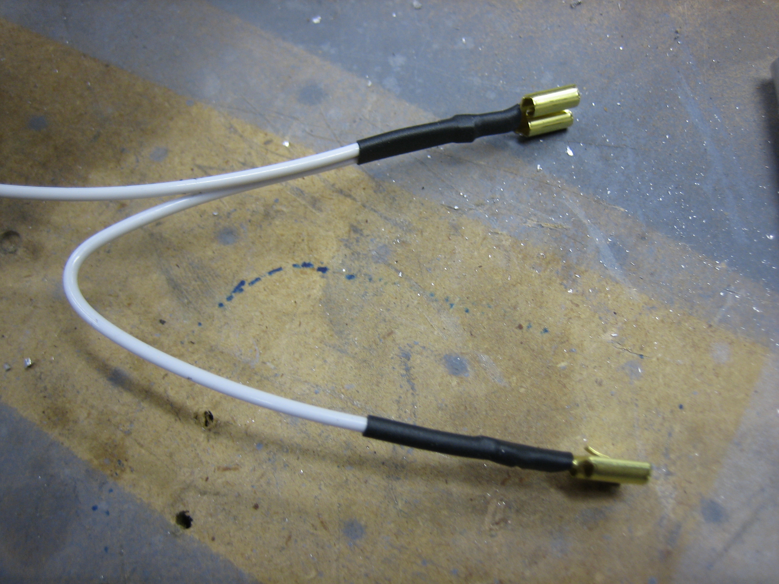
I removed the fast-on tabs from the wires on the fuel flow sensor and installed some knife connectors.
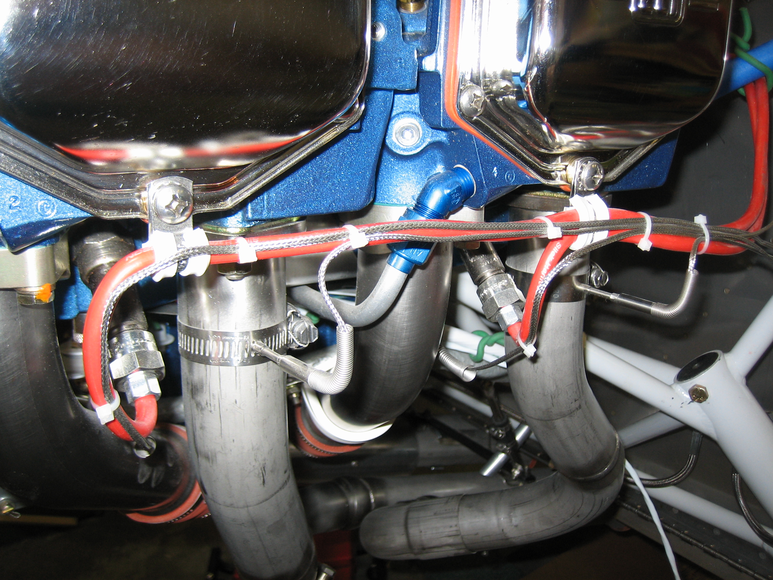
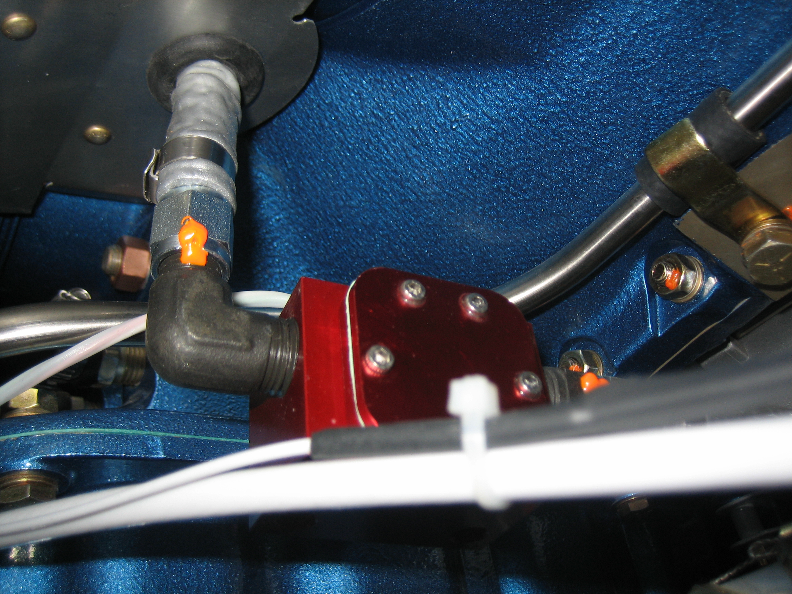
I then installed the short fuel line between the fuel servo and the fuel flow sensor. If you want to duplicate my setup, you’ll need a 2.75″ seat-to-seat hose with 1/4″ straight-to-straight connectors and firesleeve.
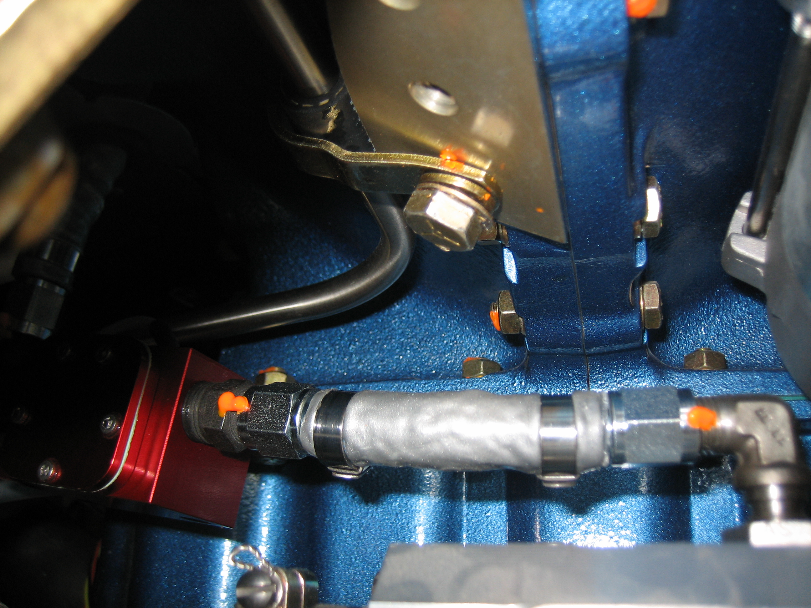
The output side of the sensor has an identical fuel line, but 9.75″ seat-to-seat. It’s a little hard to tell from this picture, but there’s quite a lot of clearance all around the sensor. It’s only about 3″ from the #1 exhaust pipe though. The alternator wire is a little closer even. I’ll put a long heat shield along this section of the exhaust pipe to reduce radiated heat to these components.
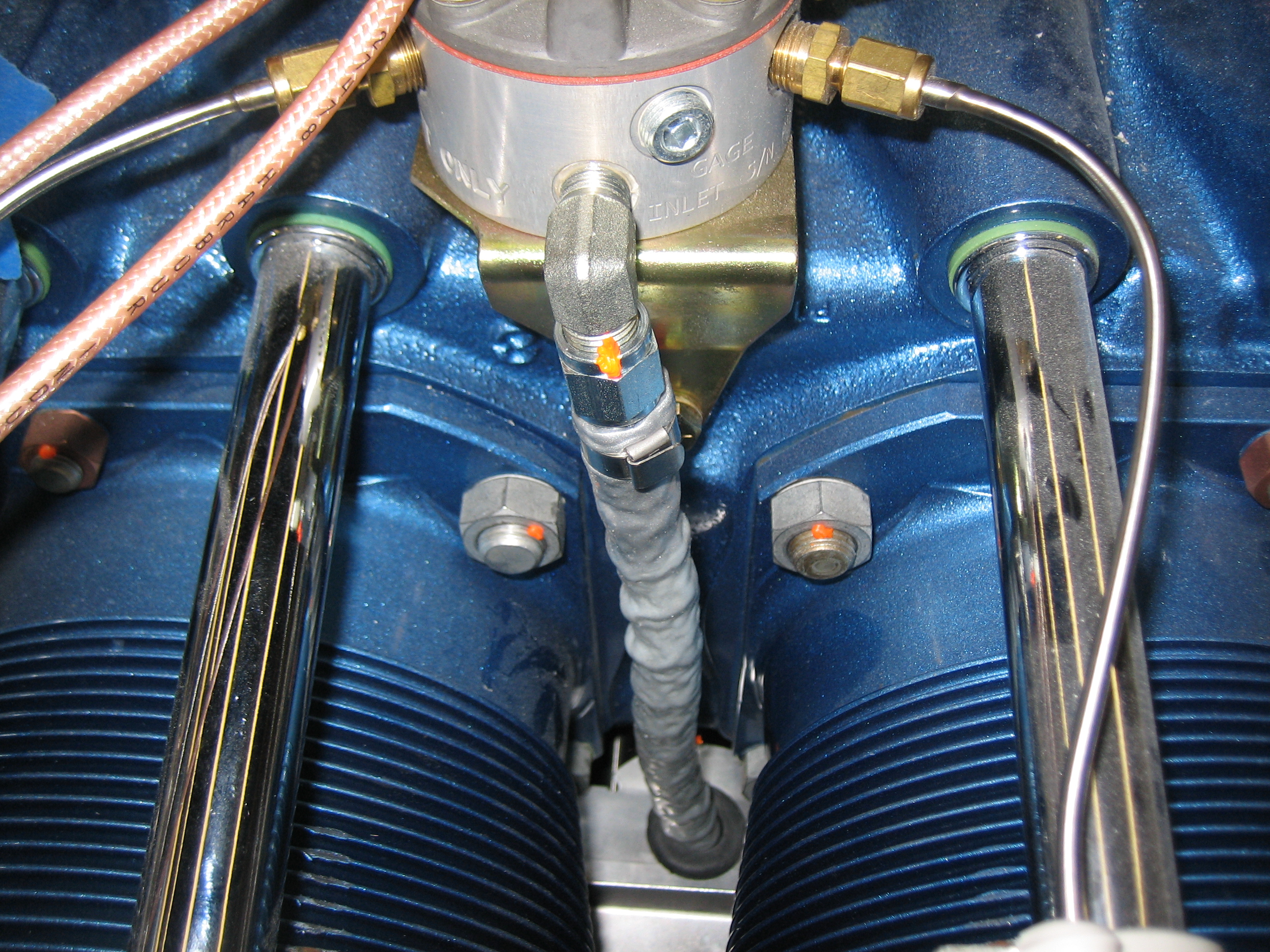
Here you can see how the fuel hose makes a straight run up to the spider from there.
I then reinstalled the inter-cylinder baffle retaining clamp (which was a pain in the ass).
I’m also using the knife connectors to connect the EGT/CHT wires to the EMS harness. I got through part of the connectors on the right side tonight.
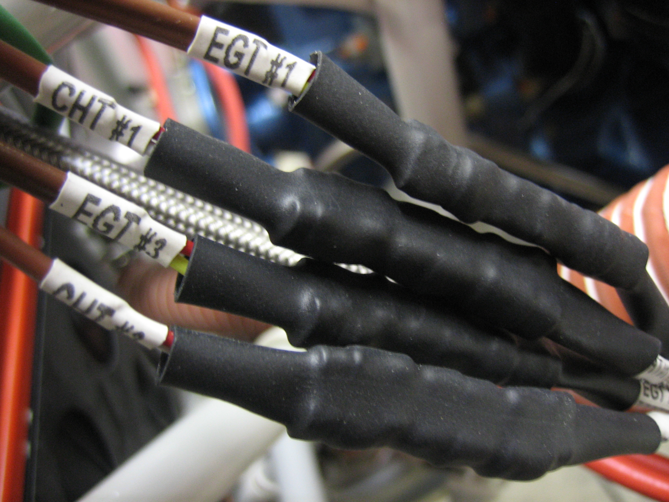
Here’s a closeup of the #1 and #3 EGT connections.
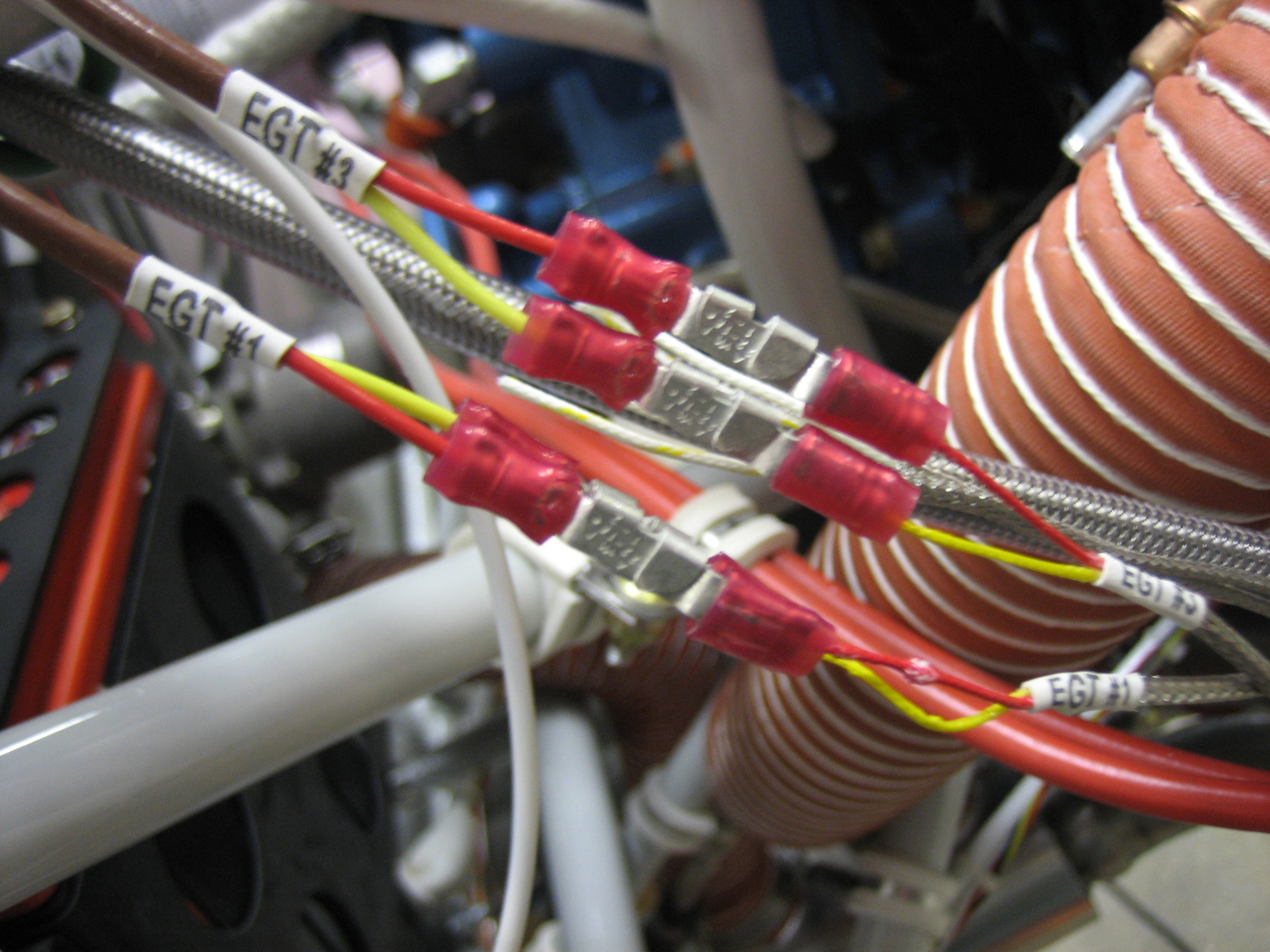
The knife connectors interlock and form a connection that can’t vibrate apart even under tension. I’ll put sections of heat shrink over all of these connections before finishing off the wiring bundle.
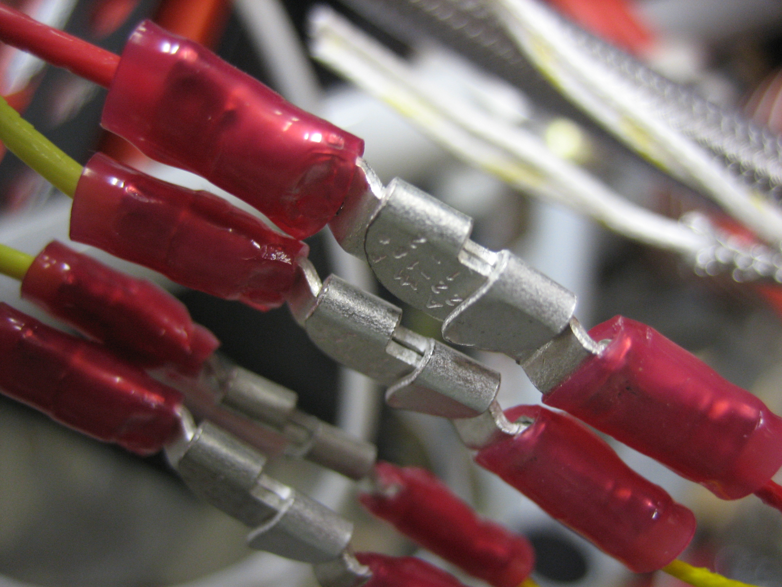
Since the knife splices aren’t insulated where they connect, I slipped a piece of heat shrink over each connection.
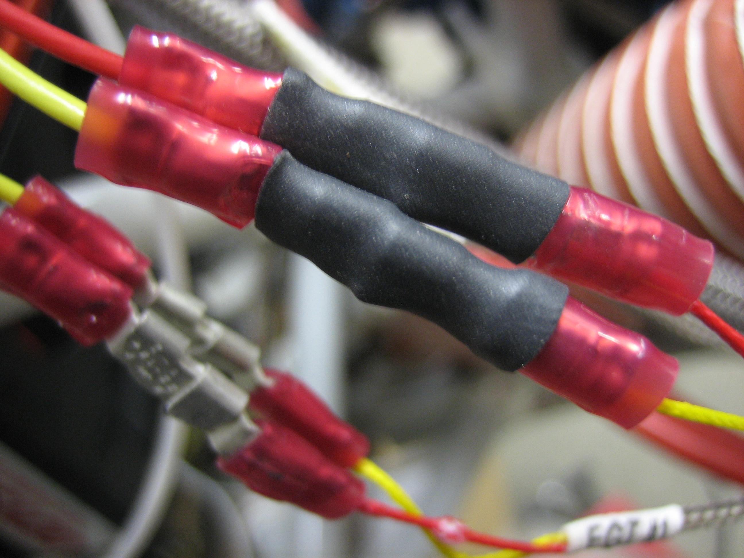
I then put larger pieces of heat shrink over each pair to keep everything immobilized. For some reason, the EGT probe wires are solid conductors instead of stranded like every other wire used on aircraft, so they need to be well supported.
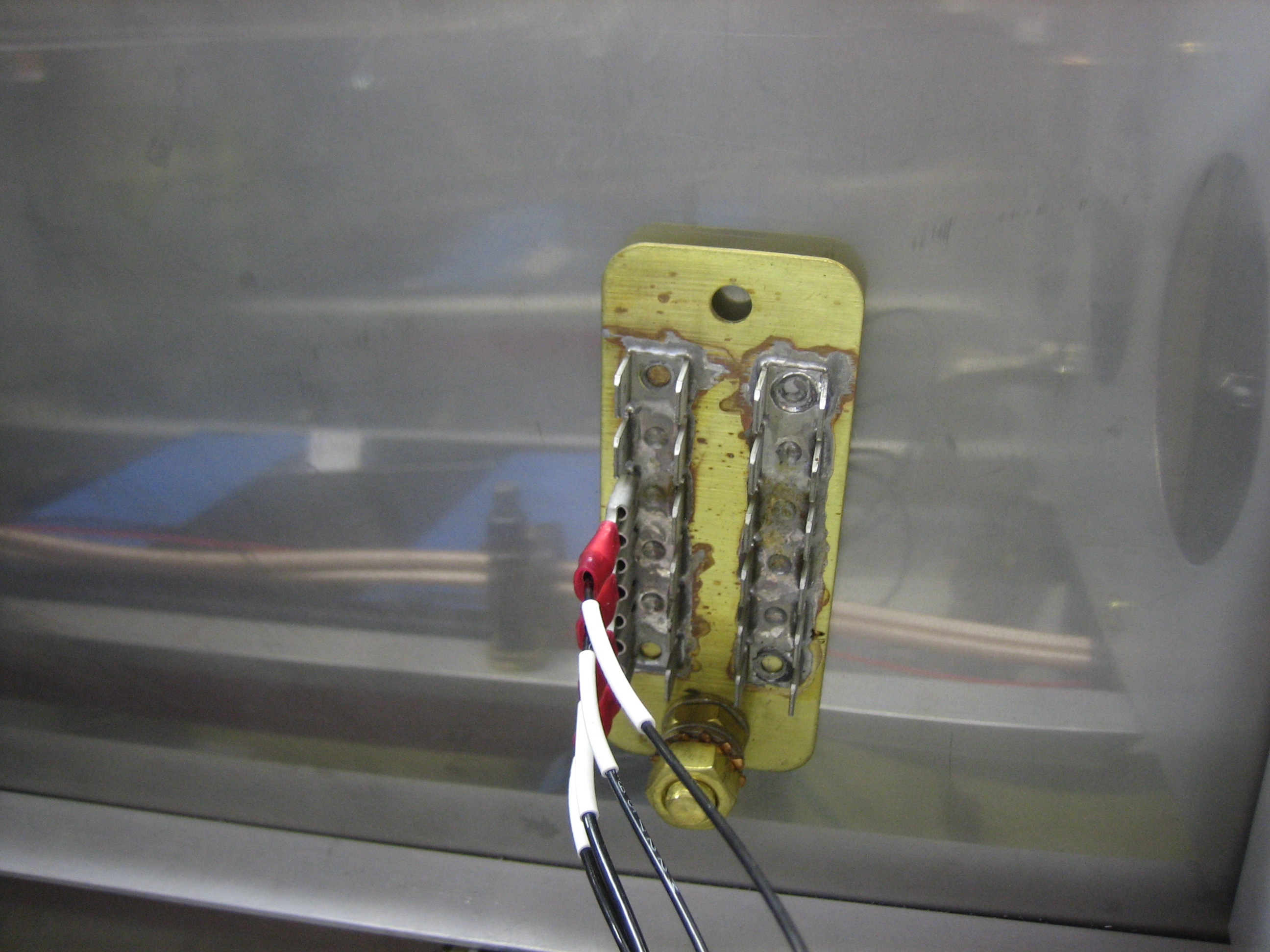
I ended up turning my ground block vertical. I’m really glad I held off on drilling the other hole in this. I’m going to hold off as long as possible in case I need to order a larger one. If I can use this one, I may turn it another 90º clockwise so that it’s still horizontal.
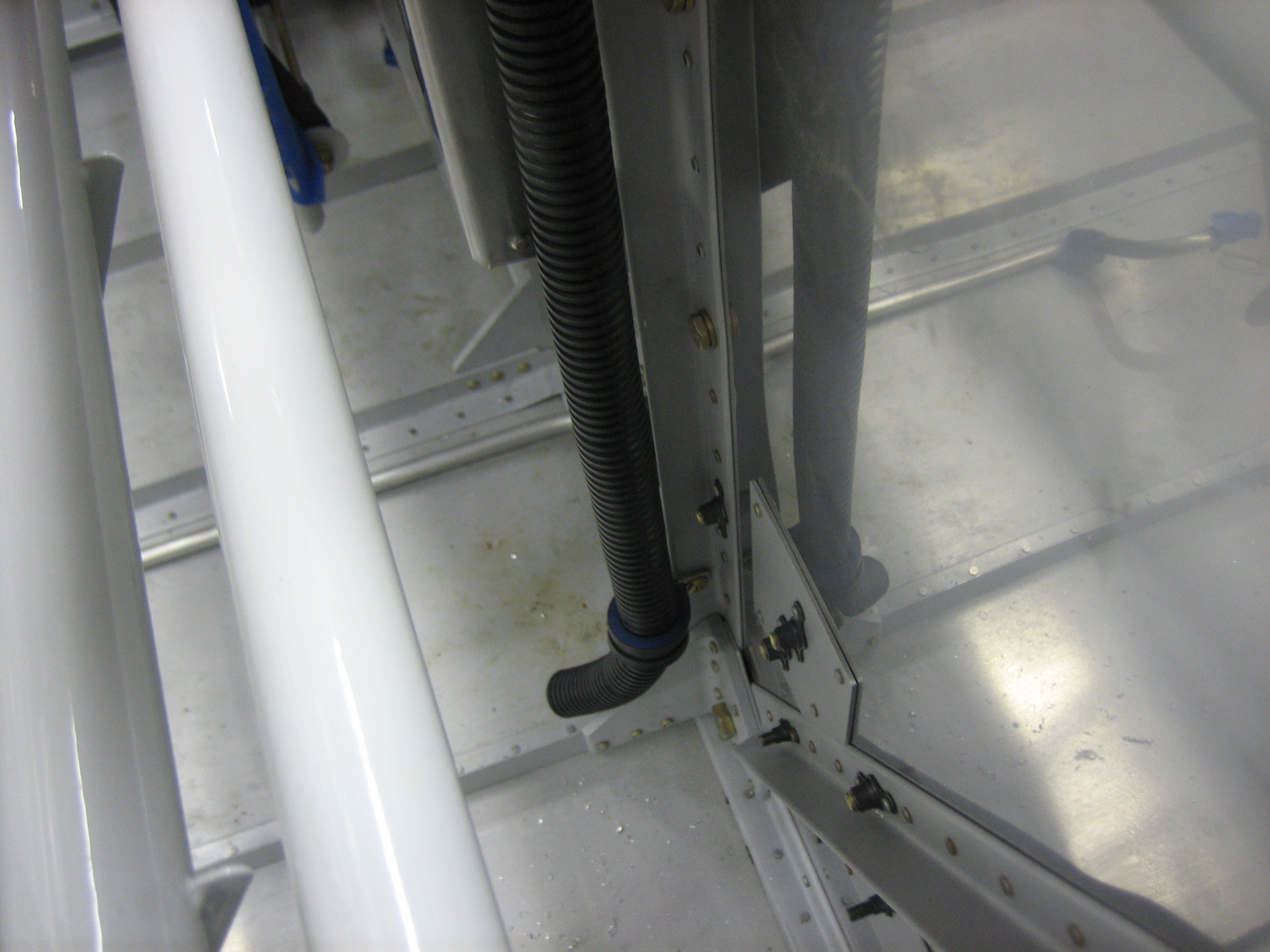
Here’s the reason I turned the ground block. I installed the firewall wiring conduit per drawing OP-30. This will be used to route wires front the front of the aircraft to everywhere aft of here.
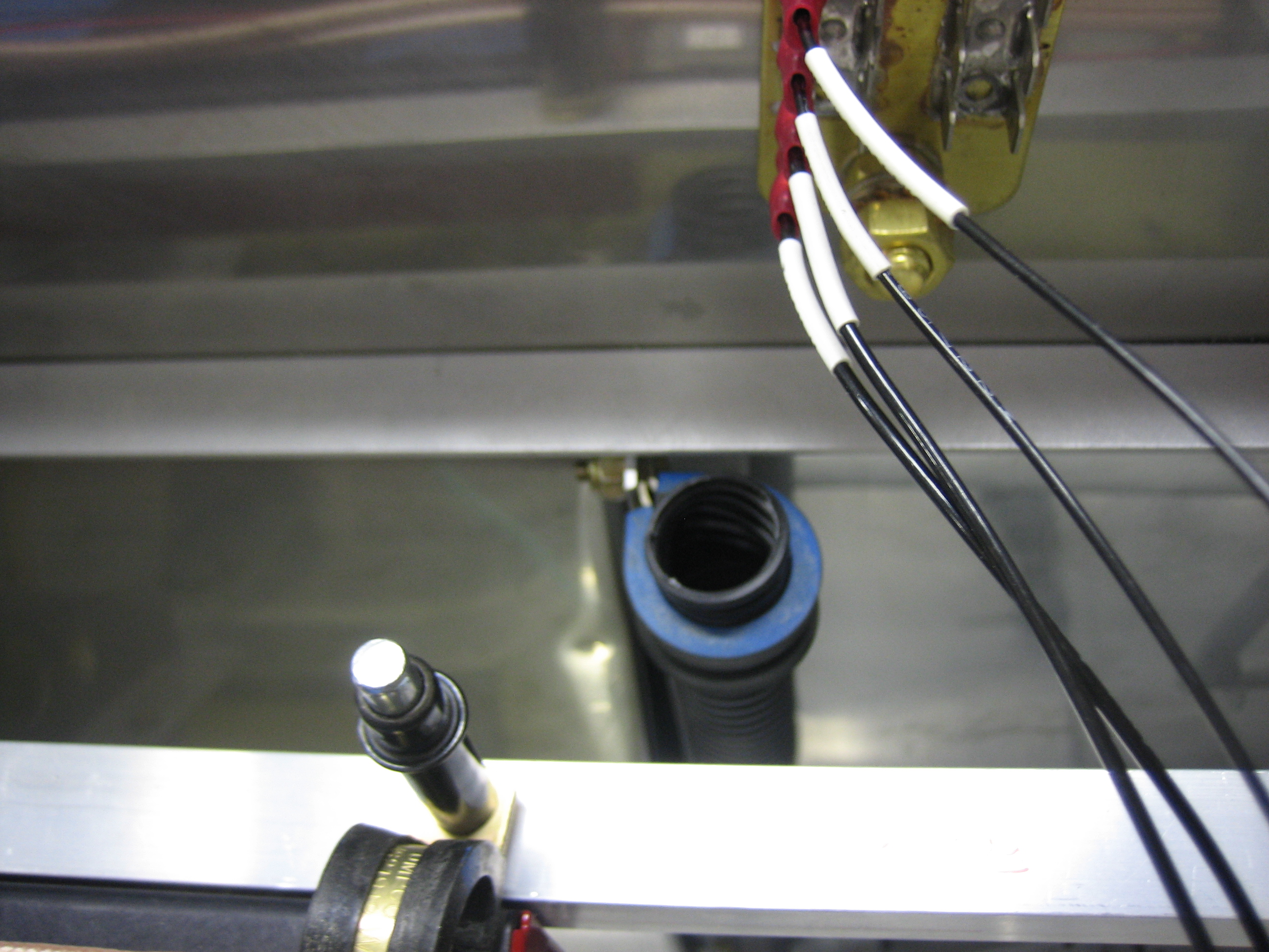
The conduit follows one of the firewall stiffeners and goes through another adel clamp near the bottom. It then steps inside the stiffener (where there is already a hole in the cover) and will go under the center floor cover back to the spar.
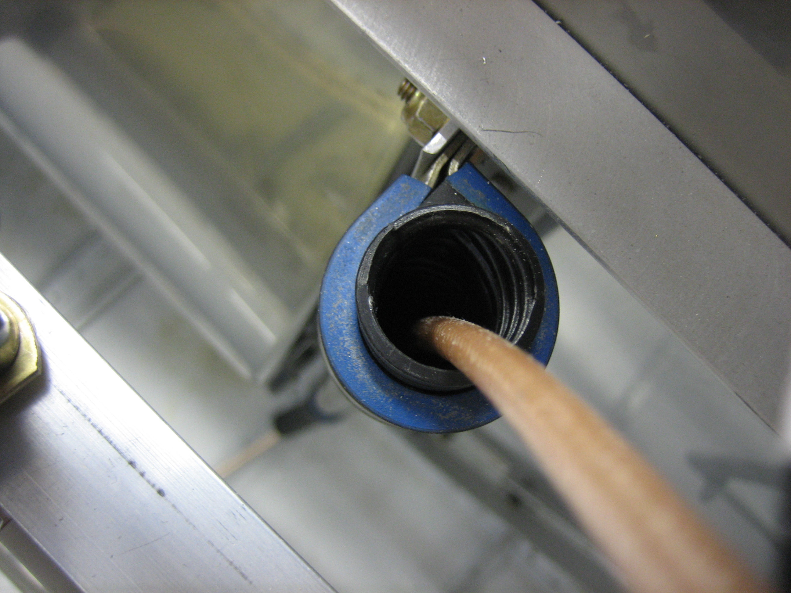
I pushed a piece of RG-400 through the conduit to get an idea how much space I’ll have in the conduit and figure out how I’m going to route the wires. There are going to be a ton of wires that have to run through this conduit:
Geez, after listing all these, I can’t possibly see that they’ll all fit through the conduit (even though most are pretty small relative to the RG-400). I’ll either run the wires through the adel clamps directly and wrap the wires with split tubing, or possibly run a second conduit down the left side of the center section.
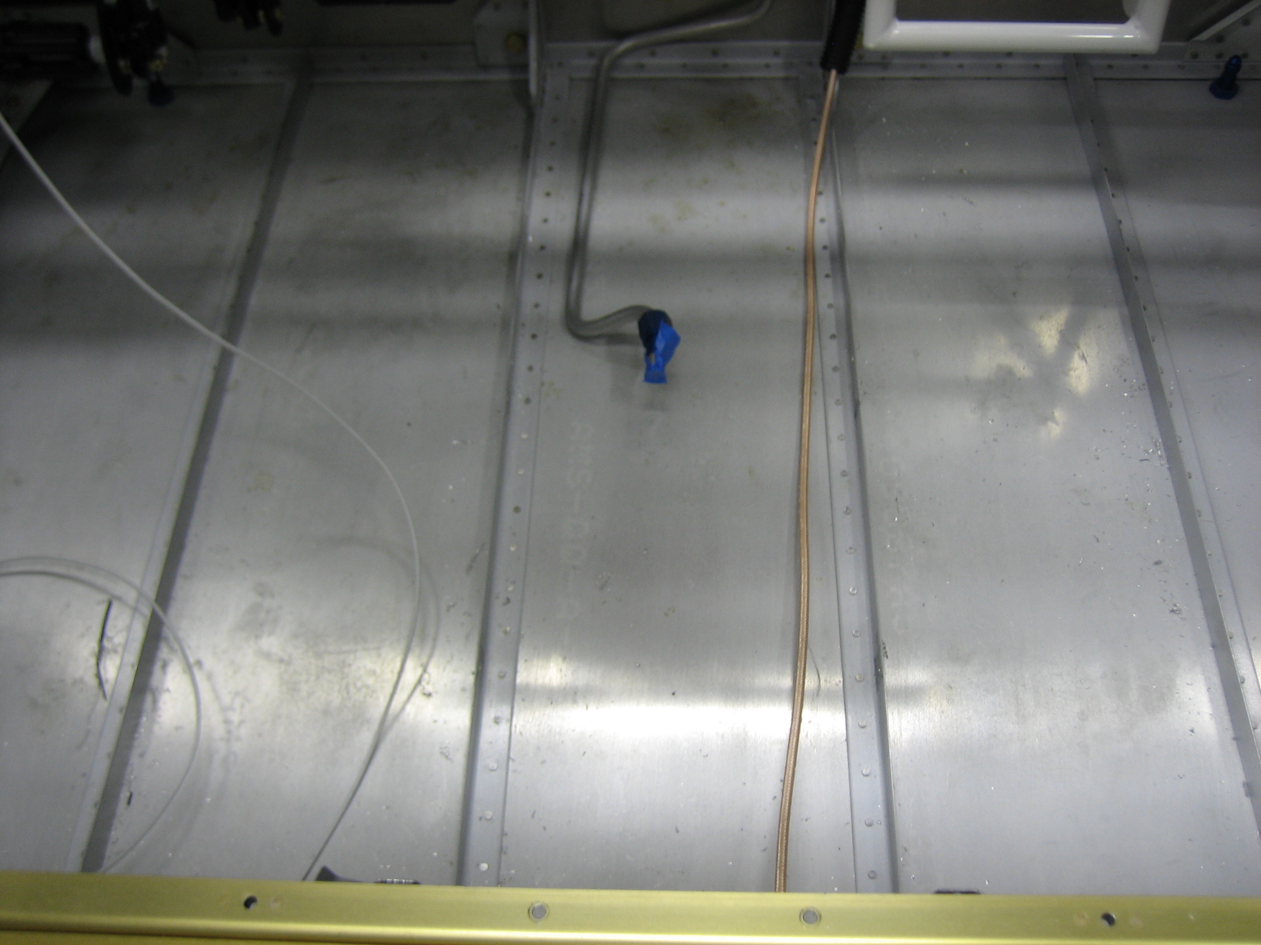
The wires exit the bottom of the conduit and will run along the floor. I’ll add anchors along the floor to keep the bundle secure.
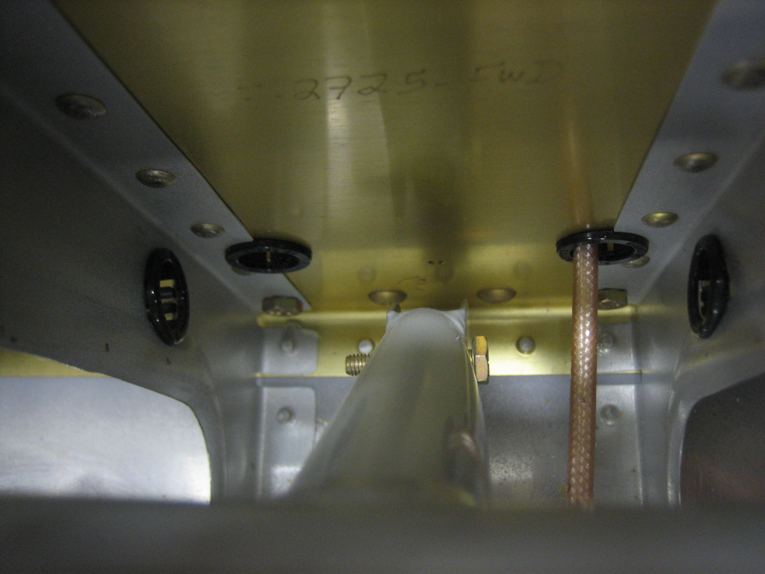
The wire exits the back of the spar near where the elevator horn sits. I’m not sure I like where Van’s suggests you put the snap bushings in the ribs. The wires have to make a fairly sharp turn to go through the ribs. This is fine for all of the small wires, but the RG-400 has a minimum bend radius of 1″, so that might not work.
Another possibility I’ve seen builders use is to cross the wires and penetrate the rib on the opposite side of the spar penetration (though obviously below the push tube). I’d need to drill new rib penetrations which would be challenging given the spacing between the ribs. This certainly allows a generous bend radius in the wires though.
I also ordered my interior from Classic Aero Designs. I’m going with the aviator seats with headrests, side panels, and full carpet. I also added in the hooker harnesses with matching leather pads. This will be a relatively heavy interior compared with the minimal cloth interior that many builders go with, but I really want a completely finished leather interior.
My tech counselor, Brian Dal Porto, stopped by tonight to check out my progress. The last time he stopped by was near the end of the wing construction which was about 19 months ago (holy crap, has it really been that long?). He checked out my fuselage construction, as well as engine installation and wiring. He said everything looks good and there wasn’t anything I needed to change which is great.
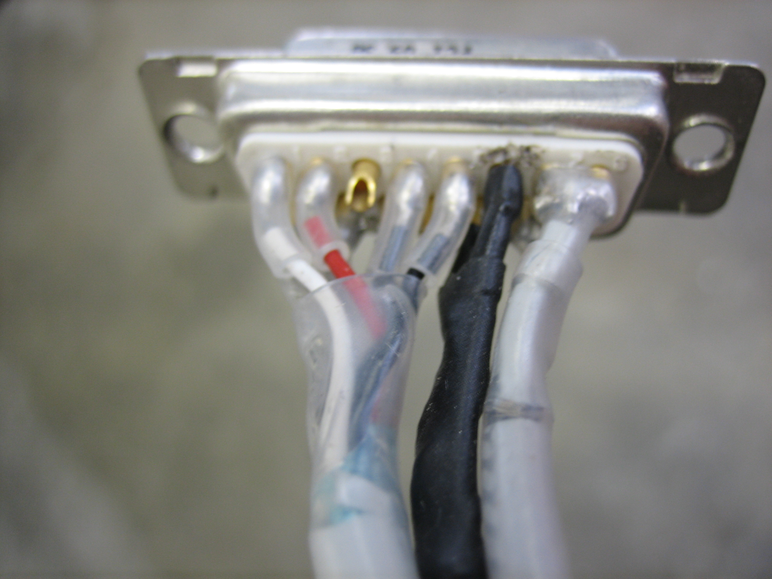
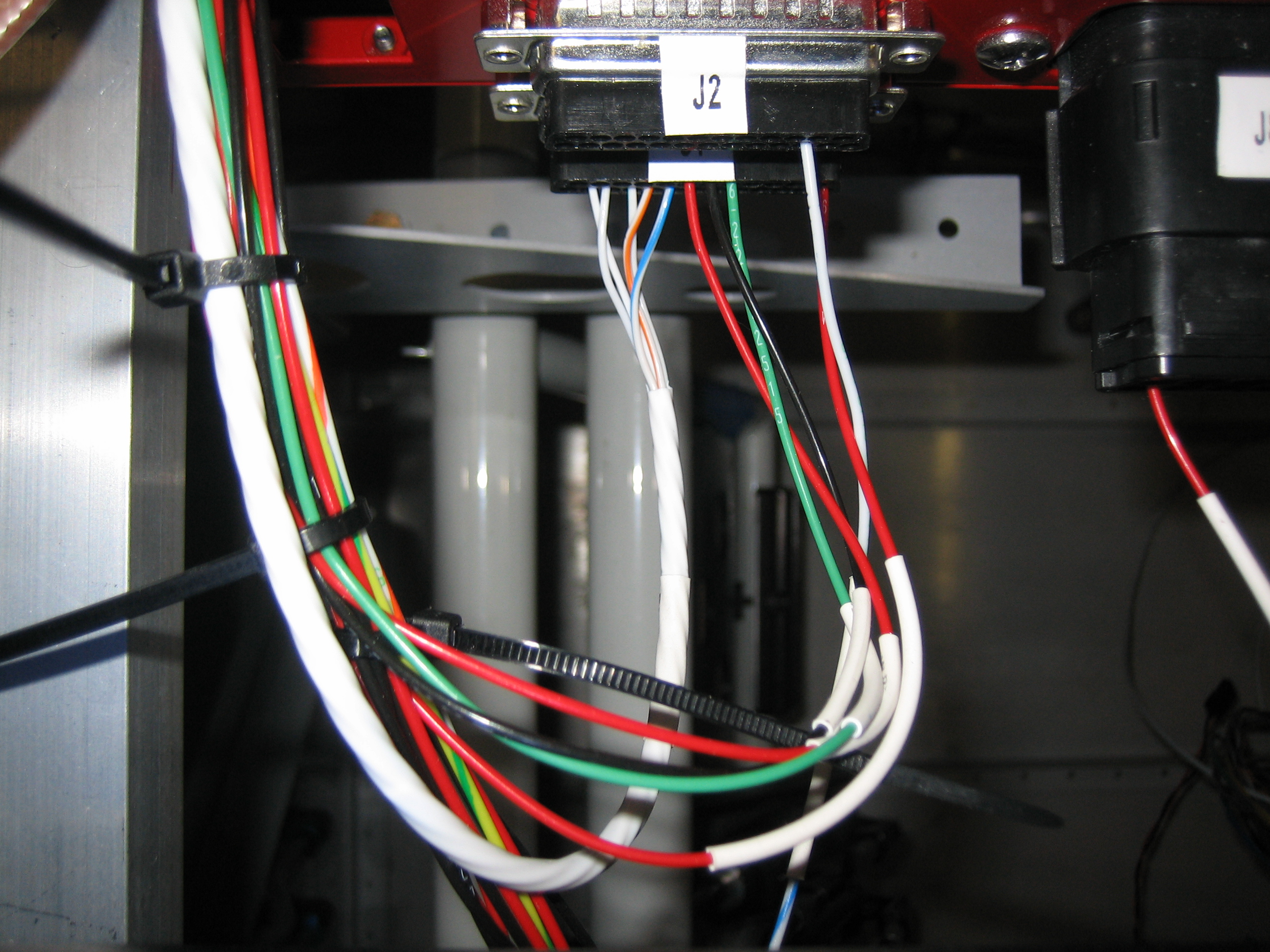
After he left, I took care of a couple of small tasks before heading in to get some work done for my day job. First up, I ran a cable for the elevator trim. This is a 5-conductor cable from Ray Allen that is specifically meant for wiring their trim systems. It contains five 26AWG wires that match the colors of the wires coming out of the trim and position sensor boxes. I was hoping that one 25′ cable would be enough to do both the aileron and elevator trim wiring, but it was quite a bit short. I’m going to replace my flap position sensor wires with another piece of this, so another 20′ should be plenty for the aileron trim and flap position. Here’s the wire where it comes out of the J1 connector on the VP-X (the five small wires that come out of the connector and go into the larger white cable. You can’t see it, but there is a heat shrink label on the cable.
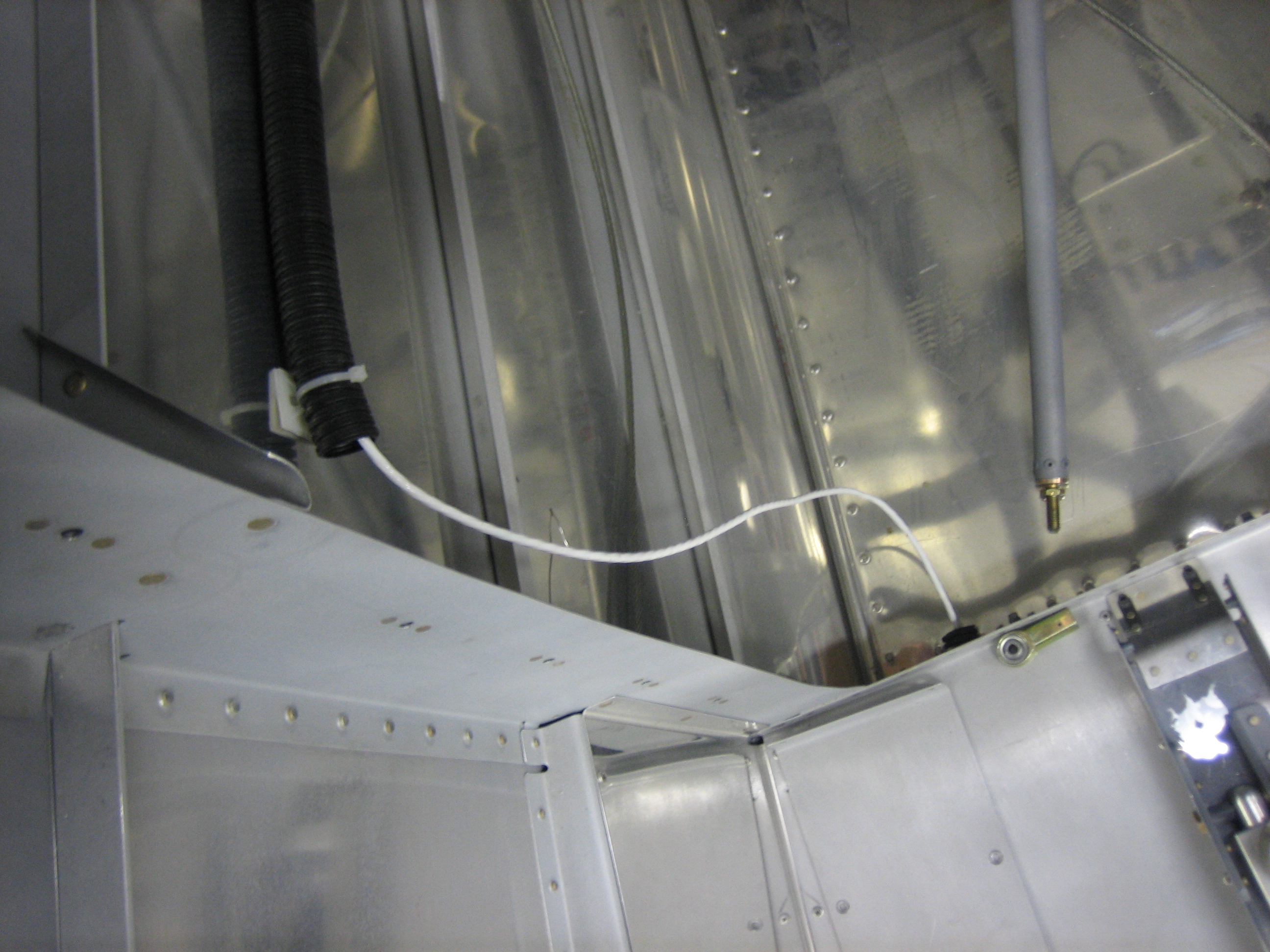
The cable runs down the forward center tunnel and under the copilot’s seat and through the right conduit and comes out here behind the baggage bulkhead. There will be an adel clamp here securing this to the bulkhead as it runs up to the tail conduit (along with the tail position/strobe wires).
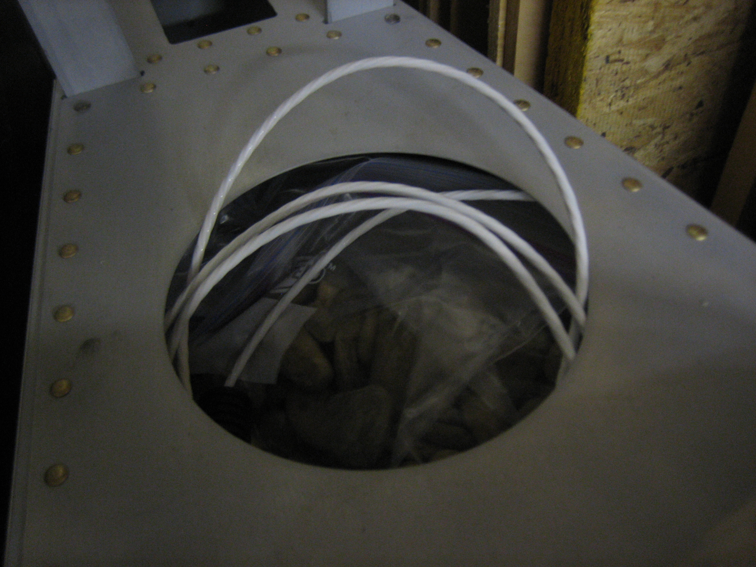
There’s a few extra feet of wire back here. I’ll cut it to length when I mount the tail.
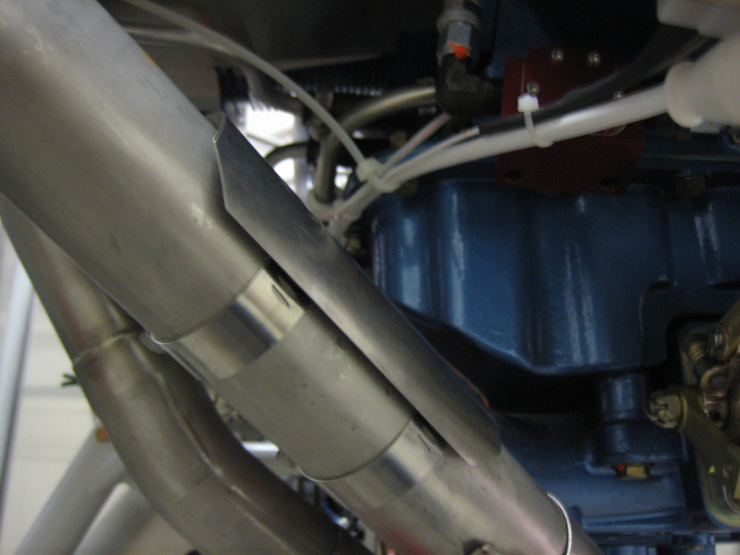
I also received a couple more 4″ exhaust heat shields. I mounted one on the #4 pipe to protect the wires running through this area.
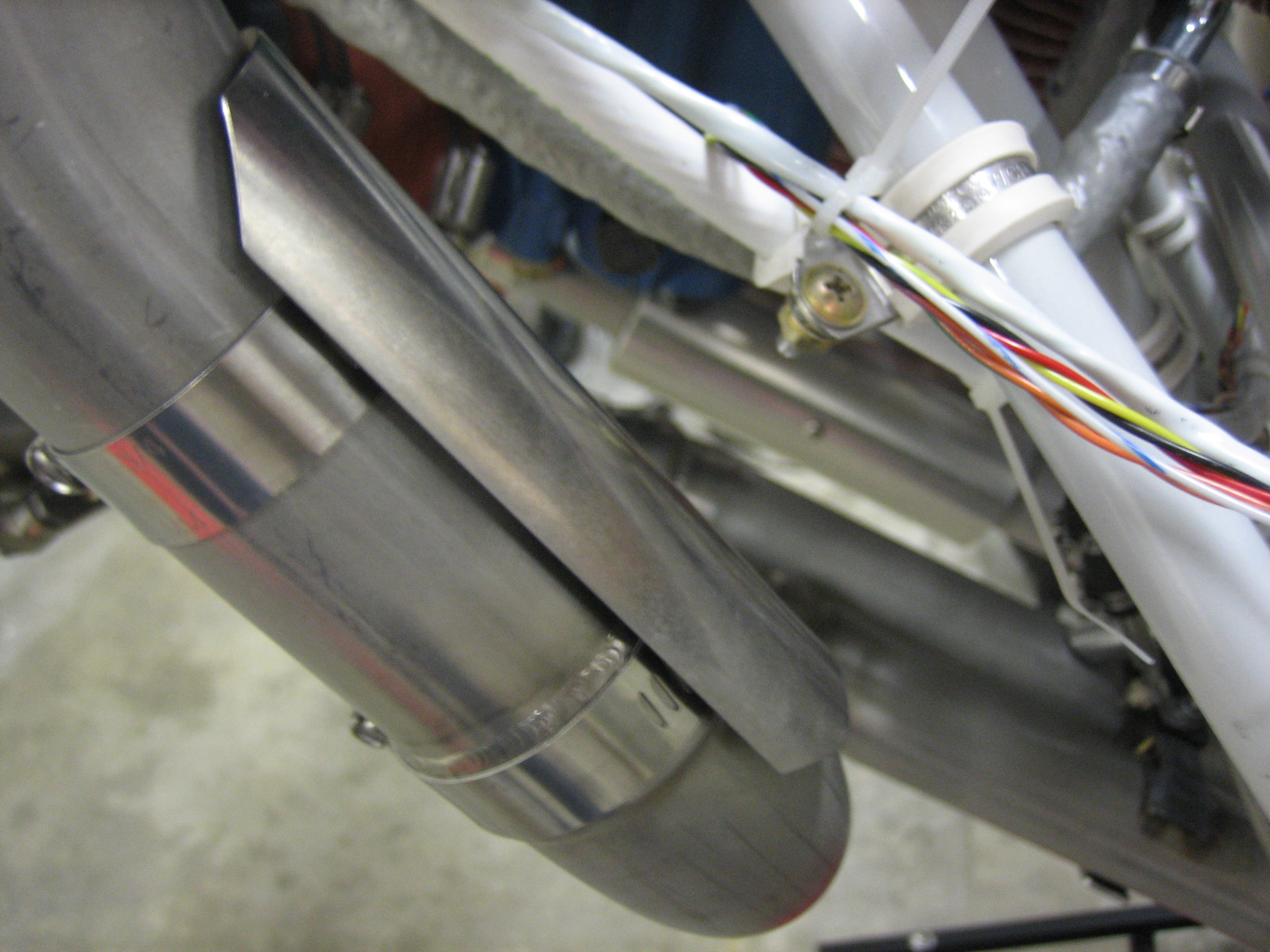
I also mounted two on the #1 pipe. The first is just above the heat muff to protect the throttle cable.
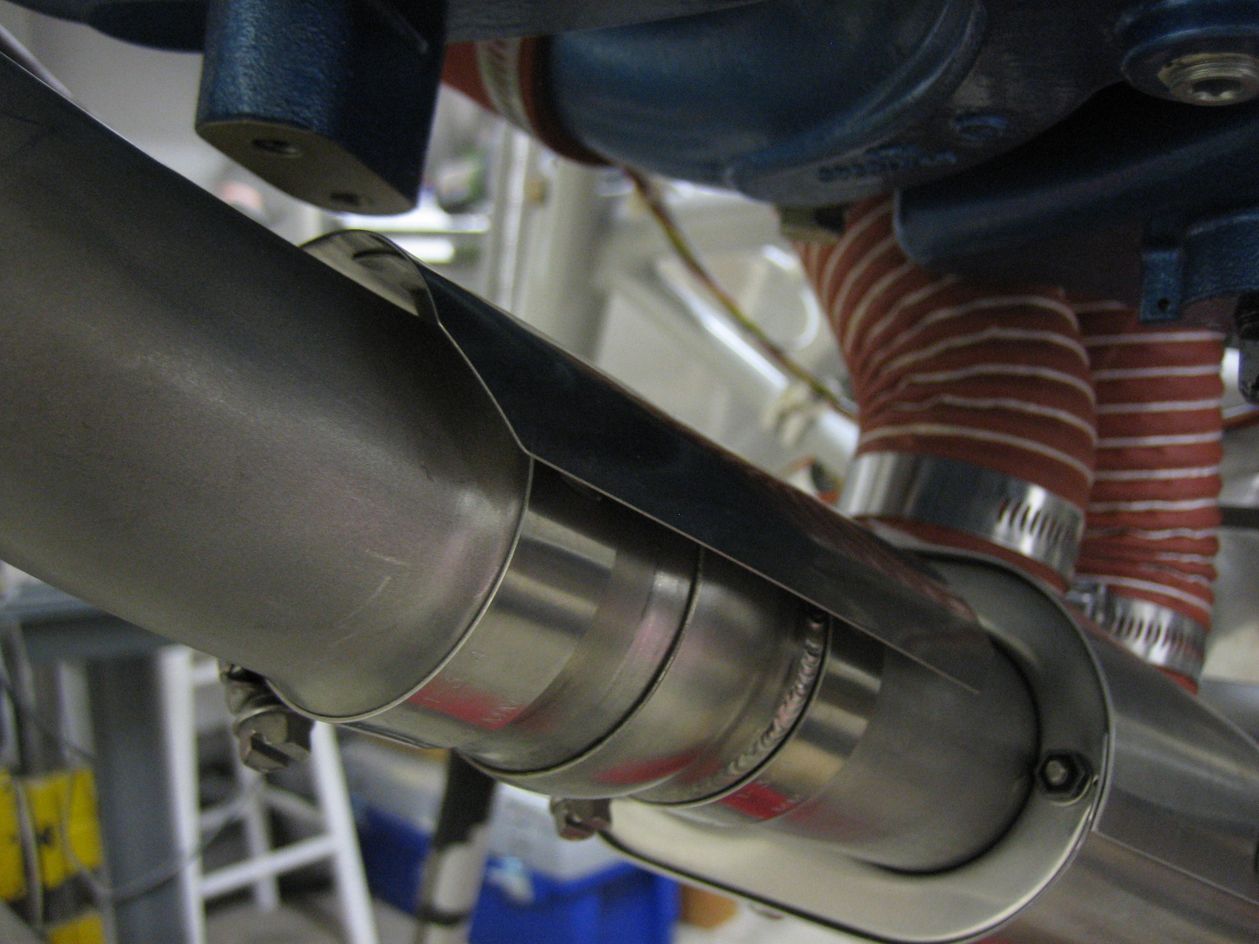
The second is a little farther up the pipe to provide some protection for the alternator wires and fuel flow sensor.
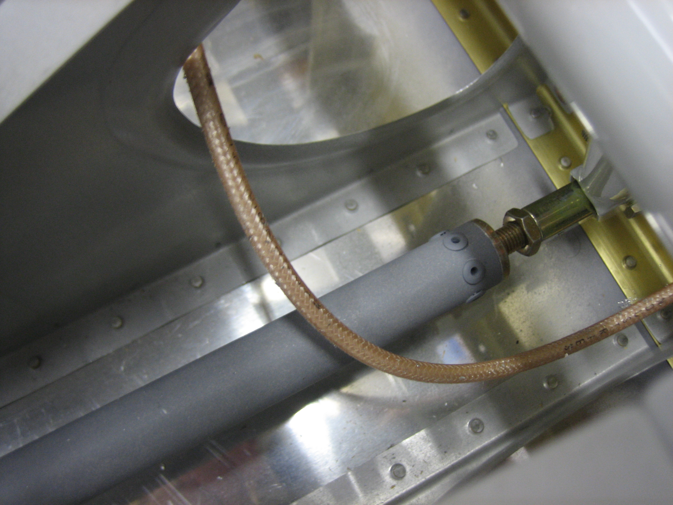
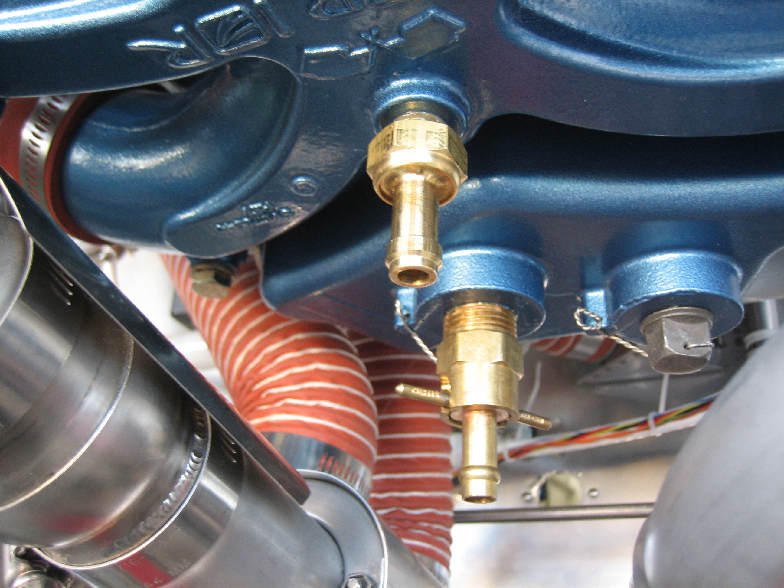
I installed the sniffle valve in the aft port in the intake manifold (the upper brass fitting). This is a check valve that opens when on the ground to allow excess fuel or water that leaks into the engine manual to drain out of the bottom of the engine and onto the ground. I also drained the preservative oil out of the engine and installed the quick drain plug into the sump and safety wired it.
I then mixed up some proseal and attached the air vents to the side of the fuselage. I drilled a couple of holes for alignment purposes. I’ll fill these in later with some filler. A lot of builders pop rivet these on, but proseal is tenacious stuff and will hold these quite well. This is the left side.
…and this is the right.
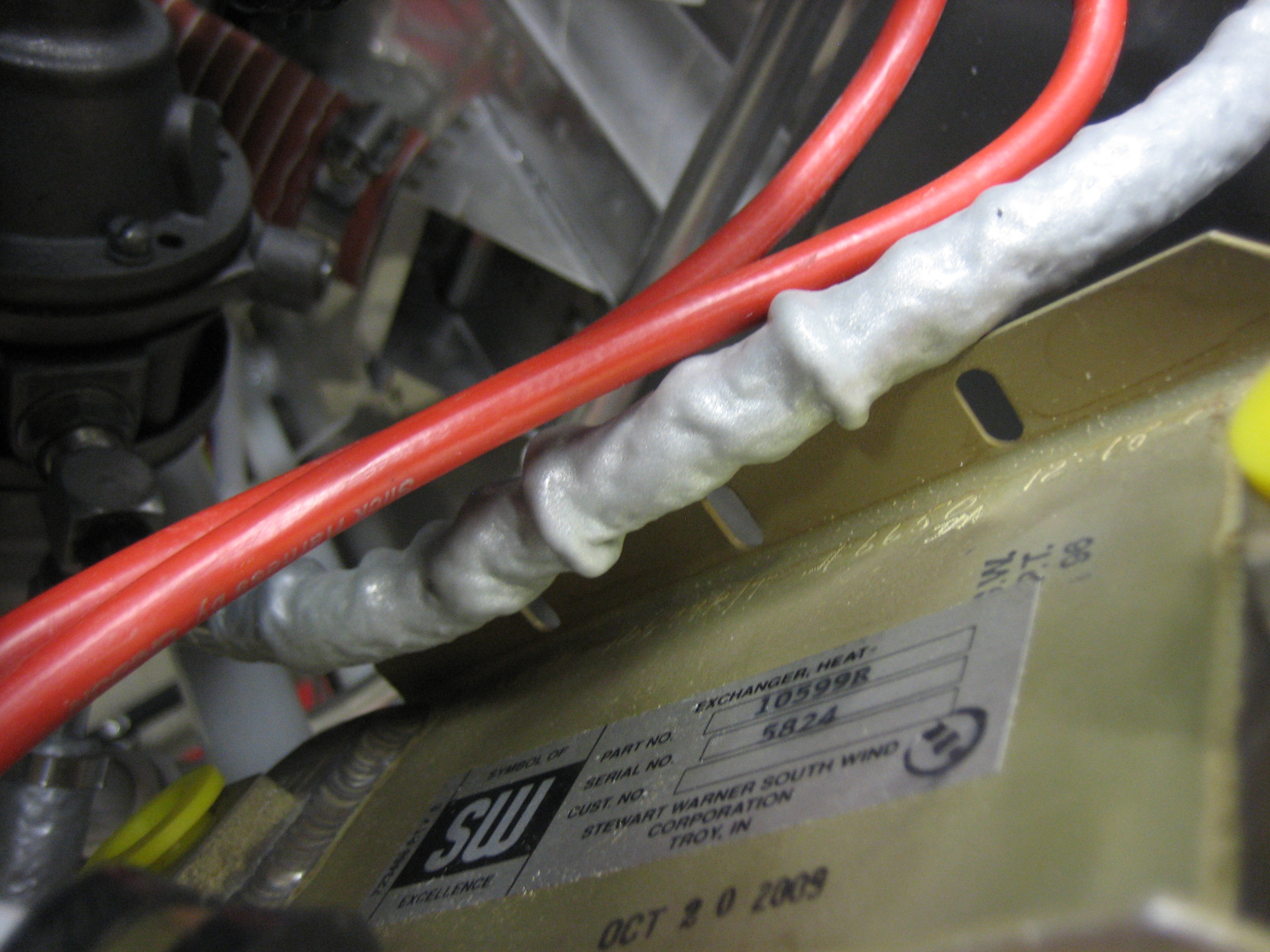
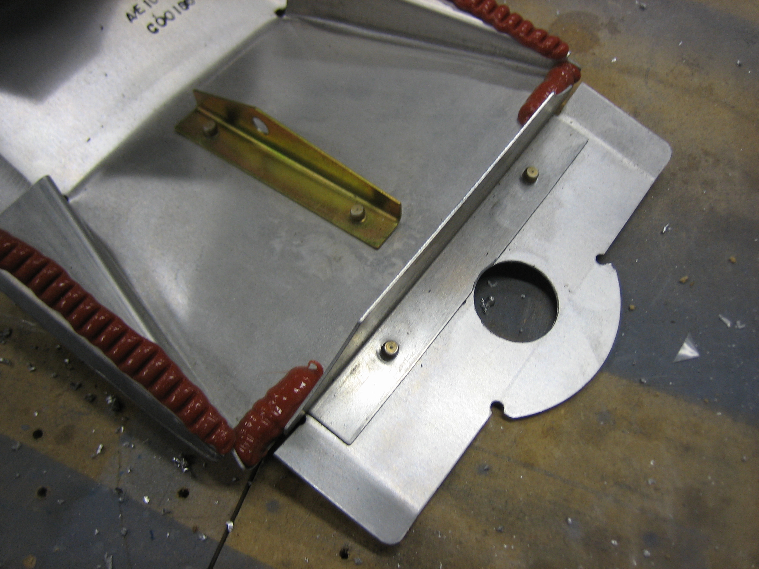
I’ve been toying with various install locations for the oil cooler. I would prefer not to mount it on the baffles for a couple of reasons. First, it’s really tight there because of the size of the 10559R oil cooler. Second, people already have problems with the baffles cracking due to the weight of the oil cooler. Since this oil cooler is larger than typical, it will contain more oil and will therefore weigh even more than normal. I would have to reinforce the baffles even more than builders normally need to carry the extra weight.
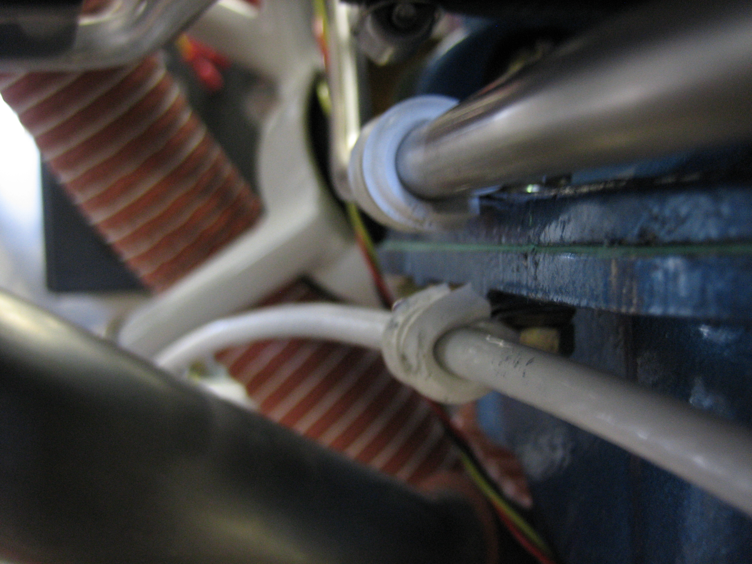
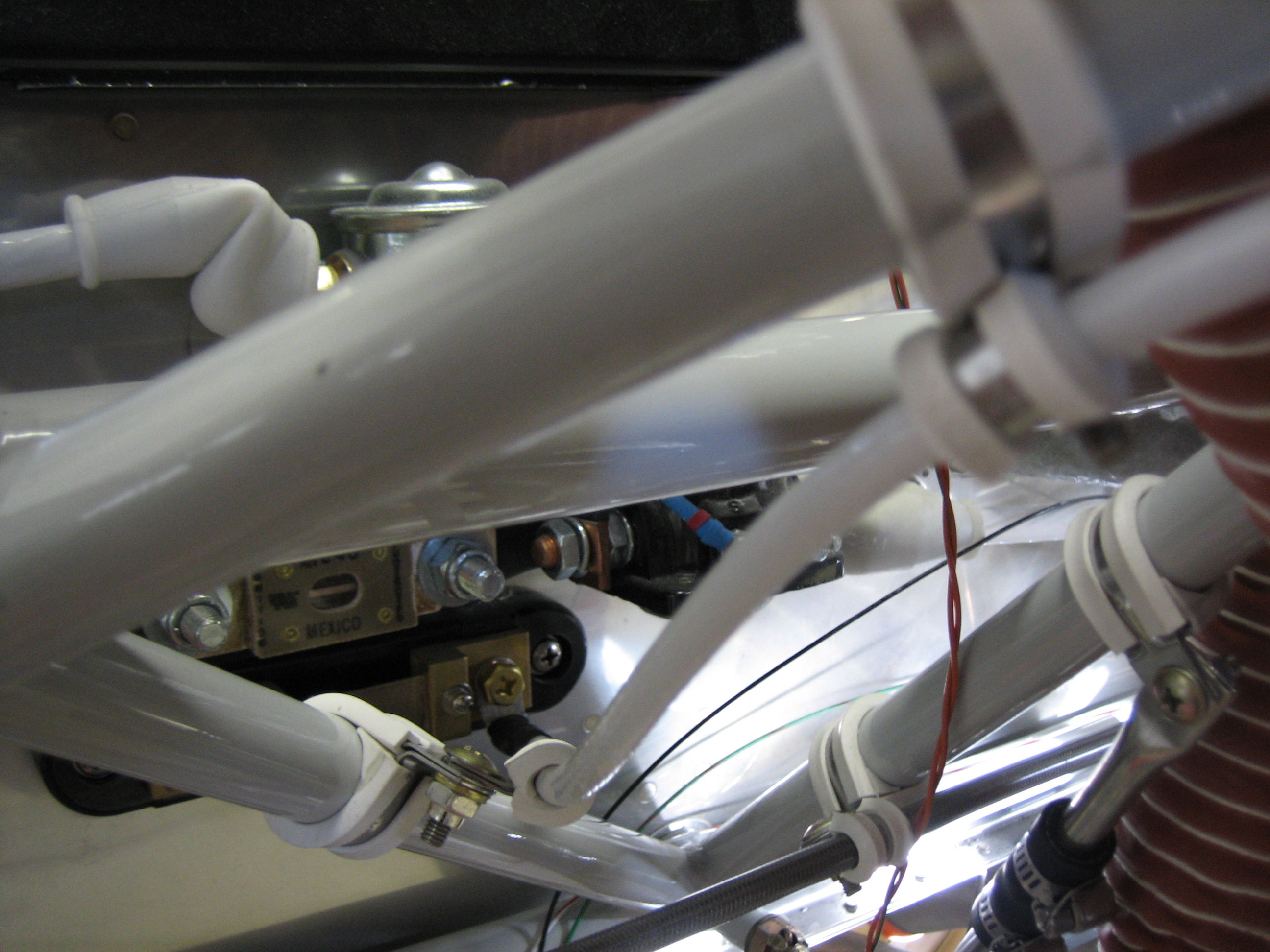
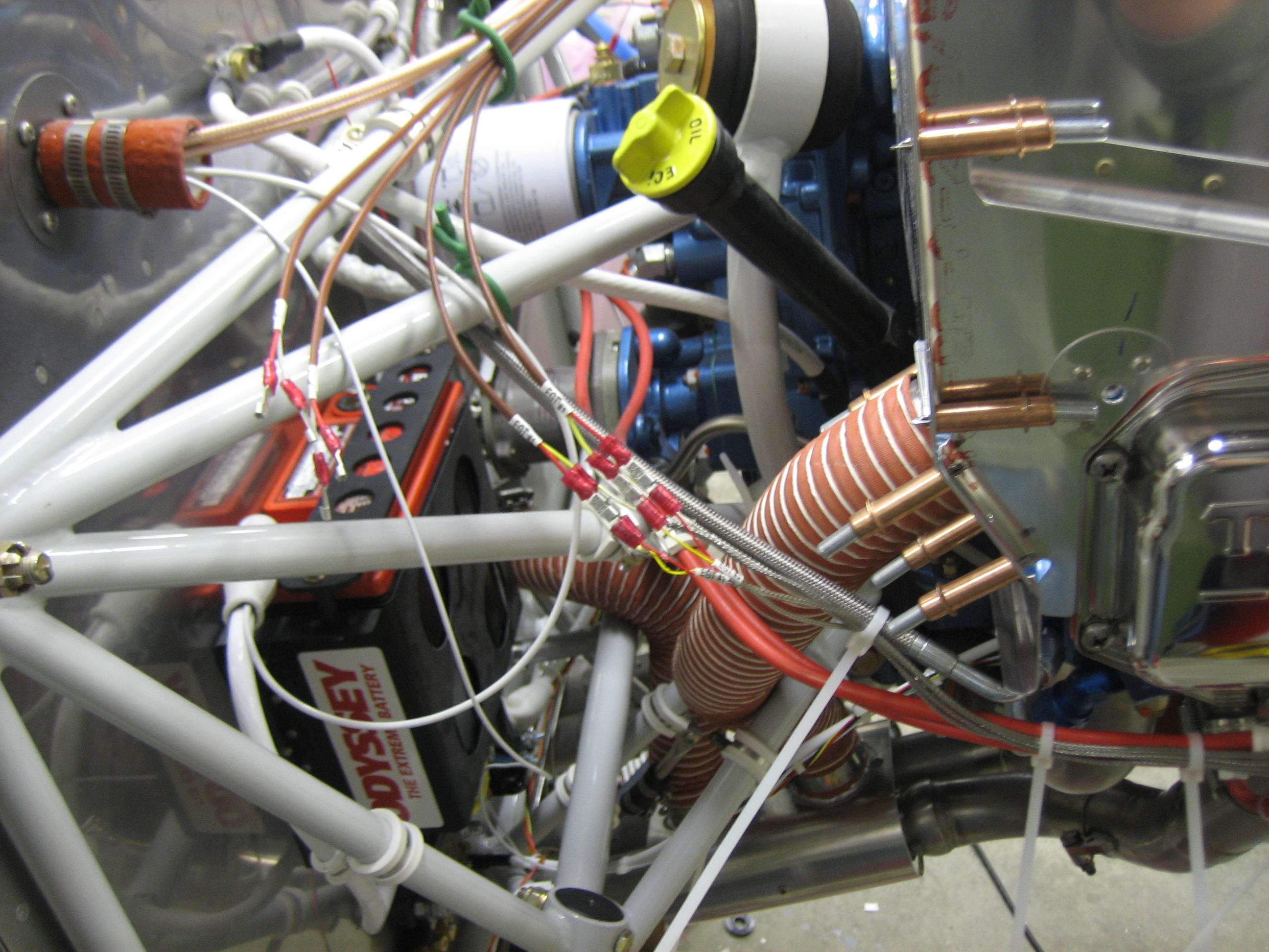
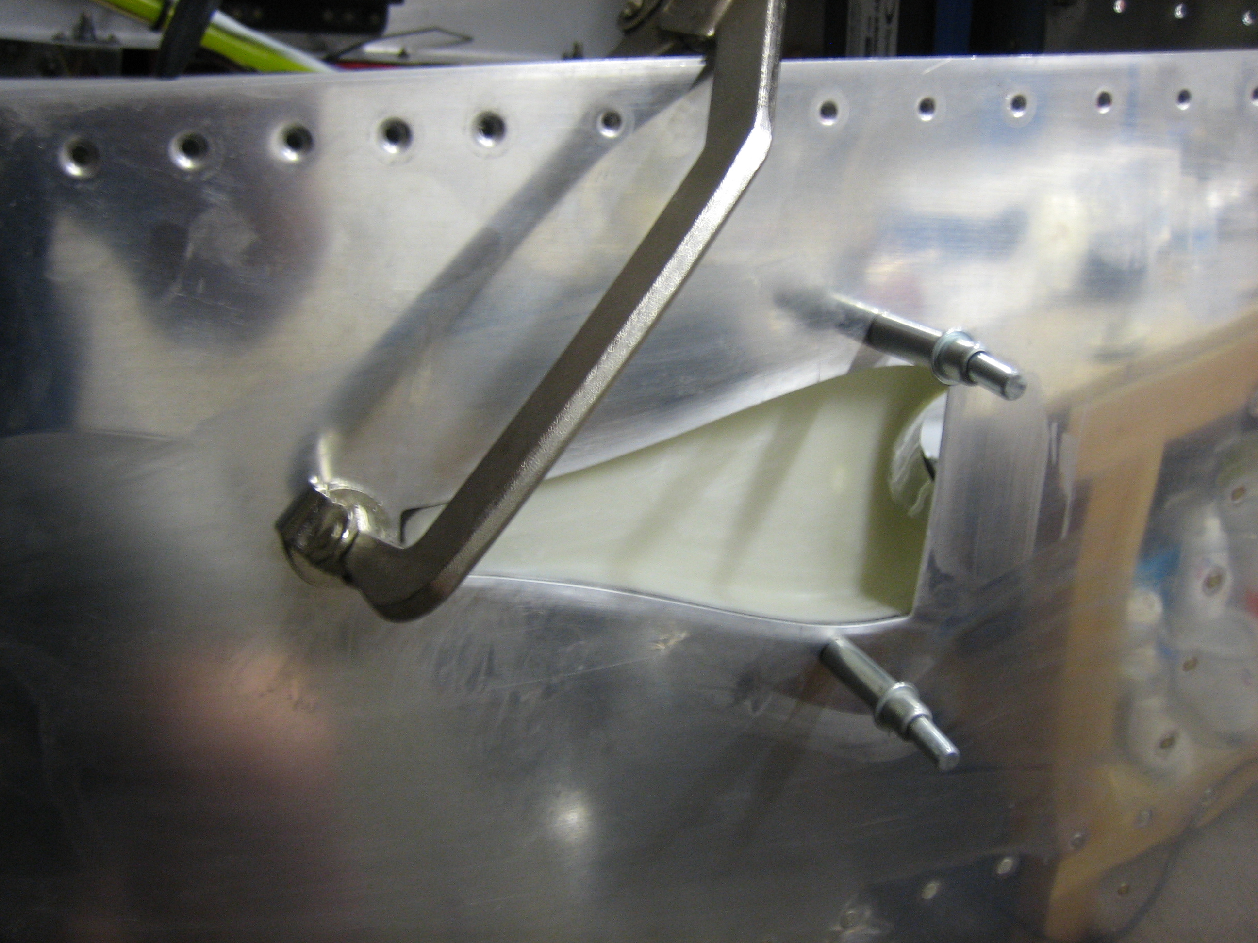
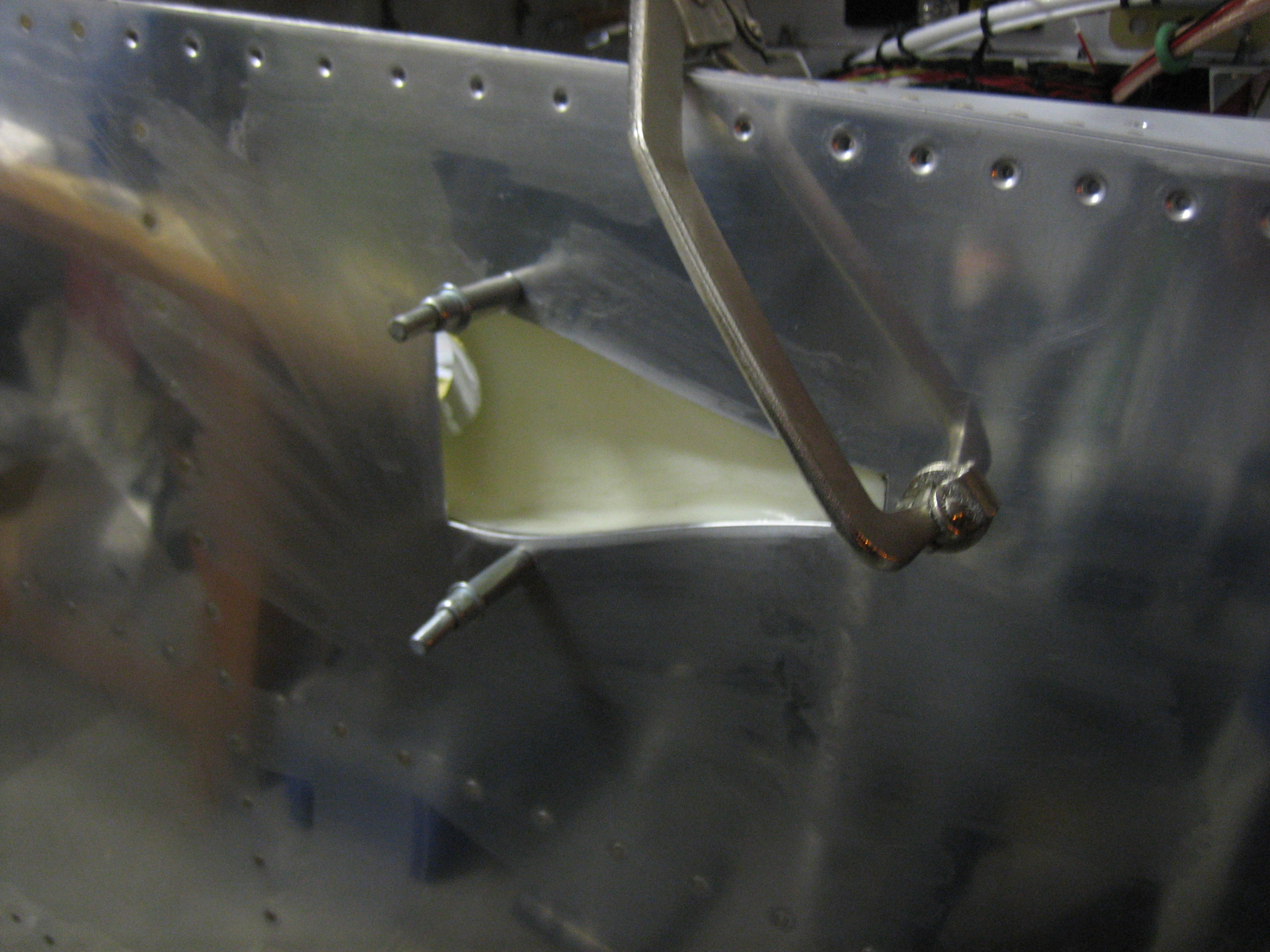
I tried various positions on the firewall, but things are really tight there. There is one spot that could work, but it would require building a custom bracket and significantly reinforcing the firewall. After playing with various mounting locations, I stumbled on the possibility of mounting it between two of the engine mount tubes. I mounted it temporarily using a few adel clamps to see if it would work. There’s a little bit of flex, but this is surprisingly strong. I can move the entire plane by pushing and pulling on this. If I go with this location, I’ll move it down a little bit and fabricate a bracket that lets me use two adel clamps on the top flange to prevent twisting. This will give me a little more clearance for the control cables as well as make the upper engine mount tube be a little move out of the way.
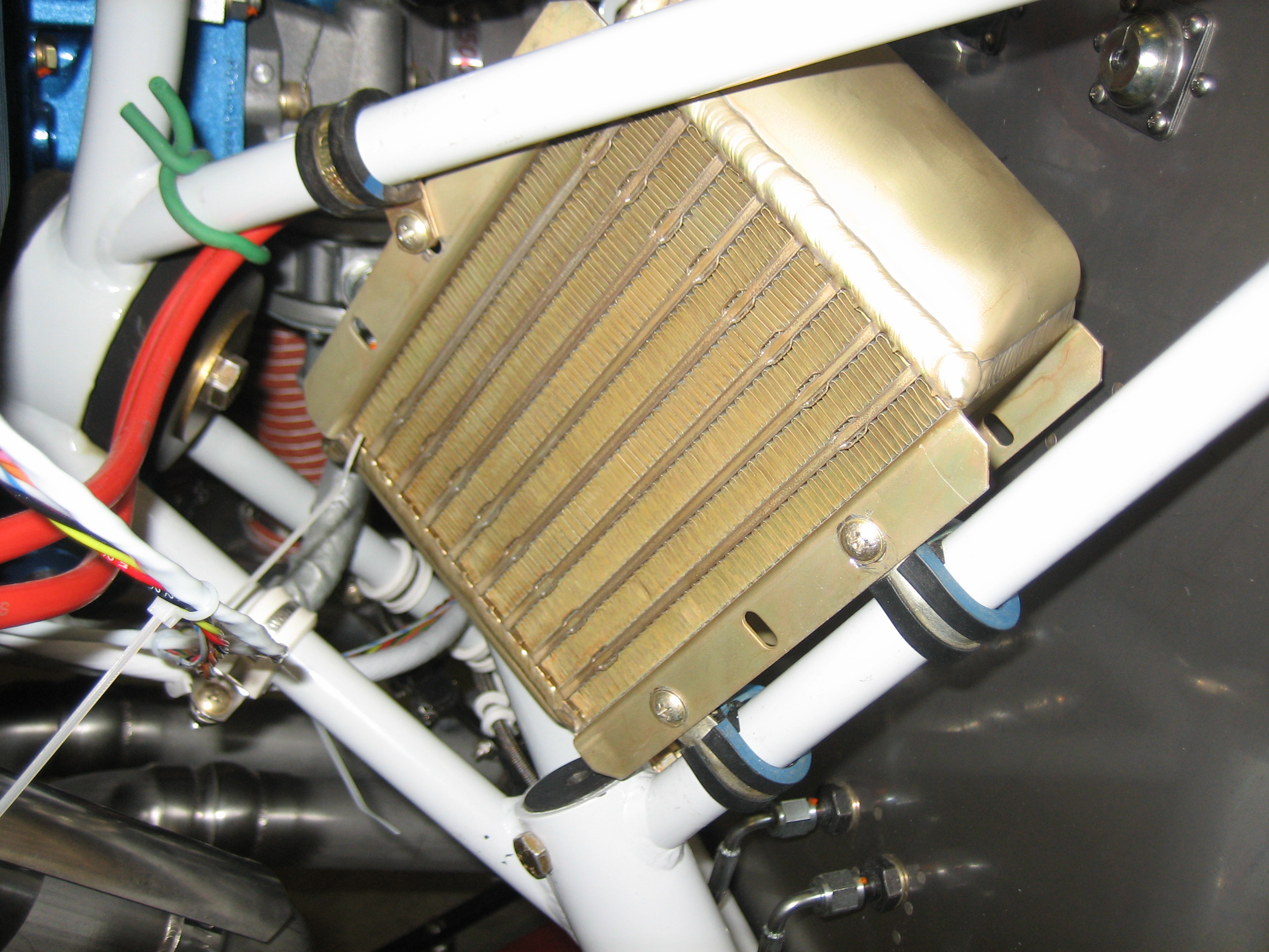
You can see that there is plenty of room between the back of the engine and the oil cooler. I will mount a flange on the back of the baffles (either 3″ or 4″) and run some scat tube down to a custom plenum that I will fabricate to direct the air through the oil cooler. I want to sleep on it and run it by the folks on vansairforce.net to make sure there aren’t any issues with this plan.
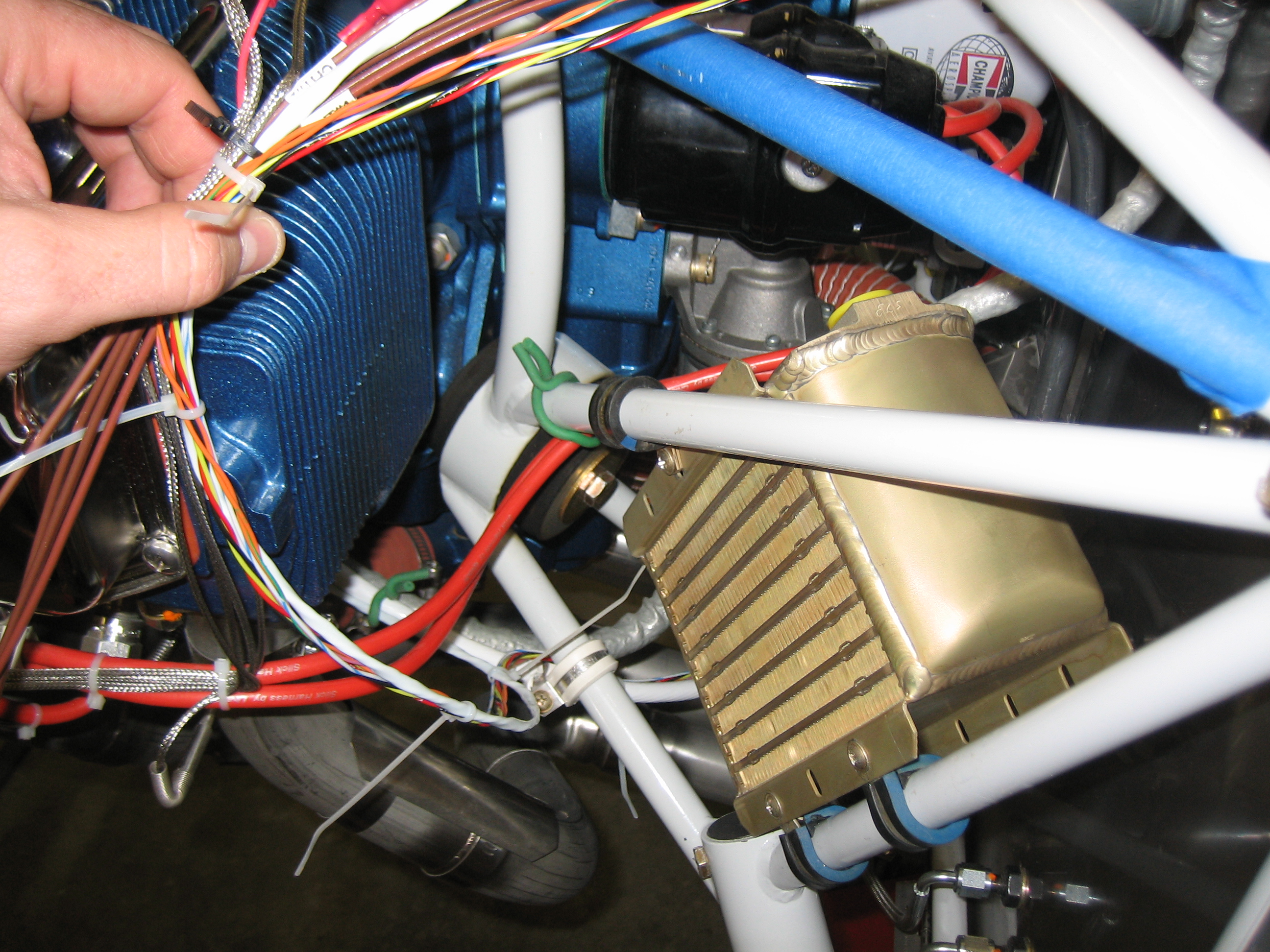
The fuel pressure line runs right by the back side of the oil cooler. I’ll install an adel clamp here to space the line a little bit away from the oil cooler flange.