Replaced Pitch Servo

Way back in September, I mentioned that since upgrading to SkyView 4.0, the SkyView system wasn’t finding my pitch servo.  After double checking the wiring at the request of Dynon, I couldn’t find any problems.  Dynon ended up sending me a new servo which completely fixed the problem.

I then spent a couple more hours working on the plenum mounting angles.  I have them pretty much ready to drill to the baffles.  I’m sure I’ll have to tweak the angles a bit to get the plenum to sit flat on them.

Started Drilling Plenum Mounting Angles

I started drilling the plenum mounting angles tonight.  I made it around halfway around the baffles before getting frustrated with the ones along the front of the engine.  These have the most curvature of any of the baffles and I kept splitting the metal with the stretcher.  I’ll probably end up having to section those angles to get them to curve that much.  Here’s the angles around the oil cooler bump out.

There will be a small gap here where the left and right sides of the aft wall join.  The plenum will span this and the gap should be tiny if not nonexistent.

Here’s the aft right side of the engine.  All of the corners are mitered, and I’ll install a nutplate that spans the gap in the corner to further tie these pieces together.

Worked on Cowl Inlets

I trimmed back the vertical walls on the inner ends of the cowl inlets so that they line up with the front edge of the ramps.  Here’s the right side.

And here’s the left side.

I trimmed the cowl inlets back so there is 3/8″ of clearance between the cowl and the ramps.  This will provide room to slip the cowl in place while pulling the baffle seal material through the gap.  The baffle seal material will span this gap to prevent cooling air from leaking through here.  Here’s the right side.

And here’s the left side.

I then started fabricating the cowl inlet seal retaining strips for the lower cowl out of some 0.063″ strip stock.  The baffle seal material will be sandwiched between the cowl and the retaining strip.

I laid out and drilled three holes through the cowl and retaining strip.

I did this to both strips and then installed some #6 nutplates.

Fit Lower Left Cowl Inlet Baffle Seal

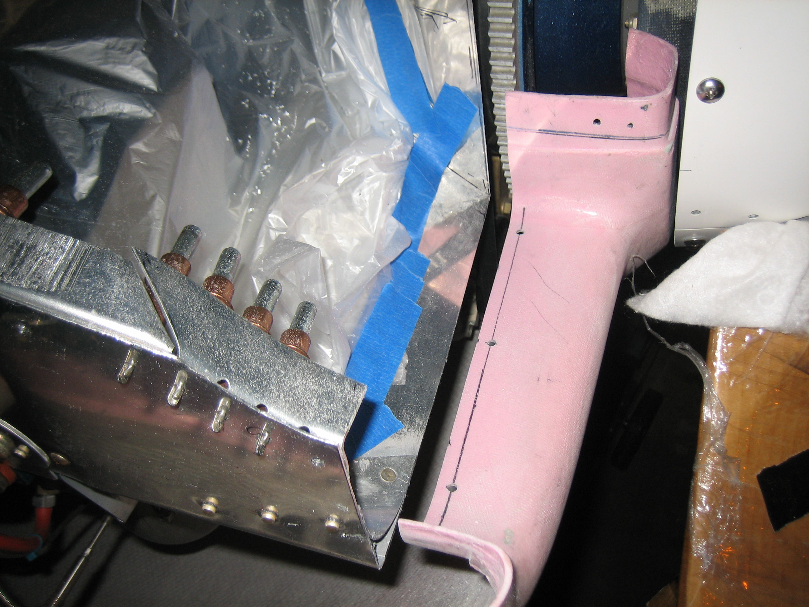
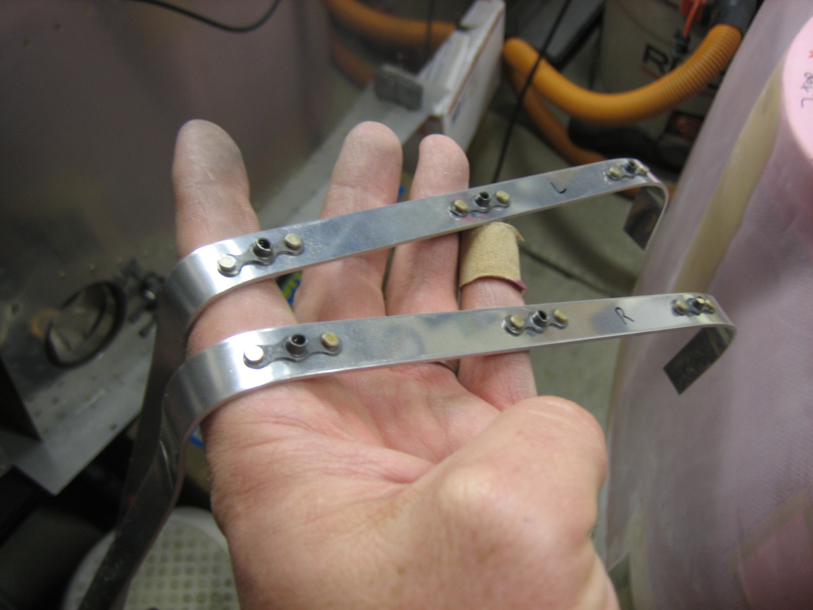
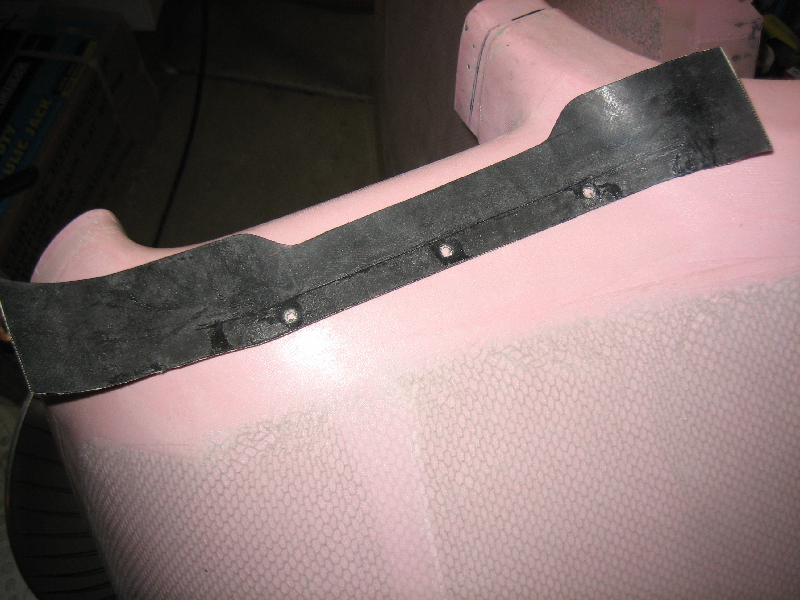
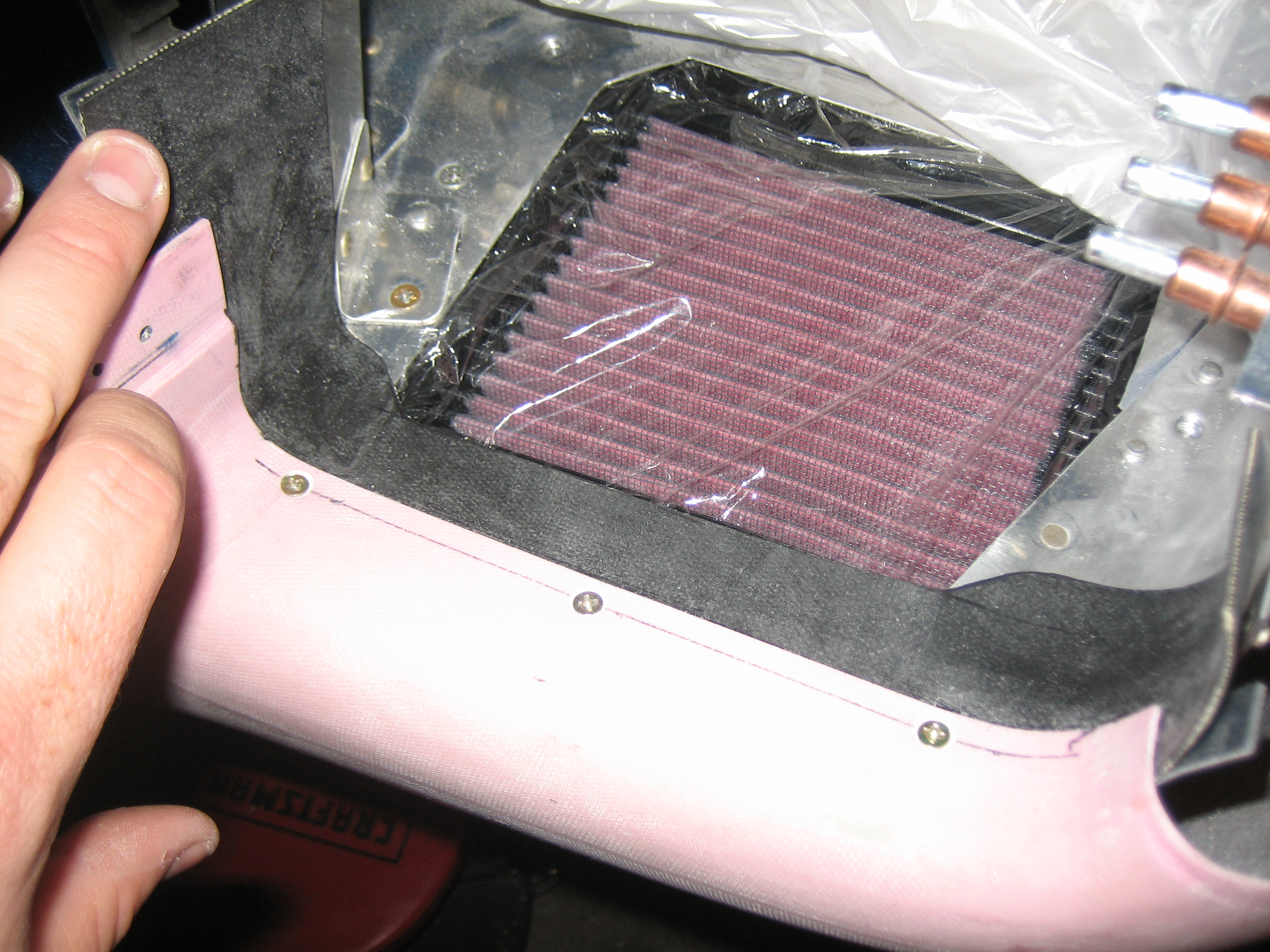
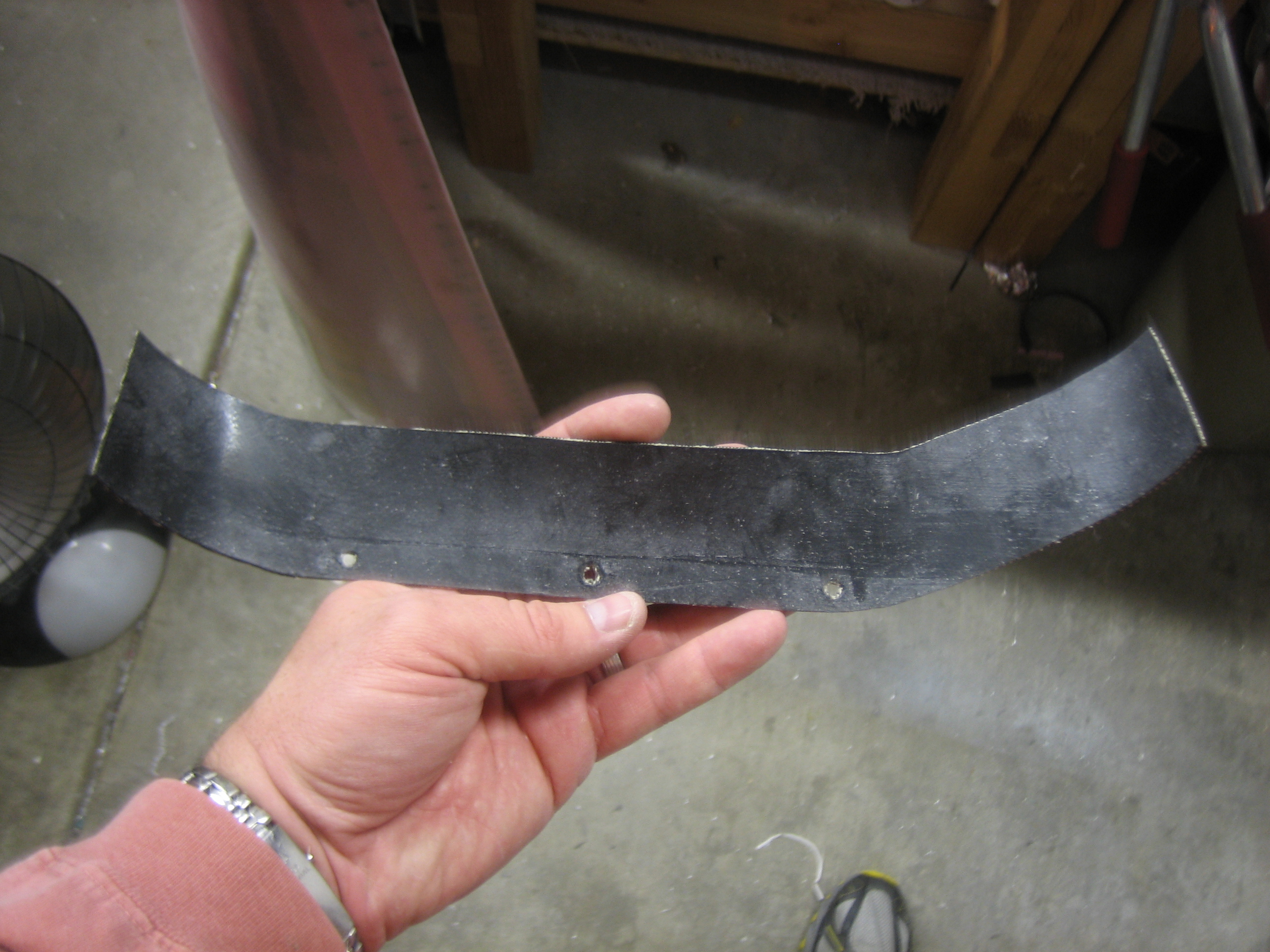
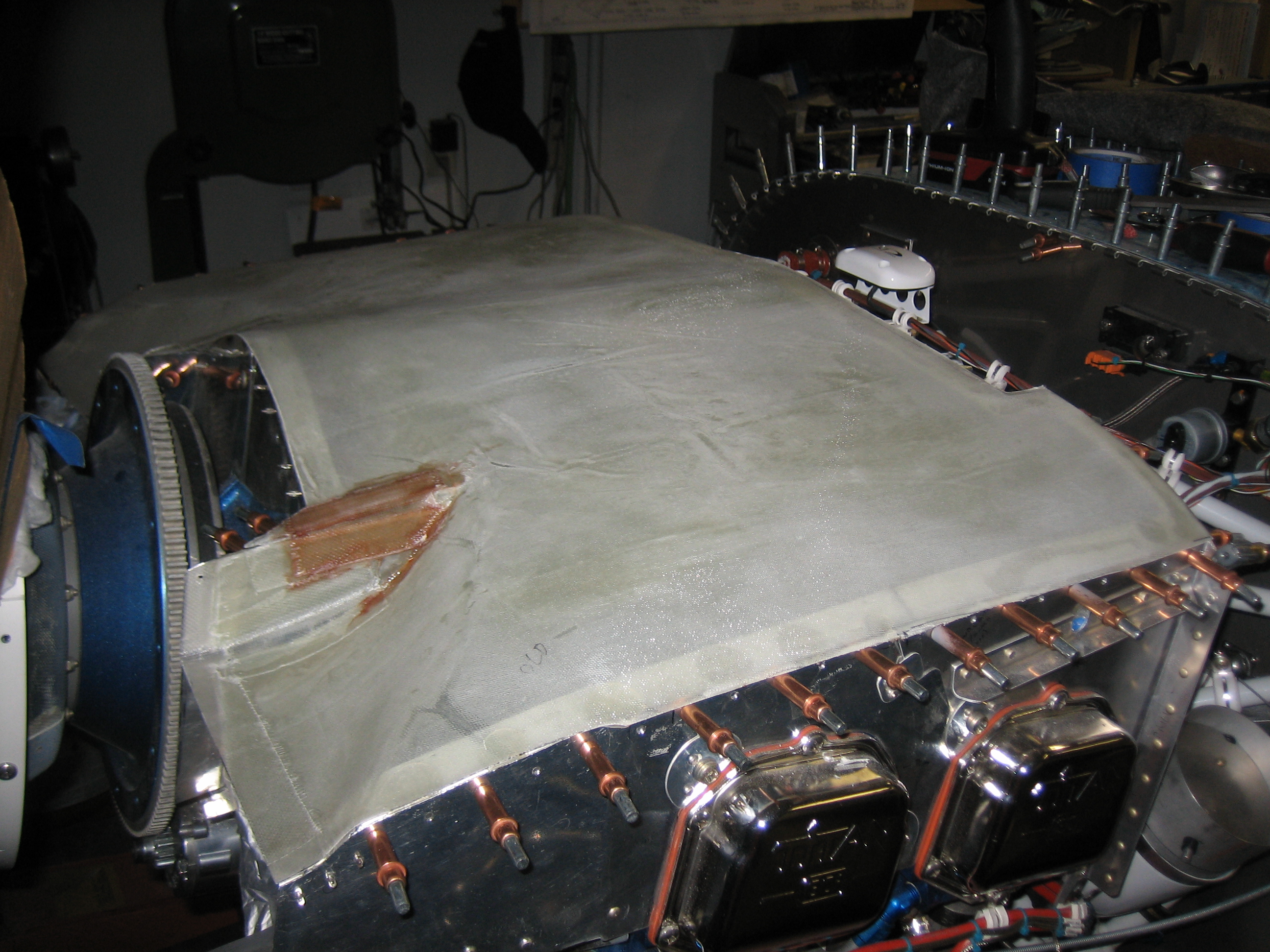
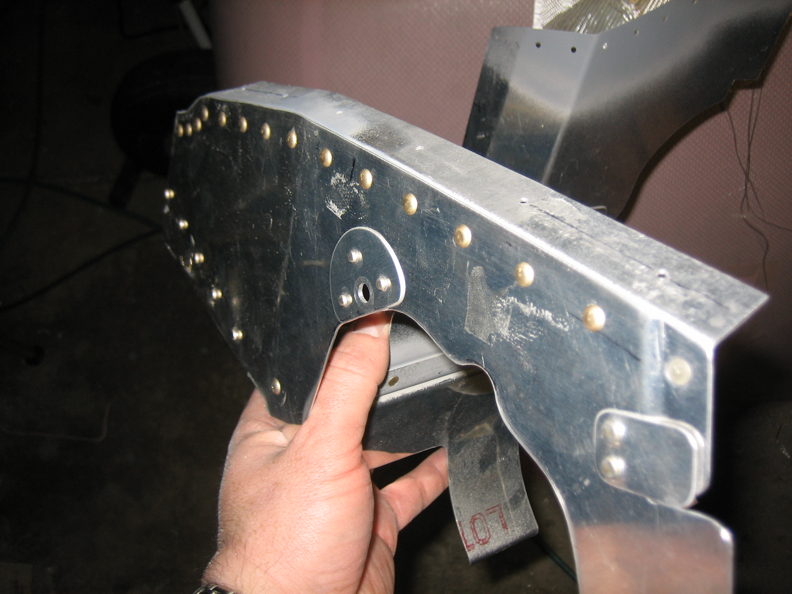
I cut a piece of baffle seal material to fit to the lower left cowl inlet and cut screw holes in it.

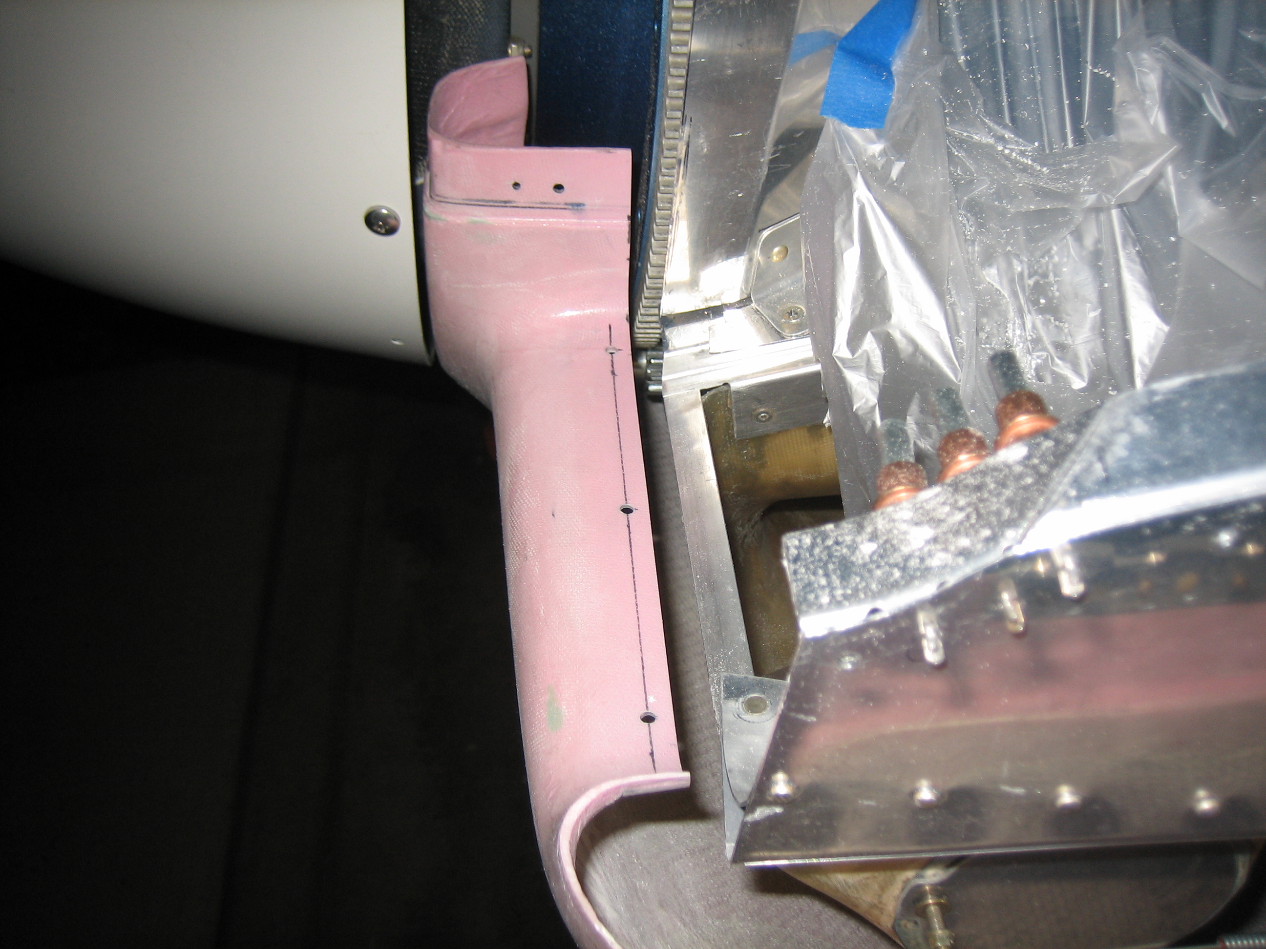
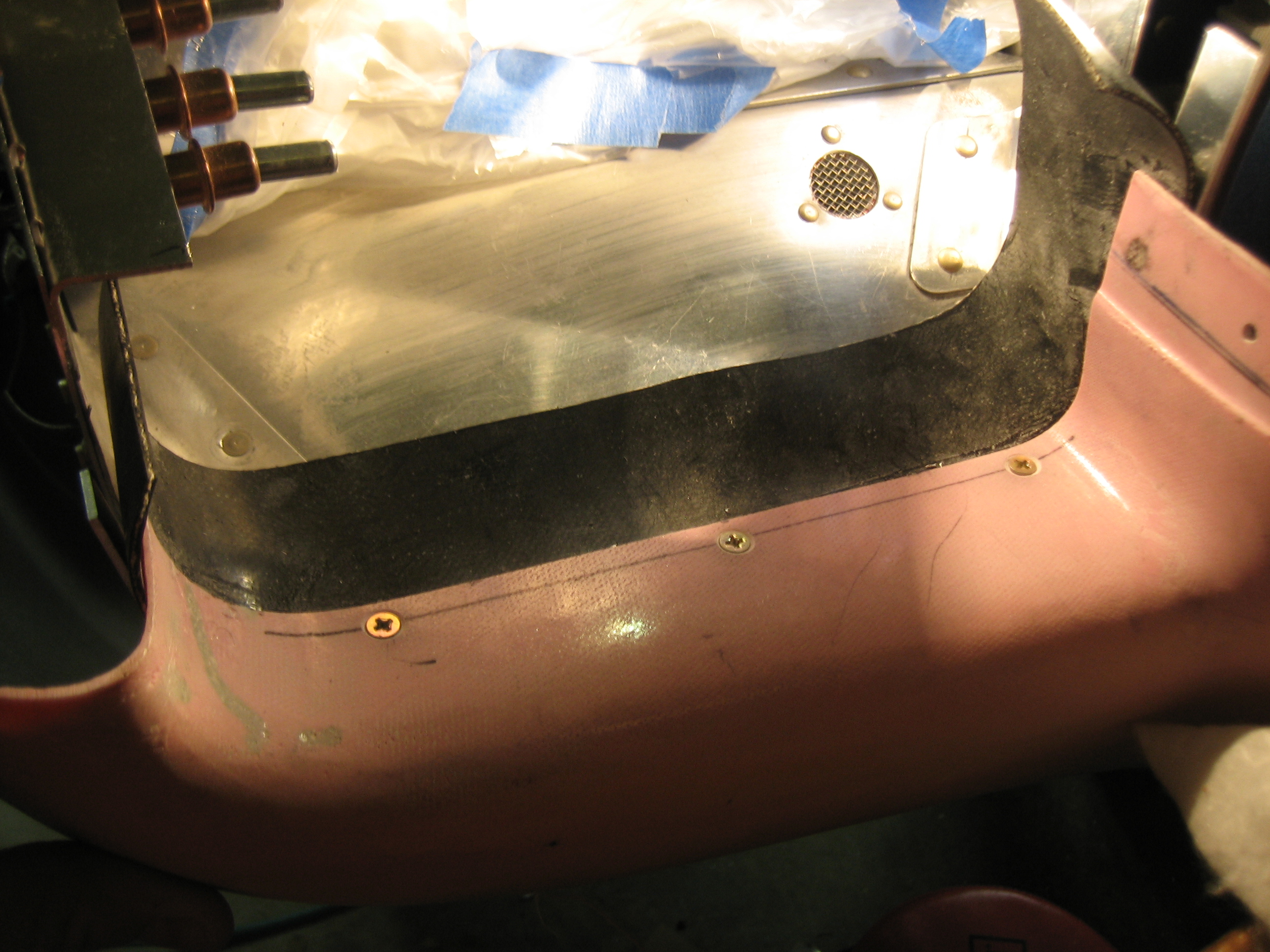
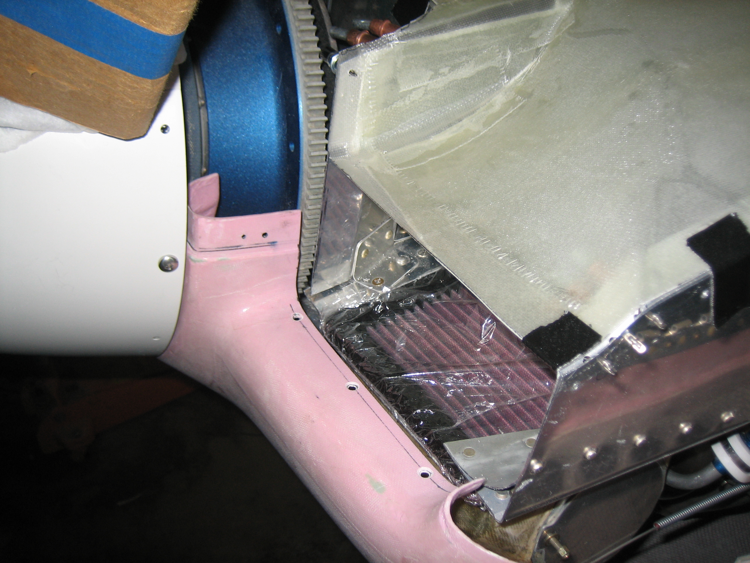
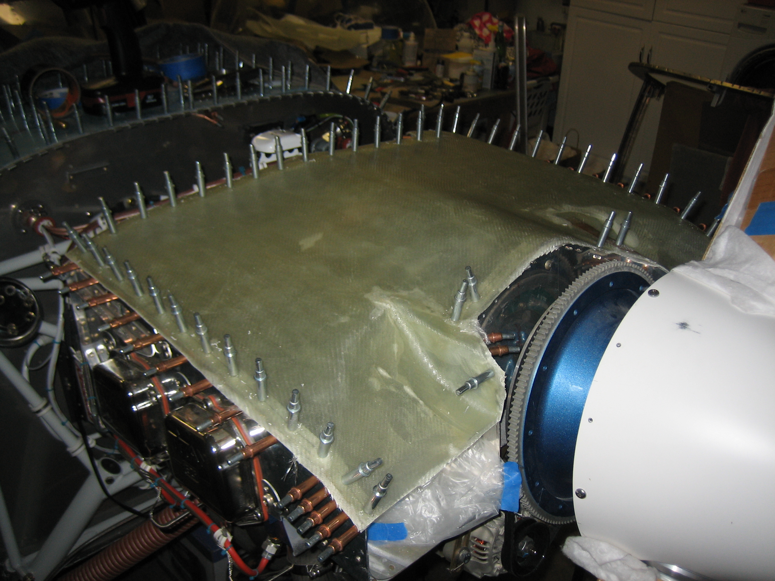
After attaching the baffle strip to the cowl inlet, I reinstalled the lower cowl to check the fit.  The baffle seal is cut back through the middle to expose the entire air filter, but goes back a little farther around the baffles to provide a little more overlap.

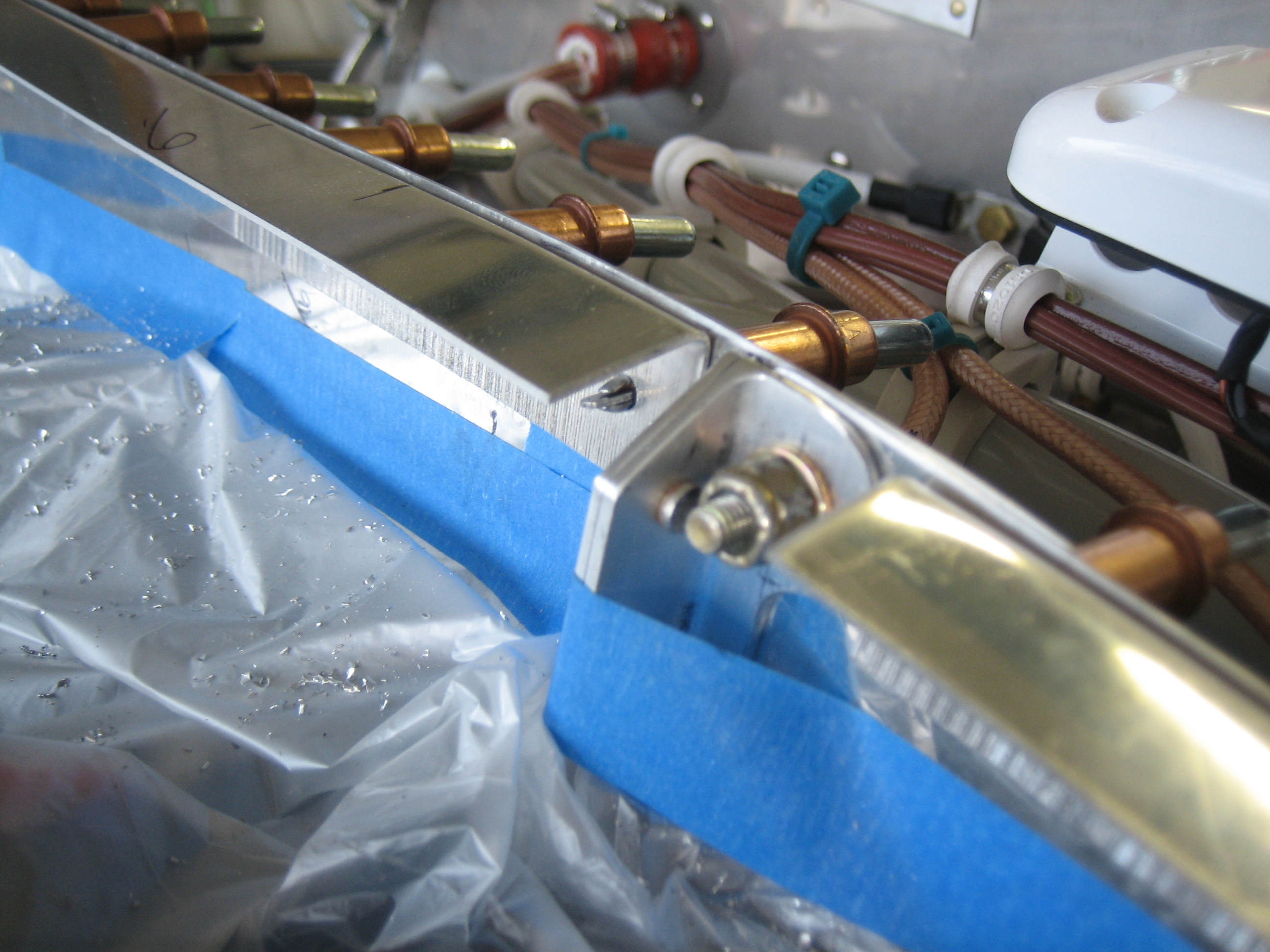
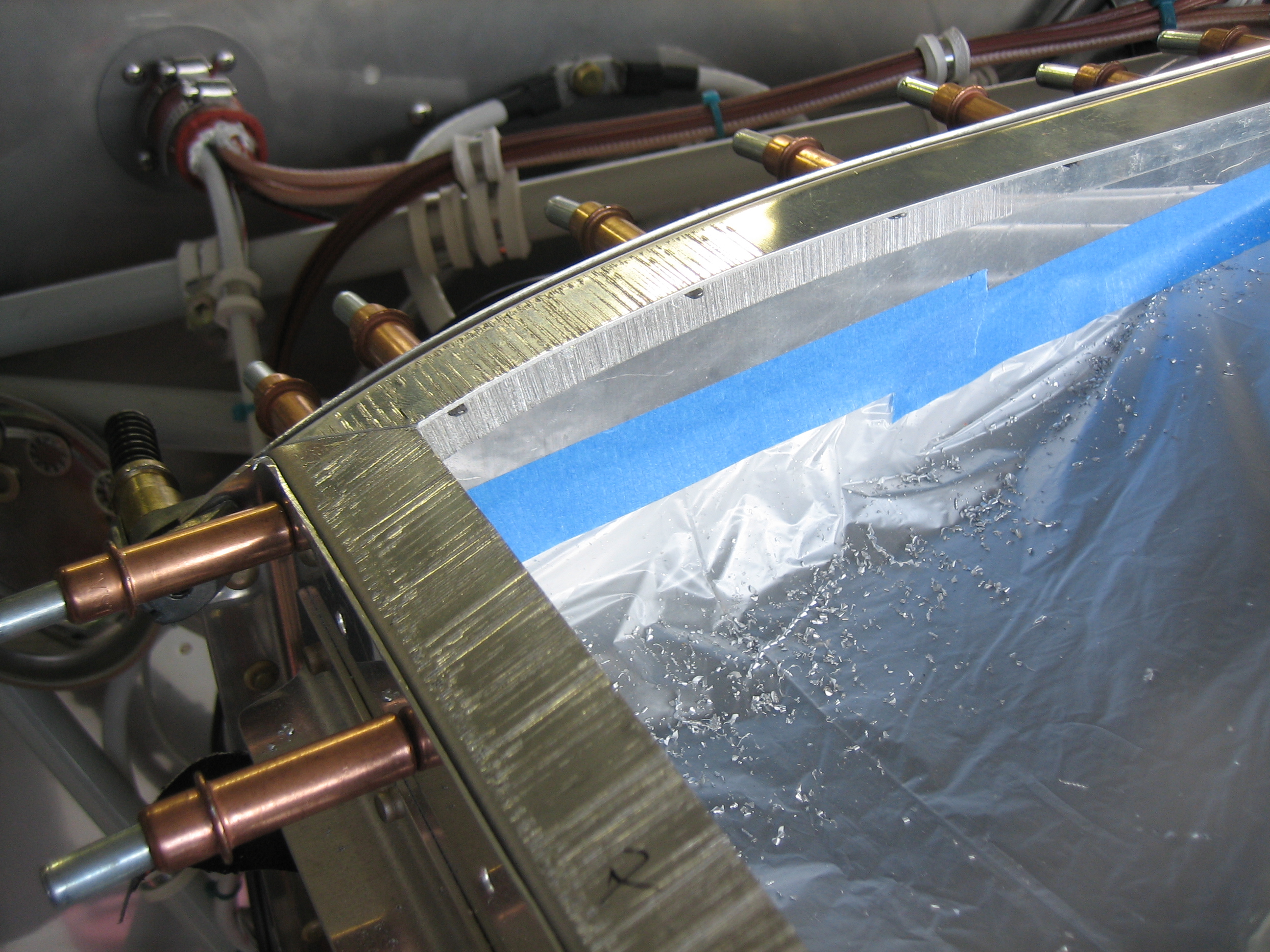
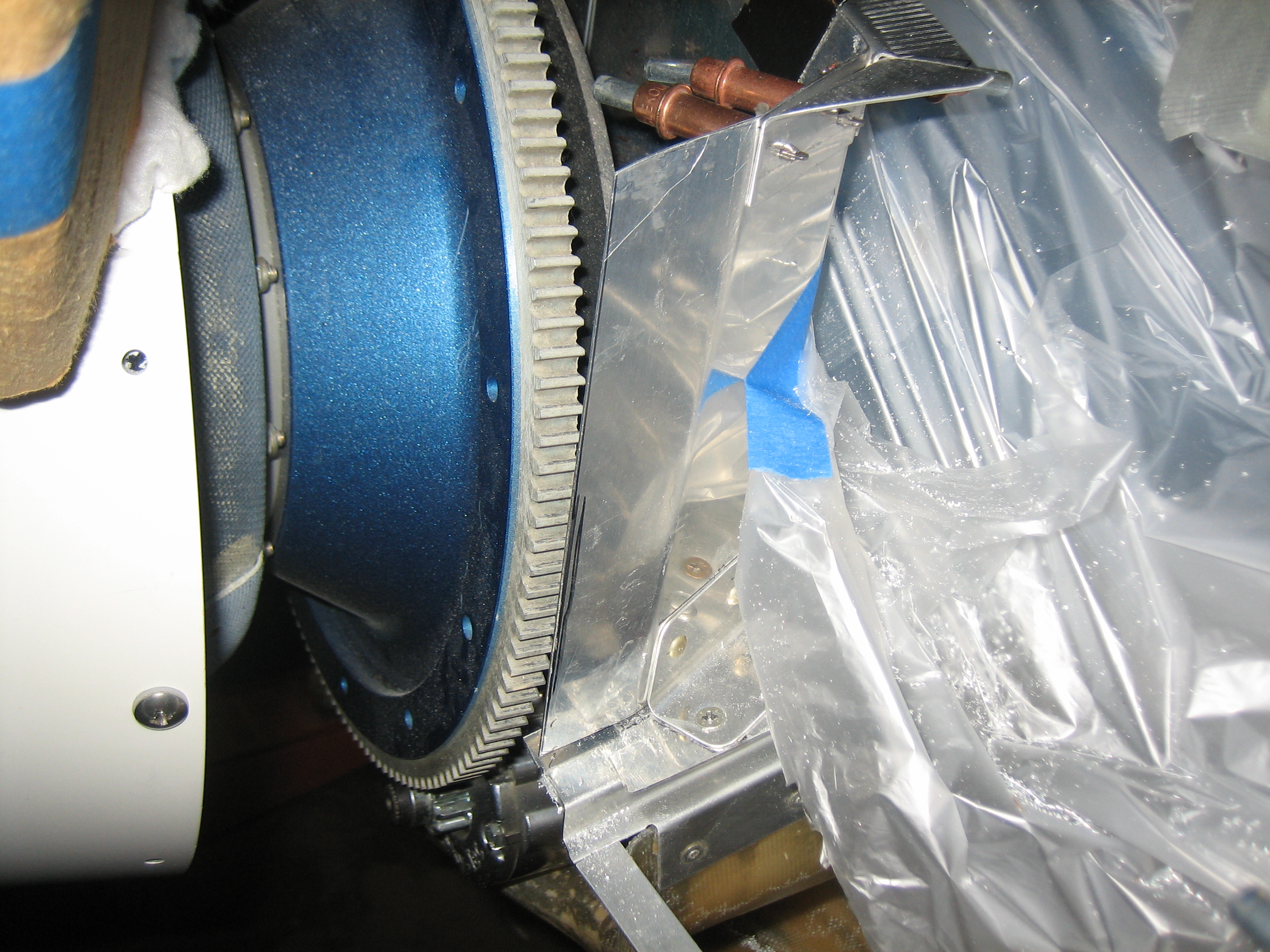
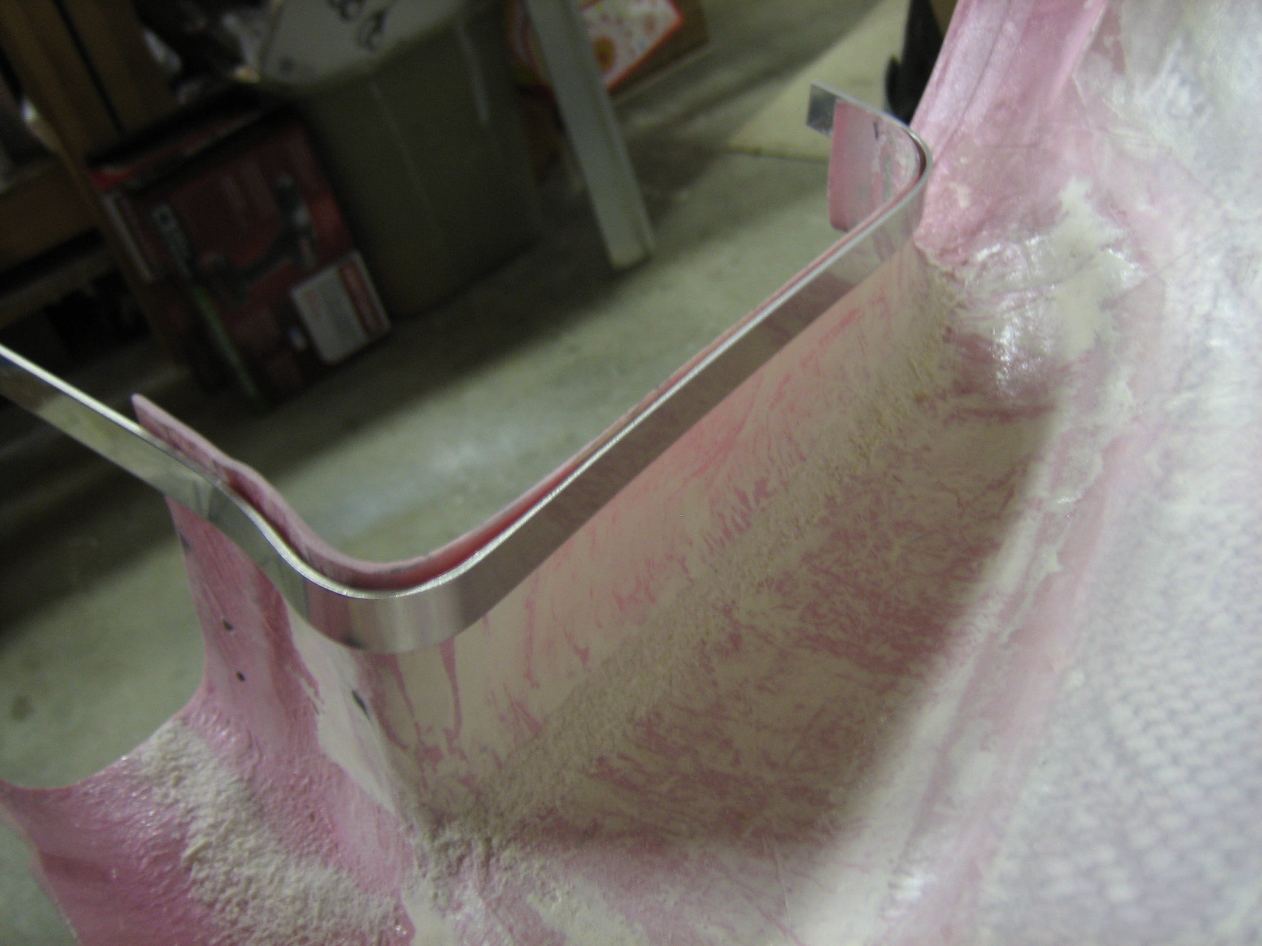
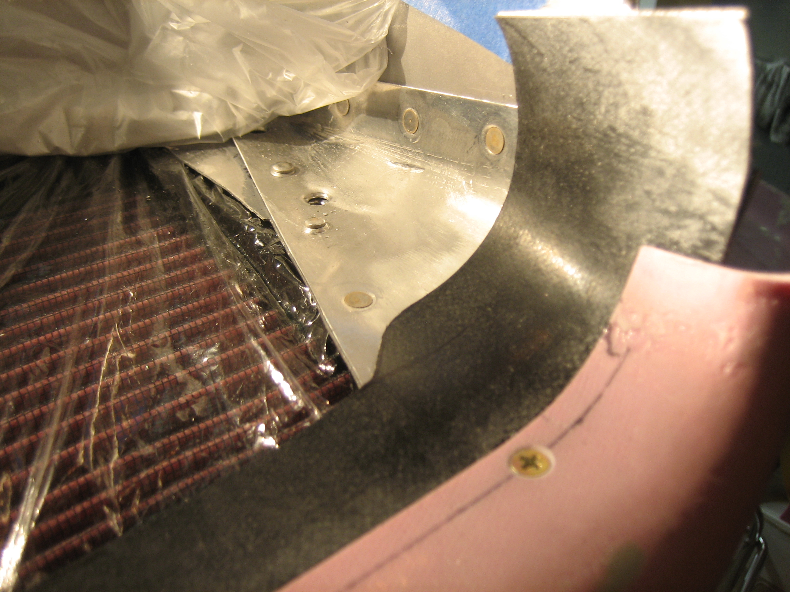
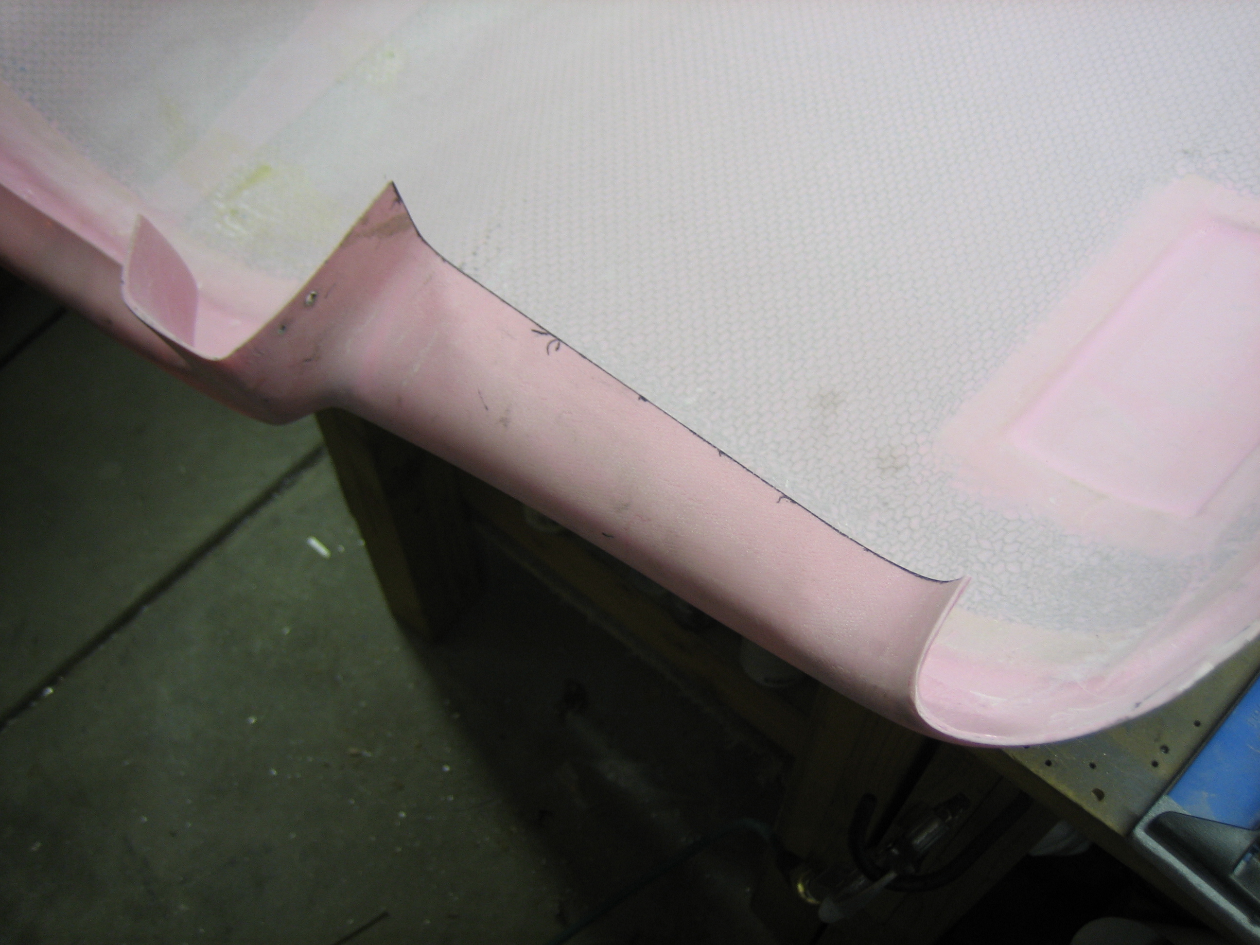
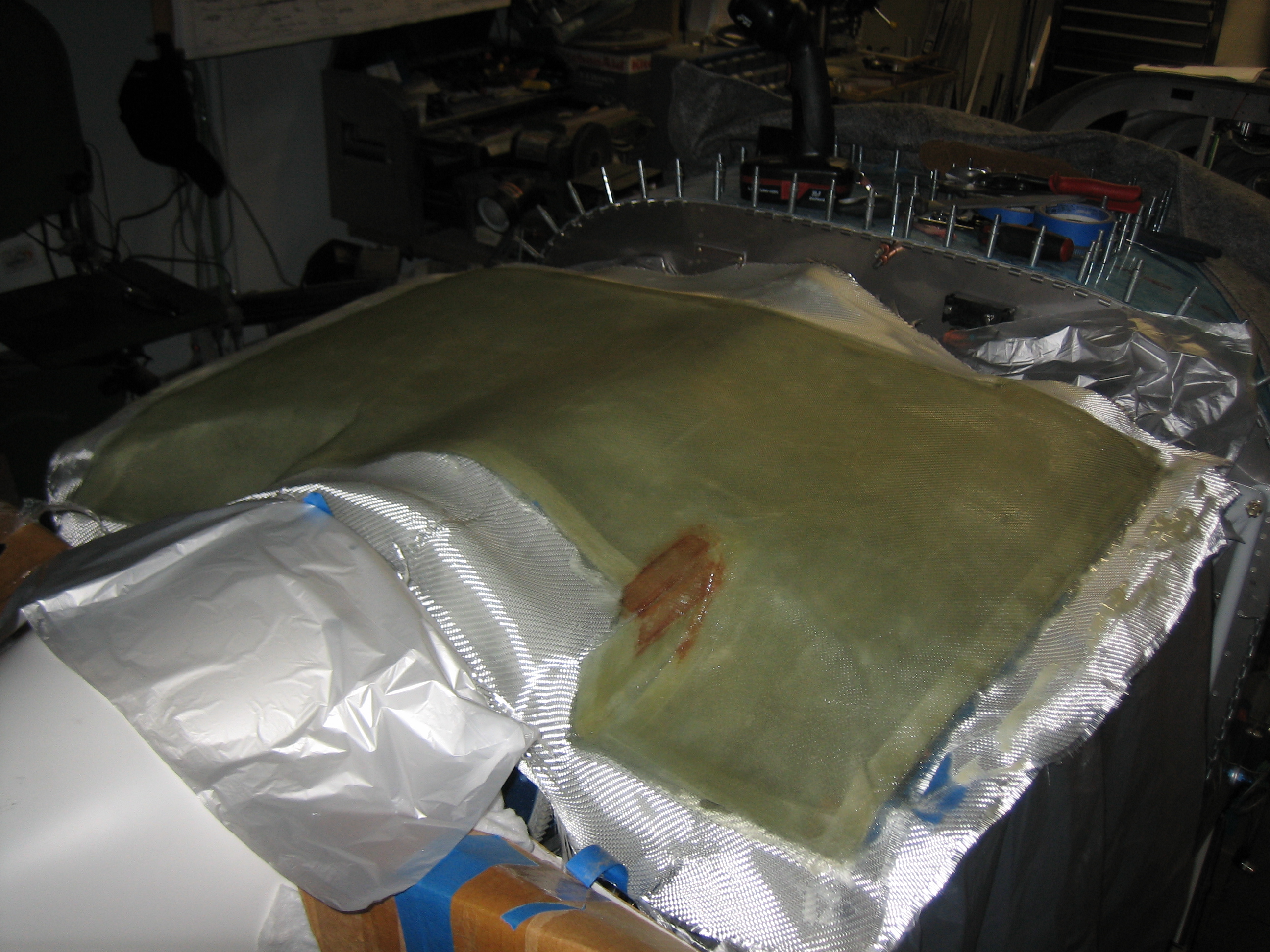
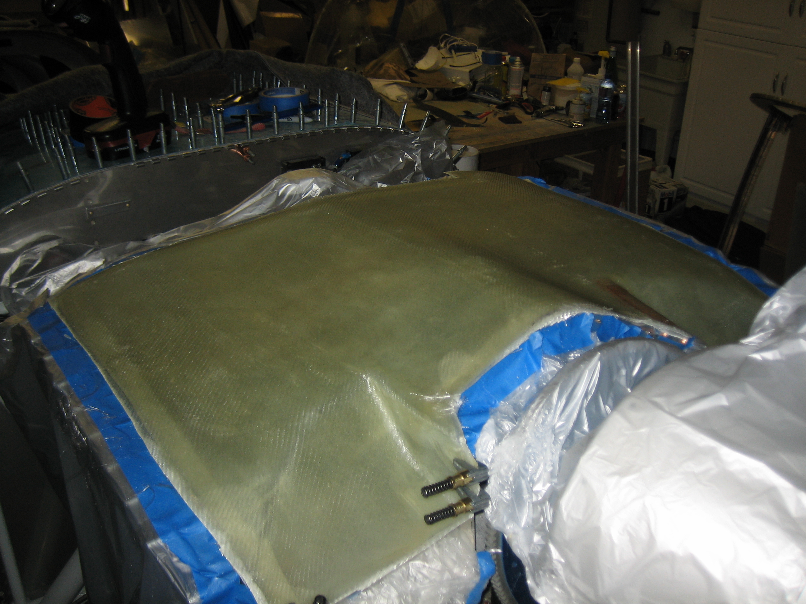
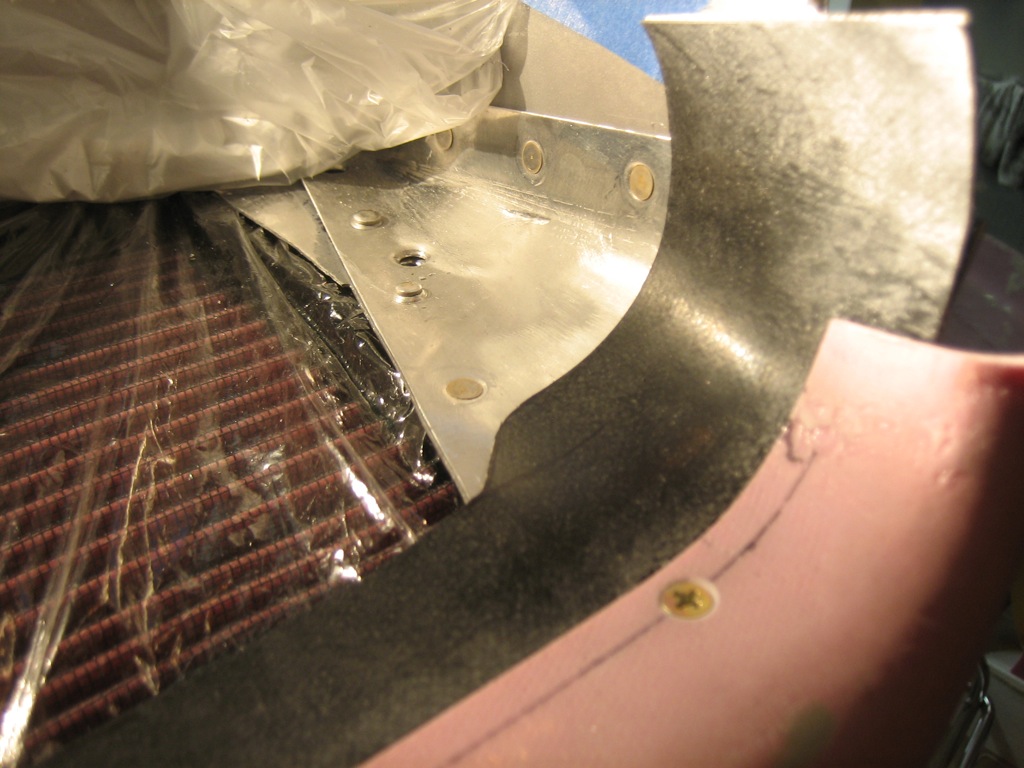
Here’s a shot of the outside edge of the inlet showing how the baffle seal material follows the conical gusset.

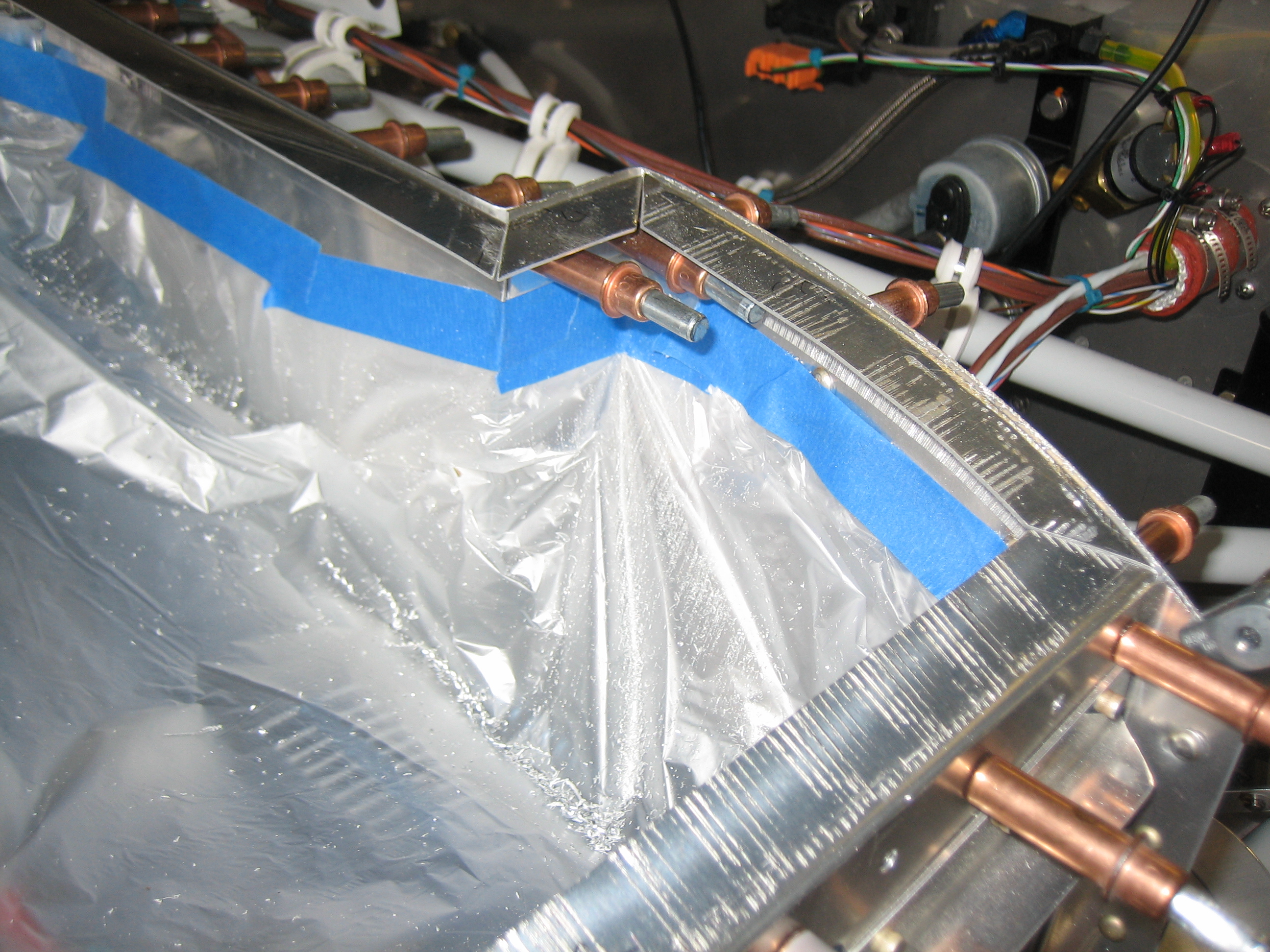
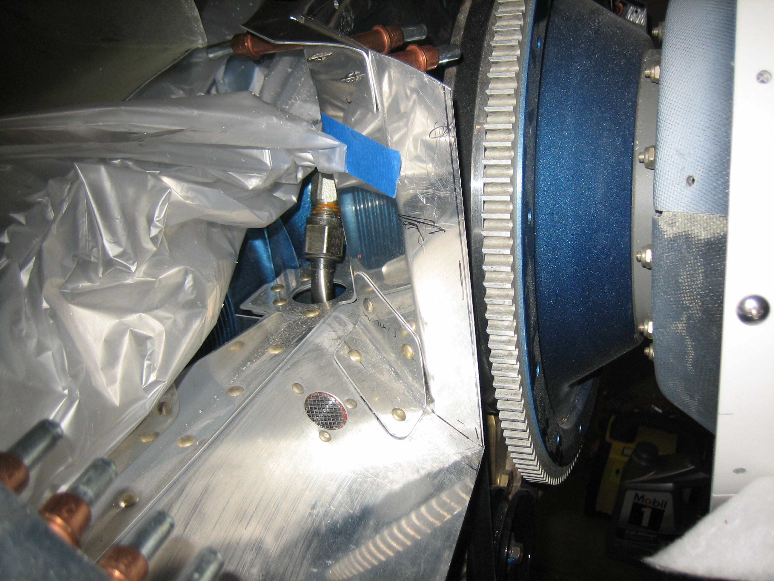
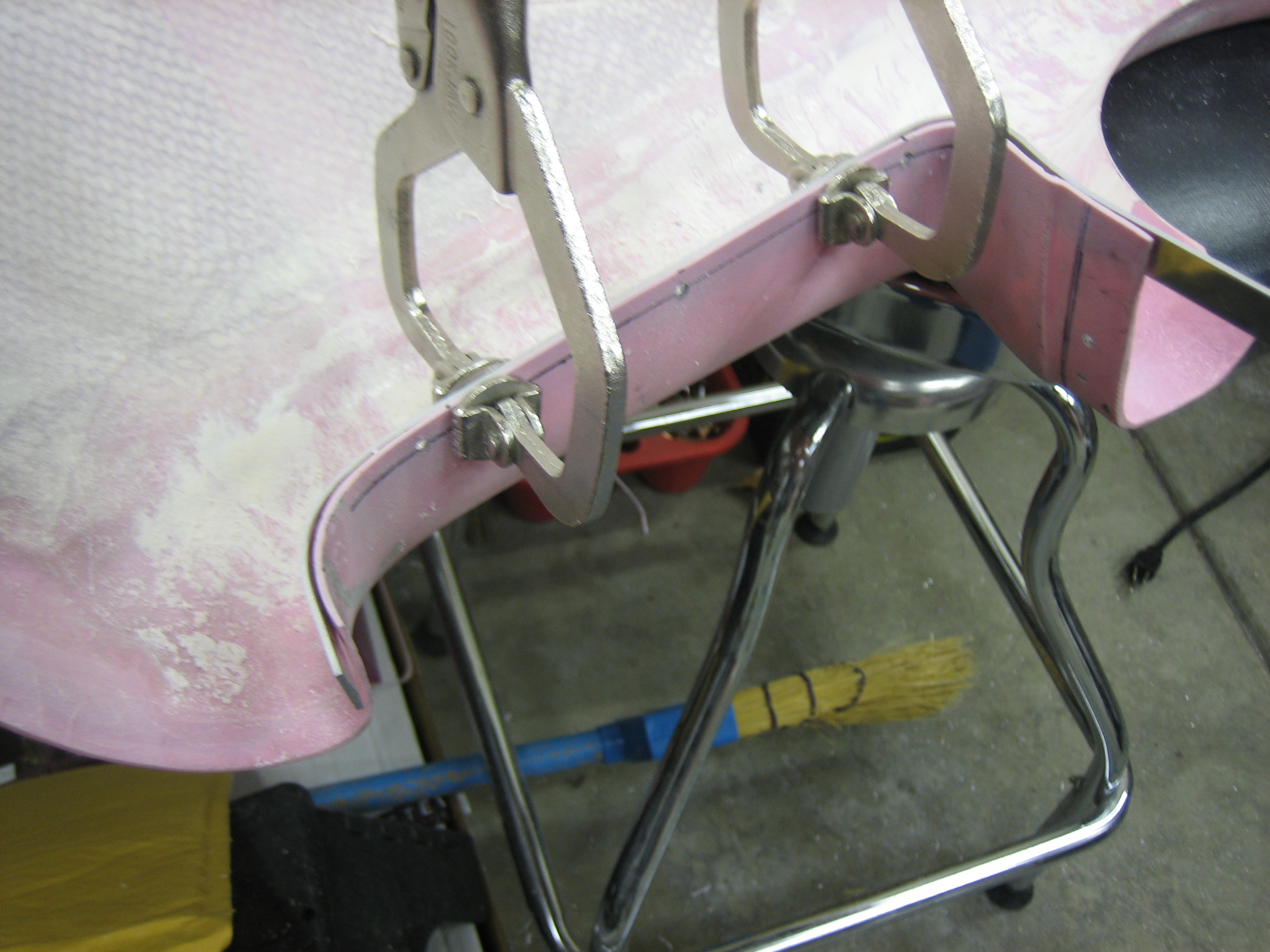
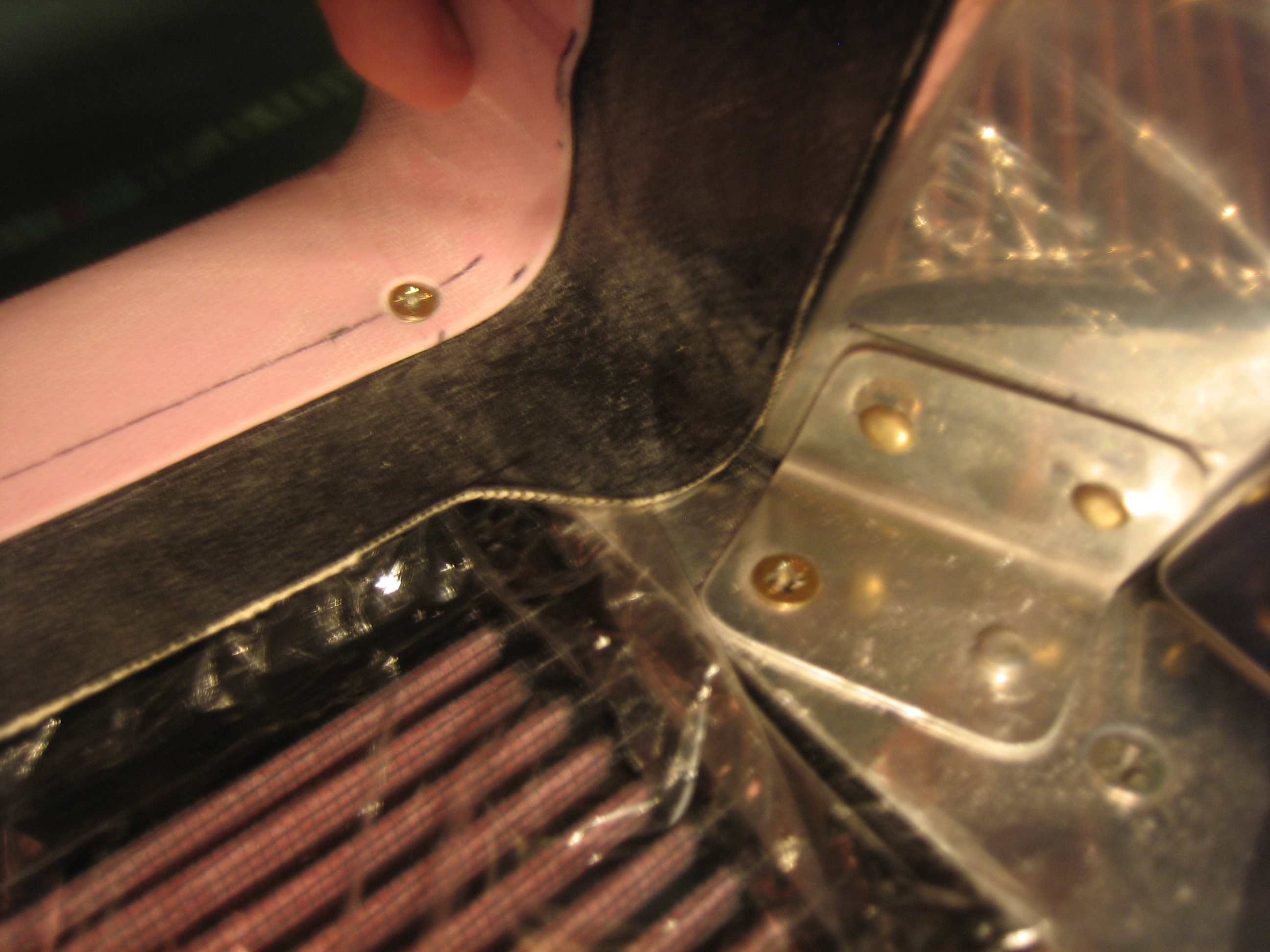
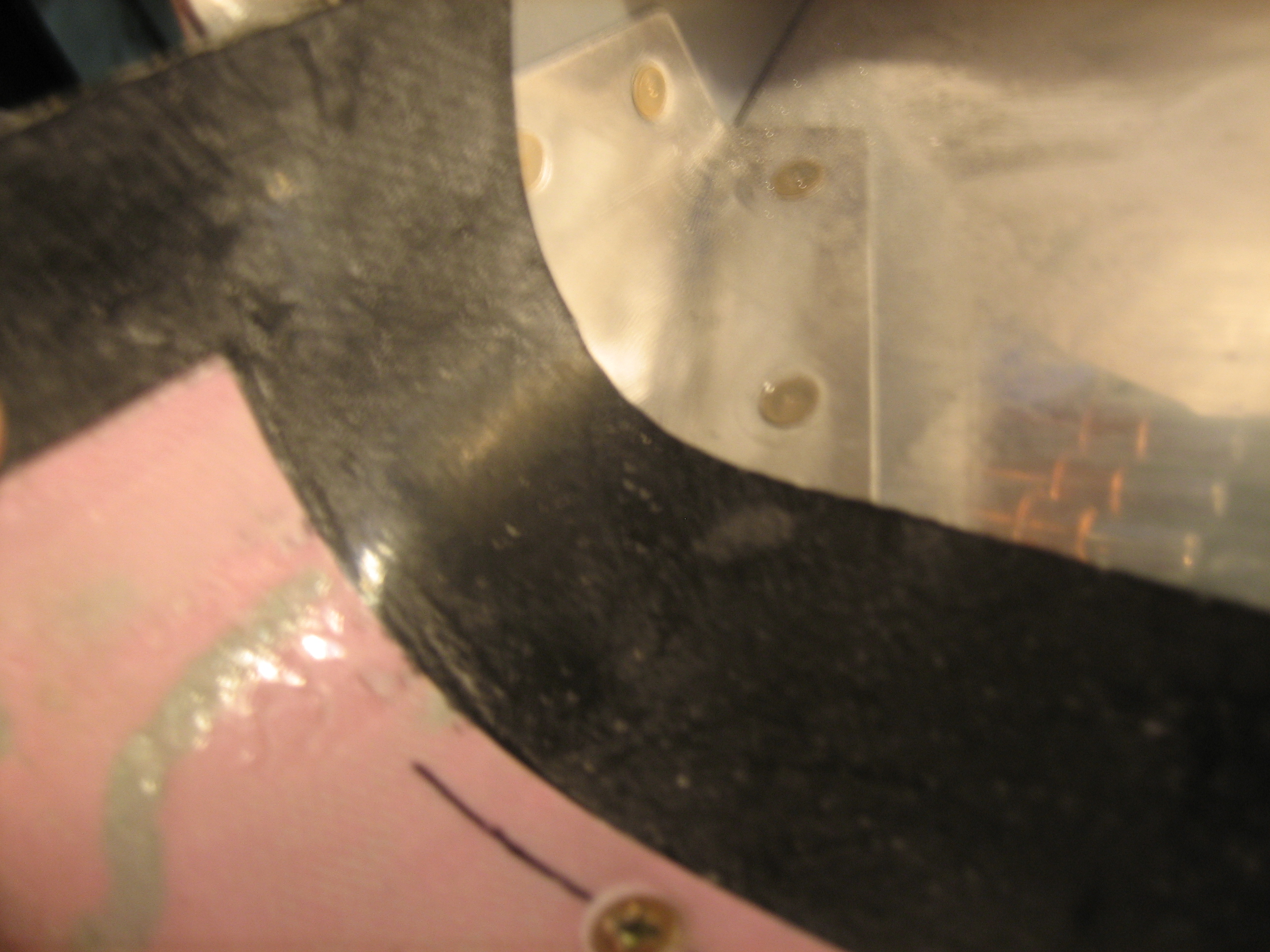
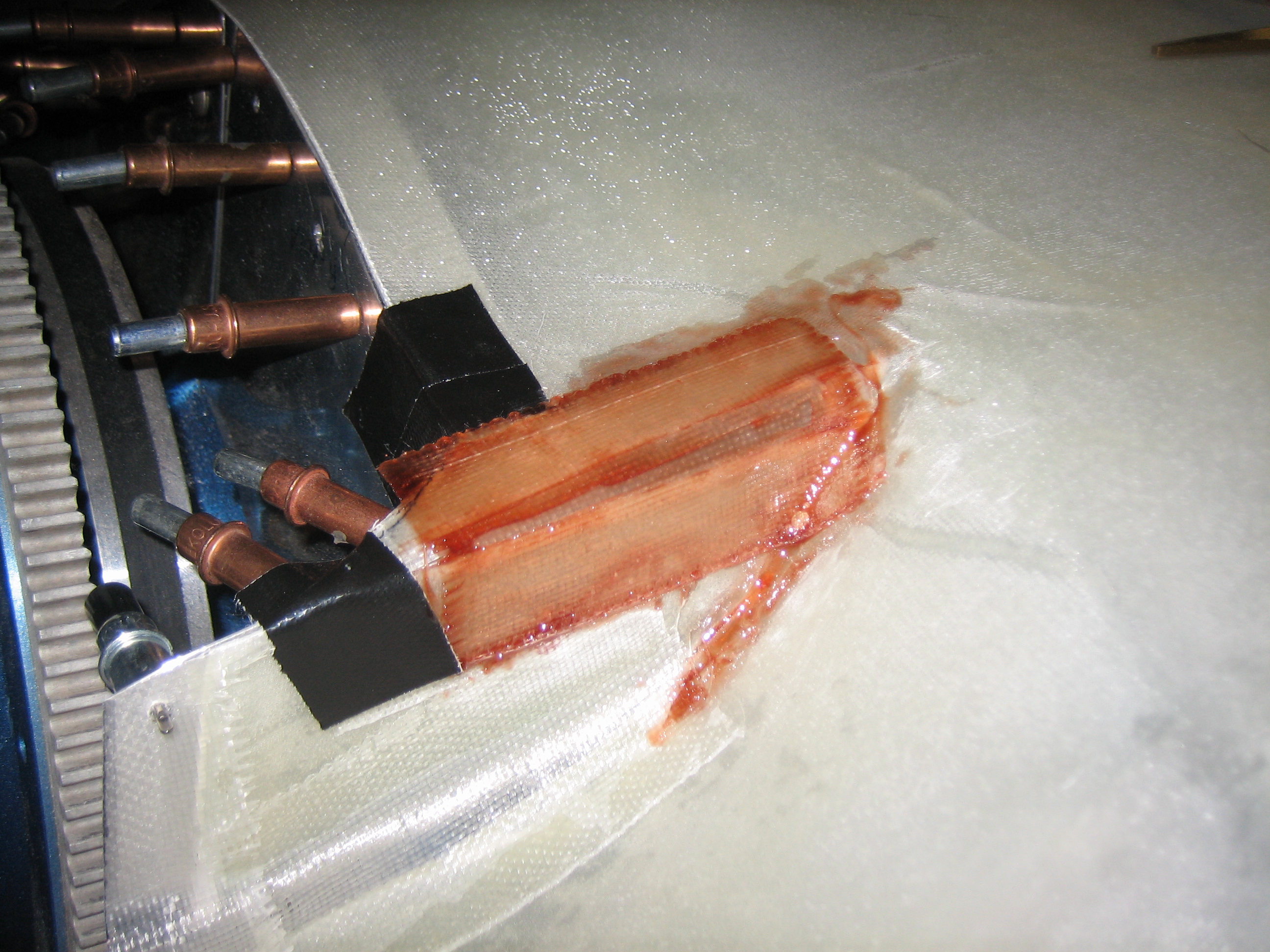
On the inside edge of the inlet, the baffle seal makes a sharp turn to tuck into the corner between the floor and wall of the baffles.

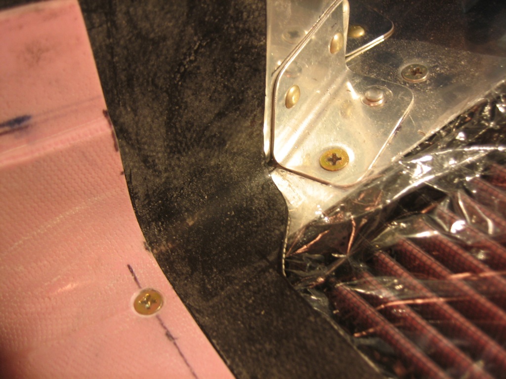
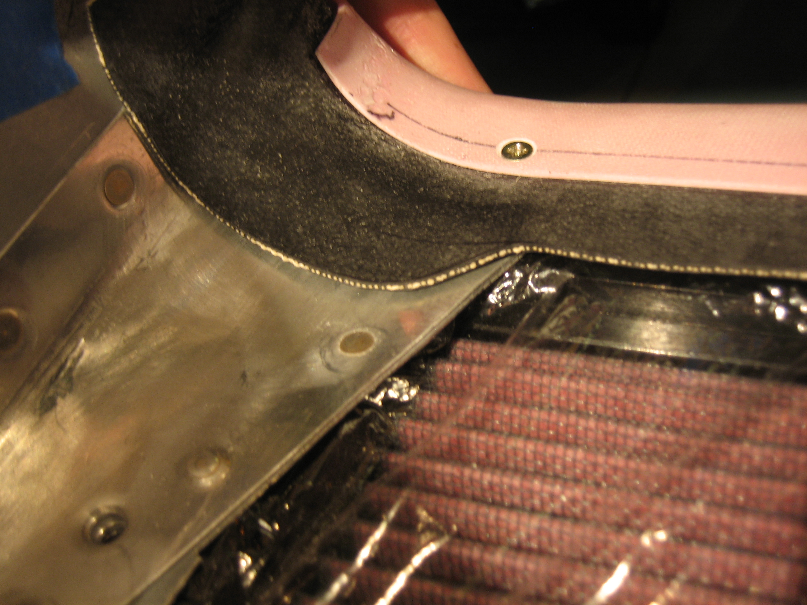
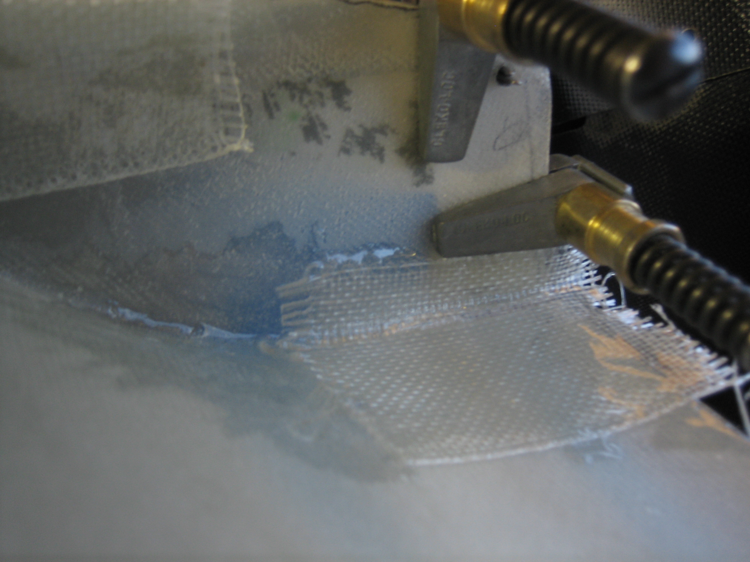
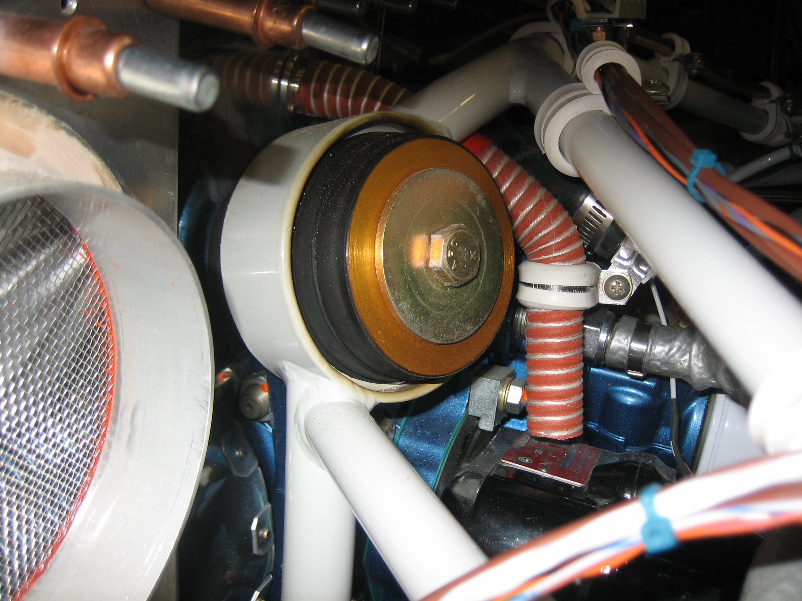
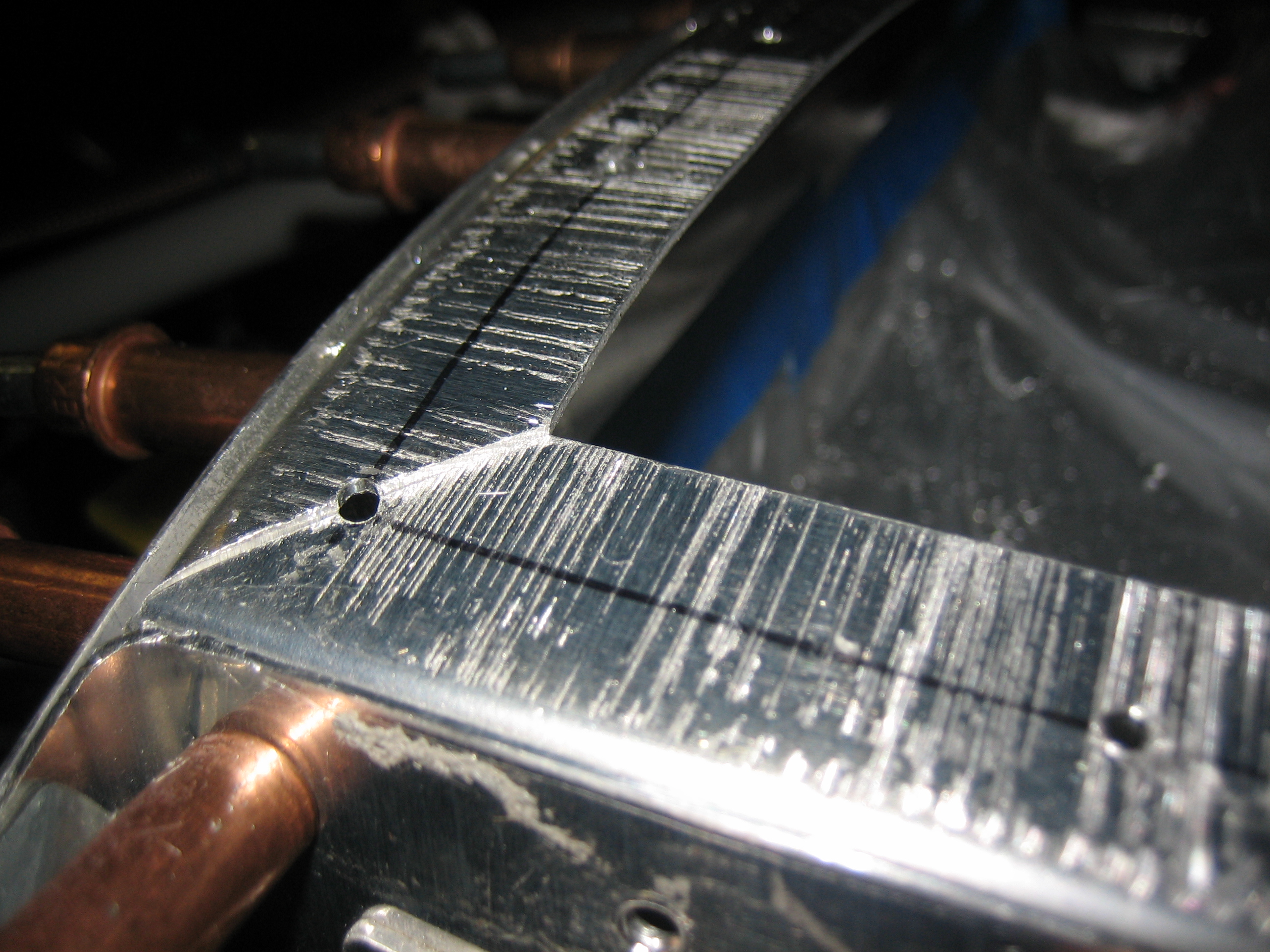
Here’s a shot looking forward showing how nicely the baffle seal material tucks into the corner.  There will be some RTV silicone sealing the gaps between the floor and the wall, so I’ll probably make a little fillet here to prevent air from leaking through the gap.  You might think I’m being anal about sealing every little gap (and I am), but any air that comes in the cowl inlets and isn’t used for cooling is unnecessary drag.

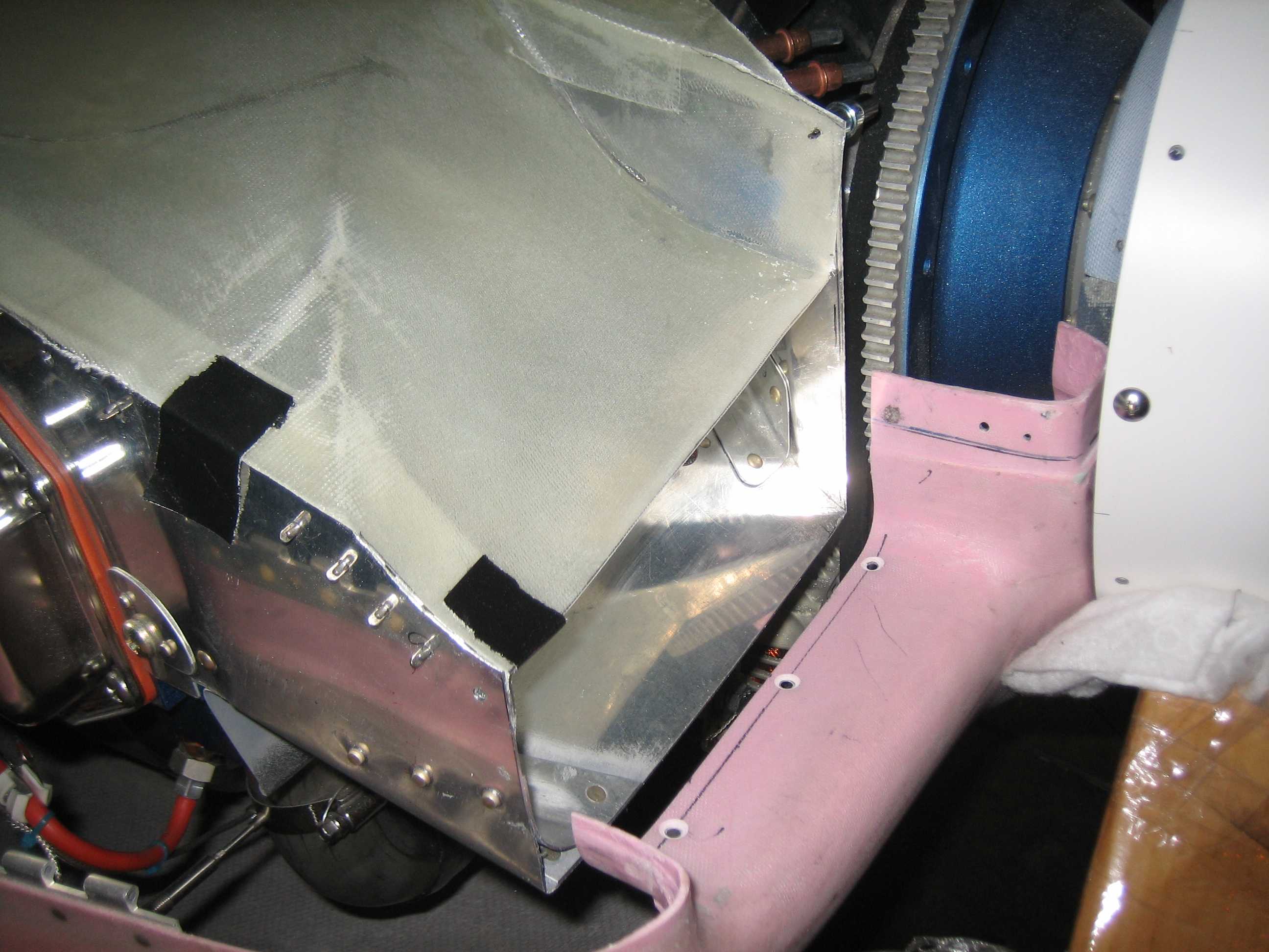
This is looking forward at the outer edge of the inlet at the conical gusset.  You can see that the baffle seal material lays down fairly well against the gusset.  Once the plane is flying and the engine heat warms this up, it will take a set and should lay down nice and tight.

Fit Lower Right Cowl Inlet Baffle Seal

I fit the lower right cowl inlet baffle seal tonight.  This went a lot faster than the other side.

Just like the other side, the baffle seal material follows the curvature of the conical gusset nicely.

Here’s the shape of the seal material.  It’s shaped a little different than the other side because the ramp is much steeper on the right side.

Worked on Plenum and Upper Cowl

I reinstalled the plenum and adjusted the inlet height so that there’s just enough room for the upper baffle seal material.  You can see a small cleco holding this in position just behind the flywheel gear.  I then trimmed the plenum back flush with the baffles.

Here’s the other side.

I then trimmed back the upper cowl inlet so that it’s flush with the lower cowl inlet and 3/8″ back from the forward edge of the plenum.

The left side of the plenum needed one more adjustment so that it lays flush with the mounting angles.  I cut the plenum and laid up a small piece of glass over the joint to tie it back together.

Laid Up Additional Glass on Plenum

I made one last little tweak to the plenum to get the inner edge of the right inlet to lay flush against the baffles.  I used some 5 minute epoxy so that it would be cured enough to do the rest of the layups later in the day.

While I was waiting for that to cure, I installed the blast tube for the magneto.  It’s anchored to the breather tube and is sitting about 1/4″ above the mag.

In preparation for doing the additional layups, I hot-glued the plenum down to the mounting angles.

I then laid up three layers of 9 oz glass using the high-temp epoxy.  I’ll see how stiff this is tomorrow and will add a layer of carbon fiber if it’s not stiff enough.

Prepped Plenum for Mounting

I popped the plenum off the mounting angles (releasing the hot glue I had used to attach it).  I then trimmed most of the excess glass off of the edges.

I then laid out and drilled pilot holes for all of the attach screws that will attach the plenum.  I put holes at all of the corners and will use nutplates that span the joints.

Drilled Plenum and Started Riveting Mounting Angles

I drilled the plenum to the mounting angles through the holes I drilled in them yesterday.  I shined a light through the plenum so that I could see the holes.  They’re only drilled out to #40 now, but I’ll open them up for #8 screws once the mounting angles are riveted and I know everything is in it’s final location.  The spacing varies somewhat around the perimeter based on the length of the various mounting angles, but they’re predominantly between 1 5/8″ and 1 7/8″.  They’re tighter at the front outside corners where the plenum turns sharply downward.

I pulled the plenum and baffles off so that I could rivet the mounting angles to the baffles.  The engine hasn’t been this naked in a very long time.

I started cleaning up and riveting the mounting angles to the baffles.  The mounting angles need quite a bit of time with the deburring disks on the die grinder due to the fairly deep marks put in them by the shrinker/stretch dies.  Notice that the aft rivet (on the far right in this picture is flush on the outside because the #4 cylinder baffle tucks in here.

Routed Wing Wiring Outside of Fuselage, Replaced Oil Drain

I drilled holes in the sides of the fuselage for the wing wire runs and fished them through along with a grommet.  To keep the wires out of the way, I coiled them up and tucked them back into the aileron push-rod hole.

The wing tip wiring will go straight into the wing wiring conduit from the hole I drilled, but the roll servo cable turns forward from there and then needs to go up to a hole near the top of the wing to route down to the servo.  I pop-riveted a wire clamp to the side of the fuselage to anchor the cable and keep it away from the aileron pushrod.

I also received the Dynon ADS-B receiver today and spent some time deciding where to mount it.  There’s basically no place up front that is easily accessible since I’m trying to make sure that every box in the plane can be accessed and removed if necessary.  I ended up deciding to order one of Van’s ELT mounts that fits between the left side stringers and mount it there.  It’s a fairly short run of coax from there back to where the UAT antenna will be mounted about 2′ behind the transponder antenna.

I decided to replace the Curtis quick drain on the right that came with my engine with the one from Saf-Air.  Not only is it better made, double sealed and rebuildable, but it’s 2 3/8 oz lighter!  That’s a huge weight savings for only $80.  There are other parts on the plane that I spent hours on trying to shave out less weight than this simple change.

Here’s the valve installed and safety-wired.