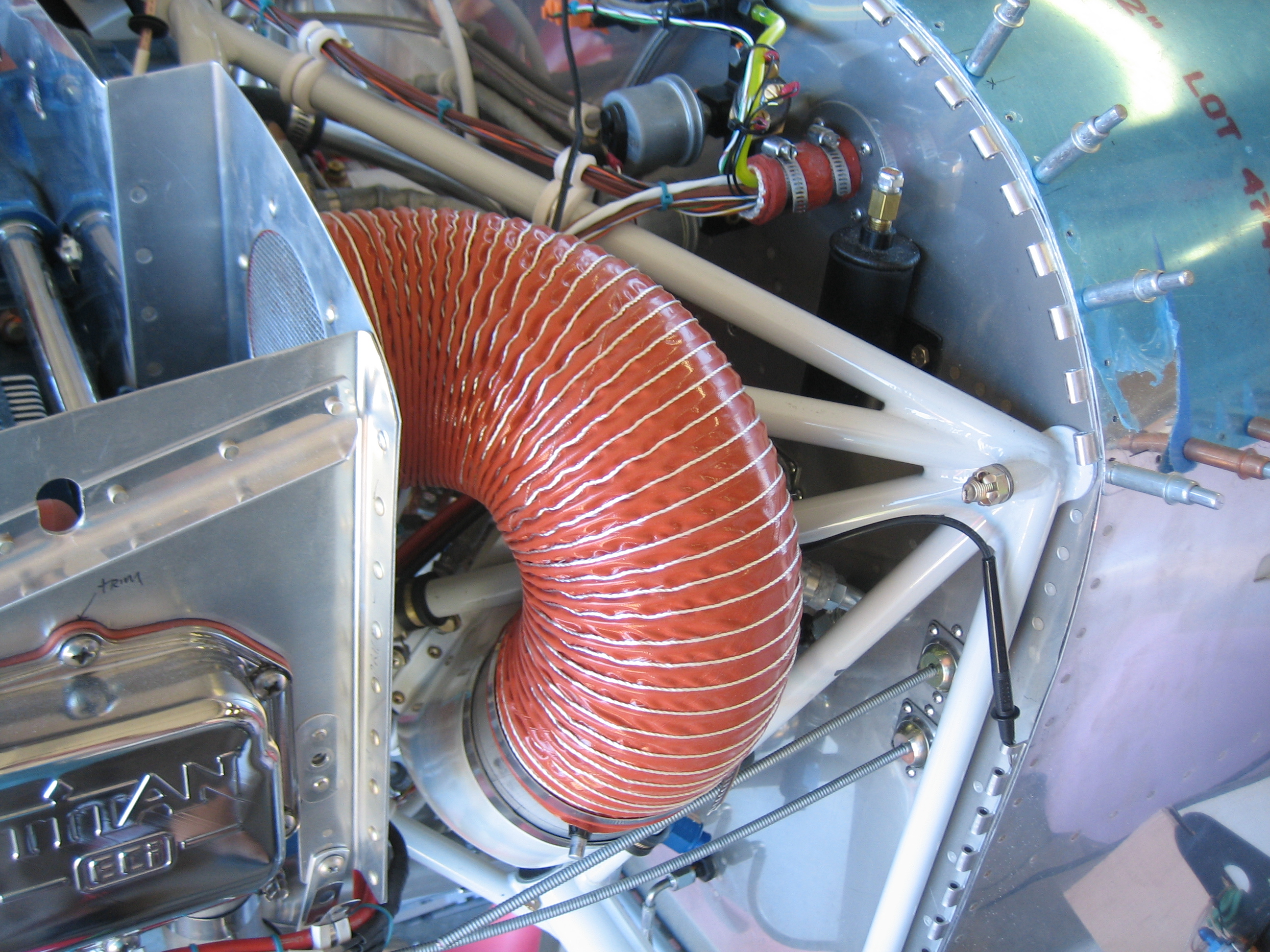
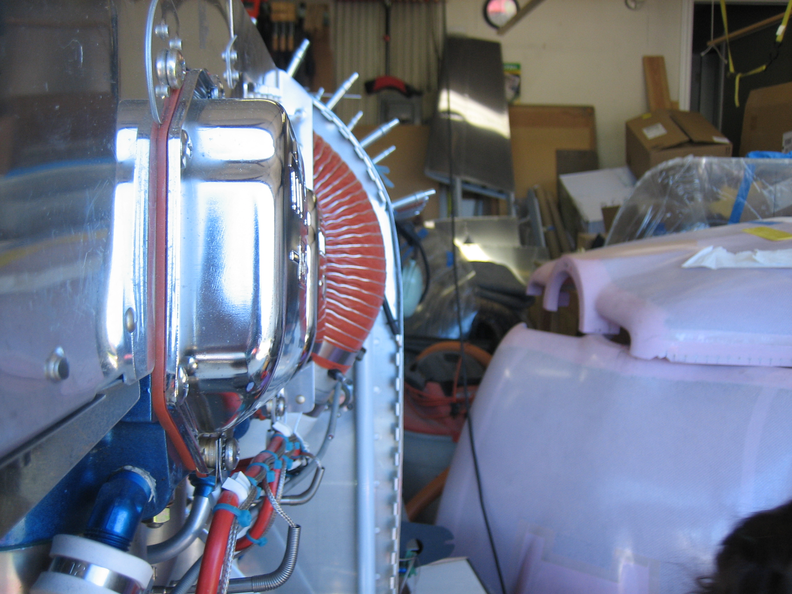
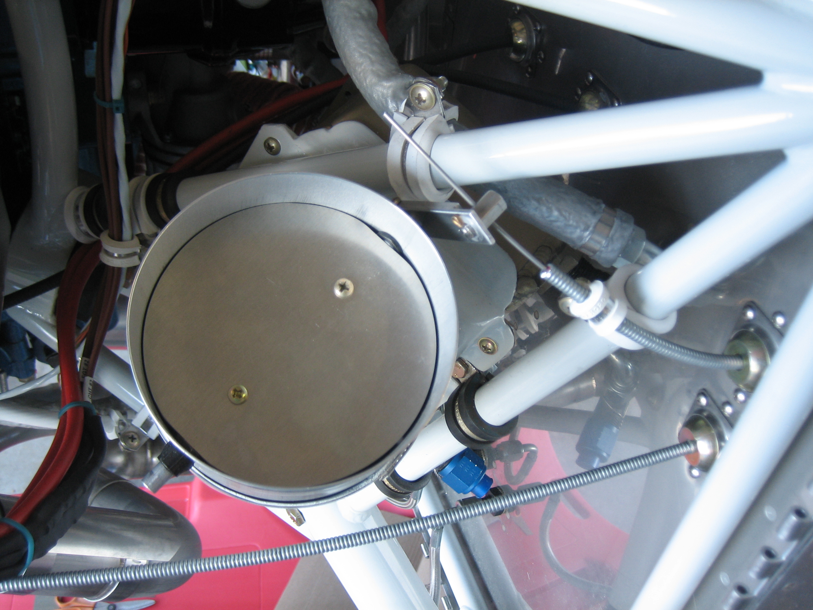
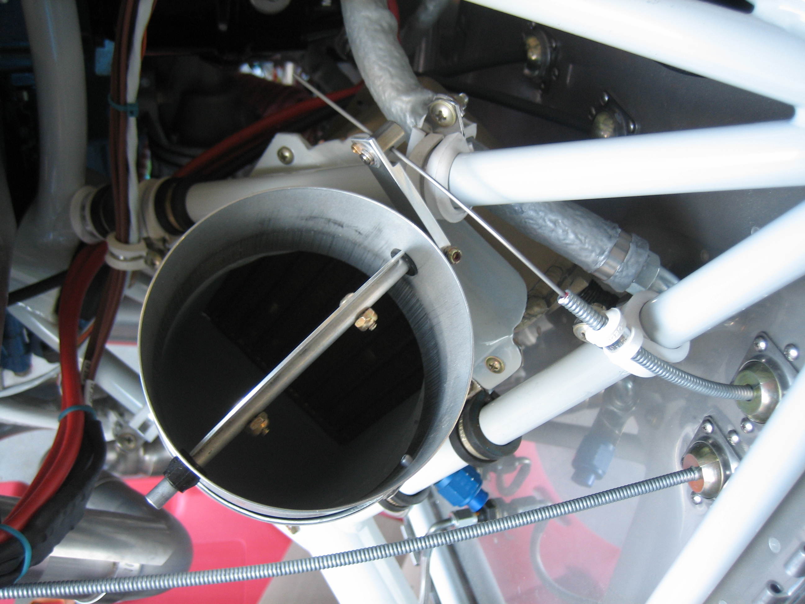
I trimmed down the 4″ SCAT tube so that it fits between the back of the baffles and the butterfly valve on the oil cooler plenum.
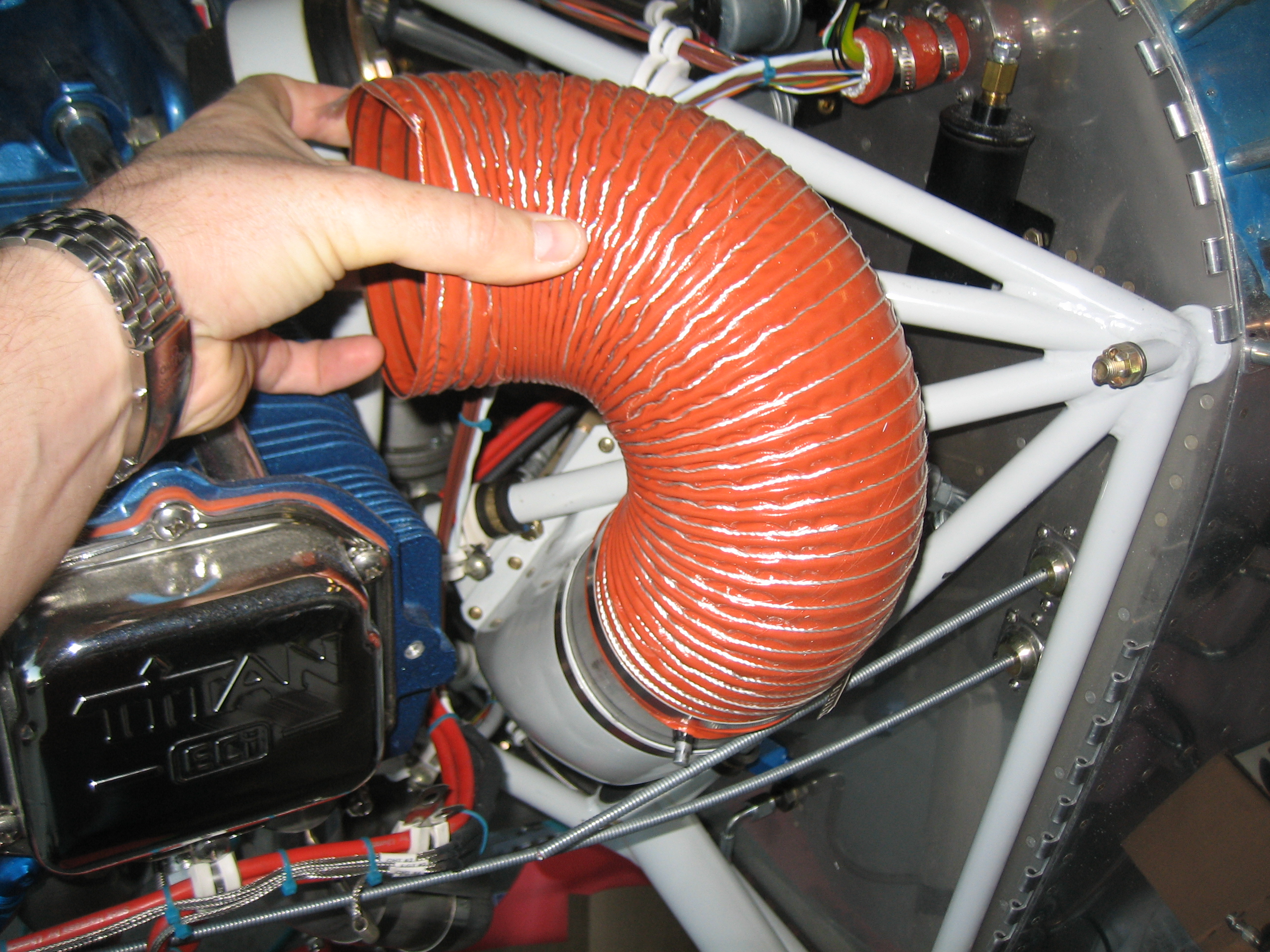

I trimmed down the 4″ SCAT tube so that it fits between the back of the baffles and the butterfly valve on the oil cooler plenum.
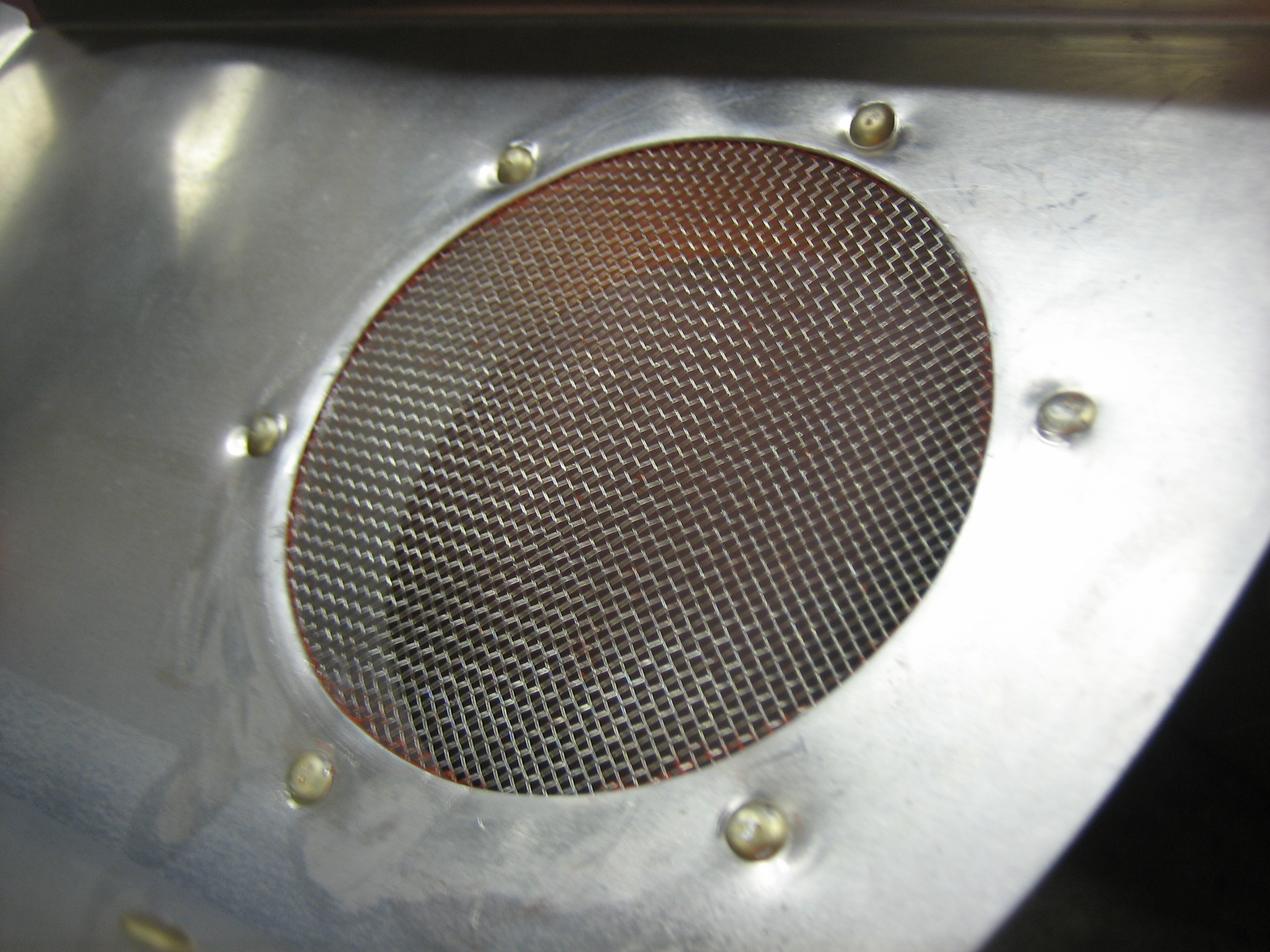
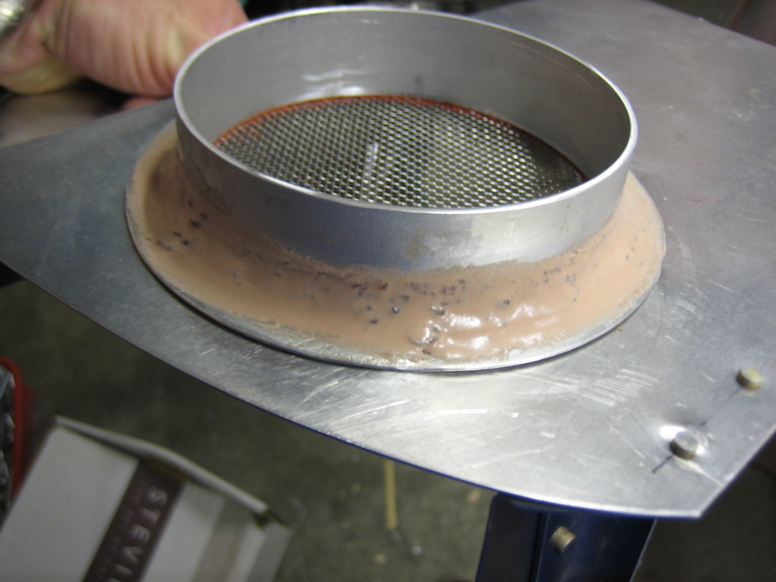
I cleaned up the hole and cut a piece of stainless steel screen to fit. I then riveted everything together with some RTV. Here’s the back side of the baffles where the SCAT tube will attach.
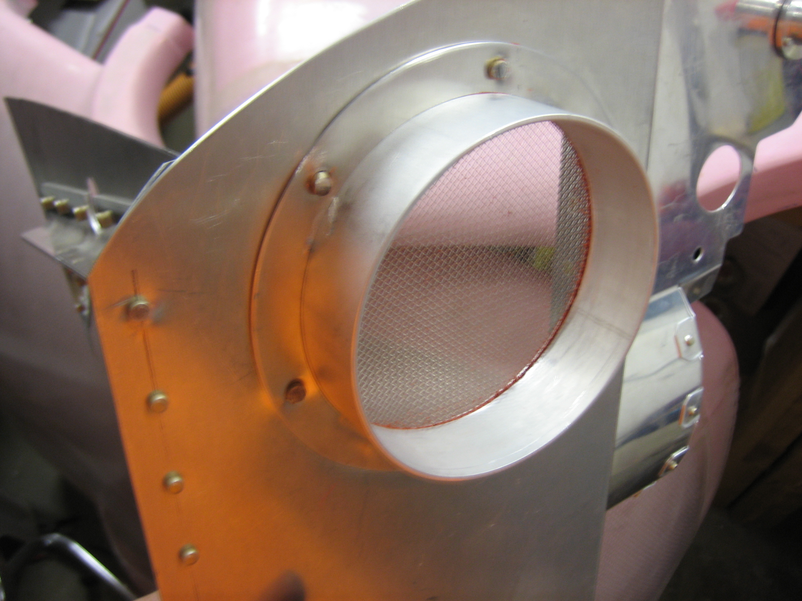
Here’s the front side and a better view of the screen. The metal around the rivets deformed a bit during riveting, but there’s not too much I can do about that.
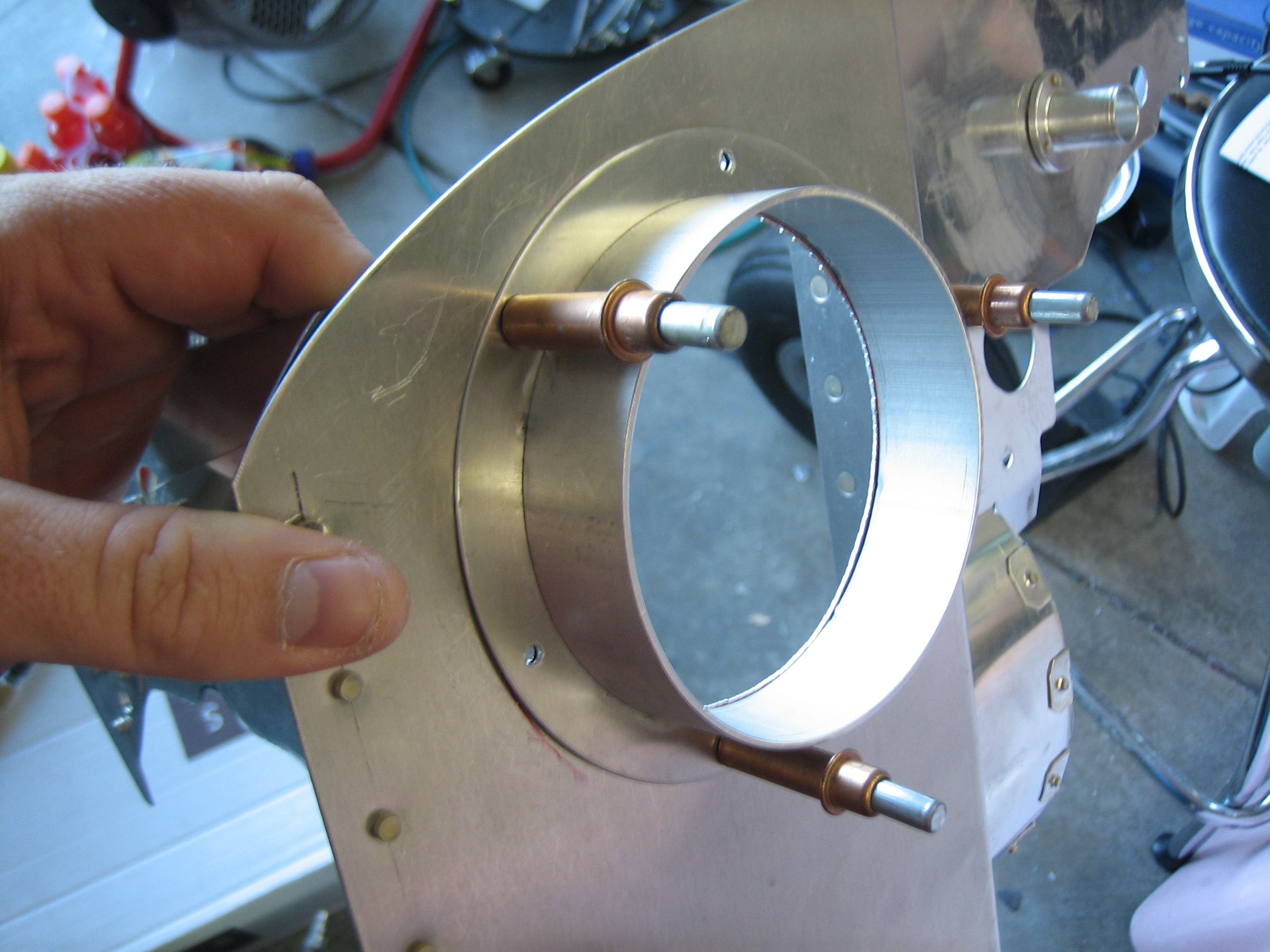
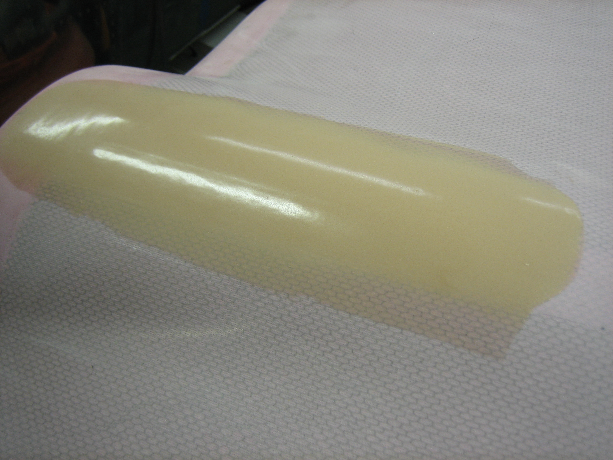
The oil cooler duct flange from Van’s is made of some very thin aluminum and is not welded all the way around. Aircraft Spruce has some spun flanges that I really would have rather used, but they don’t go up to 4″. People have had issues with the Van’s flanges breaking off, so I decided to reinforce this a bit. I mixed up some epoxy/flox and formed a fillet at the joint, then after it cured, mixed up some epoxy/micro to smooth it out a bit. Hopefully this will prevent this from ever separating.
I spread the extra epoxy/micro mixture over the fiberglass tape on the top cowl (covering the holes I drilled when fitting the cowl.
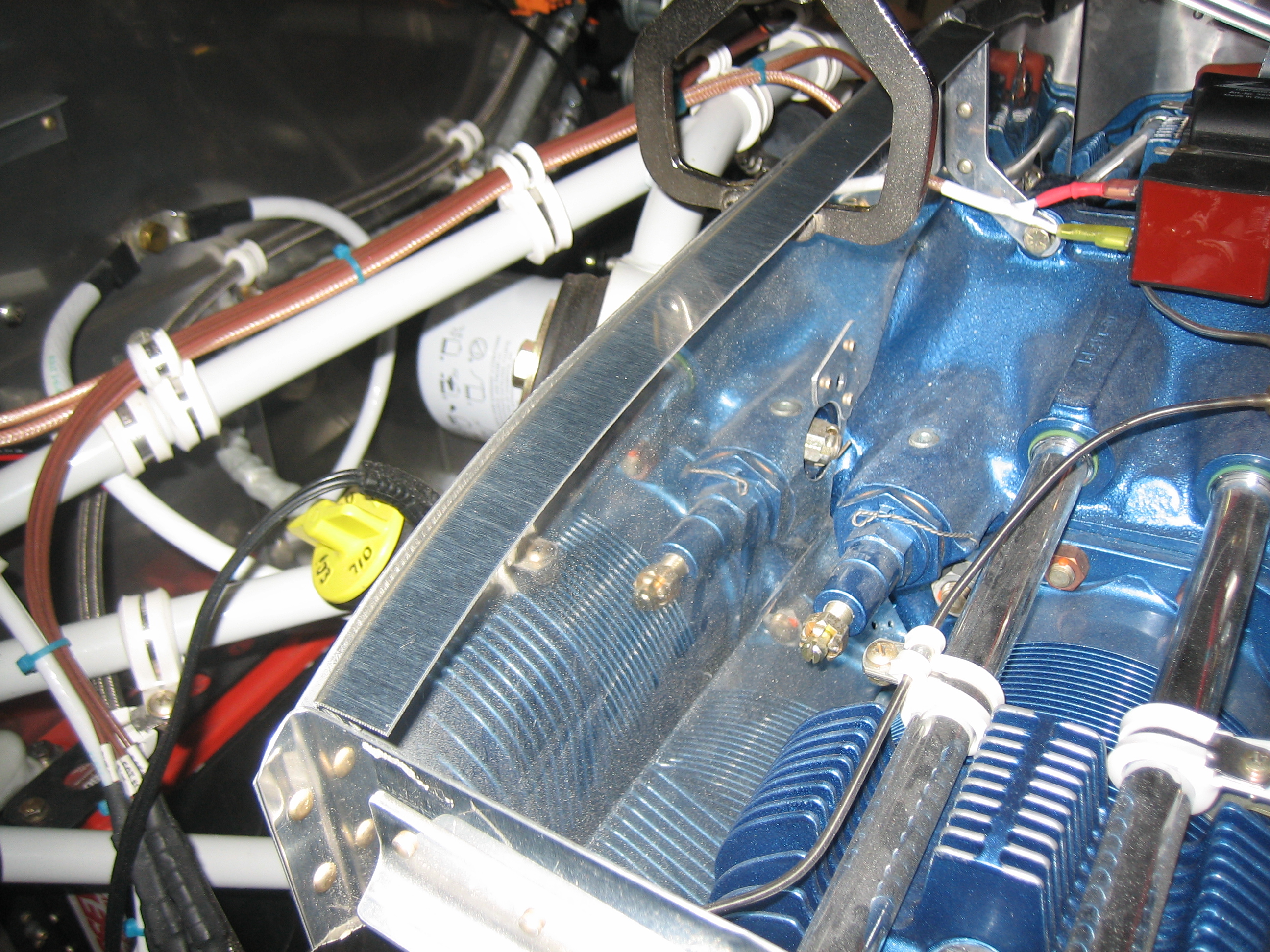
With the epoxy cured on the oil cooler SCAT tube flange, I reinstalled the baffles to test fit the SCAT tube.
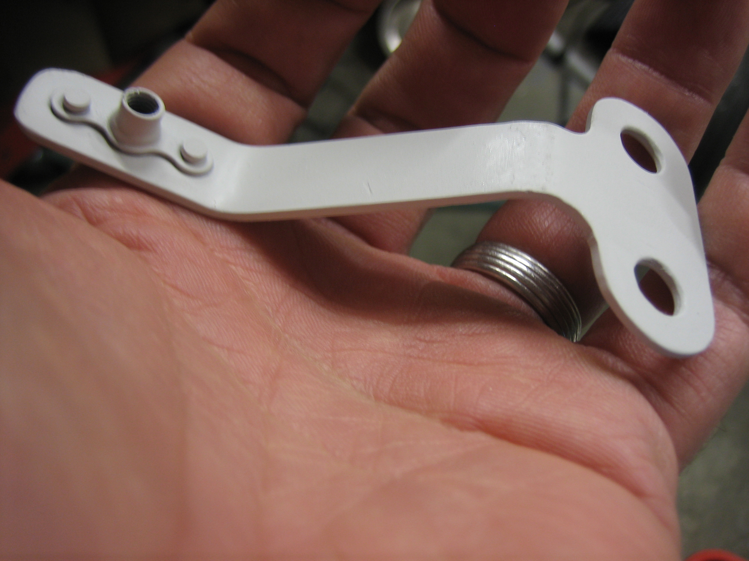
I finished up the alternator cooling blast tube bracket and installed the nutplate. I then painted it with the light gray paint that matches the engine mount powder coat. After the paint cures, I’ll install this tomorrow after the paint has had time to cure.
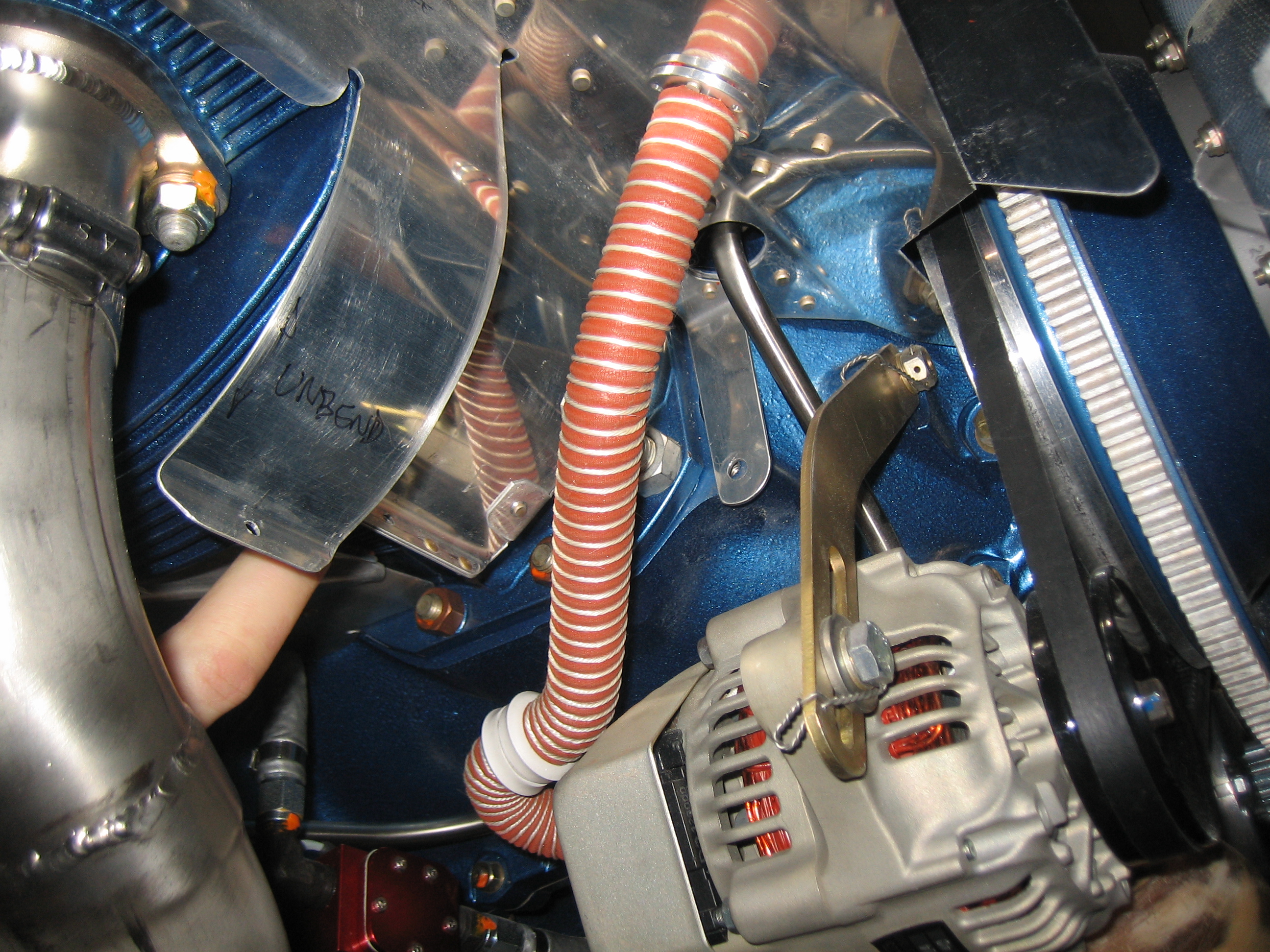
I fit the alternator cooling blast tube. It runs down between the #1 cylinder and the alternator and then turns forward to point at the back of the alternator.
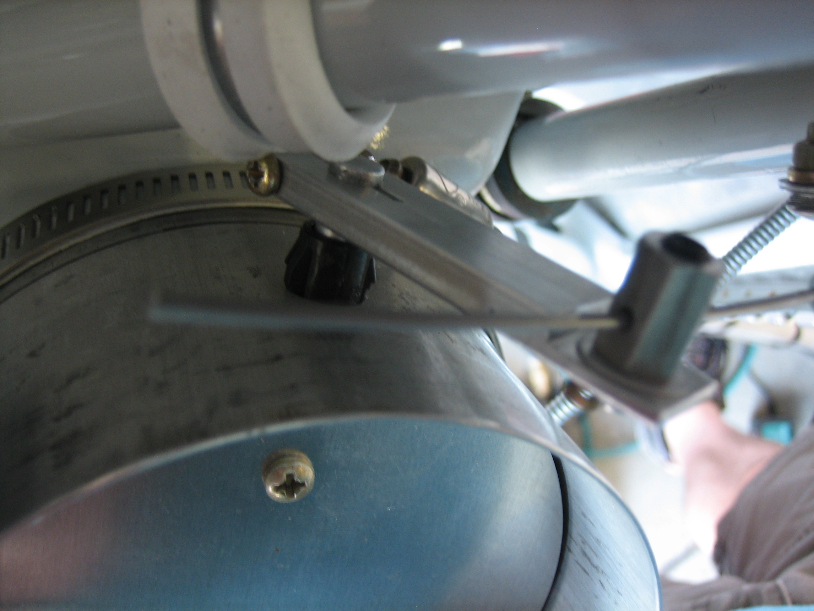
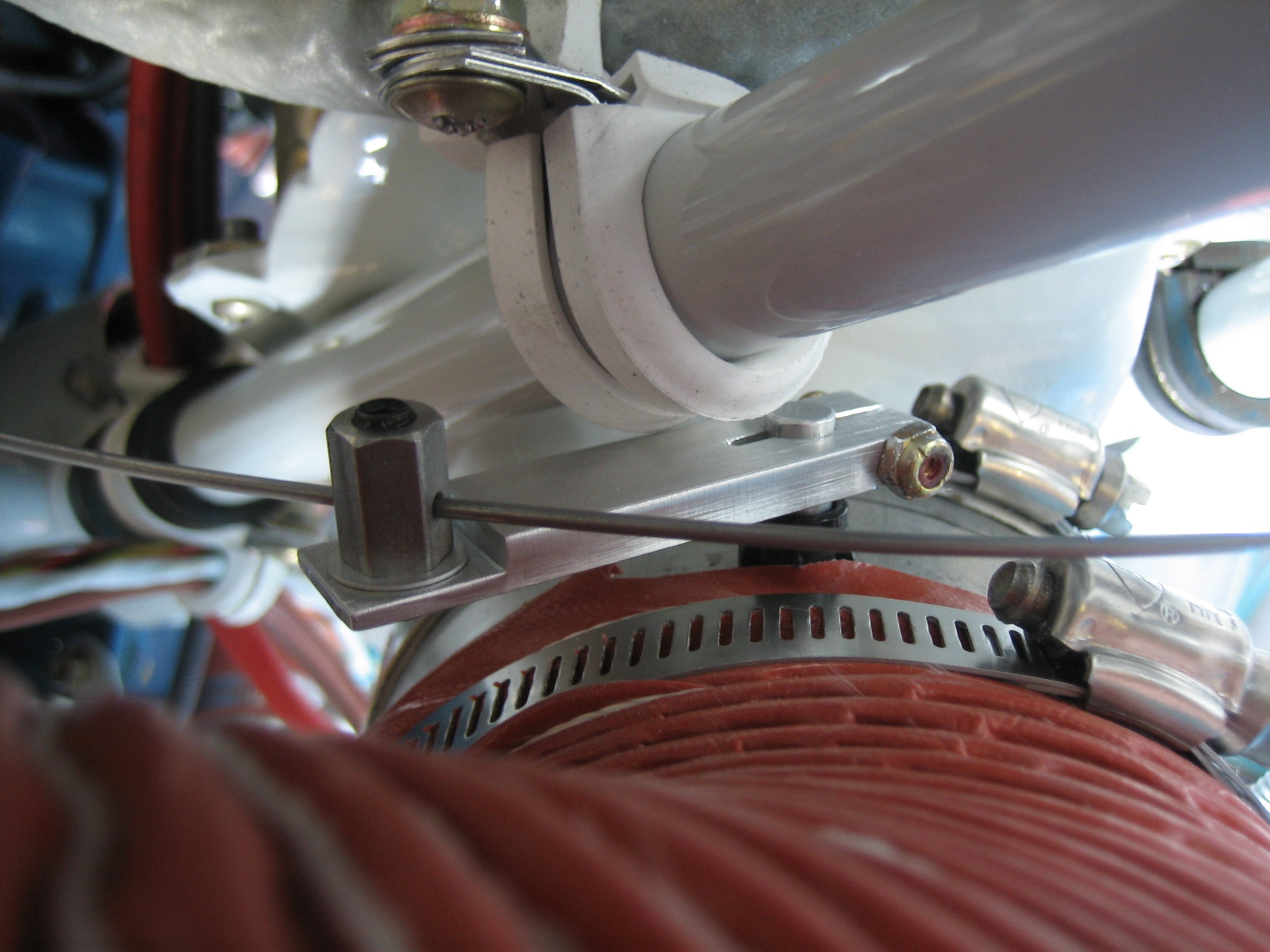
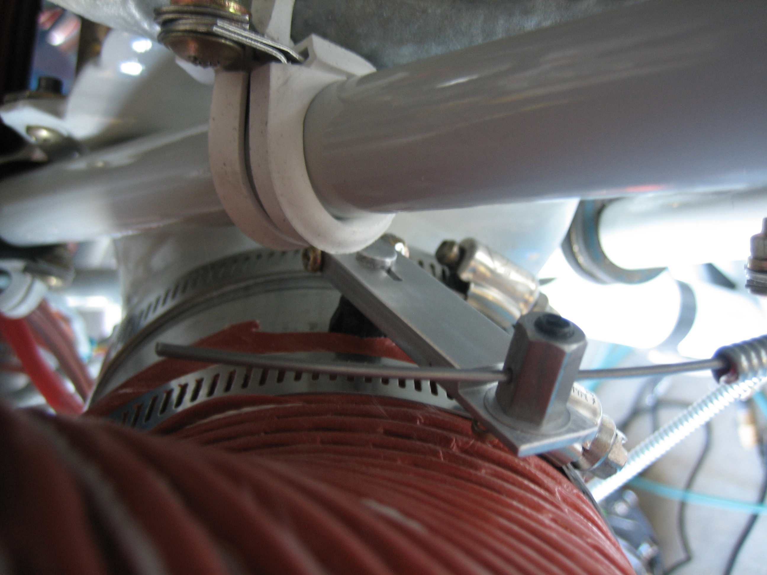
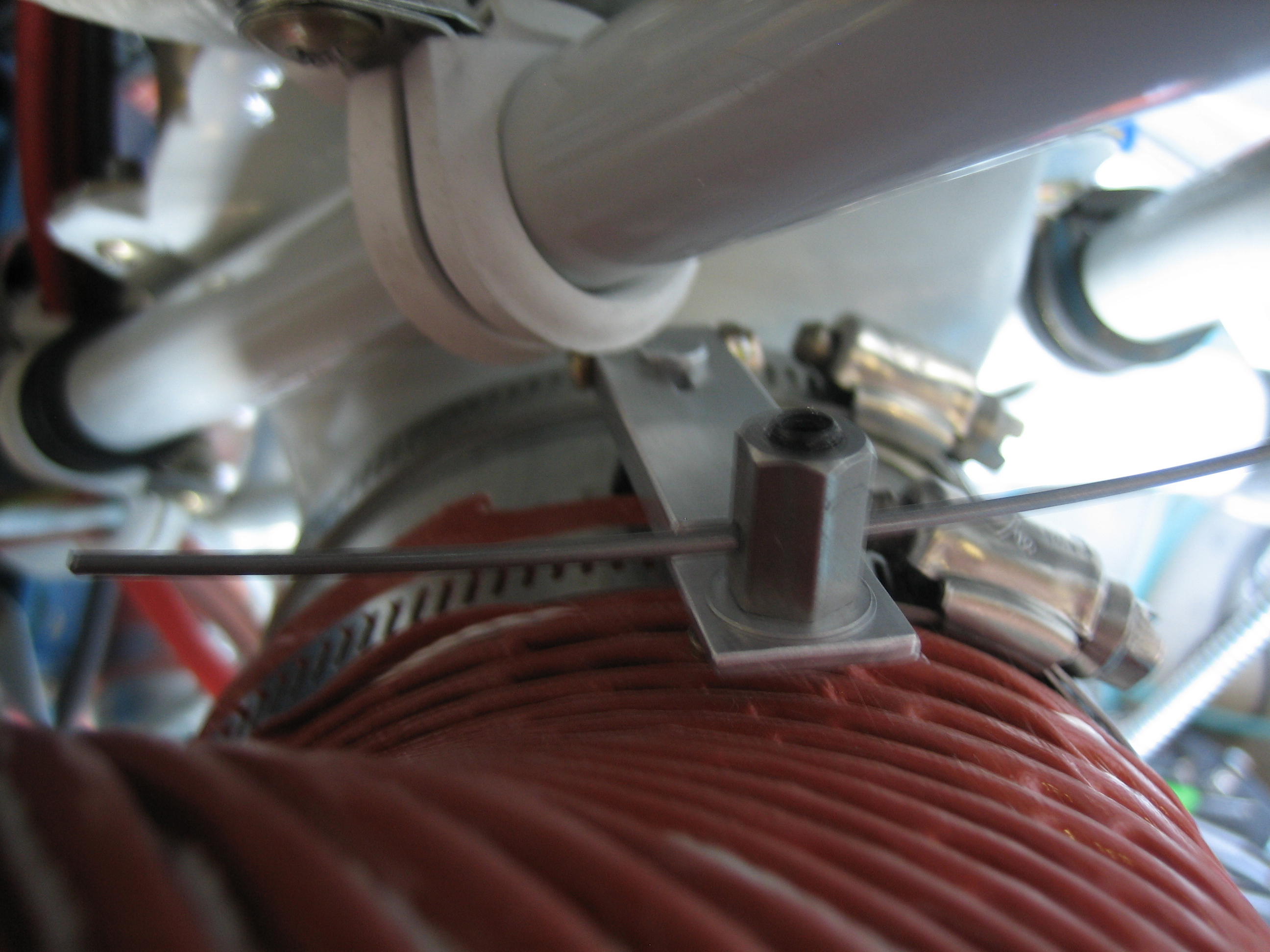
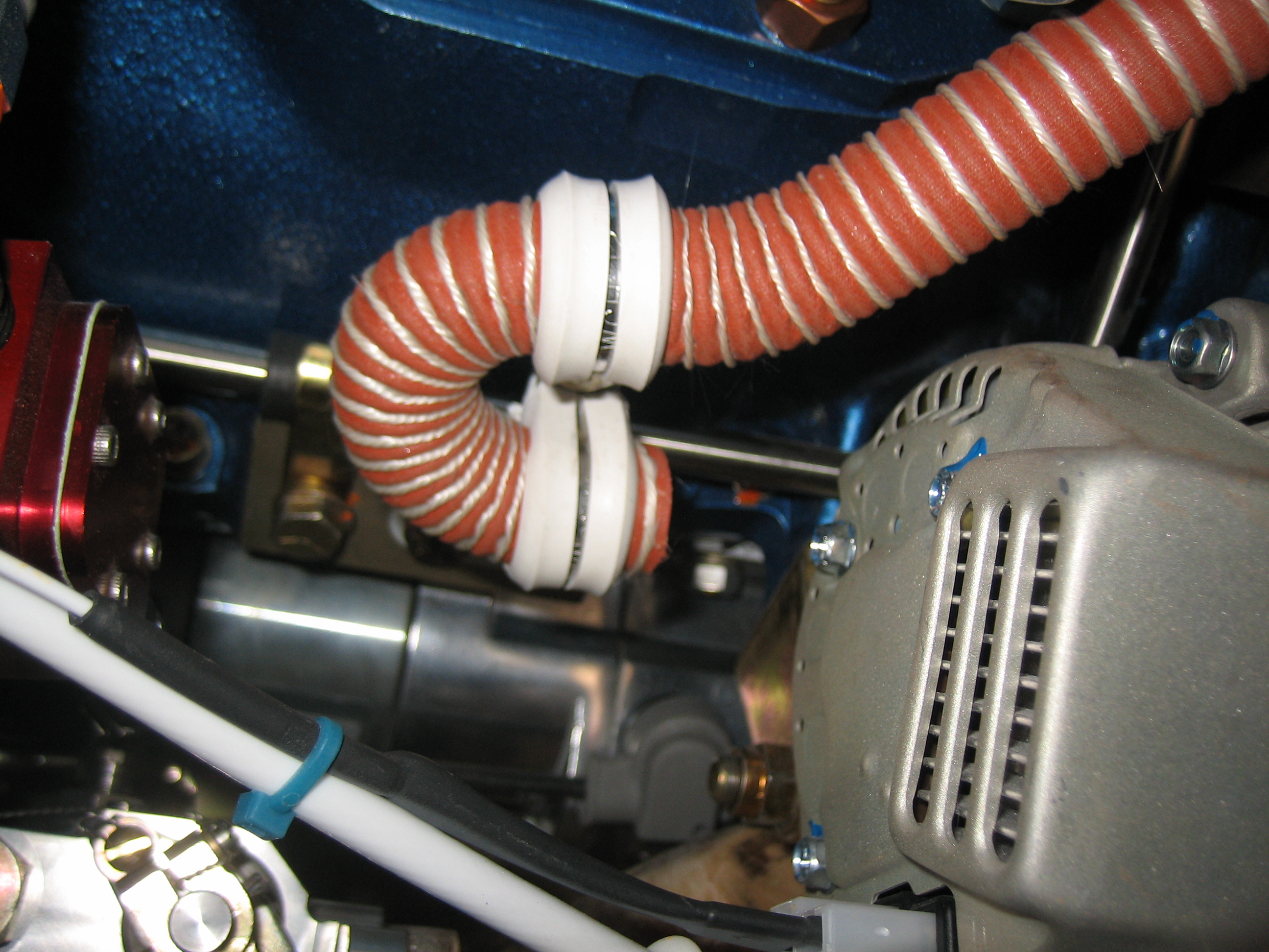
I used a pair of adel clamps to force the SCAT tubing to make a 180º turn. It’s pointed at the center of the arc of slots on the back.
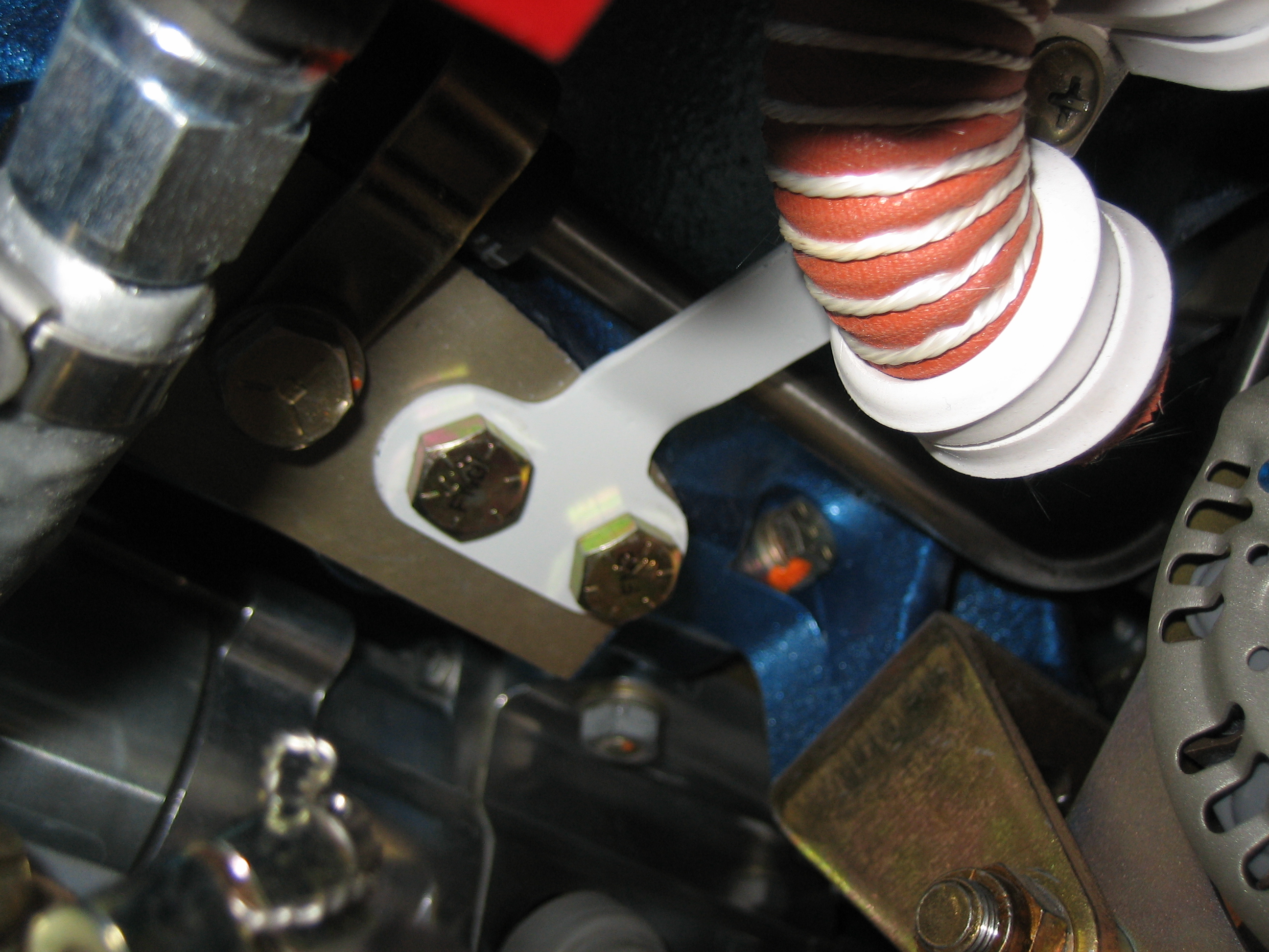
The bracket that holds these adel clamps is attached to the engine just behind the alternator bracket. This is just temporarily attached for now until the baffles are on for good.
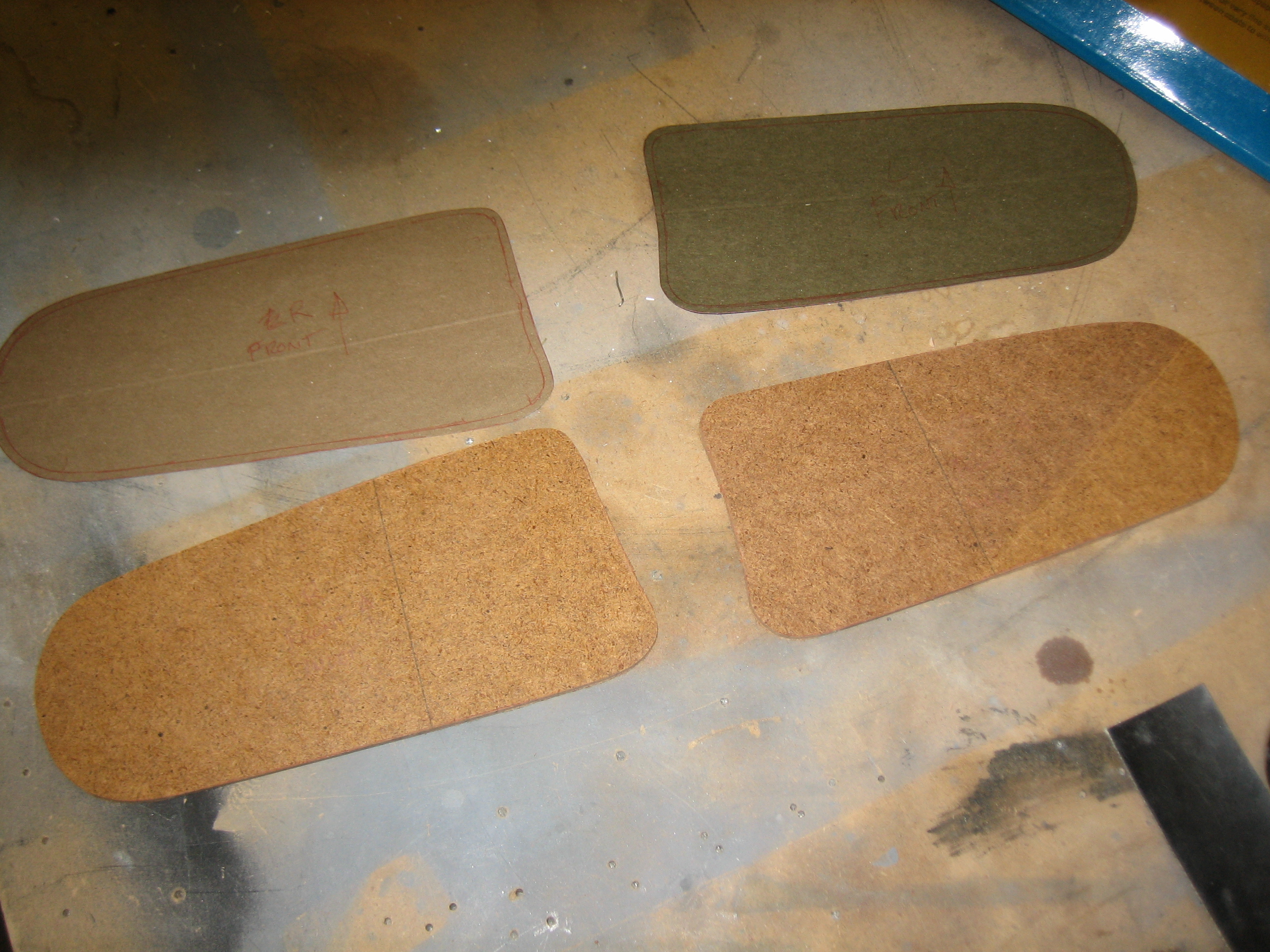
I traced the cowl inlets on some card stock and transferred it to some hardboard. I’ll use these to define the position of the plenum.
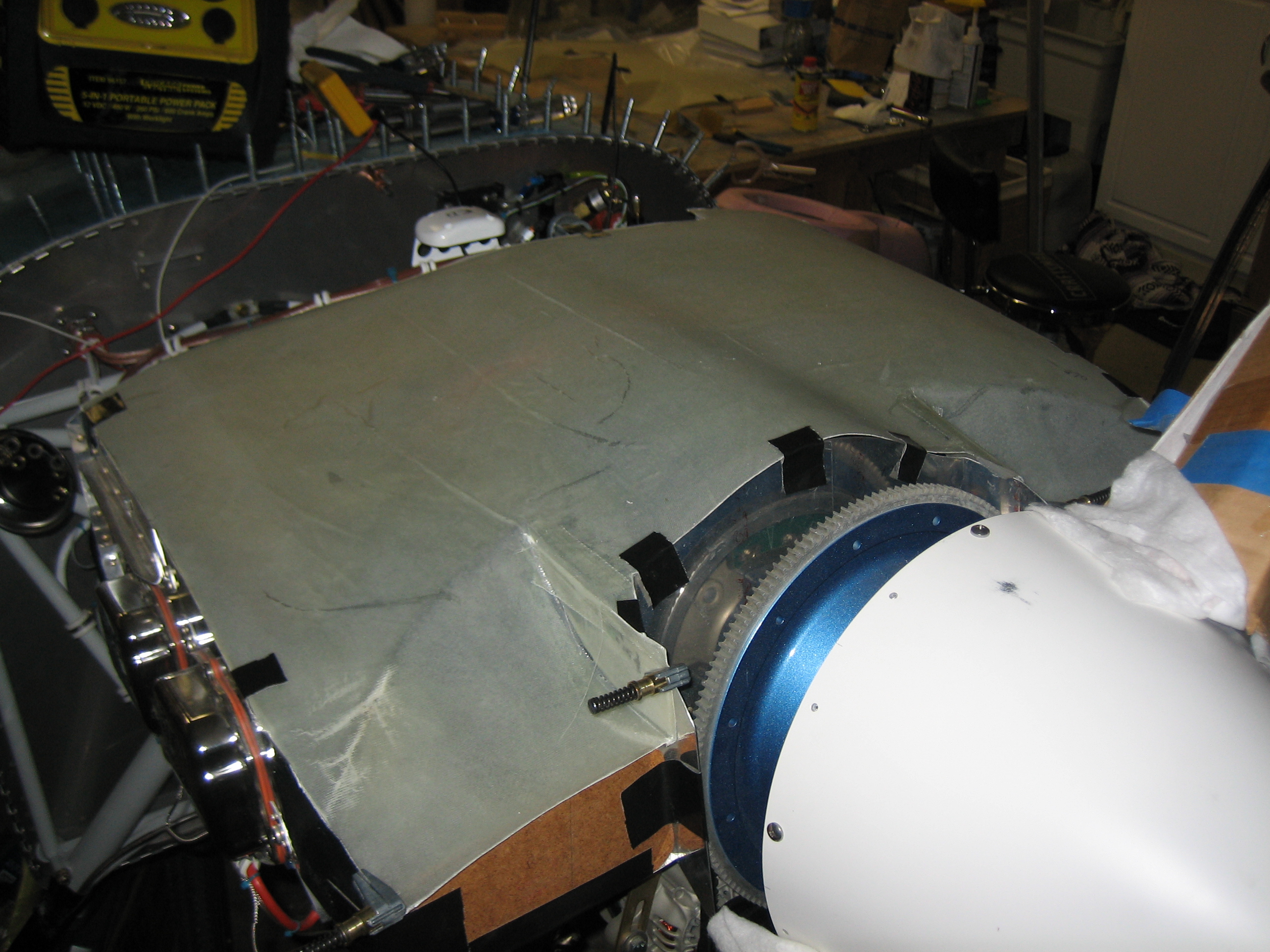
With the templates I made yesterday taped in place, I installed the plenum and taped it down.
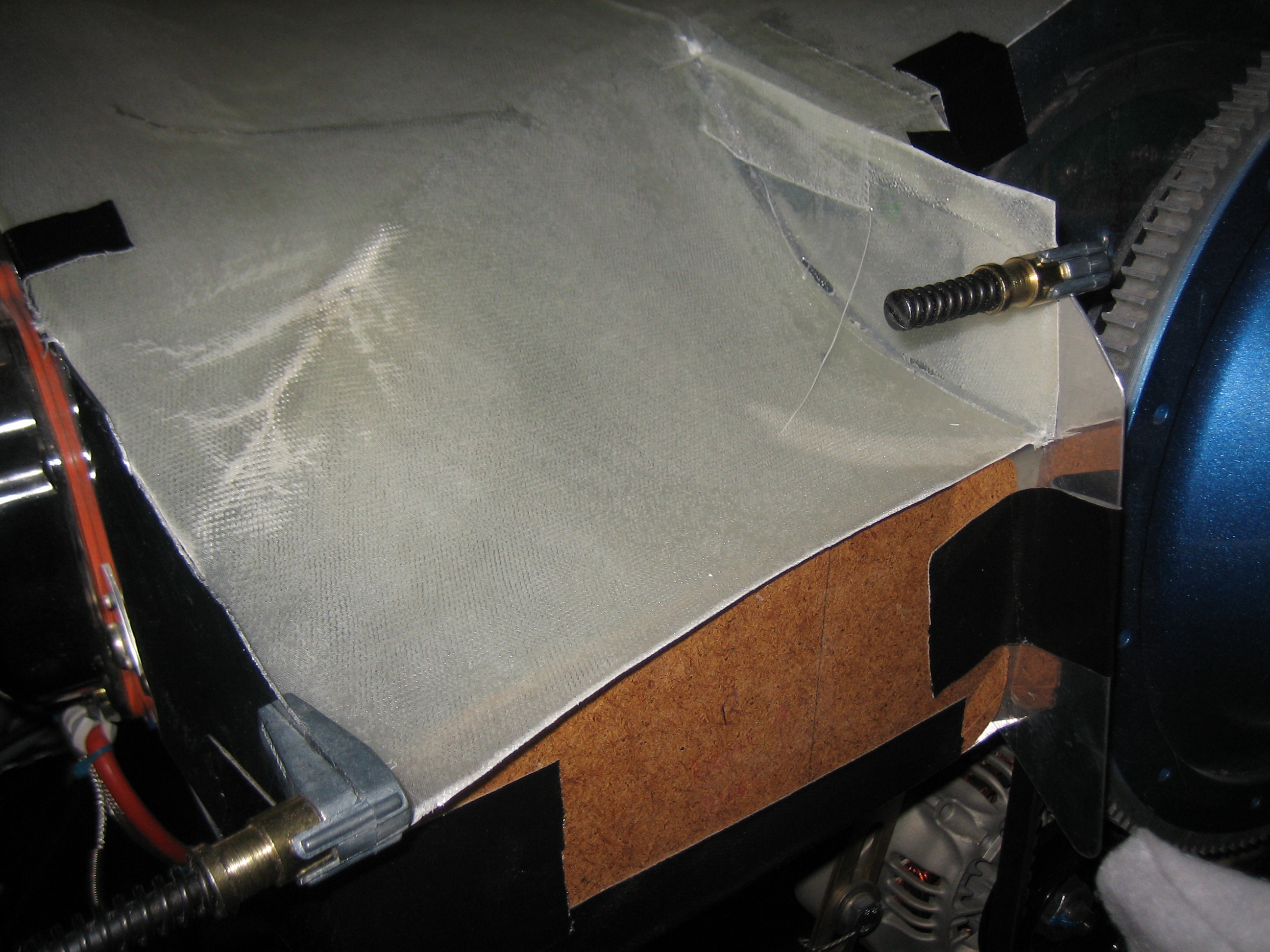
I trimmed the inner edges of the ramps and added some glass to get the plenum to fit tight against the forward baffles. Here’s the right inlet.
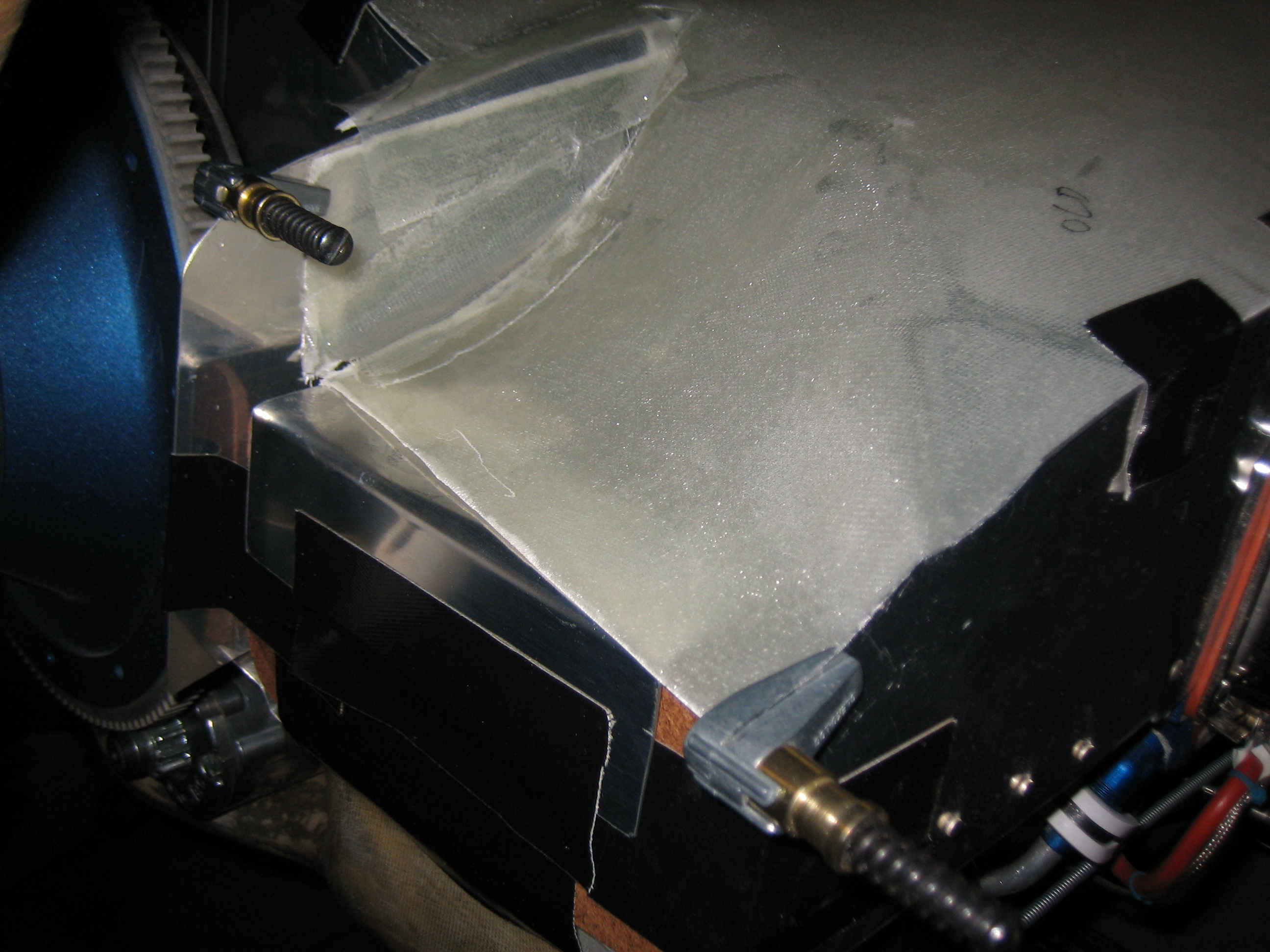
Here’s the left inlet. After curing, these fit really well, but I’ll need to extend the glass on this side about an inch on the inner edge.
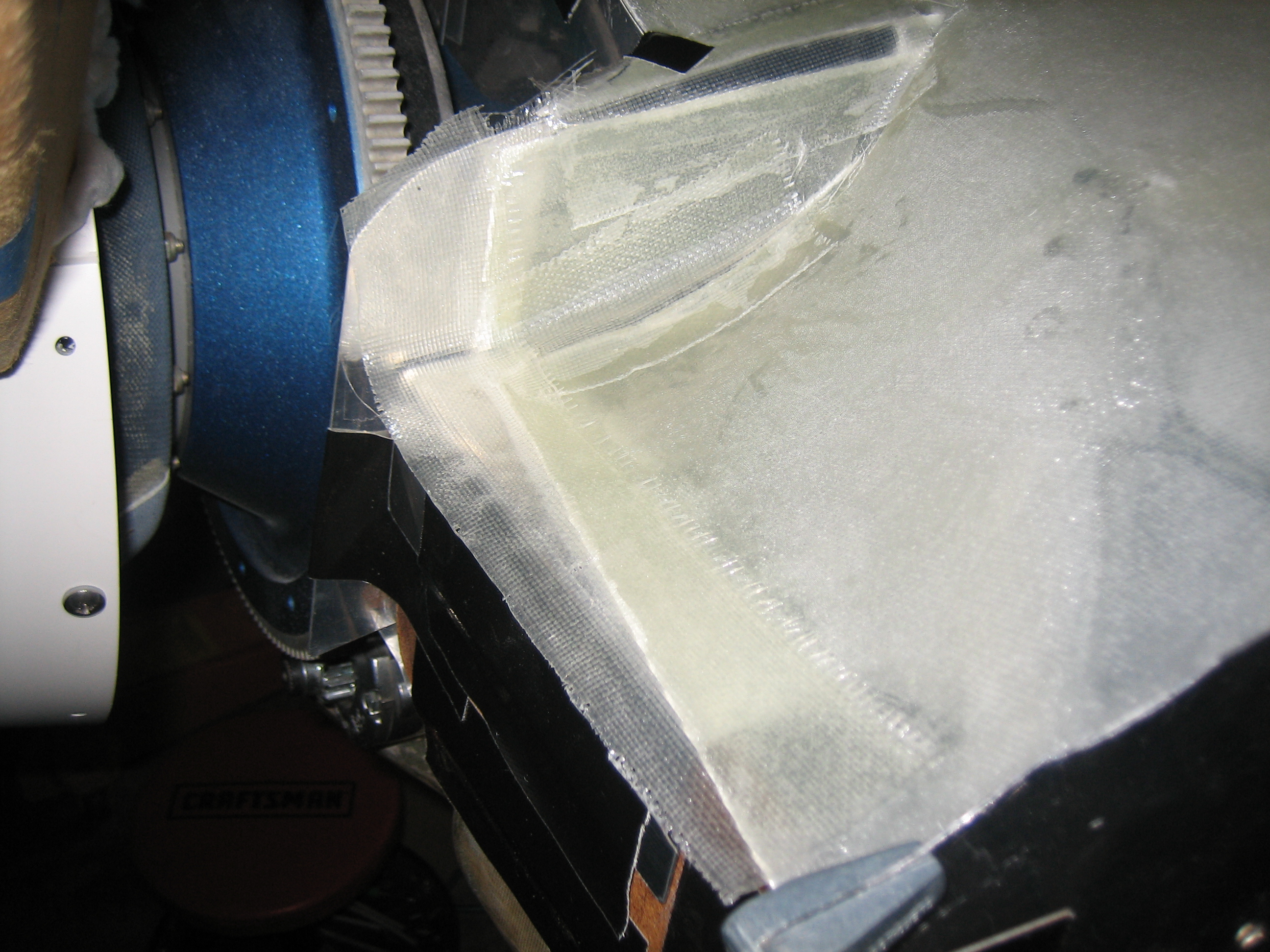
I added more glass to the front edge to bring it out past the face of the template.
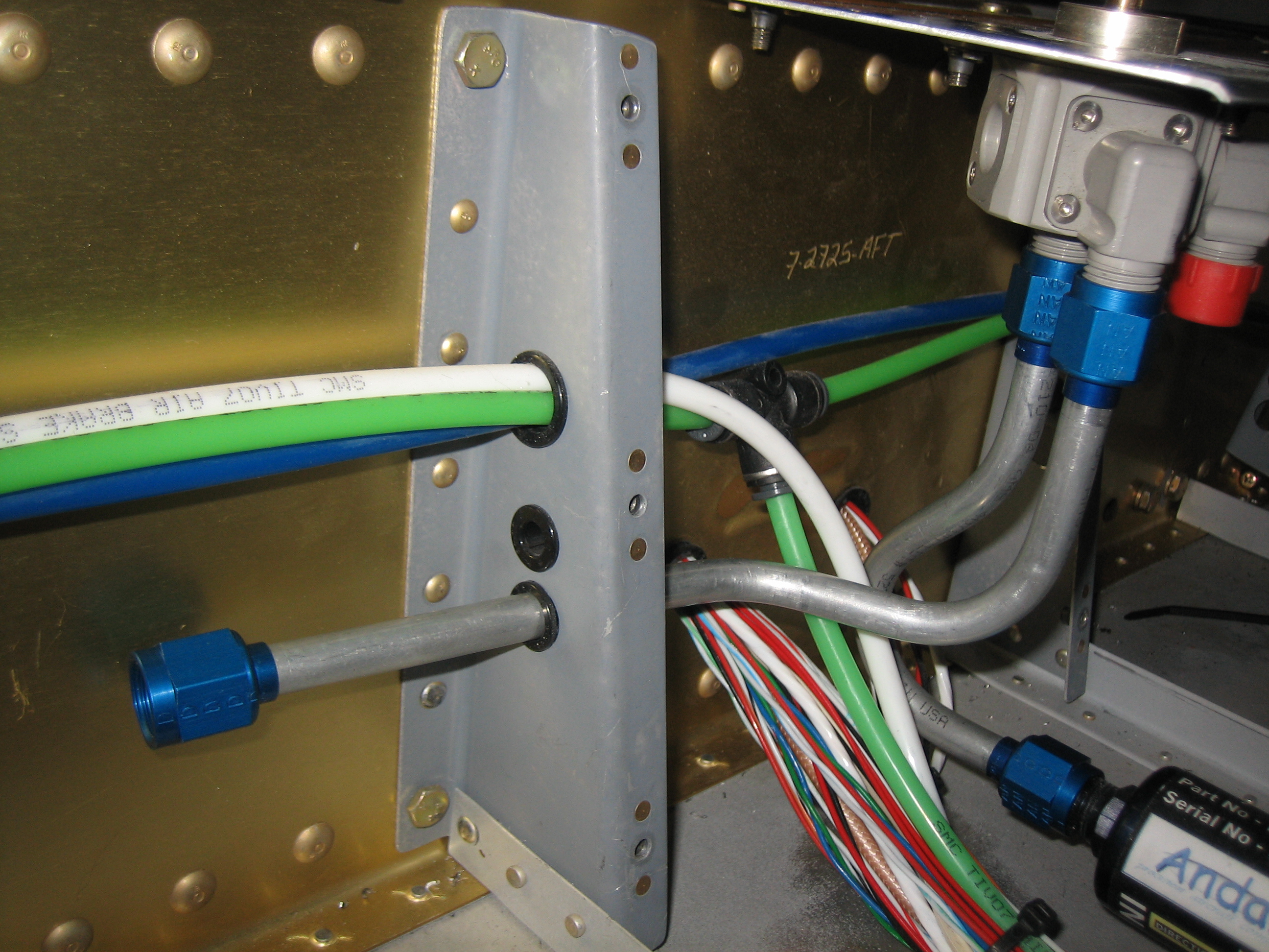
While the fiberglass was curing, I got started bending the fuel lines that go from the fuel selector out to the wings. Each side will be done in three pieces, a piece from the fuel selector to between the support brackets (as seen here), a second piece from between the support brackets to just outside the fuselage, and a third piece from there up to the fuel outlet on the tank. Each section will be joined with an AN815-6D union. This is necessary because it’s essentially impossible to maneuver longer pieces through the holes in the support brackets.
I started fabricating the plenum mounting angles tonight. These are a little tricky because they’re not 90º and they’re all curved. Here are a couple of the ones around the oil cooler air inlet.
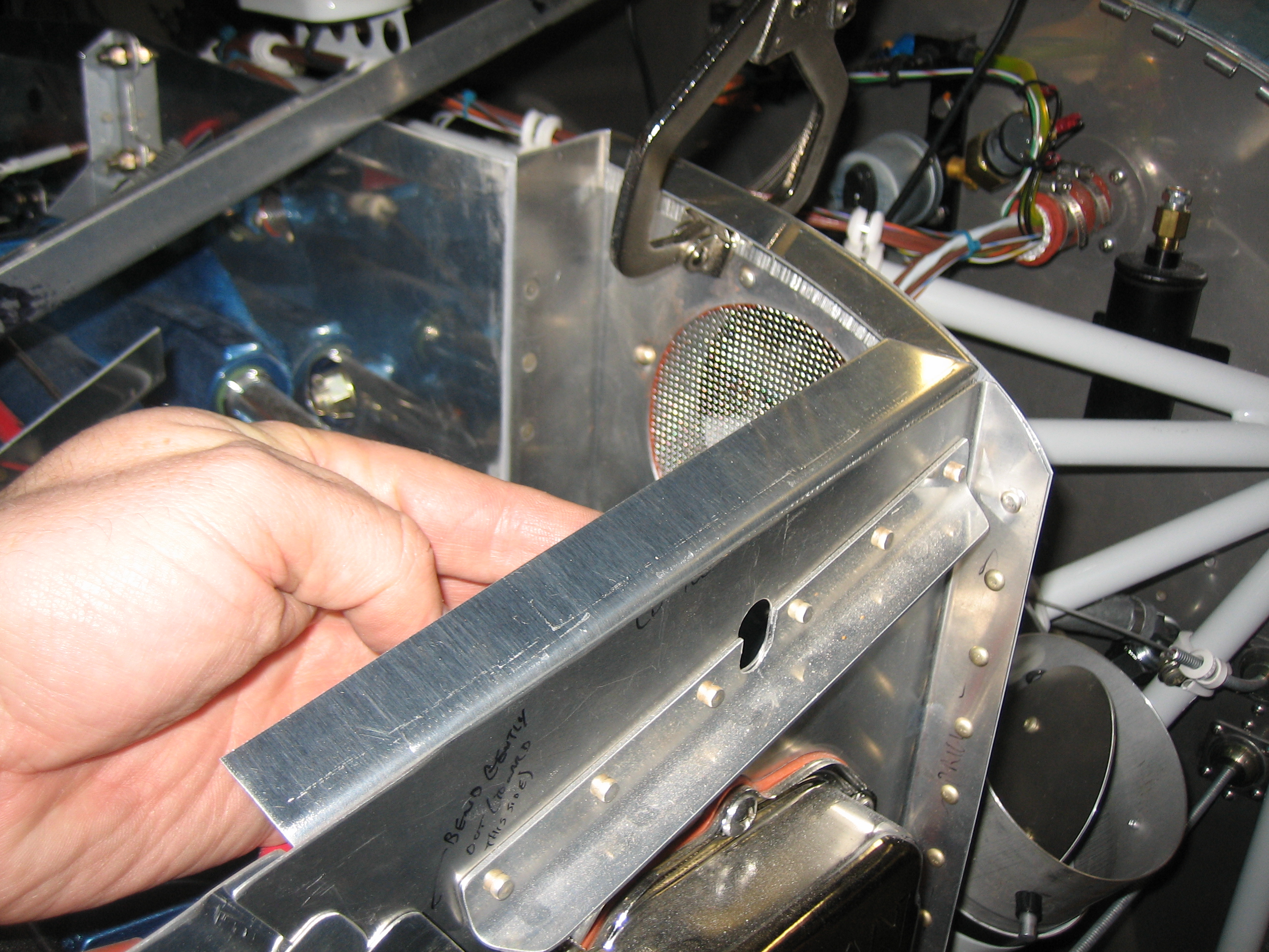
Here’s the angle along the aft edge on the right side. There’s a fairly severe curvature near the end.
I’m using my shrinker/stretcher to curve the angles.
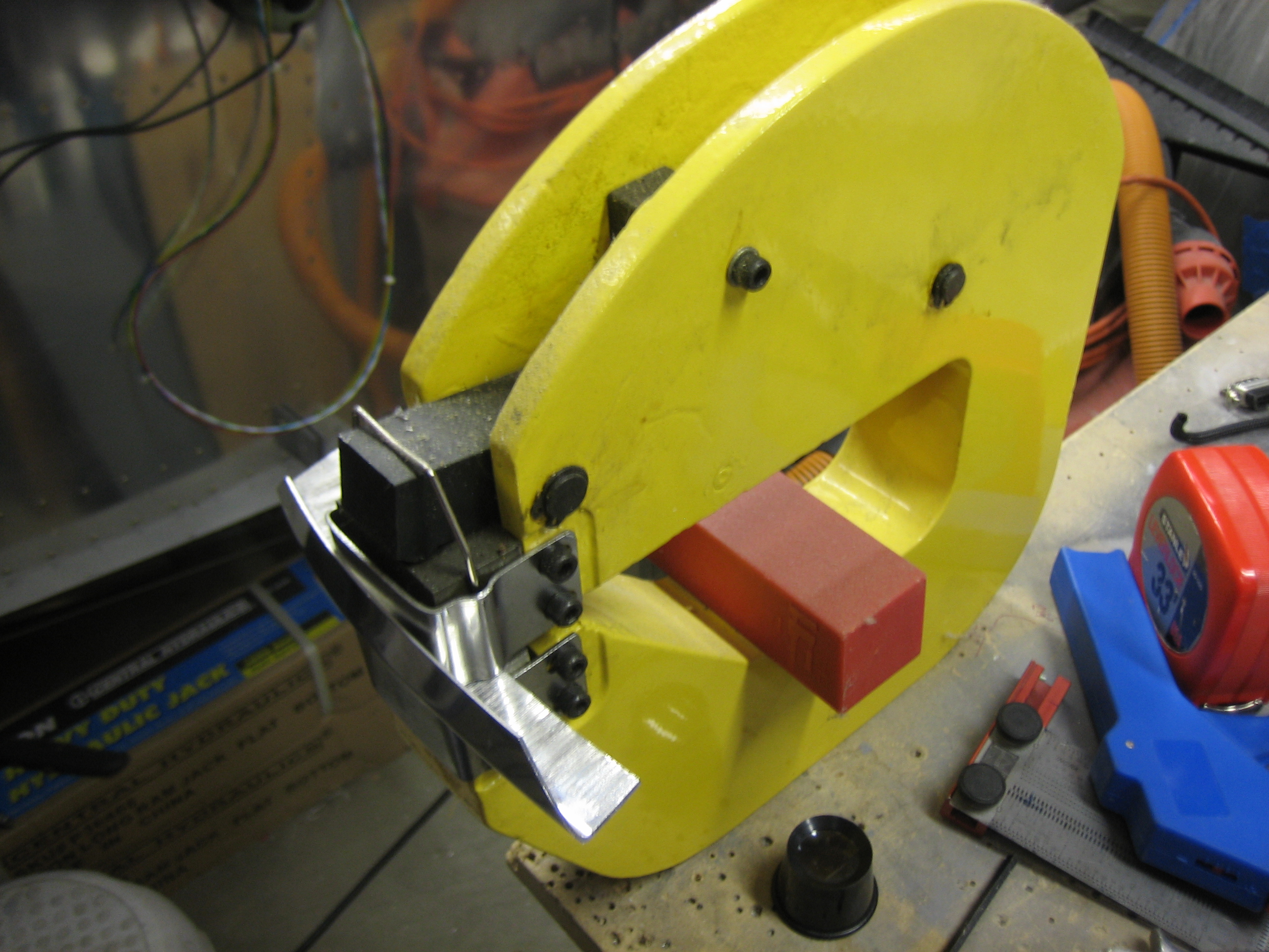
This is angle above the oil cooler air inlet. The shrinker/stretcher leaves some fairly deep marks in the aluminum, but these will sand out.
