Finished Wiring SkyView Network

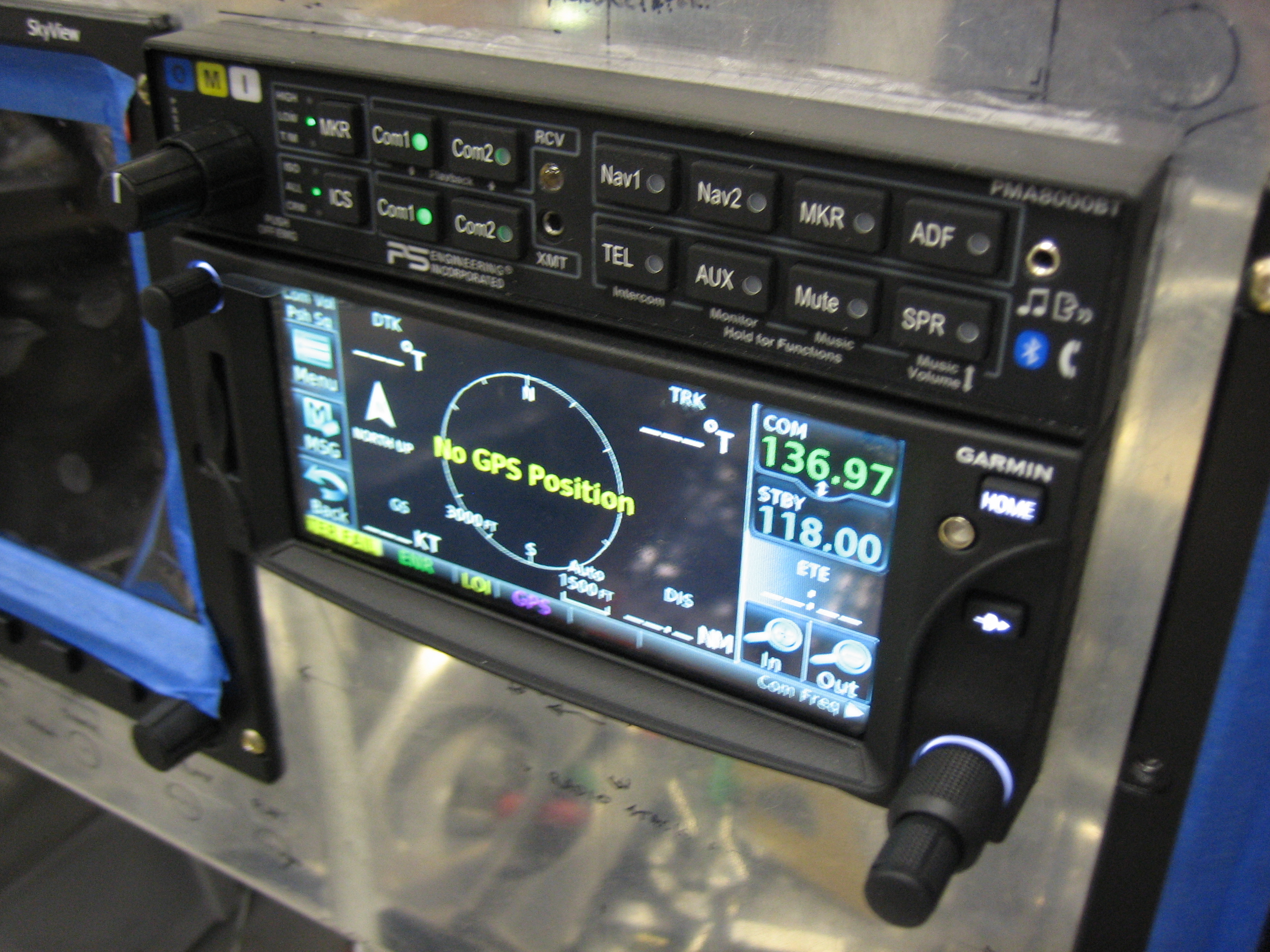
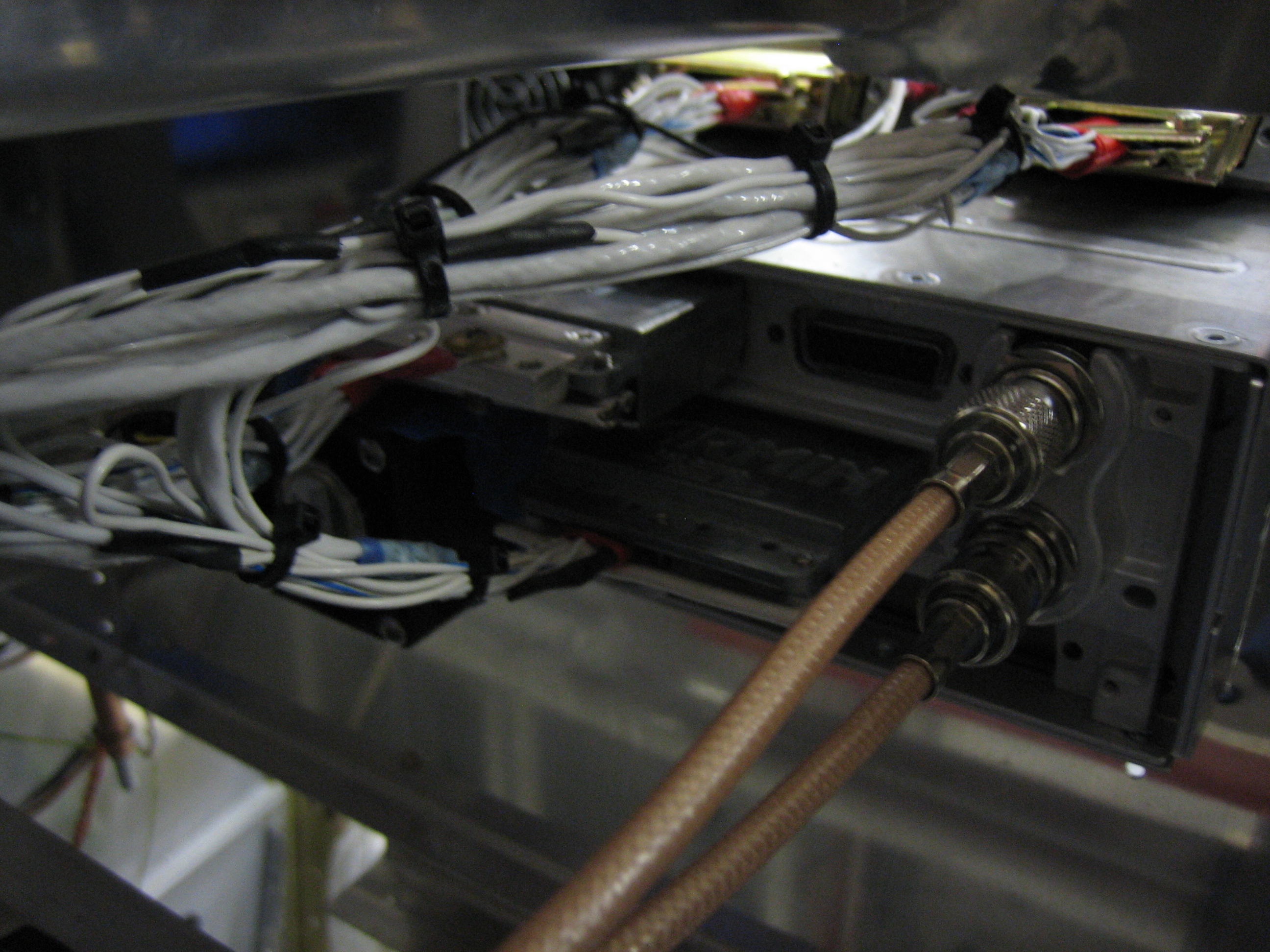
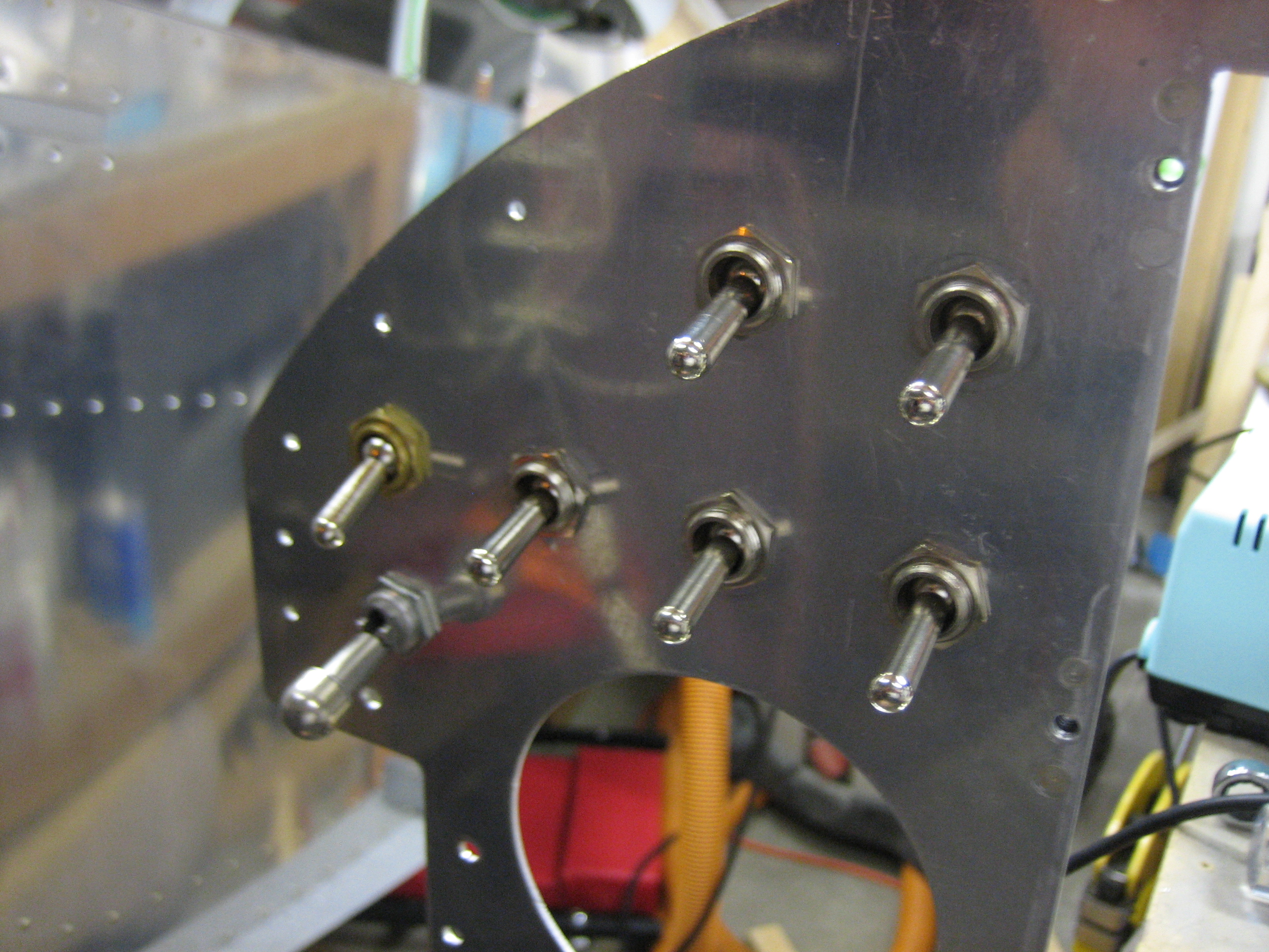
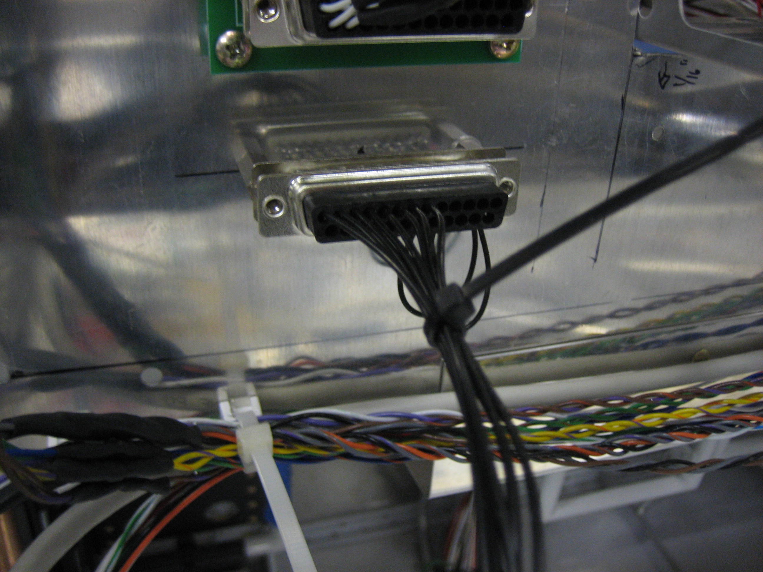
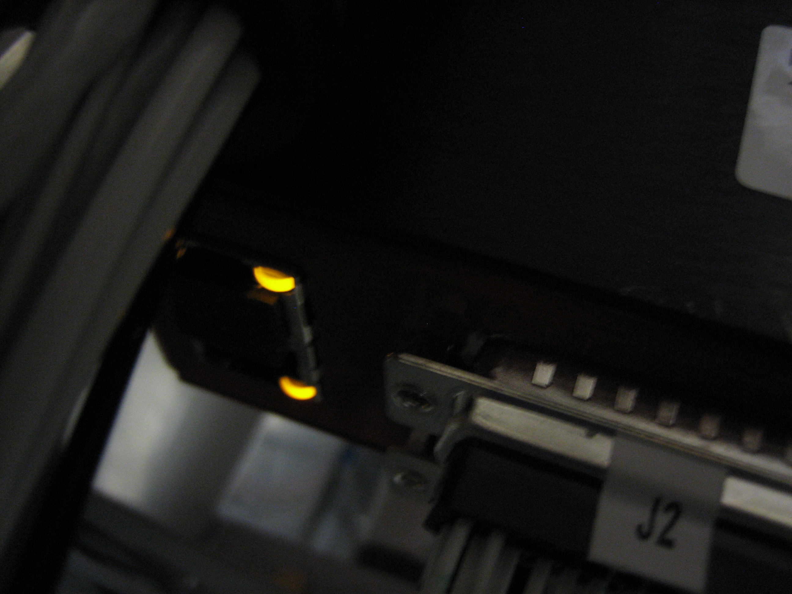
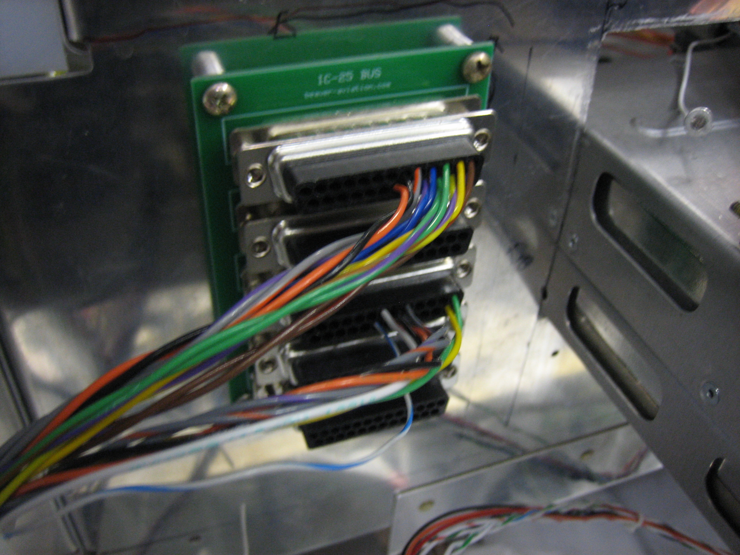
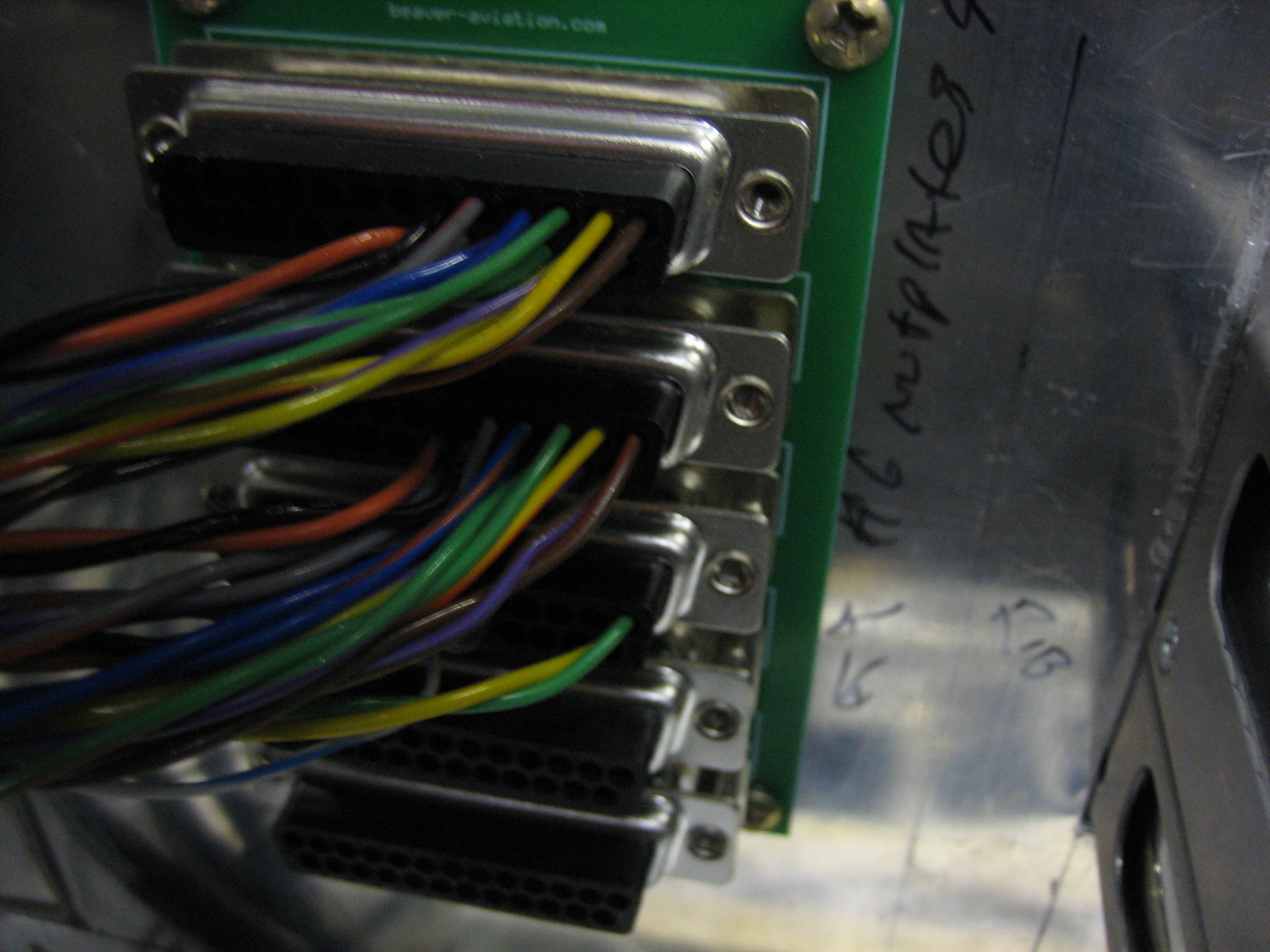
With the screens in place, I started hooking up the serial ports to the interconnect bus I made.  The top connector is for the left SkyView screen.  The next one down is for the right SkyView screen.  The third is for the other accessories in the aircraft (SkyView GPS, transponder and ELT).  The fourth will be for the GTN 635 and the bottom one will be for the audio panel.  I haven’t hooked up the SkyView audio outputs or dimming input/output since the SkyView install manual says not to until they’re supported in software.  When this is eventually supported, all I will have to do is plug the appropriate wires into the appropriate holes to hook them up.

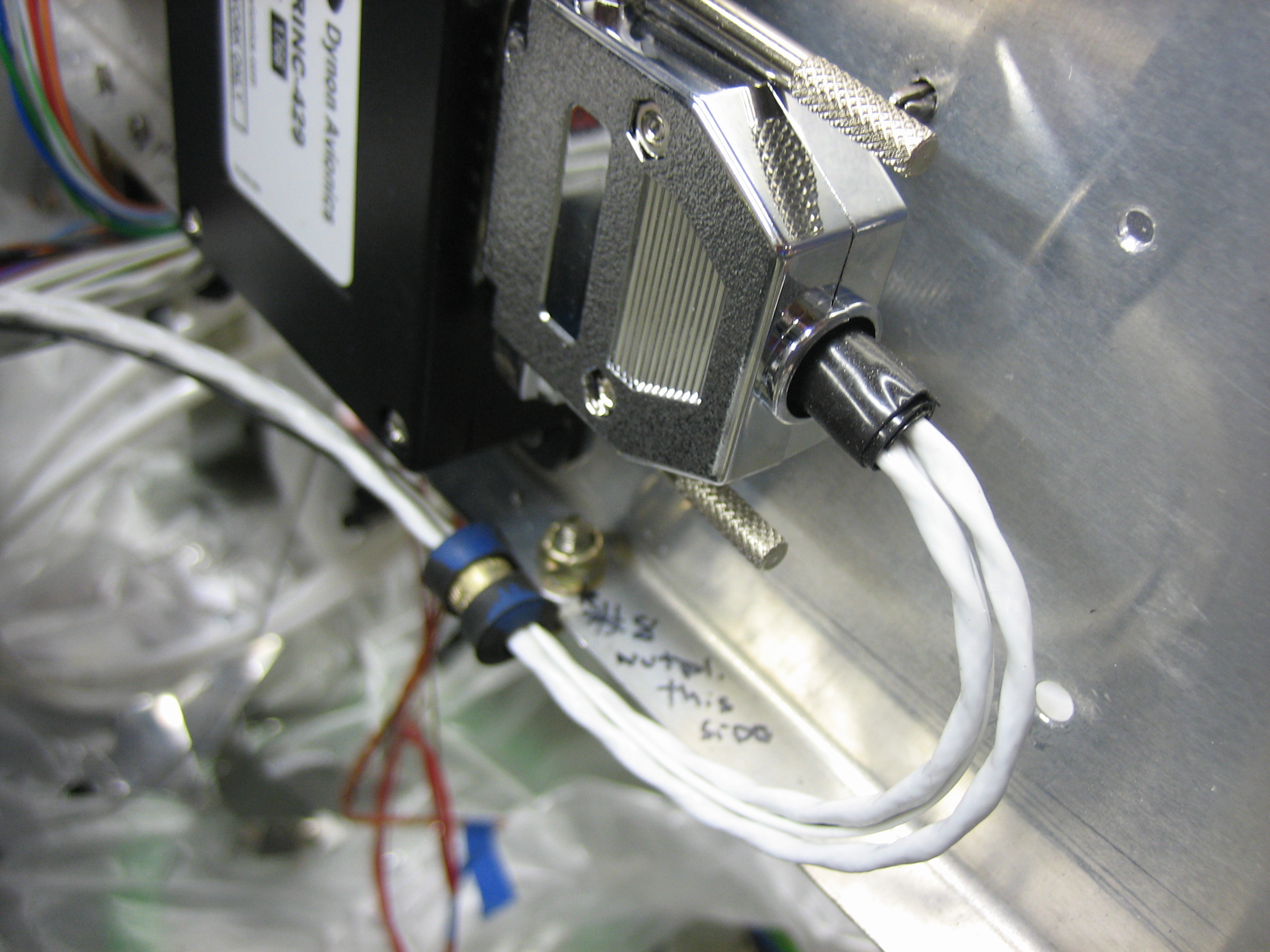
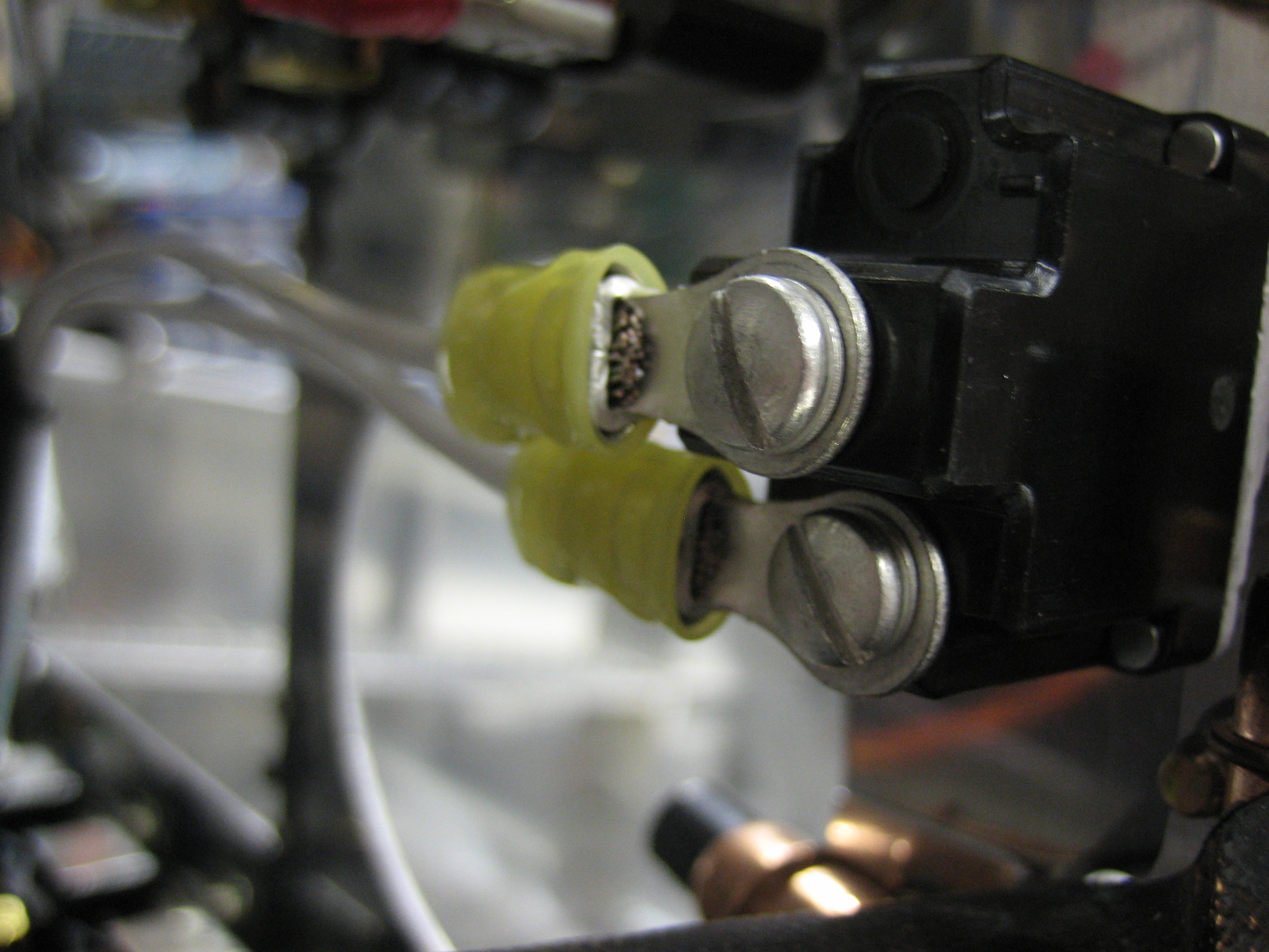
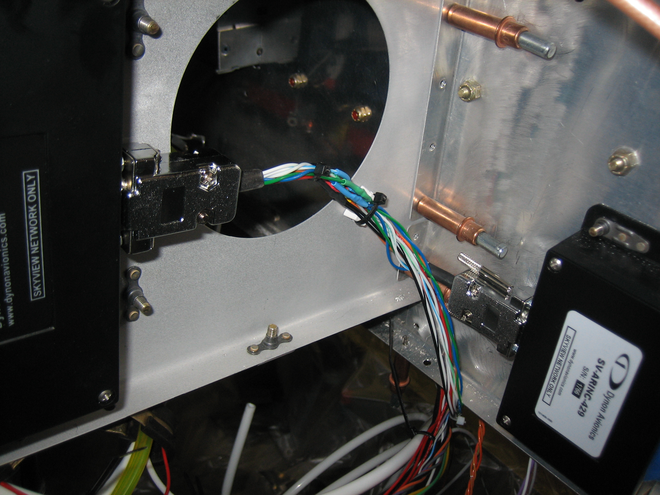
I also finished fabricating the SkyView network cables.  Here is the connection between the EMS and the ARINC-429 box with a tee over to the left SkyView screen.  If you look closely, you’ll notice that the connector on the ARINC box (on the right) has thumb screws, while the one on the EMS has small screws that need a screwdriver.  I’ve swapped most of the thumb screws for small screws, but left a few where access is restricted.

I bypassed the VP-X temporarily and fired up the SkyView screens.  Initially, the left screen was running 2.6 (I think) and the right screen was running 3.1.1, so not everything was working properly.

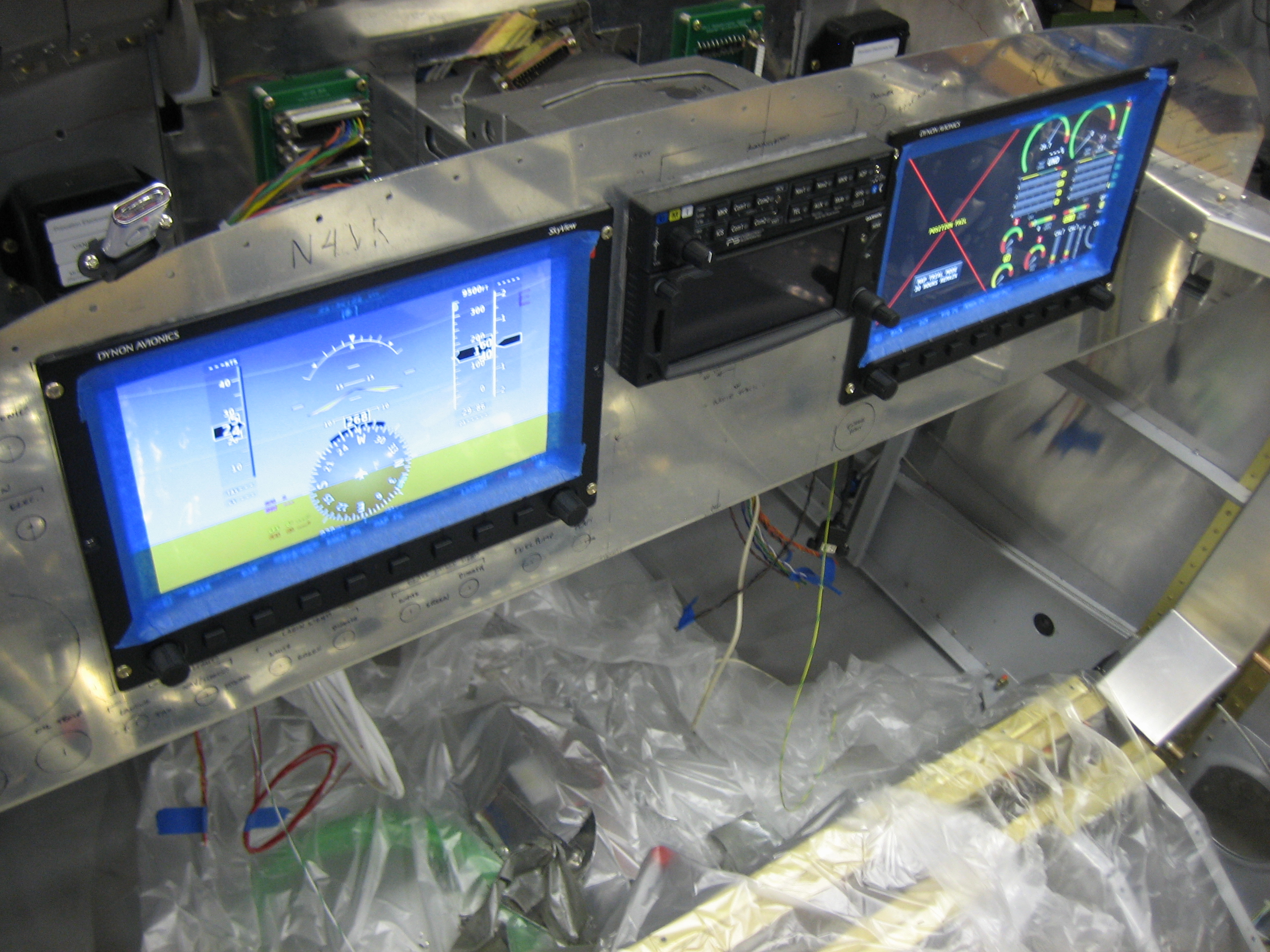
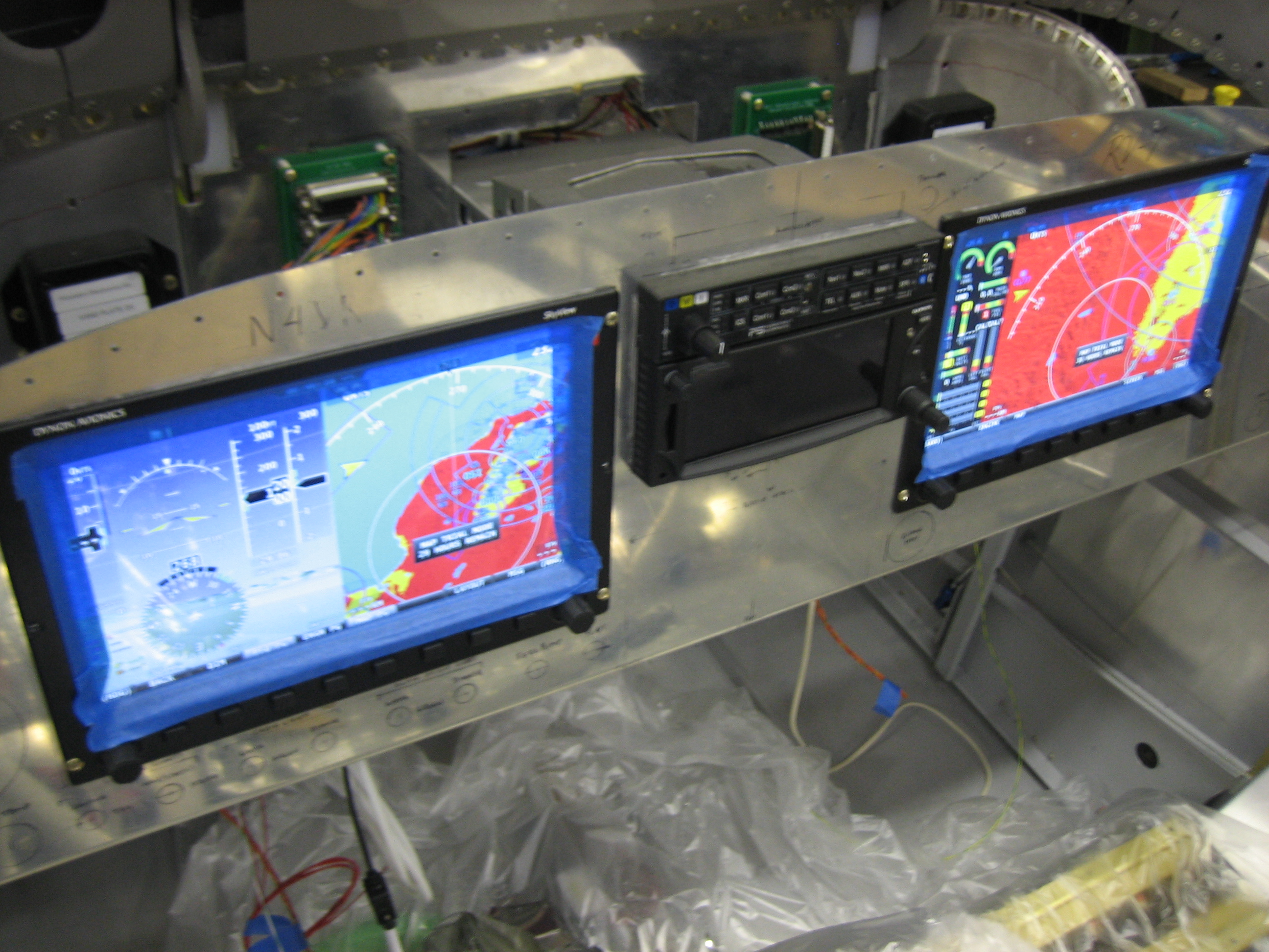
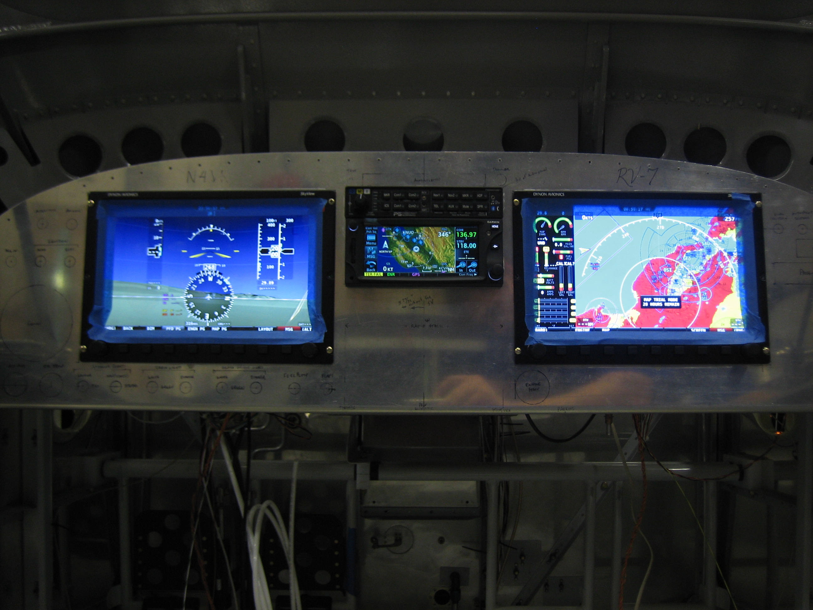
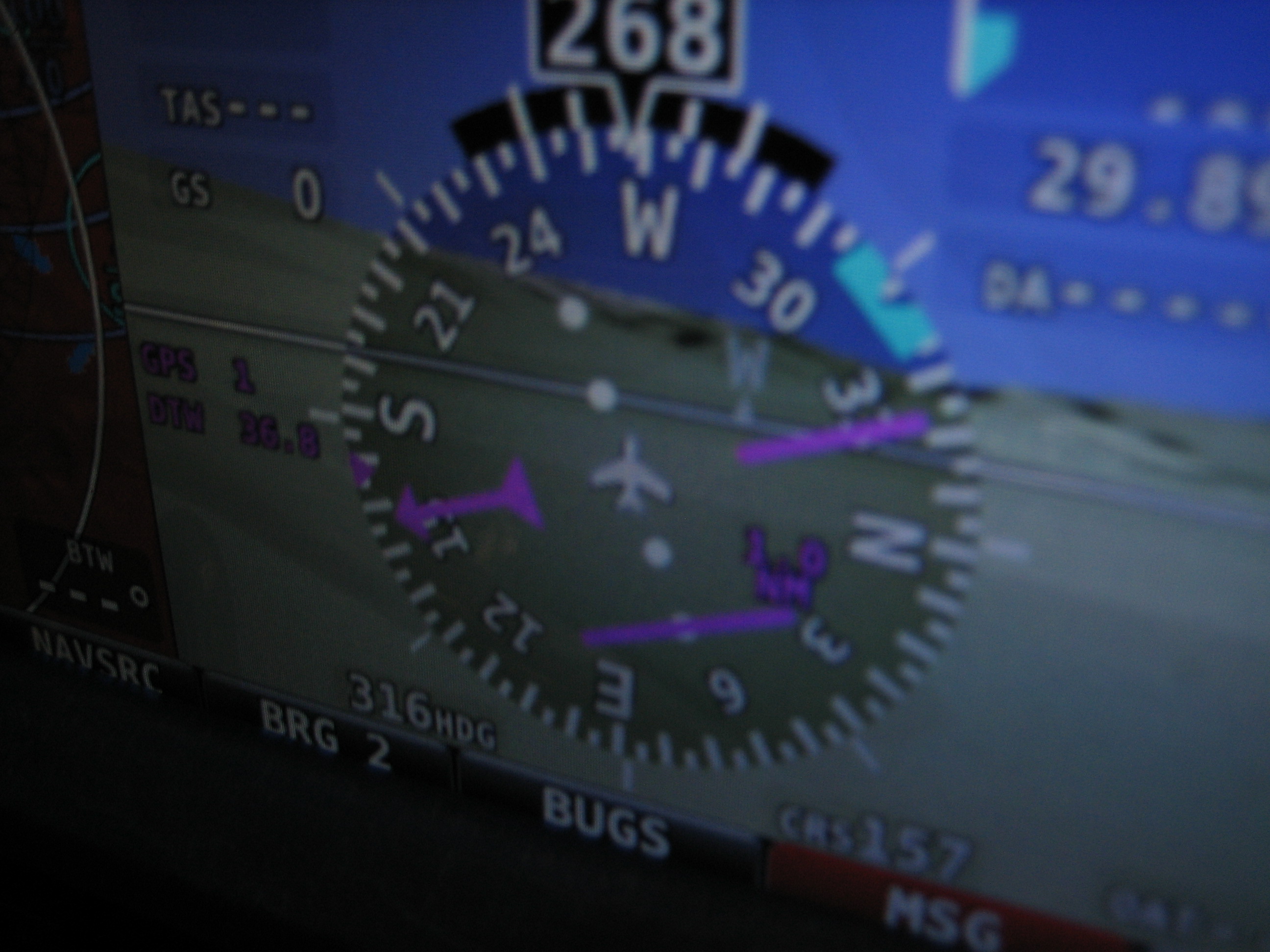
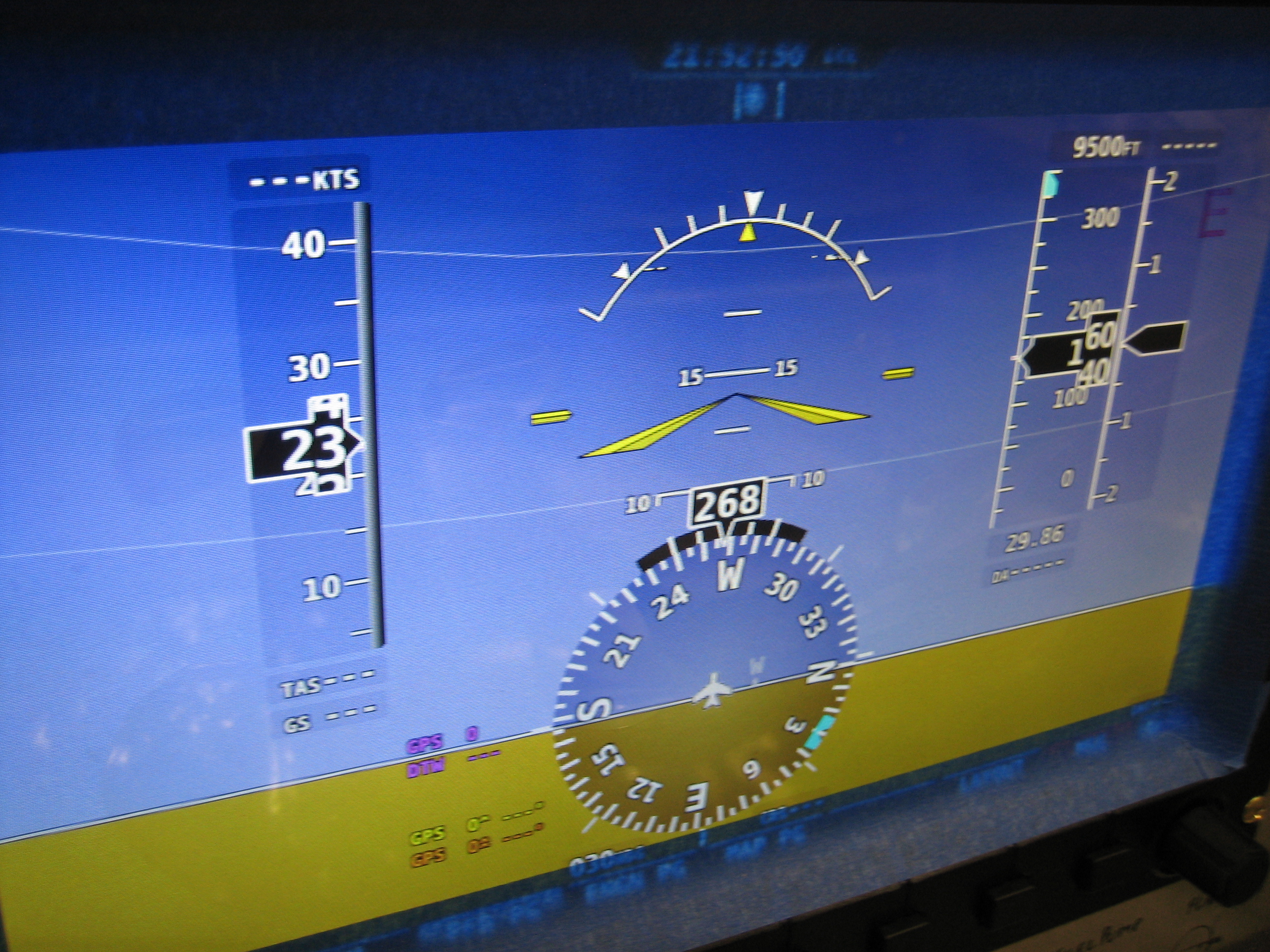
The left screen was showing proper attitude, but no synthetic vision.

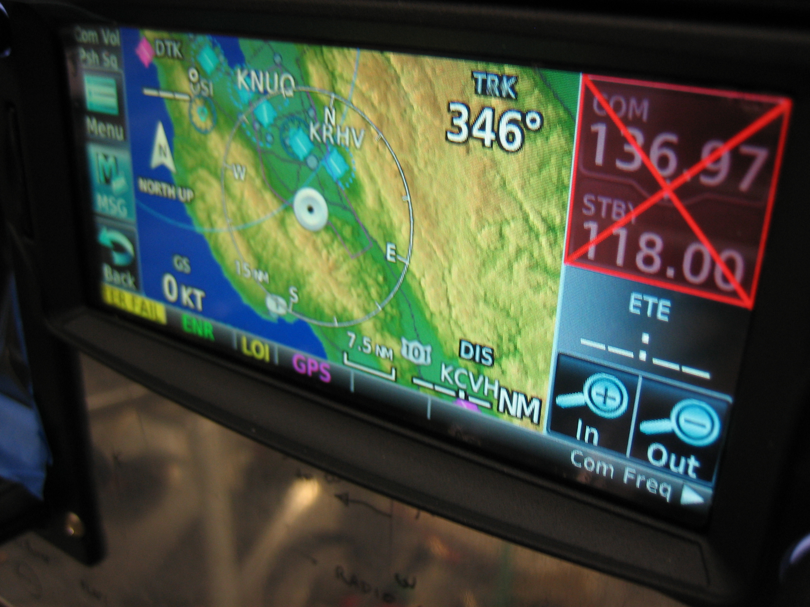
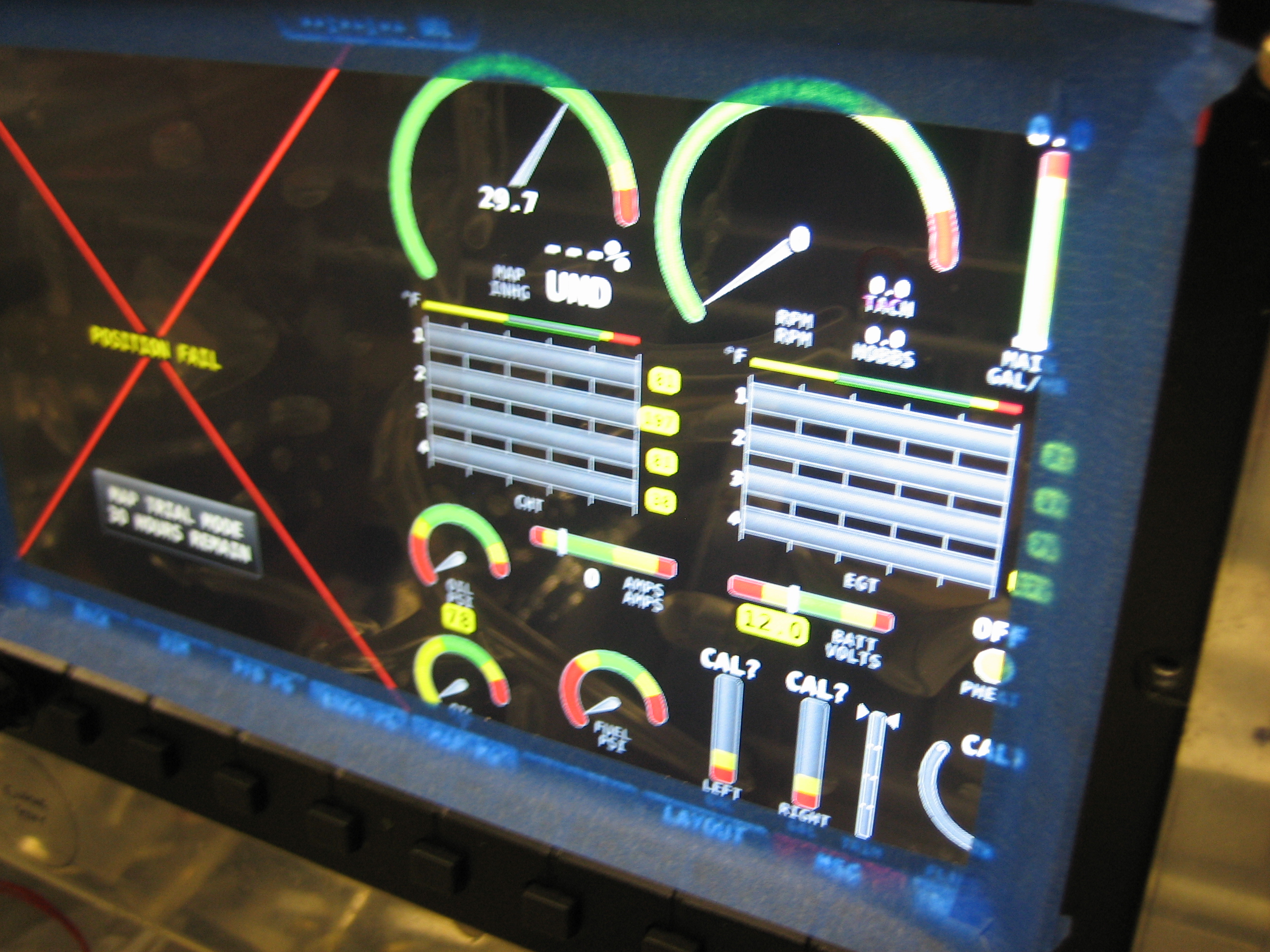
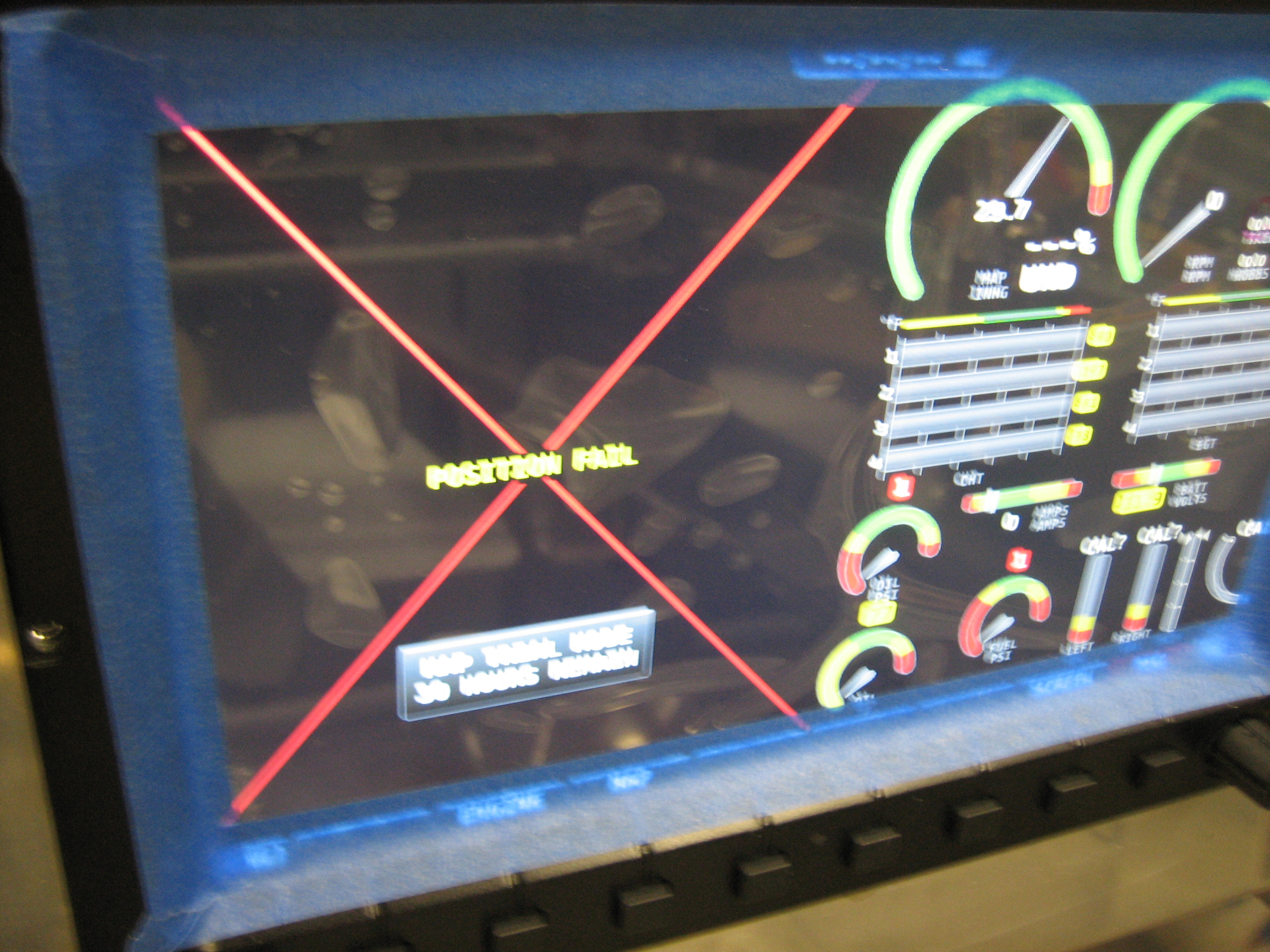
The right screen was showing a position fail indication, but that was expected since the serial ports haven’t been hooked up on the right screen yet.  The engine monitor seems to be working properly.  The manifold pressure is showing 29.7 inches of mercury.  The oil temp, #1 & #3 EGT/CHT temps and battery voltage are also indicating correctly

After a software update and reboot, the left screen has a valid GPS fix which caused the PFD to start showing synthetic vision.

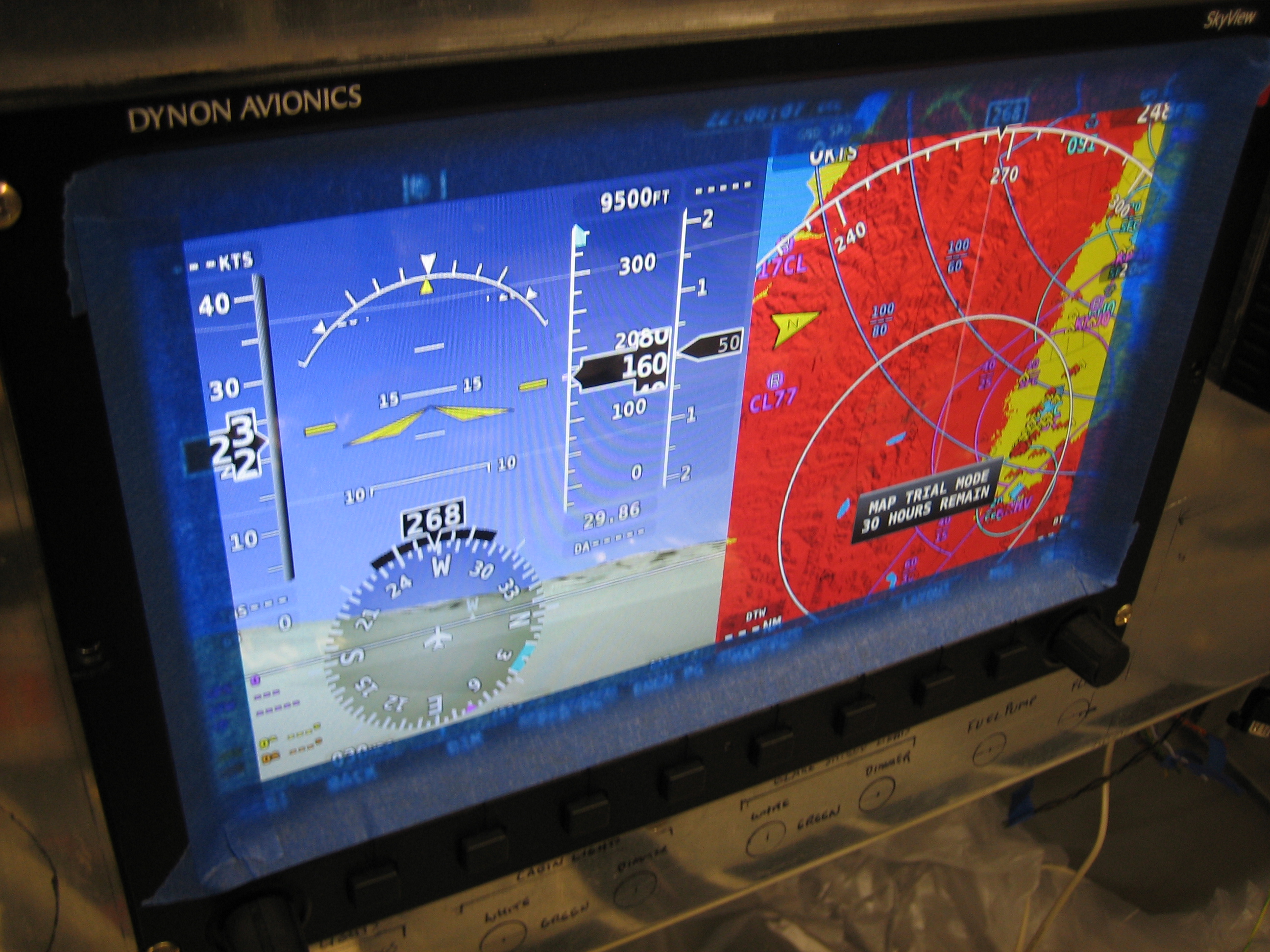
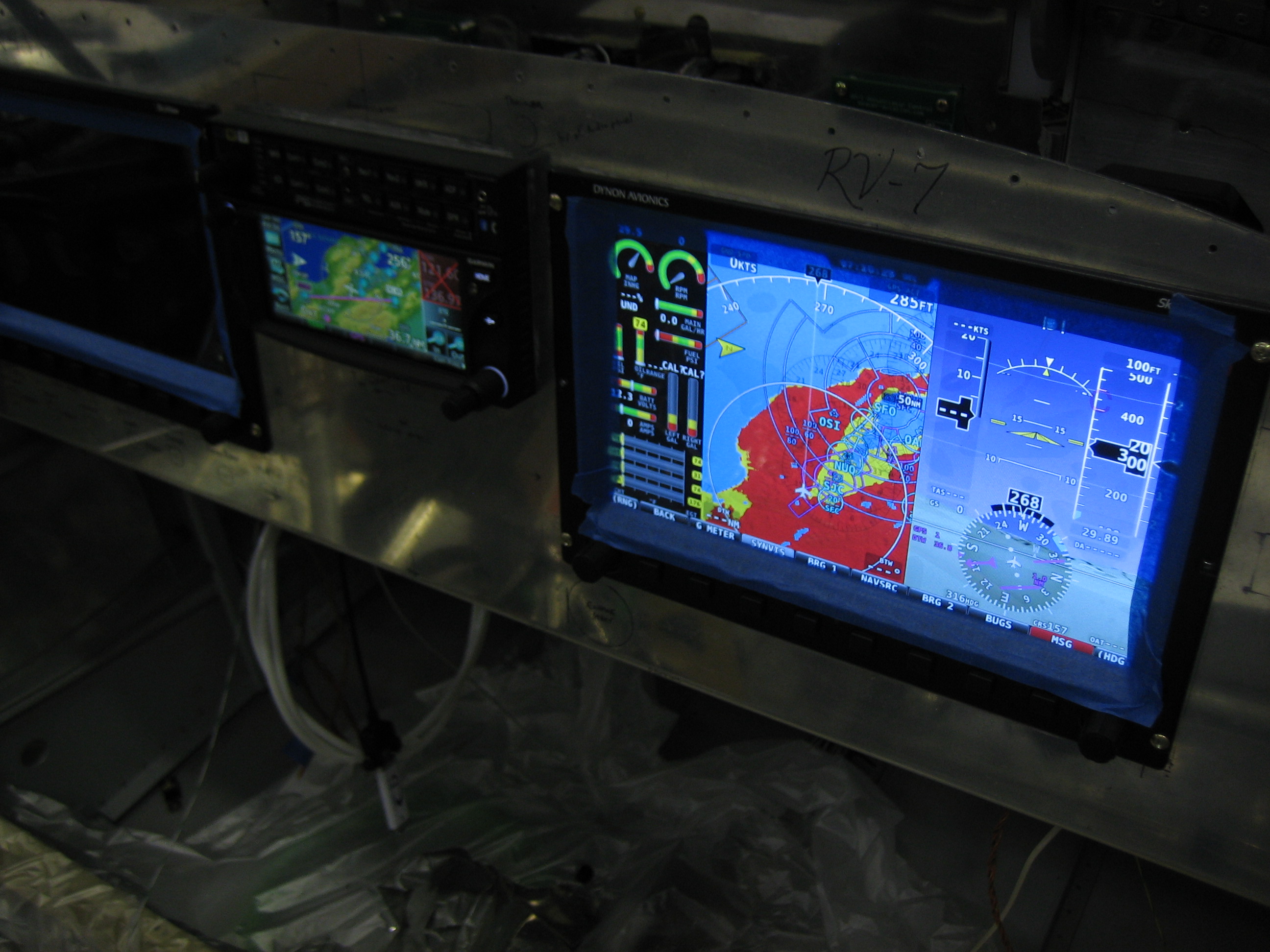
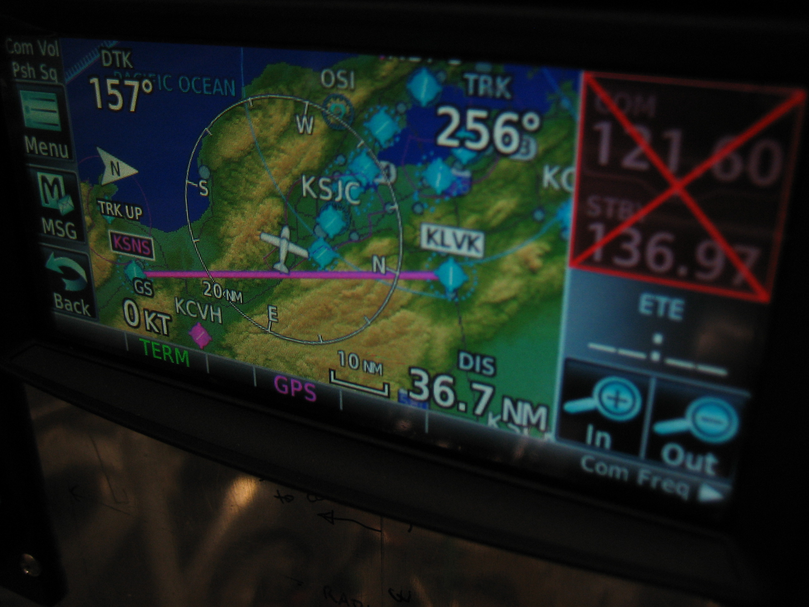
The right screen still has the position fail indicator though.  Time to hook up the serial ports.

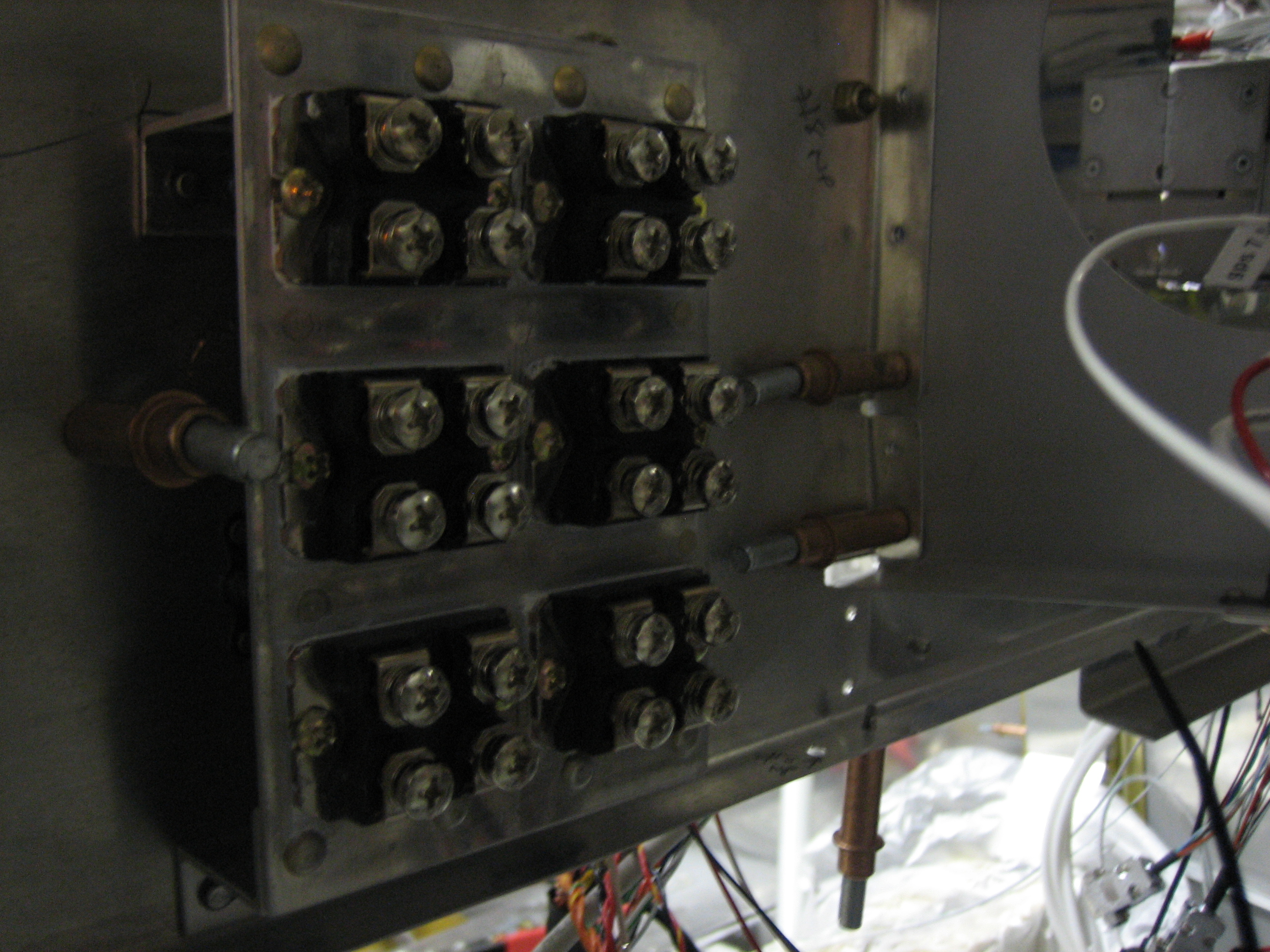
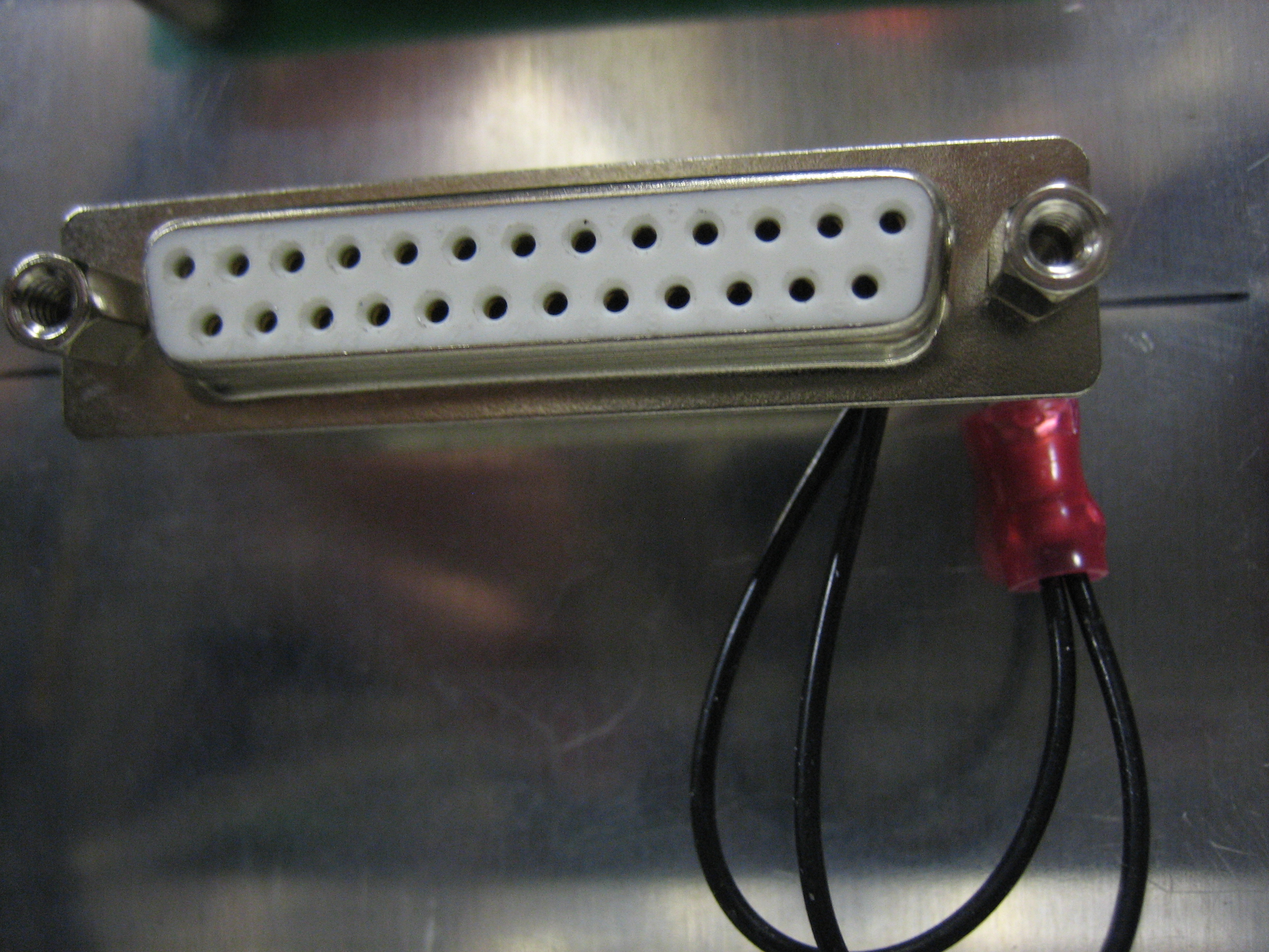
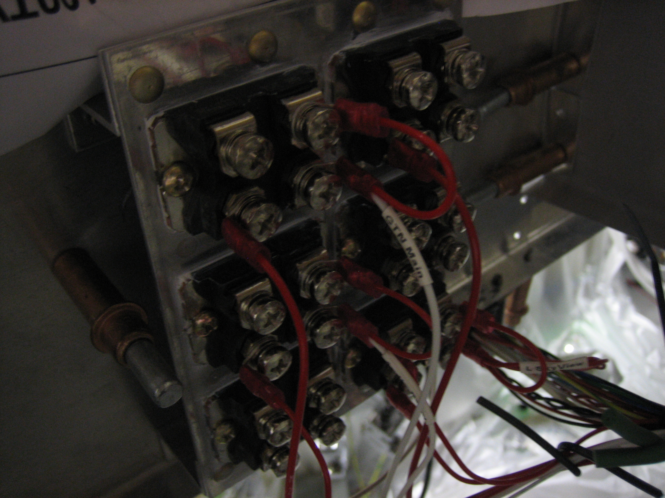
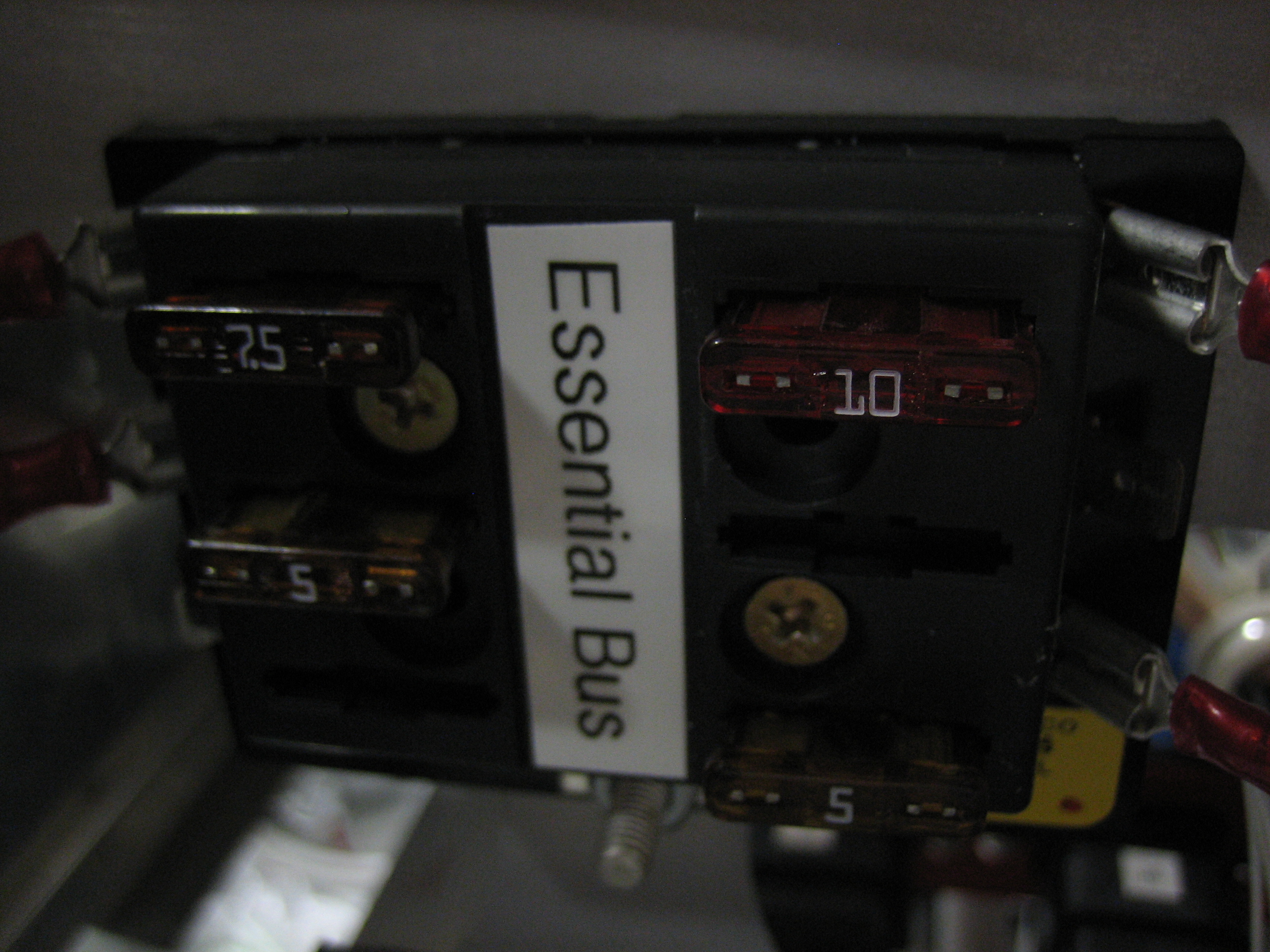
You can see that all of the connections on the top two connectors are identical.  The SkyView installation manual says that all of these connections should be shorted together between the two screens.  By hooking them up to the same pins on separate connectors, this happens automatically.  For example, the rightmost pins on the top and bottom row of each connector are for the #1 serial TX & RX lines.  Since both displays are connected to these pins on different connectors, their TX & RX lines are shorted together.  On the third connector down, you can see the transponder serial lines are connected to these same pins.  This allows both displays to send and receive data to/from the transponder.

After hooking up all of the serial lines from the right screen, both displays now have position data.

Fired Up Audio Panel and GTN 635

I stopped by the avionics shop this morning and had them swap a couple of audio inputs in the harness before I started wiring it into the airplane.  After work, I installed the connectors in the back of the trays and ran all of the ground lines.  I temporarily hooked up the power lines to the battery buss and installed some fuses to fire them up.  The map page showed No GPS Position, but that wasn’t surprising since I hadn’t connected the GPS antenna.

I installed a BNC connector on the COM antenna cable and a TNC connector on the GPS antenna.

I also plugged in the SD card and updated all of the databases.  They’re all current (at least for a few more days).

Even in my garage, the GTN had no problem acquiring 6-7 satellites within just a few minutes.  Subsequent restarts allowed the GTN to locate itself much faster since it already had an idea where it was.  The red X over the COM frequencies is because I didn’t plug in the fuse for the COM power line.

I had to fire up the SkyView screens to get an idea what the whole panel will look like.  The SkyView and GTN aren’t talking to each other yet, but there are only a handful of wires to hook up to make that happen (ARINC and serial).  The only other GTN wires that need to be hooked up are the serial outputs to the transponder and ELT as well as the dimming wires.

Connected SkyView and GTN 635

I connected all of the unswitched audio inputs from the audio panel to the interconnect bus along with the GTN serial output lines to the ELT and transponder.  I also connected the ARINC-429 TX/RX lines from the GTN to the SkyView ARINC converter box (along with the #1 GTN serial line).  The only harness wires left to connect are the dimming wires and headset jacks.

I spent a little time configuring the ARINC and serial connections on both the GTN and SkyView.  Now, with a simple flight plan entered into the GTN from KLVK on the right to KSNS on the lower left…

The HSI on the SkyView correctly shows that the course is behind me and that I need to turn left to head toward the destination.  Using the graphical flight plan editor on the GTN, I can drag the course line to a new location and the HSI on the SkyView updates immediately.

Received Isolation Diodes

Six of my devices will be connected to an essential bus in addition to the VP-X.  This provides an alternate power path for the most critical flight instruments and eliminates several single points of failure in the electrical system:

  • Master switch
  • VP-X
  • Master contactor
  • Various wiring downstream of the master contactor

The essential bus pulls power directly from the battery bus through a high current switch and into another fuse box.  Since there are two power paths for each device, I need to use a diode in each supply line to prevent back feeding power through either the VP-X or the essential bus fuse box.  A common cathode schottky barrier diode pair in a TO-247 case would be perfect from a power standpoint, but there are two problems with those devices.  The first is that the case is electrically connected to the cathode, so it must be insulated from the heatsink with a mica washer.  The second problem is that the TO-247 leads need to be installed in a circuit board and the connections must be soldered.  Instead, I chose these schottky barrier diode pairs in an ISOTOP package.  These will be perfect for the job.  The case is electrically isolated from the diodes, so I can mount these directly to the subpanel to ack as a heatsink.  They’re also rated at 40A continuous (per diode), so I won’t be anywhere near the thermal capacity of the diodes.  The only downside to these devices is that the cathodes must be connected externally, but that’s a minor issue.

The six devices that will be connected to the essential bus are:

  • Left SkyView Screen
  • Audio Panel
  • GTN Main Power
  • GTN COM Power
  • SkyView Autopilot Servos
  • TruTrak Gemini

Here are the diode packs I’m using.  I found them at mouser.com for about $25 each (I need 6).

I also installed a WDG3 adel clamp below the ARINC-429 converted box to support the wires and keep them from rubbing the subpanel.

Finished Cutting Instrument Panel

I’ve been pretty sick the past couple of days, but after sleeping 12+ hours a day, I was feeling quite a bit better by tonight.  I came out to the garage with the intention of finishing cutting all of the holes in the instrument panel.  I needed to fabricate the annunciator light bar first so that I knew what size hole to make.  I cut a scrap piece of 0.063″ and drilled a series of holes in it.  I left little ears on each end so that I could attach nutplates.  This whole piece will be installed from the back side of the panel so that the panel can be removed if necessary.  I printed up some labels on regular printer paper and cut them out to fit inside the lights.

I picked up an instrument punch from ATS just to cut this one hole ($120 including the hole drilling template).  That’s a lot for just one hole, but this edge will be visible since the Gemini installs from behind.  Hopefully, I’ll get more use out of it down the road.

I spent a little while cutting the hole for the engine start button.  I’m mounting it just above and to the right of the mixture control so that it’s easy to reach while starting.  It will be disabled by the VP-X after the engine is running, so it’s no big deal that it’s within reach of the passenger.  I still need to figure out how to anchor this button in the panel since it was designed to clip into a Honda S2000.

I also drilled all of the holes below the left SkyView screen.  The smaller ones are for a couple of dimmers.

I also drilled all of the holes in the upper left for the switches there.

This is the slot for the annunciator lights.  The small holes on either side are for some #6 screws that will attach the annunciator light bracket.  The larger holes are for a push-to-test button and a dimmer.

To the right of the right SkyView screen are holes for two breakers, the hobbs meter and ELT remote.

Installed Remaining Components in Instrument Panel

I soldered wires on all of the annunciator lights and push-to-test button and bundled everything up.  I had to rotate the dimmer to clear the radio stack.

I’ll replace the red button cap with a black one, but other than that, this is done.

By mounting the lights from the back, all of this can come out as a unit when the panel is removed for painting.

I figured out how to secure the start engine button.  I riveted a 1/16″ bracket to the instrument panel just to the left of the hole on the back side.  The leg that sticks out is bent towards the hole slightly and has a beveled edge.

When the button is installed, the bracket catches a nub on the side of the button.

You can see that the button is tight against the panel when hooked behind the bracket.

I fabricated a small removable clip for the other side that will hold the clip back when held in place.  You can see that it also has a beveled edge to fit behind the spring on the right side of the button.  I was planning on keeping all of this together with a worm clamp, but a zip-tie does a great job.  I might just leave it like this.

All of the switches and breakers installed in the panel have an anti-rotation washer.  This has a tab on the inner edge that fits in a keyway on the switch and a tab on the outer edge that fits in a hole in the panel that keeps the switch from rotating.

Most builders fabricate a bracket that sits behind the panel with a hole for the anti-rotation washer, but the panel is thick enough that you can just drill part way through it on the back side.

I installed the breakers, hobbs meter and ELT remote.  I don’t have the correct screws for the hobbs meter and ELT remote, so I just installed them with some scrap hardware for now.

I also installed all of the switches below the left SkyView screen.  The hole in the middle is for a two-pole progressive transfer switch (2-10) like the three on the left.  It’s on order and should be here soon.  The switch on the right is a 2-7 for the flaps.  It is a momentary up and down switch that returns to the center when released.

Here are all of the switches in the upper left of the panel.  The lower left switch is for the essential bus.  The one above that that is brass colored is the alternate static switch.  The rest of them are 1-3 switches for master, ignitions, alternator and avionics.

Mounted Isolation Diodes and Panel Ground Block

I had been looking for a place to mount the isolation diodes for those items on the essential bus, but hadn’t found a place I liked.  I wanted to mount them to the subpanel or one of the subpanel ribs for heat dissipation reasons, but there’s not a lot of free space left.  They need to be mounted with screws that penetrate the mounting surface, so the other side of where they mount has to be free.  There was plenty of room on the back side of the right subpanel (behind the right SkyView backup battery, but only if I spaced them away from the subpanel a bit.  I fabricated this little mounting block out of some 0.063″ sheet and some z-channel.  This has a lot more thermal mass than the subpanel anyway, so it will help keep the diodes cool.  I mounted them all with some thermal paste to help heat transfer into the aluminum.

I installed nutplates on the back side in case I ever need to remove one of the diodes.

Nutplates are also installed in the z-channels so that this can be screwed in from the front.  Everything that installs onto the subpanel needs to be removable so that I can pull it out when I paint the interior.

I installed the essential bus fuse box just above the battery bus fuse box.  Each of the wires from the essential bus will run over to the isolation diode bank, so this is a pretty good location since it keeps the wiring runs short.

I also fabricated this little ground block that is installed under the avionics interconnect bus on the left side of the subpanel.  I soldered two 22AWG wires to all of the pins on the back side of this connector and then grounded it using one of the mounting screws.  All of the VP-X switches just sense ground (there is effectively no current), so there is no point in running individual ground wires all the way back to the firewall grounding block.

I ran ground wires to all of the switches that will be connected to the VP-X.  Now all I need to do is run wires from the other connectors on the switches directly to the VP-X and all of the switches should work.

Installed and Started Wiring Instrument Panel

I installed the instrument panel in the airplane this afternoon.  This was more of an ordeal than I thought because I intentionally left the angles long that attach the panel to the radio stack.  I had to remove them and cut them back so that they wouldn’t interfere with the annunciator lights and switches at the bottom of the panel.

First up is to wire the master contactor.  I used some 20AWG black wire (since this will go to ground potential when the master switch is closed) and ran this back to the panel.  I ran this through the right firewall penetration since that’s where I’m running all of my non-sensor wires, and this will carry a non-trivial amount of power.

This goes to the master switch and the other wire here goes back to the firewall ground block.  Most of the other switches on the panel will be grounded locally since they’re just sense wires for the VP-X, but like I said, this will carry a non-trivial amount of power so it goes back to the firewall.

With the battery hooked back up, throwing the master switch makes a nice satisfying clunk.  I confirmed voltage at the VP-X was correct and shut everything back off.  My goal is to get the VP-X providing power to all of the avionics within the next week.

Avionics Power Wiring

I rearranged a few pins on the VP-X based on some feedback I got from Vertical Power, then started wiring power to the essential avionics up through the isolation diodes.  The cathodes are the right pair of screws in each package, so they get connected together with a short loop of wire along with the wire to the device.  The left pair of screws in each package are the anodes and are for receiving power from the VP-X (upper left screw in each package) and the essential bus (lower left screw in each package).  I ran out of #8 ring terminals, or I could have finished this up tonight.

I wired up four of the six devices on the essential bus.  The ordering in the diode pack is the same as the ordering in the essential bus (e.g. upper left in both is the GTN main power, etc.)

Since I was wiring the essential bus, I went ahead and hooked up the essential bus switch in the panel with some 12AWG wire.

The essential bus switch is a locking switch that has to be pulled out to turn on or off.

Installed Real Vertical Power VP-X Pro

I started running through the VP-X install checklist.  I verified all device power lines and VP-X ground lines.  I also confirmed all switches ground properly.  Afterward, I removed the VP-X Pro blank box and installed the actual VP-X Pro box.

After hooking up all of the connectors, I threw the master switch and verified the VP-X powers up.  These are the lights on the ethernet jacks.