Installed Roll Bar

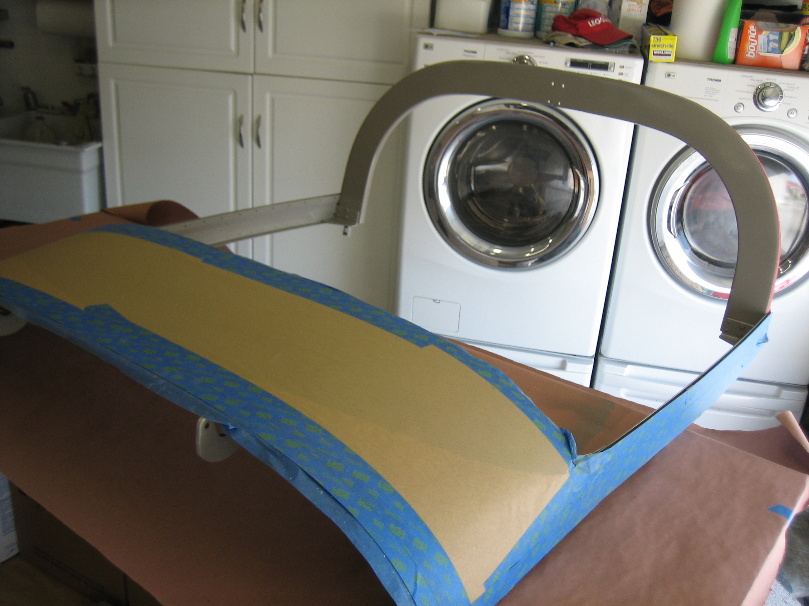
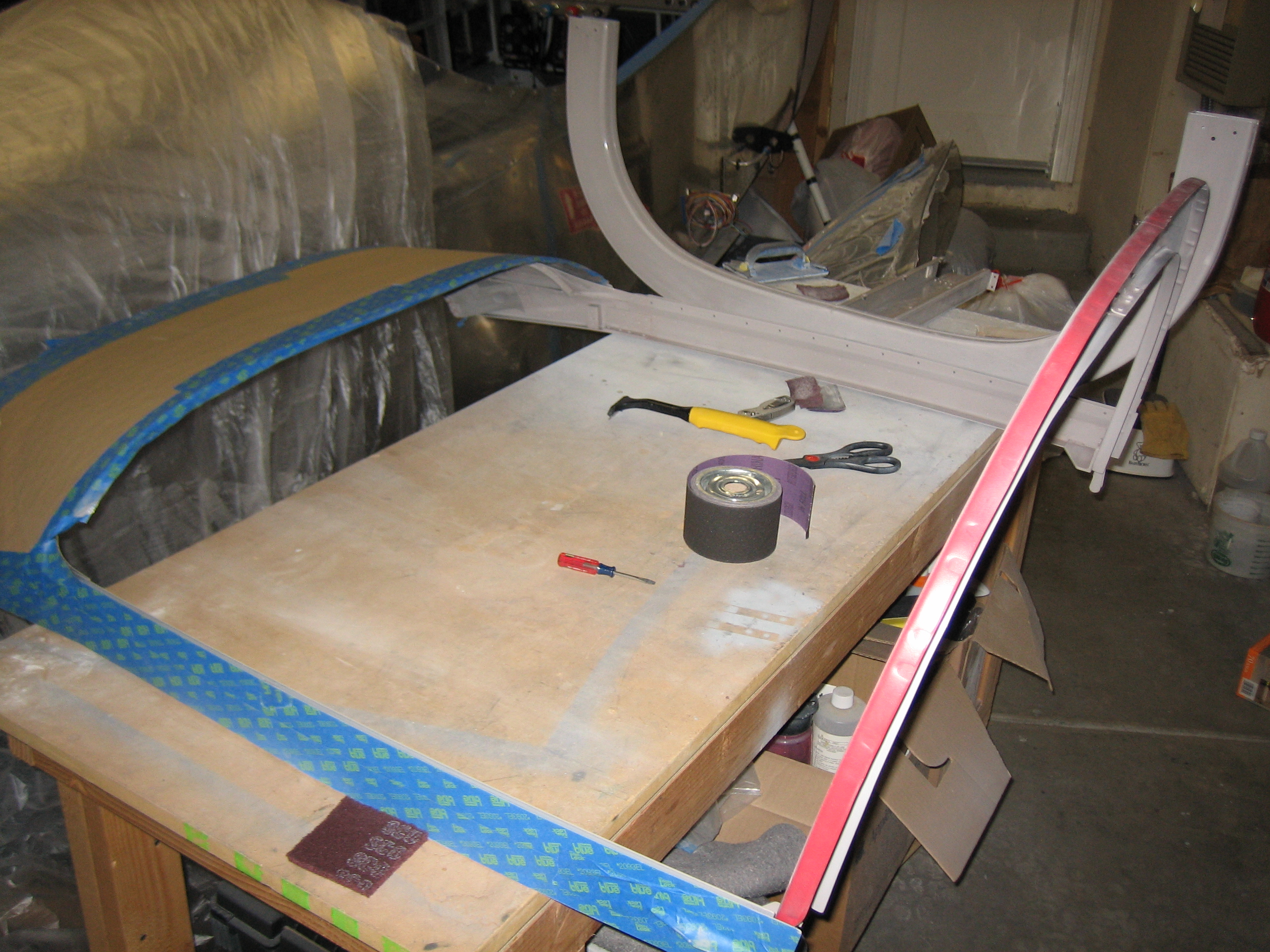
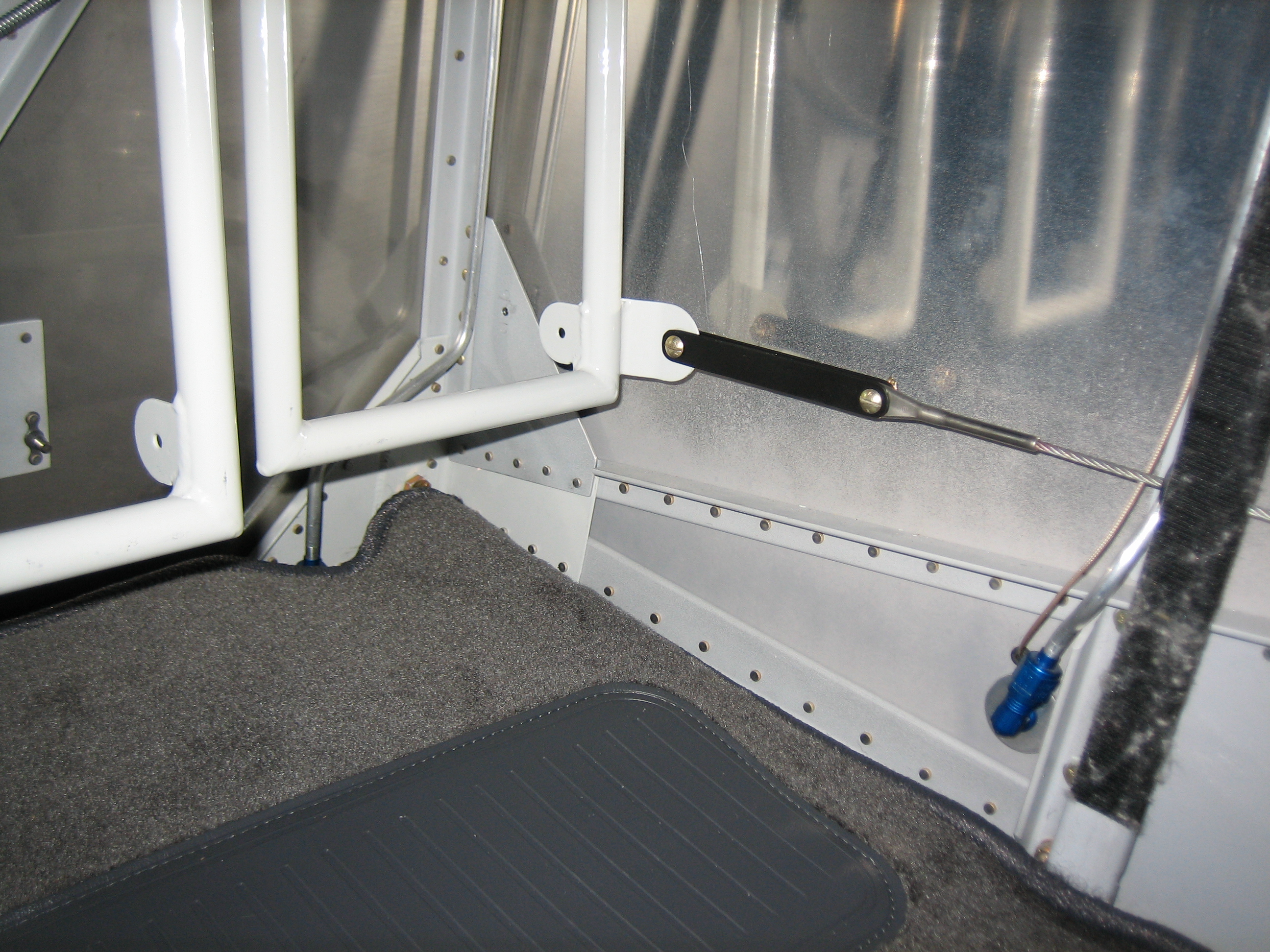
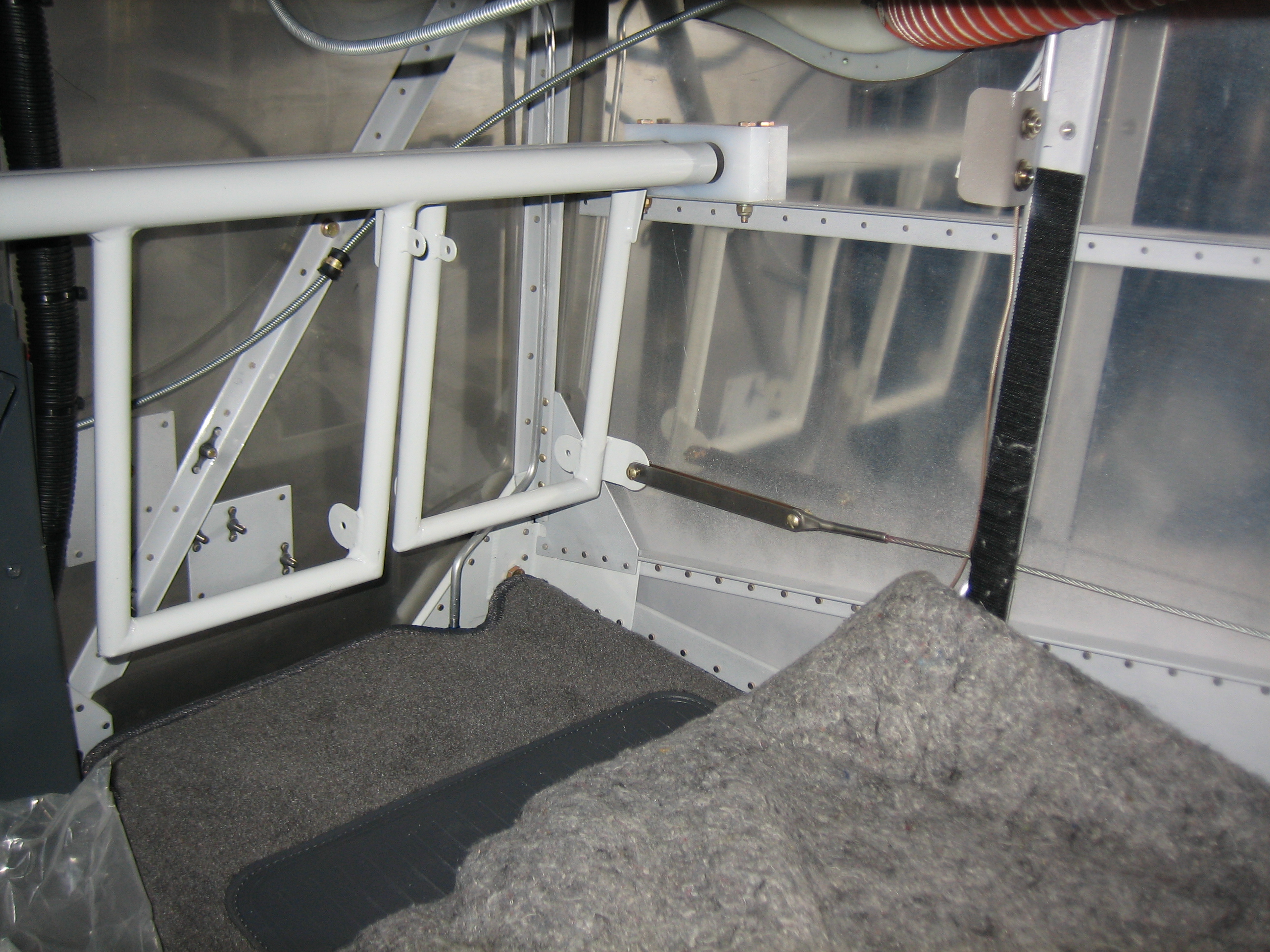
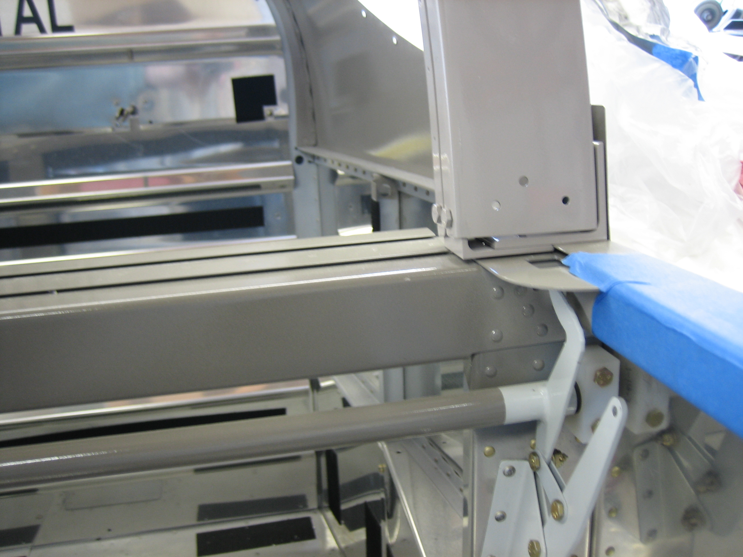
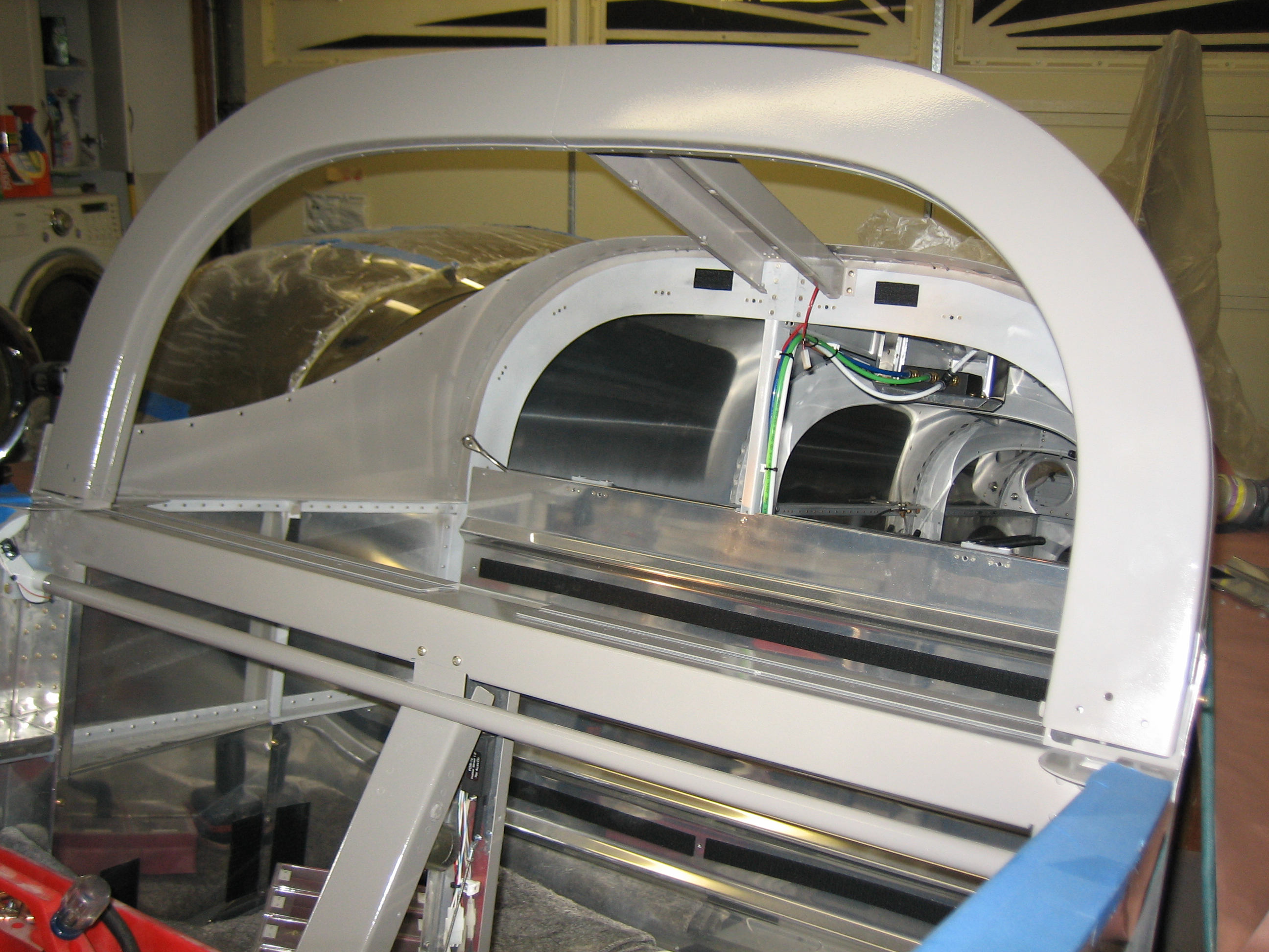
I installed the roll bar for good tonight.

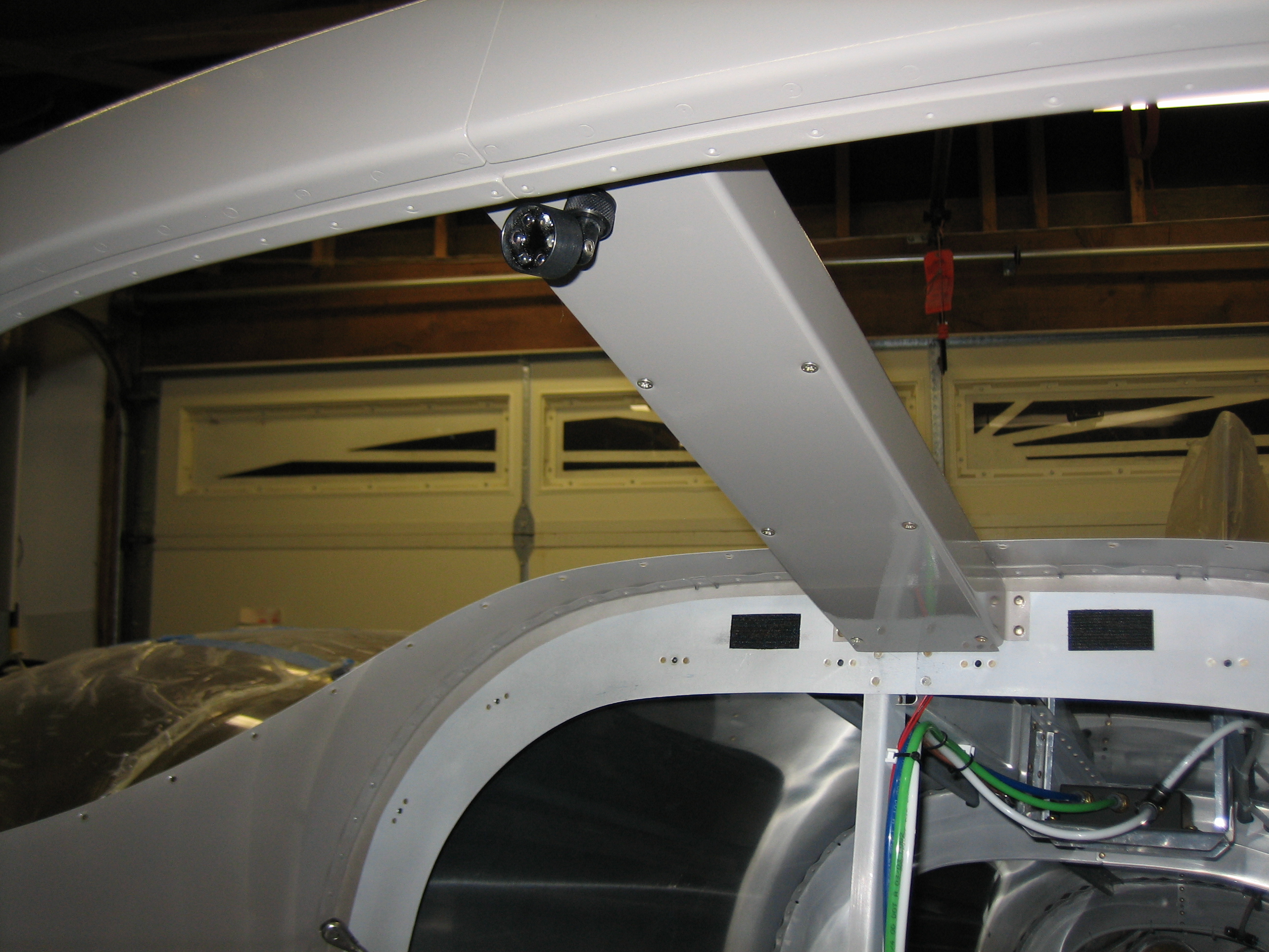
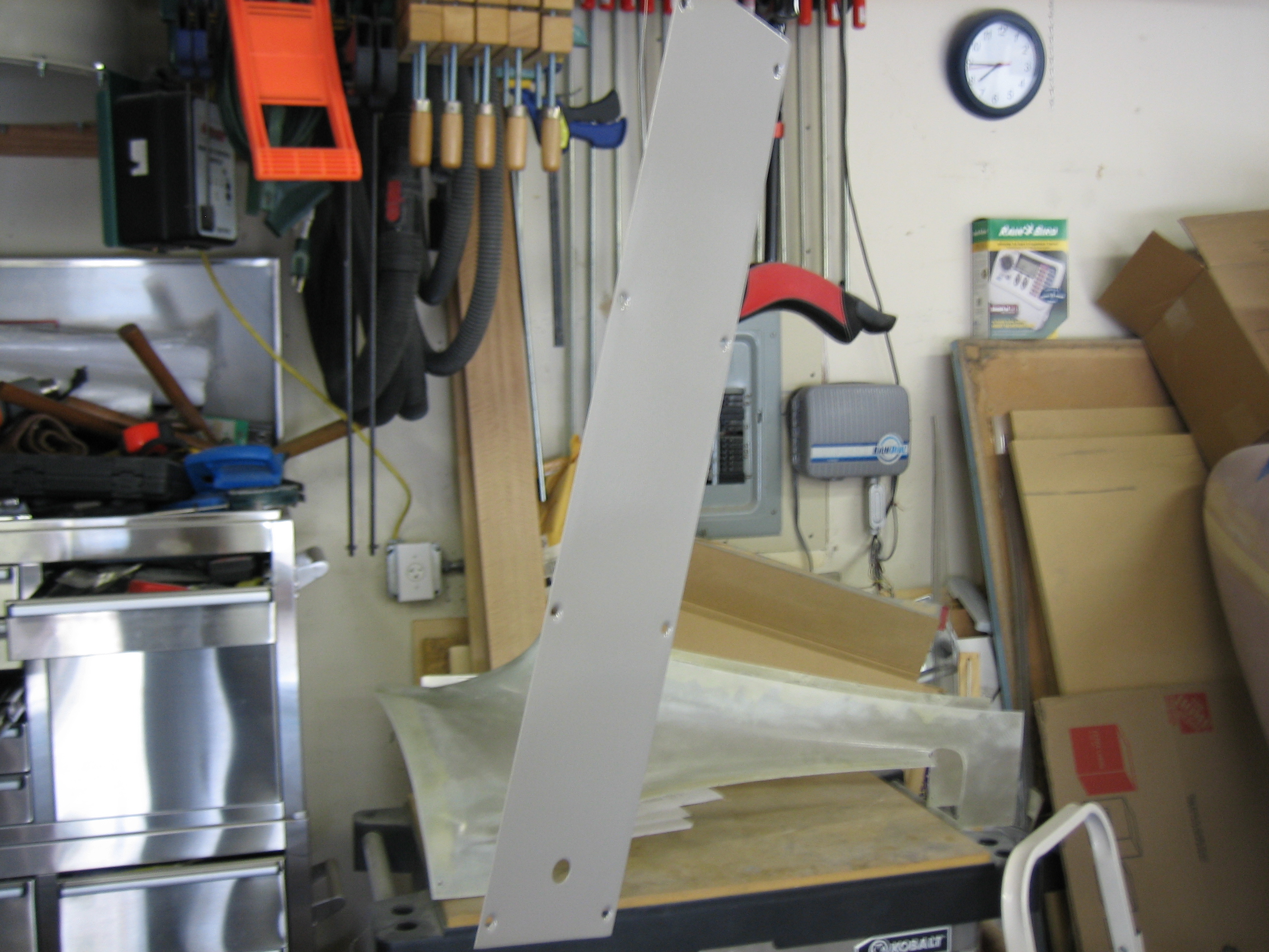
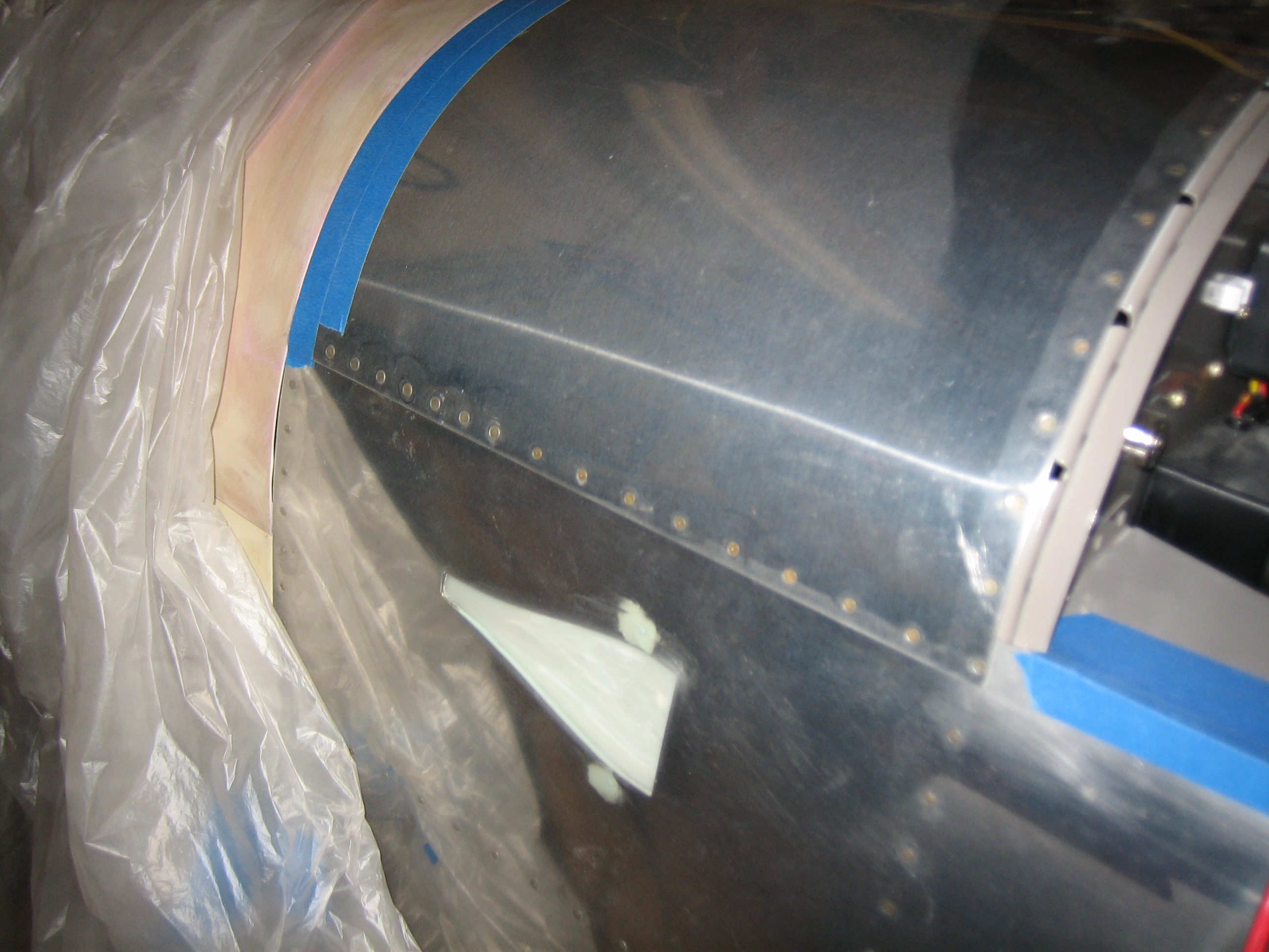
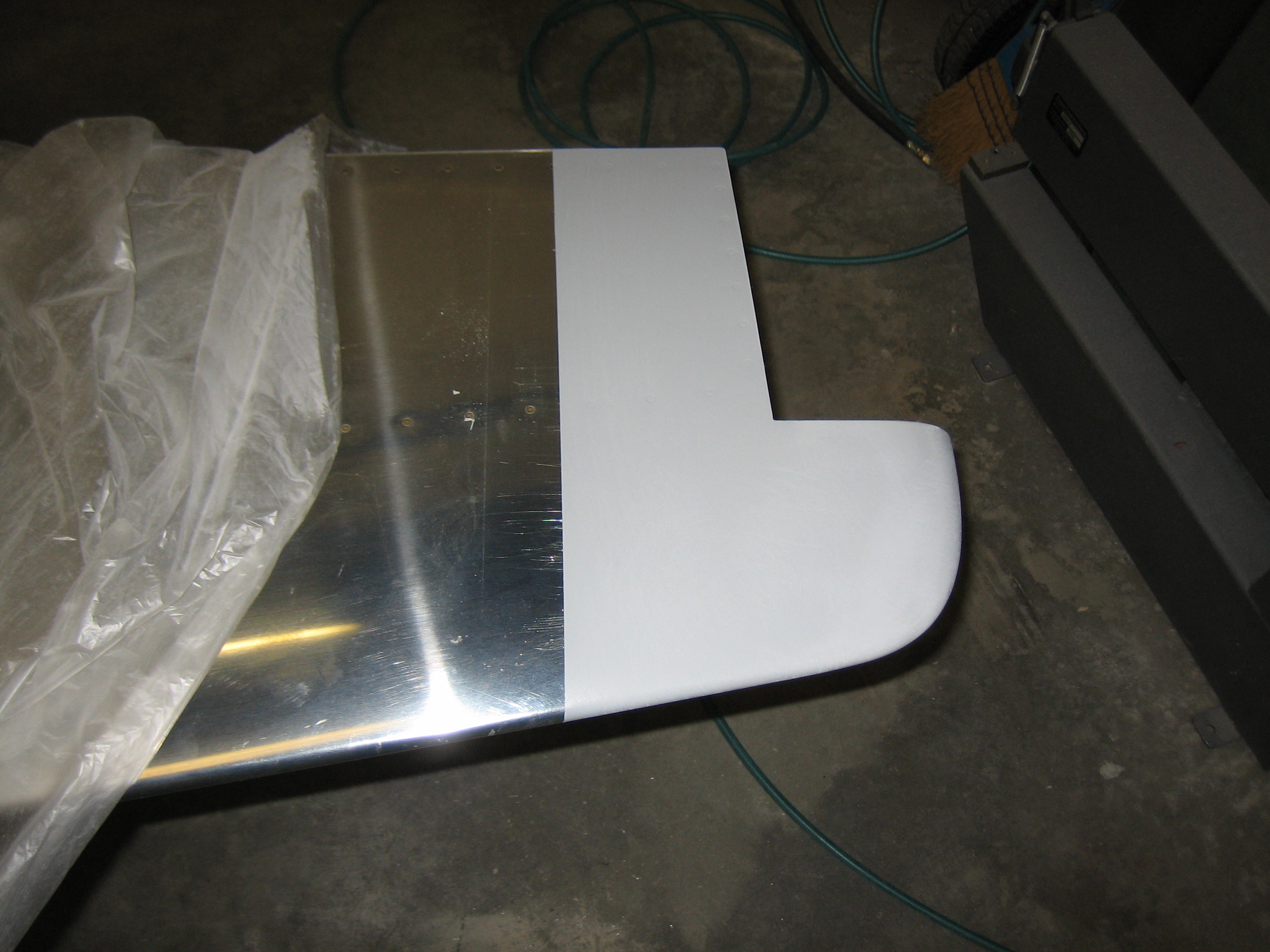
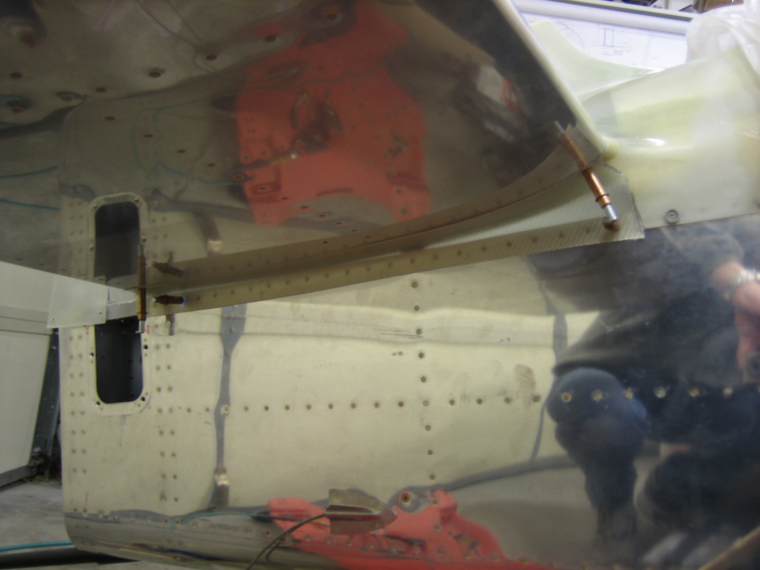
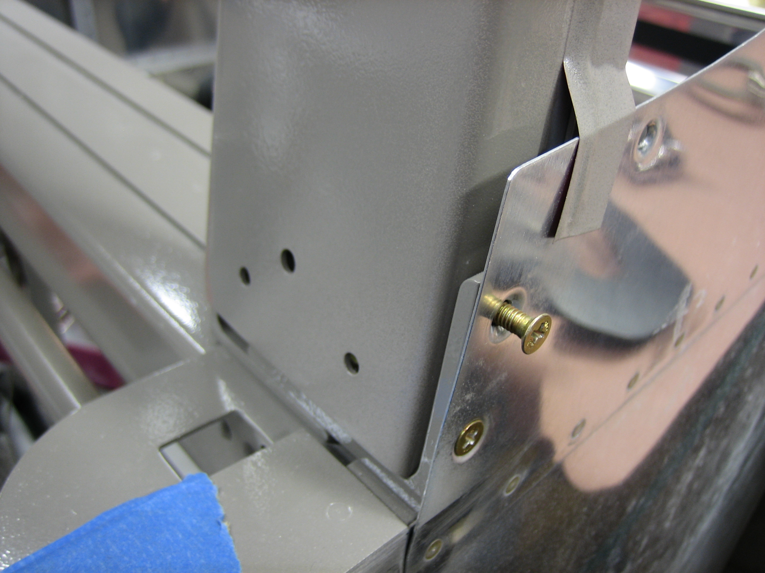
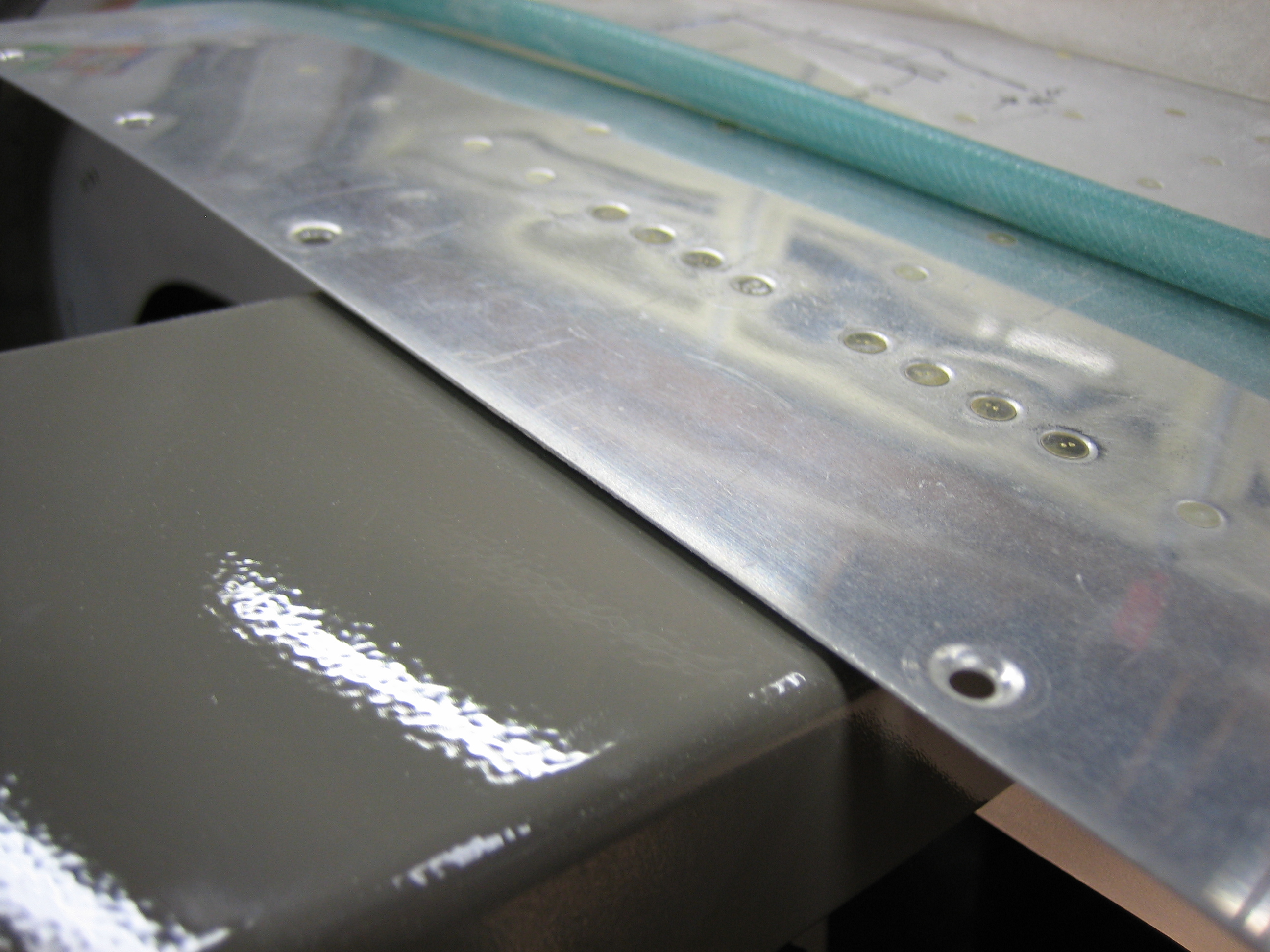
Remember to install the AN509-10R10 screws that are hidden behind this skin before installing the roll bar.  I only installed the lower AN509-8R8 screw completely since I need to be able to flex this skin back to install the rear window.

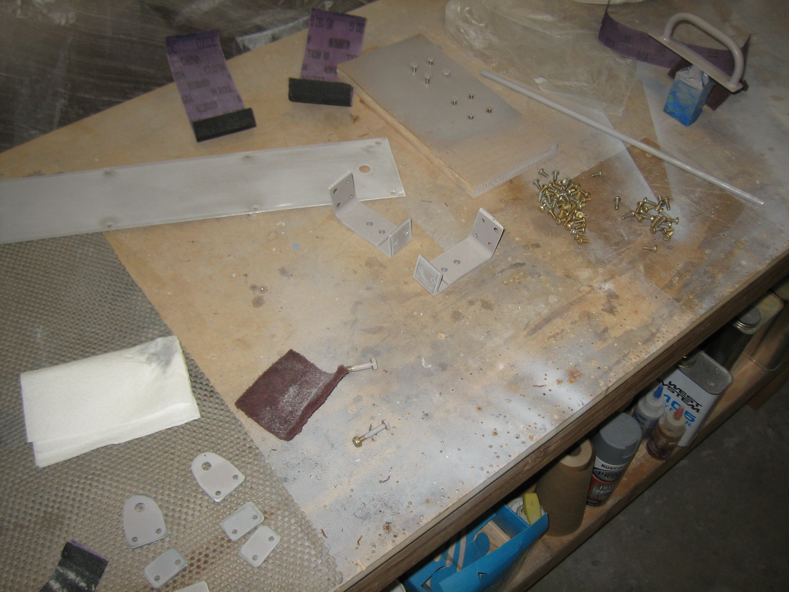
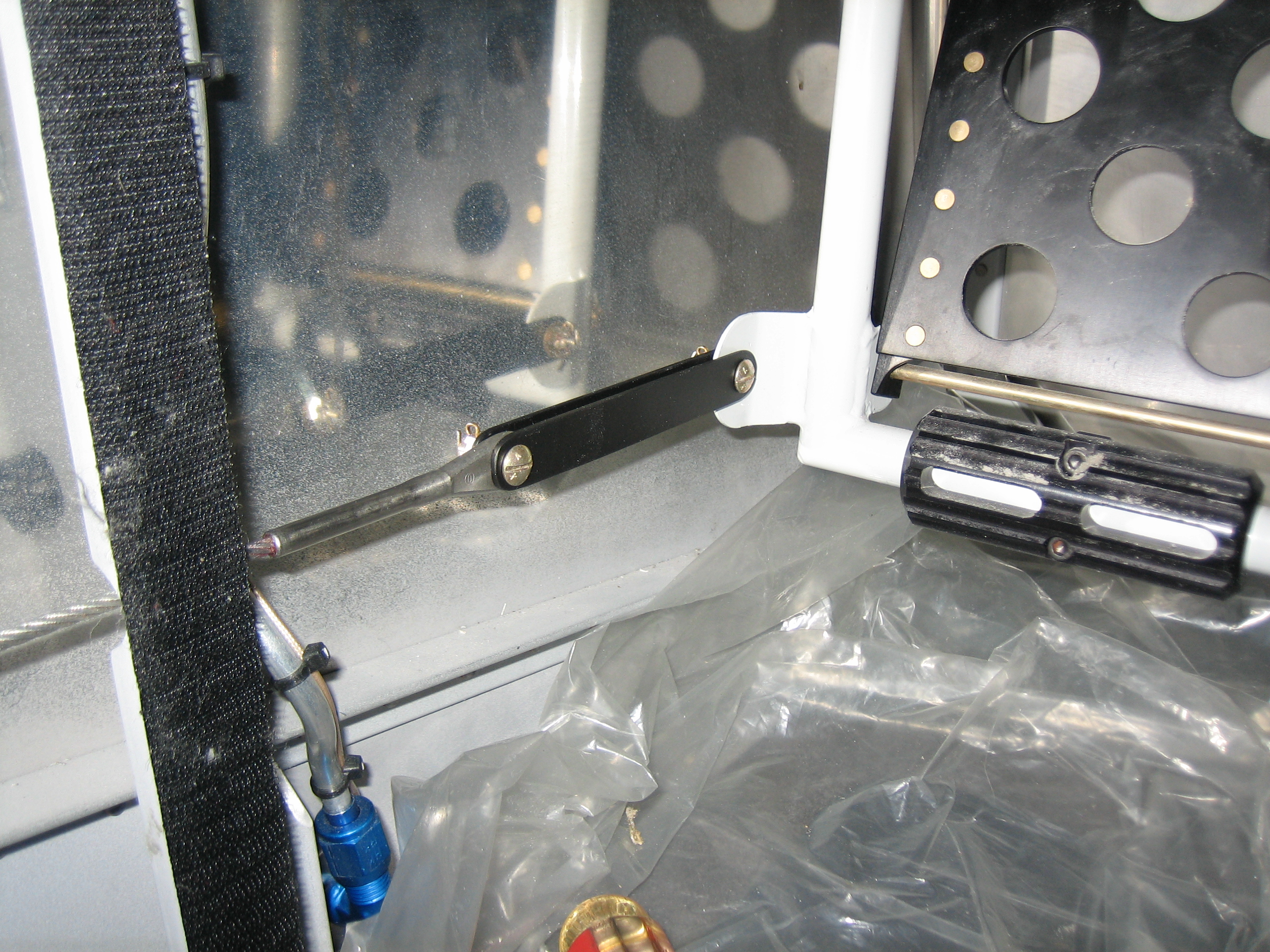
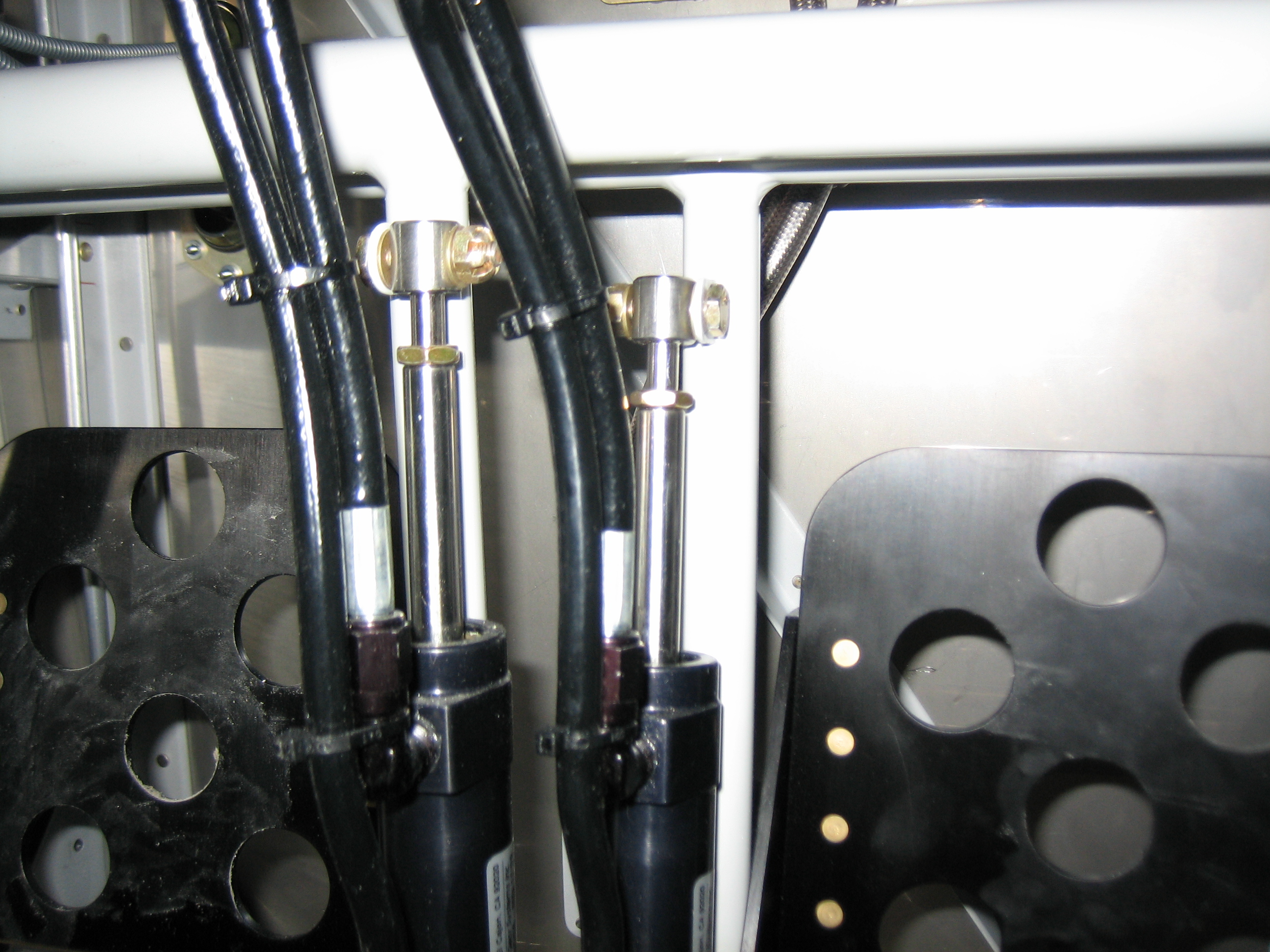
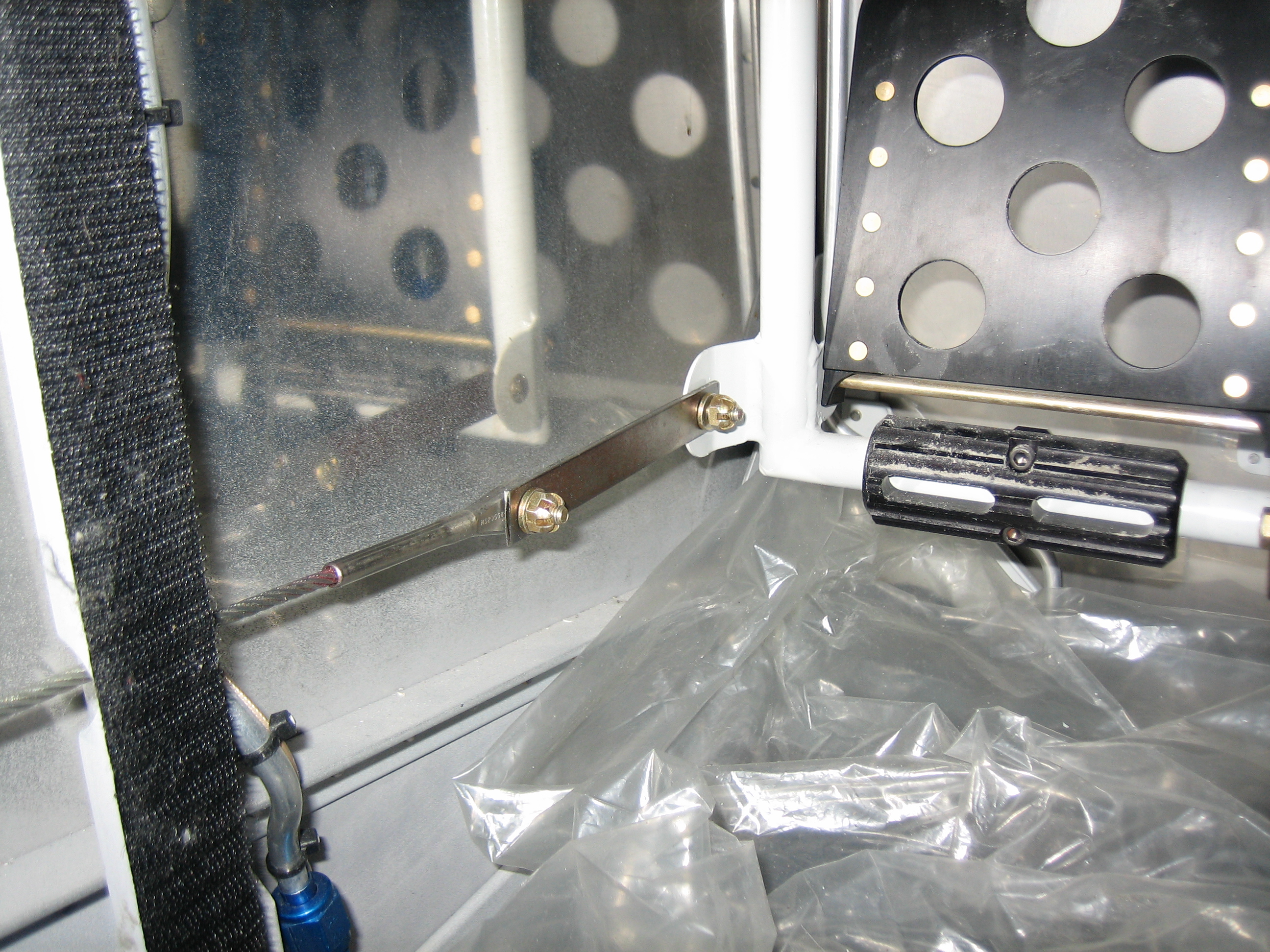
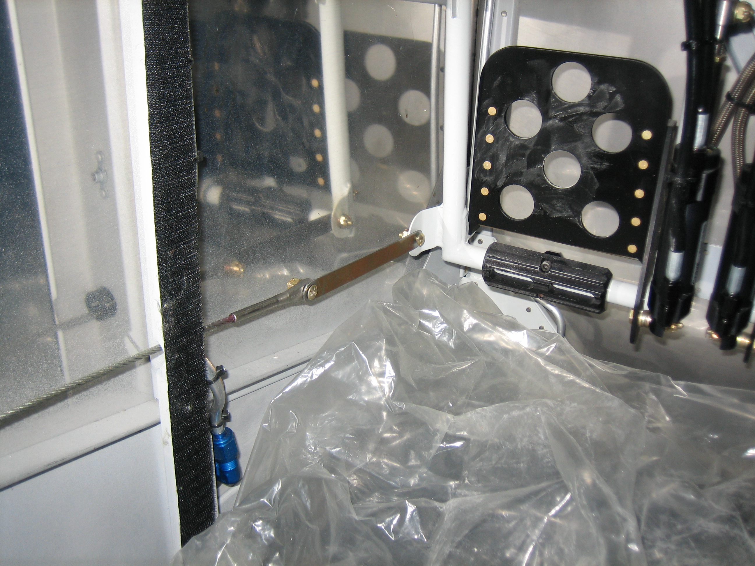
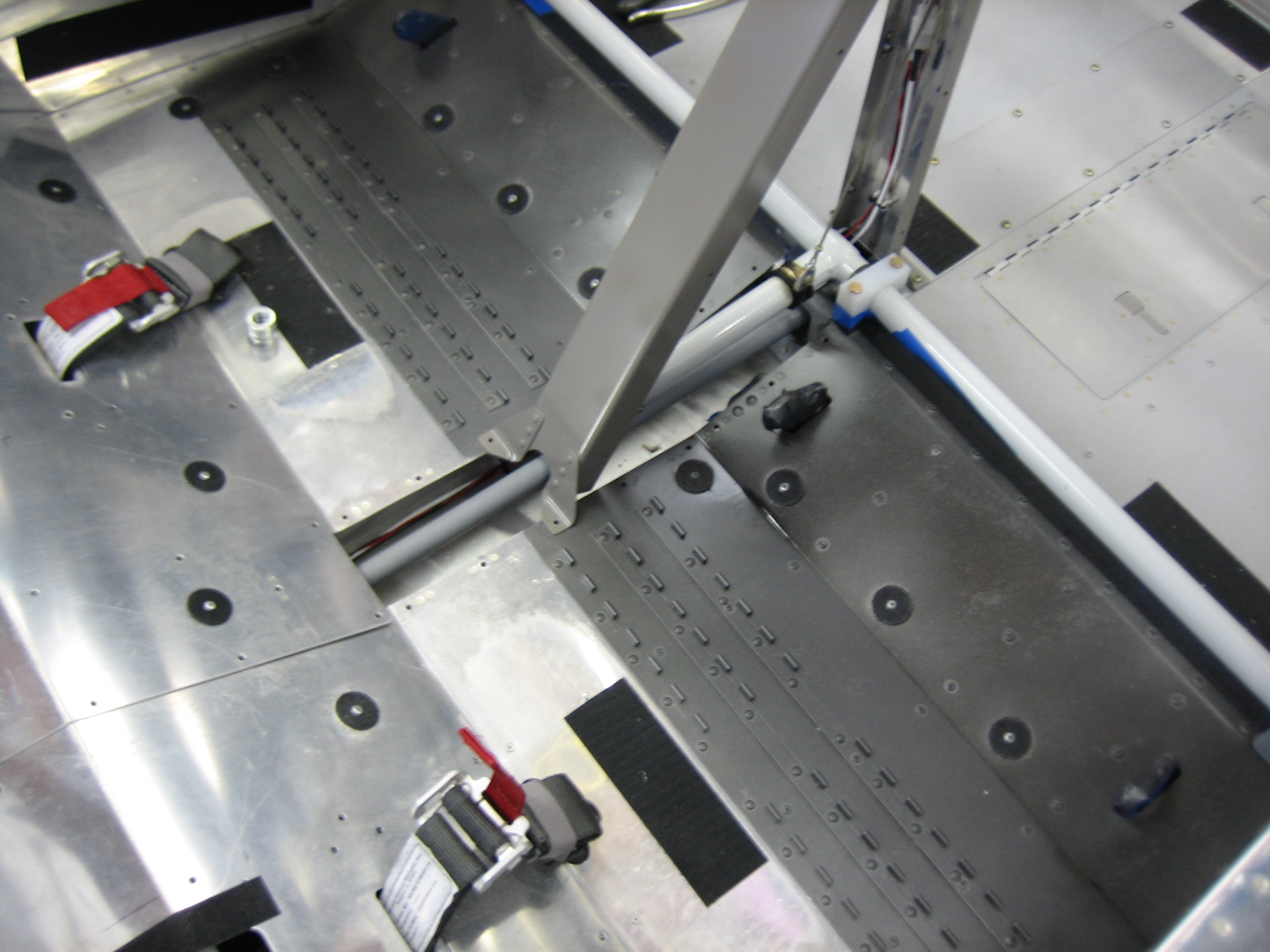
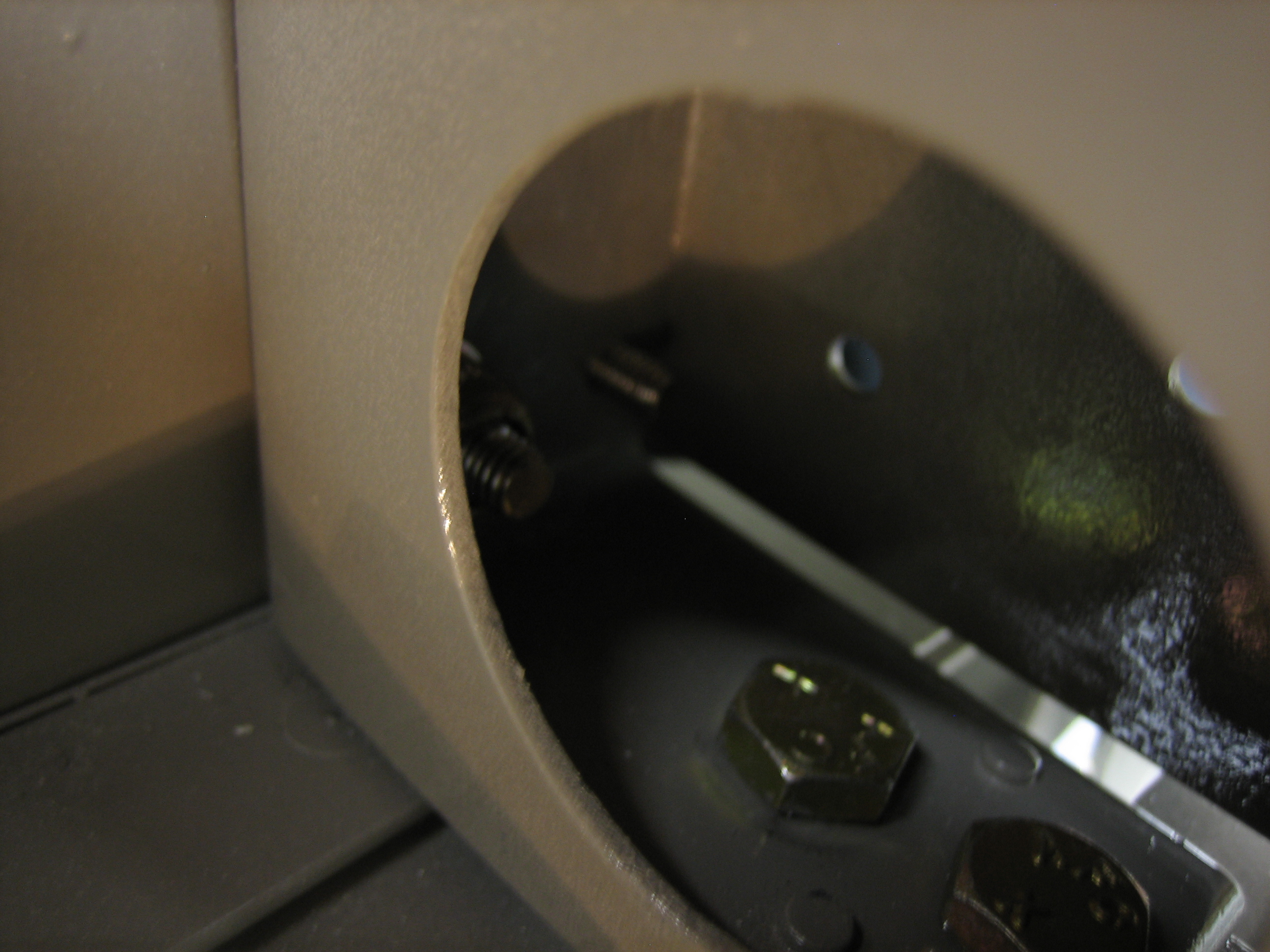
There are a bunch of fasteners to install inside the roll bar.  It’s a pain to reach in here, but I managed to get everything in place without too much trouble.

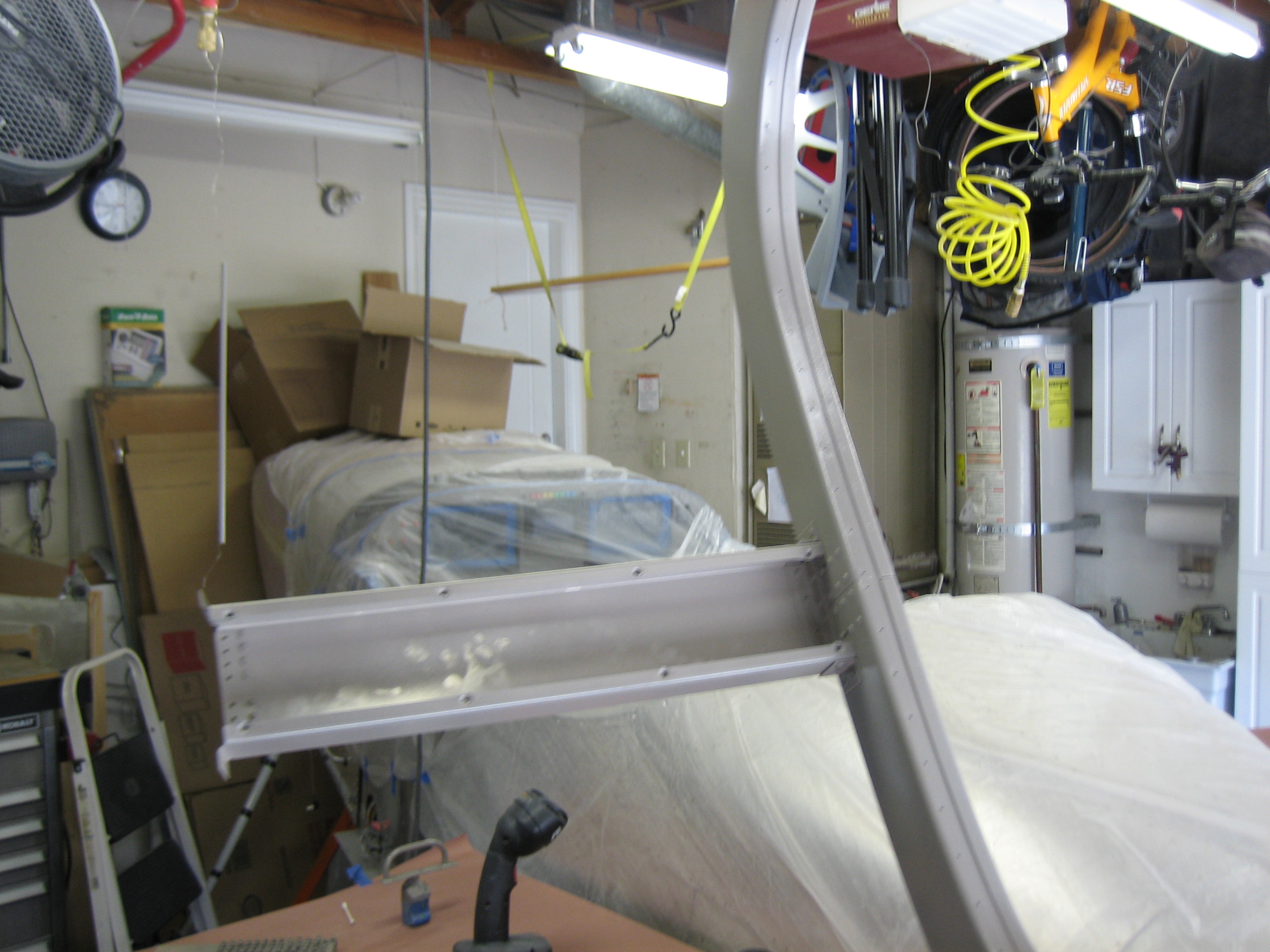
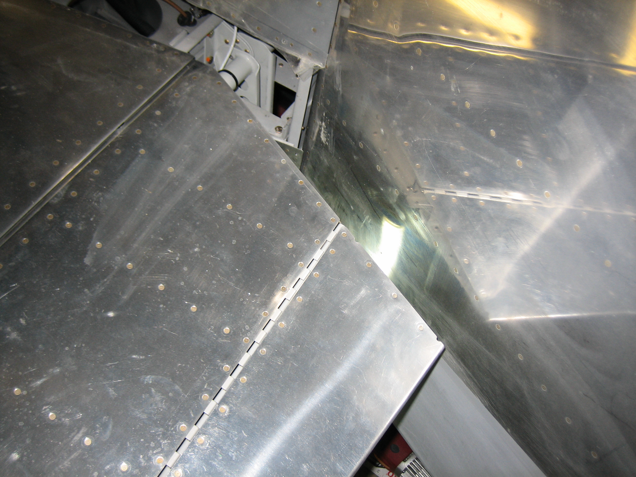
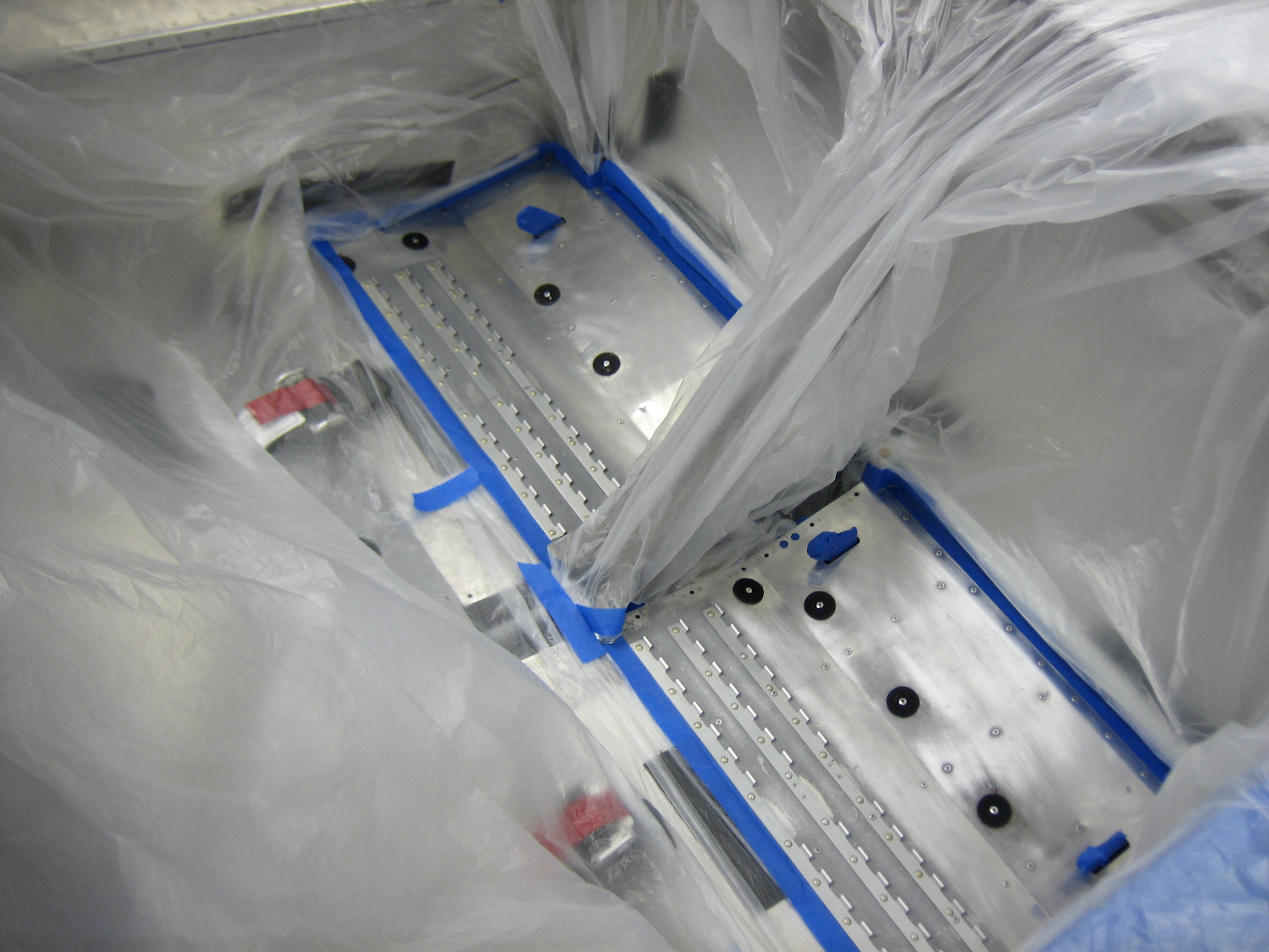
I also shot and bucked the rivets that attach the roll bar support channel to the aft fuselage.  There are 8 AN426AD4-7 rivets tying the top skin, baggage aft wall bulkhead and roll bar support channel together as well as a few more AN470AD4-4 rivets tying the channel to the bulkhead.

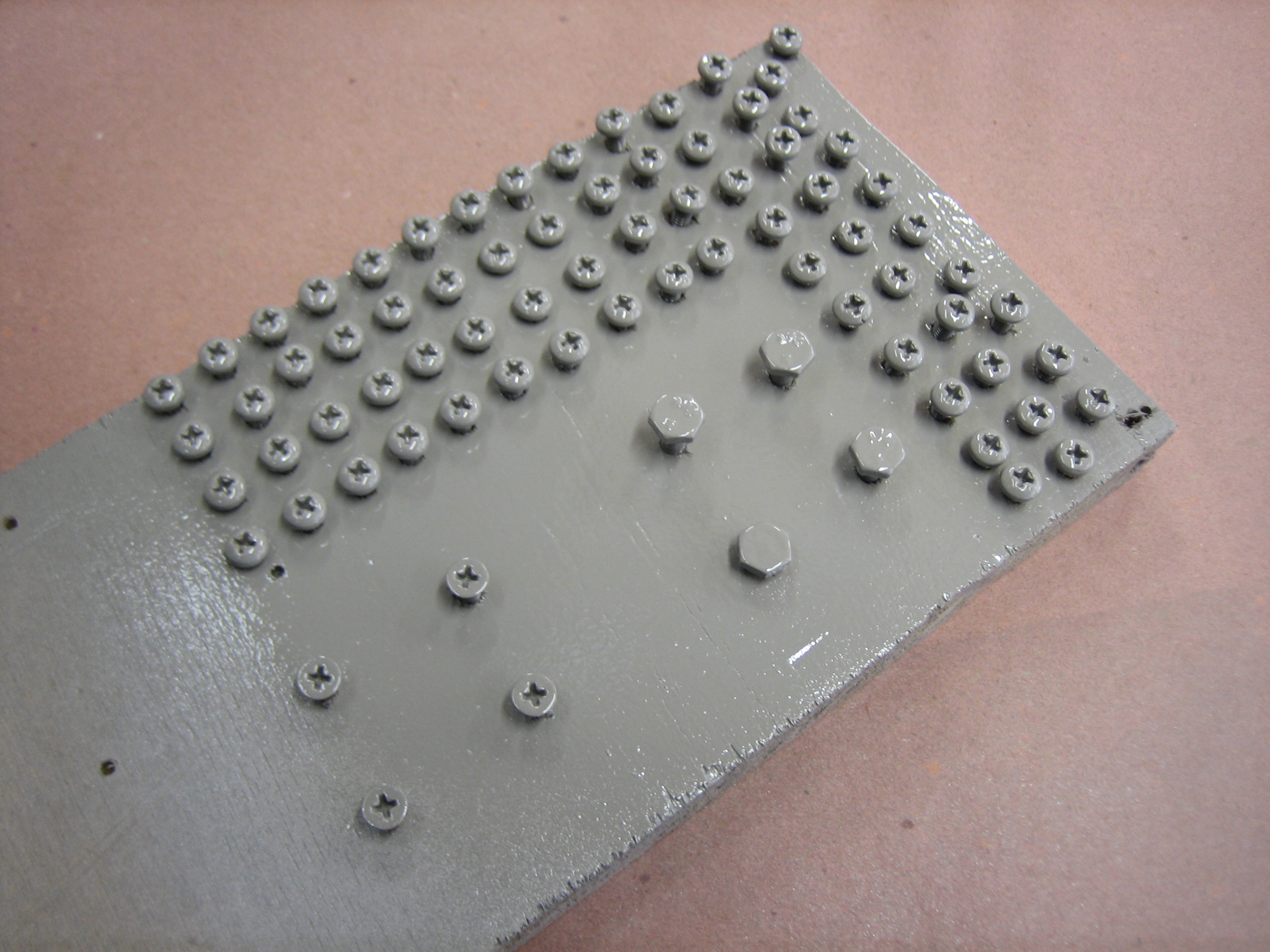
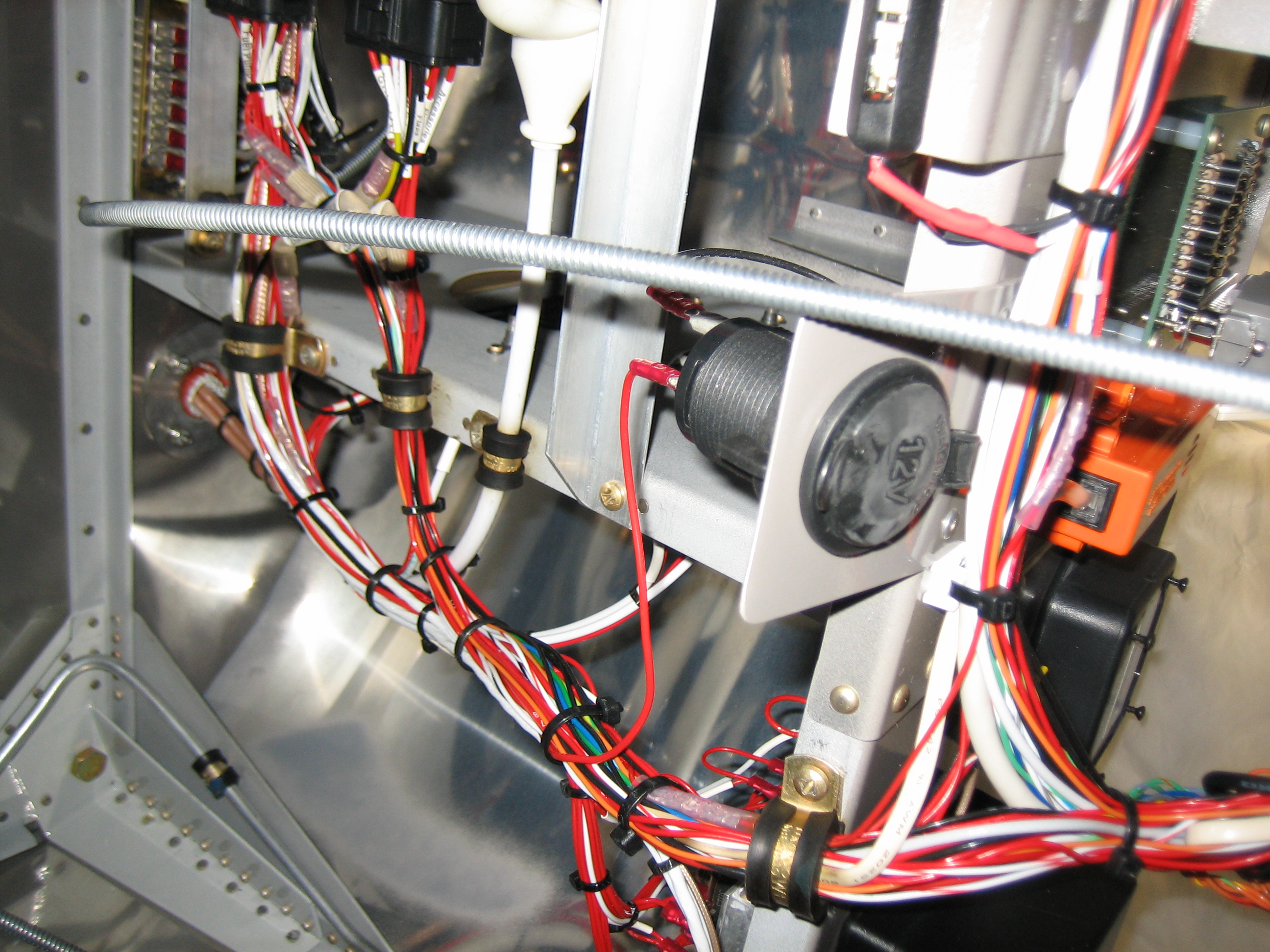
Finally, I installed the canopy support channel cover for good.  I need to paint a few of these AN509-8R8 (or shorter) screws and replace these at some point, but that can wait for now.

Sanded Canopy Components

I received the correct paint color from Stewart Systems (I hope), so I sanded down all of the components I previously painted.  Some of the components had some dust or overspray on them anyway since I sprayed them flat, so I’m glad I’m repainting them anyway.

The canopy frame was the worst to sand because there are so many nooks and crannies.  I still need to wipe everything down with solvent before spraying, and I’m sure I’ll need to put on at least a couple of coats, so painting is going to have to wait until tomorrow night.

Installed Rudder Pedal Links

I finished fabricating the rudder pedal links and then powder coated them matte black.  Here they are in my small toaster oven curing.

Finally, I installed these for good and cotter-pinned them.  I didn’t get a picture of it, but I also reinstalled the cotter pins in the top mounting bolts of the brake master cylinders and tightened the jam nuts.

Here’s the right side.  I tightened the rear bolt tight enough that the links won’t pivot relative to the cable fitting, so the only pivot point is at the rudder pedals.  Otherwise, the weight of the links and bolt would cause the aft joint to sag which would make it more likely to catch on something.  This way, it’s essentially just an extension of the cable fitting.

Before wrapping up for the evening, I installed the adel clamps that anchor the fuel tank vent lines to the bracket that ties the firewall angle to the longerons.  You can see the adel clamp in the lower left corner of this picture.  Getting these on was more of a pain than I expected.  I had to remove almost all of the padding on the footwell floor and lay across the spar on my back with my head pressed into the rudder pedals.  It took me nearly 30 minutes to install these two screws!

Riveted Final Skin and Adjusted Rudder Pedal Geometry

My buddy Andre stopped by this morning and helped me finish riveting the final skin on the aircraft.  I had left the edge of this skin unriveted so that I could easily get the canopy pins in and out during the final canopy fitting, but that’s done now.

I adjusted the brake master cylinders as far as they will go, but it wasn’t enough to prevent inadvertent brake activation.  I had another problem too that I didn’t realize last night.  With either of the rudder pedals all the way forward, the inner pedals hit the center heat box.  They don’t hit it square but instead rub along the side.  That’s clearly unacceptable, so I decided to fabricate shorter links.

I took 1 3/8″ out of each link which pulls the pedals back just far enough that they don’t contact the heat box.  This helped with the brake geometry as well since the rudder pedals are more tipped back (relative to my feet) with the shorter links.  I spent some time in the plane after making this change and I think this will work well.  Ignore the fact that there is only one link here.  There will be one on each side of the weldment flange and cable fitting to avoid introducing twisting forces into either one, but I just fabricated on per side for the trial fitting.

Adjusted Rudder Stop and Fabricated Rudder Pedal Links

The rudder stop needed a bit of trimming to allow the rudder to reach maximum deflection.  The stop is made of some sort of plastic that is tough to trim, but I finally stumbled on using my oscillating multifunction tool with a sanding pad attachment.  This made quick work of the stops and I can now swing the rudder 35º each side of center.

35º results in 1 1/8″ clearance between the rudder and the end of the elevator.

Now that I had the full rudder swing, I could measure for and fabricate the steel links that connect the rudder pedals to the rudder cables.  I needed 5″ on the right, so I started with fabricating two of those and installed them.

Next, I clamped the rudder in trail with the vertical stabilizer and then clamped the rudder pedals together so that they were aligned.  I then measured the left side at 4 7/8″.  I only had enough steel to fabricate one of the two pieces, so I’ll have to pick up some more.  I’m going to have to adjust the pedal geometry.  Right now, the brake pedals are too far back and it would be hard to avoid hitting the brakes when using the rudder.  Fortunately, the Grove master cylinders are somewhat adjustable, so I’m hopeful that I can find a geometry that works.

Sanded Primer on Empennage Tip Fairings

I sanded down all of the primer to level the surfaces of the empennage tip fairings.  I’m reasonably happy with how these turned out, but they could definitely use some more sanding and filling to be perfectly flat.  I may leave that for the painter though (assuming they will do that).

You can see some of the filler and gel coat color through the thin spots in some of the coats where I had to sand fairly aggressively to remove the scratches.

Primed Empennage Tips

I shot a fairly thick coat of epoxy primer on the empennage tip fairings.  This should hopefully fill all the scratches from the previous sanding and smooth things out nicely.  Here’s the left horizontal stabilizer tip.

And here are the elevator tips.

This is the top of the rudder.

…and here is the bottom.

Finally, the top of the vertical stabilizer.

Painted Under Seat, Finished Sanding Control Surface Fairings, Finished Drilling Lower Empennage Fairings

Well, this sucks.  The replacement can of paint doesn’t remotely match the original color they sent me.  I’m going to have to call them tomorrow and probably send a sample down for them to match.  I was hoping to start installing the canopy today, but this probably delays that a week.  Oh well, I have plenty of other things to work on.

I painted the floor a dark color that pretty closely matches the carpet.  It doesn’t have to match exactly since you only see tiny bits of it.

I finished sanding all of the control surface fairings.  These are ready for a coat of primer.

Finally, I drilled the right side lower empennage fairing to the horizontal stabilizer and fuselage.

4 Hours for 4 Ounces

I’ve tried to take every opportunity to shed weight out of the airplane.  The canopy latch was a solid bar of aluminum that is 5/8″ thick, so it was fairly heavy (nearly 10oz).  I stopped by the TechShop to try to lighten the part a bit.  You can see here that I machined out most of the structure. It’s now under 6 oz, so I saved about 1/4 lb. This is the bottom side, so the top looks untouched.

I was having a hard time keeping the latch handle clamped down since it’s such an awkward shape.  While machining the inside edge, the part shifted and I almost cut through one of the most visible faces.  It took nearly 4 hours to do this, almost half of which was spent trying various methods to clamp the parts down to keep them from moving.  1 oz per hour is easily the most time I’ve spent trying to save weight on any part of the airplane.

I also masked off around part of the floor that needs to be painted to match the carpet since parts of it is visible around the seats.  I’ll paint this first thing in the morning…